EP4182252B1 - Lanyard with locking arm - Google Patents
Lanyard with locking arm Download PDFInfo
- Publication number
- EP4182252B1 EP4182252B1 EP21843324.1A EP21843324A EP4182252B1 EP 4182252 B1 EP4182252 B1 EP 4182252B1 EP 21843324 A EP21843324 A EP 21843324A EP 4182252 B1 EP4182252 B1 EP 4182252B1
- Authority
- EP
- European Patent Office
- Prior art keywords
- arm
- lanyard
- housing
- biases
- locked position
- Prior art date
- Legal status (The legal status is an assumption and is not a legal conclusion. Google has not performed a legal analysis and makes no representation as to the accuracy of the status listed.)
- Active
Links
Images




Classifications
-
- B—PERFORMING OPERATIONS; TRANSPORTING
- B65—CONVEYING; PACKING; STORING; HANDLING THIN OR FILAMENTARY MATERIAL
- B65H—HANDLING THIN OR FILAMENTARY MATERIAL, e.g. SHEETS, WEBS, CABLES
- B65H75/00—Storing webs, tapes, or filamentary material, e.g. on reels
- B65H75/02—Cores, formers, supports, or holders for coiled, wound, or folded material, e.g. reels, spindles, bobbins, cop tubes, cans, mandrels or chucks
- B65H75/34—Cores, formers, supports, or holders for coiled, wound, or folded material, e.g. reels, spindles, bobbins, cop tubes, cans, mandrels or chucks specially adapted or mounted for storing and repeatedly paying-out and re-storing lengths of material provided for particular purposes, e.g. anchored hoses, power cables
- B65H75/38—Cores, formers, supports, or holders for coiled, wound, or folded material, e.g. reels, spindles, bobbins, cop tubes, cans, mandrels or chucks specially adapted or mounted for storing and repeatedly paying-out and re-storing lengths of material provided for particular purposes, e.g. anchored hoses, power cables involving the use of a core or former internal to, and supporting, a stored package of material
- B65H75/44—Constructional details
- B65H75/4418—Arrangements for stopping winding or unwinding; Arrangements for releasing the stop means
- B65H75/4428—Arrangements for stopping winding or unwinding; Arrangements for releasing the stop means acting on the reel or on a reel blocking mechanism
- B65H75/4431—Manual stop or release button
-
- B—PERFORMING OPERATIONS; TRANSPORTING
- B65—CONVEYING; PACKING; STORING; HANDLING THIN OR FILAMENTARY MATERIAL
- B65H—HANDLING THIN OR FILAMENTARY MATERIAL, e.g. SHEETS, WEBS, CABLES
- B65H75/00—Storing webs, tapes, or filamentary material, e.g. on reels
- B65H75/02—Cores, formers, supports, or holders for coiled, wound, or folded material, e.g. reels, spindles, bobbins, cop tubes, cans, mandrels or chucks
- B65H75/34—Cores, formers, supports, or holders for coiled, wound, or folded material, e.g. reels, spindles, bobbins, cop tubes, cans, mandrels or chucks specially adapted or mounted for storing and repeatedly paying-out and re-storing lengths of material provided for particular purposes, e.g. anchored hoses, power cables
- B65H75/38—Cores, formers, supports, or holders for coiled, wound, or folded material, e.g. reels, spindles, bobbins, cop tubes, cans, mandrels or chucks specially adapted or mounted for storing and repeatedly paying-out and re-storing lengths of material provided for particular purposes, e.g. anchored hoses, power cables involving the use of a core or former internal to, and supporting, a stored package of material
- B65H75/44—Constructional details
- B65H75/48—Automatic re-storing devices
- B65H75/486—Arrangements or adaptations of the spring motor
-
- A—HUMAN NECESSITIES
- A45—HAND OR TRAVELLING ARTICLES
- A45F—TRAVELLING OR CAMP EQUIPMENT: SACKS OR PACKS CARRIED ON THE BODY
- A45F5/00—Holders or carriers for hand articles; Holders or carriers for use while travelling or camping
-
- A—HUMAN NECESSITIES
- A45—HAND OR TRAVELLING ARTICLES
- A45F—TRAVELLING OR CAMP EQUIPMENT: SACKS OR PACKS CARRIED ON THE BODY
- A45F5/00—Holders or carriers for hand articles; Holders or carriers for use while travelling or camping
- A45F5/1575—Holders or carriers for portable tools
-
- A—HUMAN NECESSITIES
- A45—HAND OR TRAVELLING ARTICLES
- A45F—TRAVELLING OR CAMP EQUIPMENT: SACKS OR PACKS CARRIED ON THE BODY
- A45F5/00—Holders or carriers for hand articles; Holders or carriers for use while travelling or camping
- A45F2005/006—Holders or carriers for hand articles; Holders or carriers for use while travelling or camping comprising a suspension strap or lanyard
-
- A—HUMAN NECESSITIES
- A45—HAND OR TRAVELLING ARTICLES
- A45F—TRAVELLING OR CAMP EQUIPMENT: SACKS OR PACKS CARRIED ON THE BODY
- A45F5/00—Holders or carriers for hand articles; Holders or carriers for use while travelling or camping
- A45F5/004—Holders or carriers for hand articles; Holders or carriers for use while travelling or camping with an automatic spring reel
-
- A—HUMAN NECESSITIES
- A62—LIFE-SAVING; FIRE-FIGHTING
- A62B—DEVICES, APPARATUS OR METHODS FOR LIFE-SAVING
- A62B35/00—Safety belts or body harnesses; Similar equipment for limiting displacement of the human body, especially in case of sudden changes of motion
- A62B35/0093—Fall arrest reel devices
-
- B—PERFORMING OPERATIONS; TRANSPORTING
- B65—CONVEYING; PACKING; STORING; HANDLING THIN OR FILAMENTARY MATERIAL
- B65H—HANDLING THIN OR FILAMENTARY MATERIAL, e.g. SHEETS, WEBS, CABLES
- B65H2701/00—Handled material; Storage means
- B65H2701/30—Handled filamentary material
- B65H2701/35—Ropes, lines
Definitions
- a second clasp is mounted to a retractable cable connected to a constant tension cable reel mounted within the casing:
- the cable is payed out of and retracted into the bottom of the housing in its normal use position, and the second clasp is attached to a fixed support or "lock point" located below the normal working height of the tool.
- a lock plate is disengaged from a ratchet plate fixed to the retractable reel so the tool is freely moveable relative to the lock point and easily maneuvered. If the tool is dropped, the reel retracts the cable as the tool begins to fall. The device is inverted as it falls below the lock point.
- the lock plate shifts under gravity, and the weight of the tool places the cable in tension and tries to counter-rotate the hub, thus causing the lock plate to rapidly engage the ratchet plate and lock the reel, preventing further cable pay out and securing the tool before it strikes the floor or ground.
- WO 2007/080360 A1 discloses a retractable cord holder for storing a cord on a reel urged by a coil spring to retract the cord into the holder, which latter consists of a housing having an aperture in one side from which the cord emerges is characterised in that the reel is provided with a concentric ring of teeth, a switch provided with three or four teeth for engagement with teeth of the reel is slidably mounted between the reel and the side of the housing having the aperture, a button on the switch protrudes through a slot in the housing for manual operation of the switch sliding from unlocked position of the reel to locked position in the same direction as the adjacent part of the toothed periphery of the reel moves when the cord is retracted by the coil spring and manually releasable means is provided for holding the switch in locked position, whereby pulling of the cord will urge teeth of the reel into firmer engagement with the teeth of the switch.
- arm 32 includes a hard-stop, shown as lower protrusion 42, that restricts the range of sliding motion by arm 32.
- Lower protrusion 42 of arm 32 interfaces with left wall 44 and right wall 46 of housing 12, to restrict arm 32 to positions between the locked position ( FIG. 3 ) and the unlocked position ( FIG. 4 ).
- arm 32 does not include lower protrusions 42 that interfaces left wall 44 and right wall 46 of housing 12.
- Lanyard 110 is shown according to an exemplary embodiment.
- Lanyard 110 is similar to lanyard 10 with the exception of the differences described.
- spring-biased ball 156 interfaces with recess 150 and spring-biased ball 158 interfaces with recess 164. and In this position, the engagement of spring-biased balls 156 and 158 with recesses 150 and 164 acts to retain arm 132 in the locked position.
- spring-biased ball 156 interfaces with recess 152 and spring-biased ball 158 interfaces with recess 166. In this position, the engagement of spring-biased balls 156 and 158 with recesses 152 and 166 acts to retain arm 132 in the unlocked position.
- a user can exert a force on second end 136 of arm 132 sufficient to overcome the biasing forces of spring-biased ball 156 and of spring-biased ball 158.
- arm 132 moves from the locked position ( FIG. 5 ) to the unlocked position until first end 134 of arm 132 extends from housing 112 and second end 136 of arm 132 no longer extends from housing 112.
- cord 124 actuates arm 132 from the locked position to the unlocked position.
- cord 124 exerts a corresponding rotational force on spool 120.
- teeth 122 of spool 120 push tooth 138 of arm 132 to the left (from the perspective of FIG. 6 ) along linear axis 140.
- arm 132 will be actuated from the locked position ( FIG. 6 ).
- Lanyard 210 is shown according to an exemplary embodiment.
- Lanyard 210 is similar to lanyard 10 or lanyard 110 with the exception of the differences described.
Landscapes
- Emergency Lowering Means (AREA)
- Storing, Repeated Paying-Out, And Re-Storing Of Elongated Articles (AREA)
Description
- The present invention relates generally to the field of tools. The present invention relates specifically to a lanyard for connecting tools, protective equipment, tool batteries, other construction devices/equipment, etc. to an anchor point, for example, while working at height. Lanyards are used to attach and/or support tools, batteries, components, and/or other equipment to provide security when an operator inadvertently drops the equipment. Lanyards also protect the tool or equipment from damage due to a fall.
US 2006/0163412 A1 discloses a safety device for hand tools that includes a casing having a first clasp secured to the casing for mounting to the tool. A second clasp is mounted to a retractable cable connected to a constant tension cable reel mounted within the casing: The cable is payed out of and retracted into the bottom of the housing in its normal use position, and the second clasp is attached to a fixed support or "lock point" located below the normal working height of the tool. In use, when the tool is held by a worker and the housing is upright, a lock plate is disengaged from a ratchet plate fixed to the retractable reel so the tool is freely moveable relative to the lock point and easily maneuvered. If the tool is dropped, the reel retracts the cable as the tool begins to fall. The device is inverted as it falls below the lock point. As the device turns over, the lock plate shifts under gravity, and the weight of the tool places the cable in tension and tries to counter-rotate the hub, thus causing the lock plate to rapidly engage the ratchet plate and lock the reel, preventing further cable pay out and securing the tool before it strikes the floor or ground.
WO 2007/080360 A1 discloses a retractable cord holder for storing a cord on a reel urged by a coil spring to retract the cord into the holder, which latter consists of a housing having an aperture in one side from which the cord emerges is characterised in that the reel is provided with a concentric ring of teeth, a switch provided with three or four teeth for engagement with teeth of the reel is slidably mounted between the reel and the side of the housing having the aperture, a button on the switch protrudes through a slot in the housing for manual operation of the switch sliding from unlocked position of the reel to locked position in the same direction as the adjacent part of the toothed periphery of the reel moves when the cord is retracted by the coil spring and manually releasable means is provided for holding the switch in locked position, whereby pulling of the cord will urge teeth of the reel into firmer engagement with the teeth of the switch.
US 2011/0174852 A1 discloses a releasable attachment apparatus that has multiple components that allow for easy storage, deployment and detachment of small portable items carried on the apparatus. In one embodiment, the apparatus has a retractable unit having a housing inside of which are a reel, a spring coil biasing rotation of the reel, and a tensile member carried on the reel. The housing has a female opening that fittingly receives a connector so that there is minimal swivel action in the connector and thus minimal strain on the tensile member when the tensile member is fully retracted in drawing the connector to a stored configuration with the retractable unit. - According to the invention, there is provided a lanyard as defined by the appended claims.
- Additional features and advantages will be set forth in the detailed description, which follows, and, in part, will be readily apparent to those skilled in the art from the description or recognized by practicing the embodiments as described in the written description included, as well as the appended drawings. It is to be understood that both the foregoing general description and the following detailed description are exemplary.
- The accompanying drawings are included to provide further understanding and are incorporated in and constitute a part of this specification. The drawings illustrate one or more embodiments and, together with the description, serve to explain principles and operation of the various embodiments.
- In order to better understand the subject matter that is disclosed herein and to exemplify how it may be carried out in practice, embodiments will now be described, by way of non-limiting examples only, with reference to the accompanying drawings, in which:
-
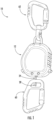
FIG. 1 is a perspective view of a lanyard, according to an embodiment. -
FIG. 2 is a side view of the lanyard ofFIG. 1 , according to an exemplary embodiment. -
FIG. 3 is a cross-section view of the lanyard ofFIG. 1 taken along line 3-3 inFIG. 2 , according to an exemplary embodiment. -
FIG. 4 is another cross-section view of the lanyard ofFIG. 1 taken along line 3-3 inFIG. 2 , in which the arm is in a different position than inFIG. 3 , according to an exemplary embodiment. -
FIG. 5 is a side view of a lanyard, according to another embodiment. -
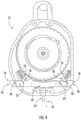
FIG. 6 is a cross-section view of the lanyard ofFIG. 5 , according to an exemplary embodiment. -
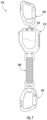
FIG. 7 is a side view of a lanyard, according to another embodiment. - Referring generally to the figures, various embodiments of a lanyard are shown. Lanyards are used as a safety measure to secure tools/equipment to an anchor point, for example, while working at height. To enhance safety, a lanyard may couple to tools, protective equipment, tool batteries, other construction devices/equipment, etc. and tether them when operating the tools at height. Various regulations (e.g., OSHA regulations) may require a lanyard when an operator uses a tool at height. When a tool is dropped at height, the lanyard couples the tool to an anchor point and prevents the tool from dropping further than a distance provided by the lanyard. This prevents a safety hazard and also protects the tool from the damage that may be otherwise caused by the fall.
- Applicant has developed an innovative locking/biasing mechanism that restricts movement of the lanyard spool. When the locking mechanism is in the locked position, the lanyard spool is biased from rotating unless a sufficient pulling force is exerted on the cord, in which case the locking mechanism disengages from the lanyard spool. This disengagement functionality permits the lanyard cord to be extended without requiring the user to directly interface with and actuate the locking mechanism. When the locking mechanism is in the unlocked position, the lanyard spool is permitted to rotate without interference from the locking mechanism. The locking mechanism includes locking components that bias the locking mechanism to remain stationary when in the locked and the unlocked positions.
- Referring to
FIGS. 1-4 , various aspects of a device, shown as lanyard 10, are shown. Lanyard 10 includes a first retractable coupling mechanism, shown as carabiner 60, and a second fixed coupling mechanism, shown as carabiner 62, coupled tohousing 12. Both carabiner 60 and carabiner 62 are coupled tohousing 12.Housing 12 includes anopening 14. An elongate flexible structure, shown ascord 24, has aninner end 26 coupled tospool 20 and an opposingouter end 28 extending out of opening 14. Carabiner 60 is coupled toouter end 28 ofcord 24.Cord 24 is extendable and retractable fromhousing 12, thereby reducing and increasing the distance that carabiner 60 may be separated fromhousing 12. Carabiner 62 is coupled tohousing 12 such that the carabiner 62 andhousing 12 remain a relatively fixed distance from each other. - In use, carabiner 60 is coupled to items such as tools, protective equipment, tool batteries, other construction devices/equipment, etc. Carabiner 62 anchors lanyard 10 to an anchor point, such as a belt, scaffold, etc. If and when the item coupled to carabiner 60 is dropped, lanyard 10 anchors the item to the anchor point to which carabiner 62 is coupled.
- Spool 20 is rotatably coupled to housing 12 (e.g., rotatably mounted within housing 12) such that
spool 20 rotates around axis 8 with respect tohousing 12. In a specific embodiment,spool 20 is a reel. An elongate structure, shown ascord 24, is wound aroundspool 20. Ascord 24 is extracted fromhousing 12 through opening 14,spool 20 rotates around axis 8 in a second rotational direction, shown as direction 48.Spool 20 rotates in a first direction, opposite direction 48, when thecord 24 to retractcord 24 withinhousing 12 and ontospool 20.Retraction system 30biases spool 20 opposite rotational direction 48, thereby biasingcord 24 towards being retracted withinhousing 12 ontospool 20. In a specificembodiment retraction system 30 includes a spring, such as a spiral spring. In a specific embodiment,retraction system 30 is coupled tospool 20 andretraction system 30biases cord 24 to be rewound ontospool 20. In a specific embodiment,arm 32 interfacing withspool 20 whenarm 32 is in the lockedposition biases spool 20 from rotating, such as rotating in the direction opposite rotational direction 48. In a specific embodiment,arm 32 is a shuttle that slides linearly with respect tohousing 12. - In another embodiment, the configuration of the lanyard is flipped and thus in the reverse arrangement. For example, as
cord 24 is extracted fromhousing 12,spool 20 rotates around axis 8 opposite rotational direction 48,tooth 38 of arm are on the right side ofarm 32, andarm 32 is in the locked position whenarm 32 is extending out the left-side of housing (from the perspective ofFIG. 3 ). -
Arm 32 actuates alonglinear axis 40 such that whenarm 32 is in the locked position (best shownFIG. 3 ), a protrusion fromarm 32, shown astooth 38, interfaces withteeth 22 ofspool 20. Whentooth 38 andteeth 22 interface,arm 32 resistsspool 20 rotating in either direction 48 or opposite direction 48. Stated another way,arm 32 interfaces withspool 20 whenarm 32 is in the locked position to bias thespool 20 from rotating. Whenarm 32 is in the unlocked position (best shownFIG. 4 ),tooth 38 ofarm 32 does not interface withteeth 22 ofspool 20, soarm 32 no longer resistsspool 20 rotating. In a specific embodiment,arm 32 is slideably coupled tohousing 12 such thatarm 32 actuates between the locked and unlocked position viaarm 32 sliding with respect tohousing 12. In a specific embodiment,arm 32 includesbody 33,first end 34 ofbody 33, and opposingsecond end 36 ofbody 33 oppositefirst end 34. - A first biasing component, shown as a spring-biased
ball 56, and a second biasing component, also shown as a spring-biasedball 58, selectively resistarm 32 actuating between the locked position (FIG. 3 ) and the unlocked position (FIG. 4 ). Whenarm 32 is in the locked position (FIG. 3 ), spring-biasedball 56 interfaces withrecess 50 and spring-biasedball 58 interfaces with recess 64, thereby biasingarm 32 to remain in the locked position. - To actuate
arm 32 from the locked position to the unlocked position, a user can exert a force onsecond end 36 ofarm 32 sufficient to overcome the biasing forces of spring-biasedball 56 and spring-biasedball 58. When sufficient force is exerted onsecond end 36 ofarm 32,arm 32 moves from the locked position (FIG. 3 ) to the unlocked position (FIG. 4 ) untilfirst end 34 ofarm 32 extends from opening 16 ofhousing 12 andsecond end 36 ofarm 32 no longer extends from opening 18 ofhousing 12. Whenarm 32 is in the unlocked position (FIG. 4 ), spring-biasedball 56 interfaces withrecess 52, and spring-biasedball 58 interfaces with recess 66, thereby biasingarm 32 to remain in the unlocked position. - In a specific embodiment, when
arm 32 is in the locked position,first end 34 ofarm 32 extends out ofhousing 12 andsecond end 36 does not extend out ofhousing 12, andarm 32 interfaces withspool 20 to biasspool 20 from rotating whenarm 32 is in the locked position. In a specific embodiment, whenarm 32 is in the unlocked position,second end 36 extends out ofhousing 12 andfirst end 34 does not extend out ofhousing 12, andarm 32 does not biasspool 20 from rotating when thearm 32 is in the unlocked position. - In a specific embodiment,
arm 32 transitions from the locked position to the unlocked position in response tocord 24 receiving a pulling force (e.g., a force indirection 70; seeFIG. 4 ) greater than a threshold amount of force (e.g., an amount of force sufficient to overcome the biasing forces of arm biasing system 54). For example, whencord 24 receives the threshold amount of force,teeth 22 ofspool 20 interface withtooth 38 to pusharm 32 to the unlocked position (e.g., to the left as seen inFIGS. 3 and4 ). - In another embodiment, when
arm 32 is in the locked position thenarm 32 extends from both ends ofhousing 12, and whenarm 32 is in the unlocked position thenarm 32 extends from both ends ofhousing 12. - Alternatively, exerting sufficient force on
cord 24 actuatesarm 32 from the locked position to the unlocked position. As a pulling force is exerted oncord 24 relative tohousing 12,cord 24 exerts a corresponding rotational force in direction 48 onspool 20. When sufficient force is exerted onspool 20,teeth 22 ofspool 20push tooth 38 ofarm 32 to the left (from the perspective ofFIG. 3 ) alonglinear axis 40. Thus, if sufficient pulling force is exerted oncord 24,arm 32 will be actuated from the locked position (FIG. 3 ). - In a specific embodiment,
arm biasing system 54 includes first arm-biasingmechanism 53 and second arm-biasingmechanism 55.Arm biasing system 54biases arm 32 to remain in the locked position andarm biasing system 54biases arm 32 to remain in the unlocked position. First arm-biasingmechanism 53 includes first spring-biasedball 56 and a first biasing element, shown asspring 72, that biases first spring-biasedball 56 againstarm 32. Second arm-biasingmechanism 55 includes second spring-biasedball 58 and a second biasing element, shown asspring 74, that biases second spring-biasedball 58 againstarm 32. - In a specific embodiment, each of first arm-biasing
mechanism 53 and second arm-biasingmechanism 55 include a detent that interfaces with one of spring-biasedball mechanism 53biases arm 32 to remain in the locked position, and second arm-biasingmechanism 55biases arm 32 to remain in the unlocked position. In a specific embodiment, first arm-biasingmechanism 53further biases arm 32 to remain in the unlocked position in addition to biasingarm 32 to remain in the locked position. In a specific embodiment, second arm-biasingmechanism 55further biases arm 32 to remain in the locked position in addition to biasingarm 32 to remain in the unlocked position. - In an alternate embodiment,
arm biasing system 54 only includes one of first arm-biasingmechanism 53 and second arm-biasing mechanism 55 (e.g., only one spring-biasedball 56 and only one spring-biased ball 58). - In a specific embodiment,
arm 32 includes a hard-stop, shown aslower protrusion 42, that restricts the range of sliding motion byarm 32.Lower protrusion 42 ofarm 32 interfaces withleft wall 44 and right wall 46 ofhousing 12, to restrictarm 32 to positions between the locked position (FIG. 3 ) and the unlocked position (FIG. 4 ). In anotherembodiment arm 32 does not includelower protrusions 42 that interfaces leftwall 44 and right wall 46 ofhousing 12. - Referring to
FIG. 5 andFIG. 6 , alanyard 110 is shown according to an exemplary embodiment.Lanyard 110 is similar to lanyard 10 with the exception of the differences described. -
Lanyard 110 includes a first locking component, shown as a spring-biasedball 156, and a second locking component, shown as a spring-biasedball 158. Spring-biasedballs arm 132 alongaxis 140.Arm 132 actuates alongaxis 140 with respect tohousing 112 between a locked position (FIG. 5 ) and an unlocked position, and spring-biasedballs retain arm 132 in the locked or unlocked position following selection of the position by the user. - When
arm 132 is in the locked position (FIG. 5 ), spring-biasedball 156 interfaces withrecess 150 and spring-biasedball 158 interfaces withrecess 164. and In this position, the engagement of spring-biasedballs recesses arm 132 in the locked position. Whenarm 132 is in the unlocked position, spring-biasedball 156 interfaces withrecess 152 and spring-biasedball 158 interfaces withrecess 166. In this position, the engagement of spring-biasedballs recesses arm 132 in the unlocked position. - To actuate
arm 132 from the locked position to the unlocked position, a user can exert a force onsecond end 136 ofarm 132 sufficient to overcome the biasing forces of spring-biasedball 156 and of spring-biasedball 158. When sufficient force is exerted onsecond end 136 ofarm 32,arm 132 moves from the locked position (FIG. 5 ) to the unlocked position untilfirst end 134 ofarm 132 extends fromhousing 112 andsecond end 136 ofarm 132 no longer extends fromhousing 112. - Alternatively, exerting sufficient force on
cord 124 actuatesarm 132 from the locked position to the unlocked position. As a pulling force is exerted oncord 124 relative tohousing 112,cord 124 exerts a corresponding rotational force onspool 120. When sufficient force is exerted onspool 120,teeth 122 ofspool 120push tooth 138 ofarm 132 to the left (from the perspective ofFIG. 6 ) alonglinear axis 140. Thus, if sufficient pulling force is exerted oncord 124,arm 132 will be actuated from the locked position (FIG. 6 ). - Referring to
FIG. 7 , alanyard 210 is shown according to an exemplary embodiment.Lanyard 210 is similar to lanyard 10 orlanyard 110 with the exception of the differences described. -
Lanyard 210 includes fixedcoupling unit 262 coupled tohousing 212 viaflexible coupler 280. In a specific embodiment,flexible coupler 280 is formed from a fabric material. Applicant has observed thatflexible coupler 280, such as whenflexible coupler 280 is formed from a fabric material, absorbs some of the shock load during drop events (e.g., when the object coupled toretractable coupling unit 260 is dropped), thereby reducing the load on the components withinlanyard 210 and correspondingly reducing the likelihood of components withinlanyard 210 being broken and/or damaged. - It should be understood that the figures illustrate the exemplary embodiments in detail, and it should be understood that the present application is not limited to the details or methodology set forth in the description or illustrated in the figures. It should also be understood that the terminology is for description purposes only and should not be regarded as limiting.
- Further modifications and alternative embodiments of various aspects of the disclosure will be apparent to those skilled in the art in view of this description. Accordingly, this description is to be construed as illustrative only. The construction and arrangements, shown in the various exemplary embodiments, are illustrative only. Although only a few embodiments have been described in detail in this disclosure, many modifications are possible (e.g., variations in sizes, dimensions, structures, shapes and proportions of the various elements, values of parameters, mounting arrangements, use of materials, colors, orientations, etc.) without materially departing from the novel teachings and advantages of the subject matter described herein. Some elements shown as integrally formed may be constructed of multiple parts or elements, the position of elements may be reversed or otherwise varied, and the nature or number of discrete elements or positions may be altered or varied. The order or sequence of any process, logical algorithm, or method steps may be varied or re-sequenced according to alternative embodiments. Other substitutions, modifications, changes and omissions may also be made in the design, operating conditions and arrangement of the various exemplary embodiments without departing from the scope of the invention, as defined by the appended claims.
- Unless otherwise expressly stated, it is in no way intended that any method set forth herein be construed as requiring that its steps be performed in a specific order. Accordingly, where a method claim does not actually recite an order to be followed by its steps or it is not otherwise specifically stated in the claims or descriptions that the steps are to be limited to a specific order, it is in no way intended that any particular order be inferred. In addition, as used herein, the article "a" is intended to include one or more component or element, and is not intended to be construed as meaning only one. As used herein, "rigidly coupled" refers to two components being coupled in a manner such that the components move together in a fixed positional relationship when acted upon by a force.
Claims (17)
- A lanyard (10, 110, 210) comprising:a housing (12, 112) comprising an opening (14);a reel (20, 120) rotatably mounted within the housing (12, 112);an elongate structure (24, 124) wound around the reel (20, 120), the elongate structure (24, 124) having an inner end coupled to the reel (20, 120) and an opposing outer end (28) extending out of the opening (14);a first coupling mechanism coupled (60) to the outer end (28) of the elongate structure (24, 124);a second coupling mechanism (62) coupled to the housing (12, 112);a retraction system (30) coupled to the reel (20, 120), wherein the retraction system (30) biases the elongate structure (24, 124) to be rewound onto the reel (20, 120); andcharacterized by:
an arm (32, 132) coupled to the housing (12, 112), the arm (32, 132) comprising a body (33), a first end (36, 136) of the body (33), and an opposing second end (34, 134) of the body (33), wherein the arm (32, 132) actuates between:a locked position in which the first end (36, 136) extends out of the housing (12, 112) and the second end (34, 134) does not extend out of the housing (12, 112), the arm (32, 132) interfacing with the reel (20, 120) to bias the reel (20, 120) from rotating when the arm (32, 132) is in the locked position; andan unlocked position in which the second end (34, 134) extends out of the housing (12, 112) and the first end (36, 136) does not extend out of the housing (12, 112), wherein the arm (32, 132) does not bias the reel (20, 120) from rotating when the arm (32, 312) is in the unlocked position. - The lanyard (10, 110, 210) of claim 1, wherein the arm (32, 132) transitions from the locked position to the unlocked position in response to the elongate structure (24, 124) receiving a pulling force greater than a threshold amount of force.
- The lanyard (10, 110, 210) of claim 1, further comprising:a first arm biasing mechanism (54, 50, 64) that biases the arm to remain in the locked position; anda second arm biasing mechanism (54, 52, 66) that biases the arm to remain in the unlocked position.
- The lanyard (10, 110, 210) of claim 3, the first arm biasing mechanism (54, 50 64) comprises a first ball (56) and a first spring (72) that biases the first ball (56) against the arm (32, 132), and the second arm biasing mechanism (54, 52, 66) comprises a second ball (58) and a second spring (74) that biases the second ball (58) against the arm (32, 132).
- The lanyard (210) of claim 1, further comprising a flexible coupler (280) that couples the second coupling mechanism (62) to the housing (12, 112).
- The lanyard (210) of claim 5, wherein the flexible coupler (280) is formed from a fabric material.
- The lanyard (10, 110, 210) of claim 1, wherein the retraction system (30) comprises a spring.
- The lanyard (10, 110, 210) of claim 1, wherein the arm (32, 132) actuates between the locked position and the unlocked position via the arm (32, 132) sliding with respect to the housing.
- The lanyard (10, 110, 210) of claim 1, further comprising:
an arm biasing system (54, 154) that biases the arm (32, 132) to remain in the locked position and that biases the arm (32, 132) to remain in the unlocked position. - The lanyard (10, 110, 210) of claim 9, wherein the arm biasing system (54, 154) comprises:a first arm biasing mechanism (53) that biases the arm (32, 132) to remain in the locked position; anda second arm biasing mechanism (55) that biases the arm (32, 132) to remain in the unlocked position.
- The lanyard (10, 110, 210) of claim 10, wherein the first arm biasing mechanism (53) further biases the arm (32, 132) to remain in the unlocked position.
- The lanyard (10, 110, 210) of claim 11, wherein the second arm biasing mechanism (55) further biases the arm (32, 132) to remain in the locked position.
- The lanyard (10, 110, 210) of claim 9, wherein the arm (32, 132) actuates between the locked position and the unlocked position via the arm (32, 132) sliding with respect to the housing (12, 112).
- The lanyard (10, 110, 210) of claim 1, wherein the reel (20, 120) rotates in a first direction to retract the elongate structure (24, 124) into the housing (12, 112), and the reel (20, 120) rotates in an opposing second direction when the elongate structure (24, 124) is being pulled from the housing (12, 112), wherein the lanyard (10, 110, 210) further comprises:
an arm lock mechanism (54) that biases the arm (32, 132) to remain in the locked position, wherein the arm (32, 132) transitions from the locked position to the unlocked position in response to the elongate structure (24, 124) receiving a pulling force greater than a threshold amount of force. - The lanyard (10, 110, 210) of claim 14, further comprising an arm biasing system (54, 154) that biases the arm (32, 132) to remain in the locked position and that biases the arm (32, 132) to remain in the unlocked position.
- The lanyard (10, 110, 210) of claim 15, wherein the arm biasing system (54, 154) comprises:a first arm biasing mechanism (53) that biases the arm (32, 132) to remain in the locked position; anda second arm biasing mechanism (55) that biases the arm (32, 132) to remain in the unlocked position.
- The lanyard (10, 110, 210) of claim 14, wherein the arm (32, 132) actuates between the locked position and the unlocked position via the arm (32, 132) sliding with respect to the housing (12, 112).
Applications Claiming Priority (3)
| Application Number | Priority Date | Filing Date | Title |
|---|---|---|---|
| US202063053068P | 2020-07-17 | 2020-07-17 | |
| US202063092057P | 2020-10-15 | 2020-10-15 | |
| PCT/US2021/041929 WO2022016033A1 (en) | 2020-07-17 | 2021-07-16 | Lanyard with locking arm |
Publications (3)
| Publication Number | Publication Date |
|---|---|
| EP4182252A1 EP4182252A1 (en) | 2023-05-24 |
| EP4182252A4 EP4182252A4 (en) | 2024-08-07 |
| EP4182252B1 true EP4182252B1 (en) | 2025-07-02 |
Family
ID=79554320
Family Applications (1)
| Application Number | Title | Priority Date | Filing Date |
|---|---|---|---|
| EP21843324.1A Active EP4182252B1 (en) | 2020-07-17 | 2021-07-16 | Lanyard with locking arm |
Country Status (4)
| Country | Link |
|---|---|
| US (1) | US11945682B2 (en) |
| EP (1) | EP4182252B1 (en) |
| CN (1) | CN115715269A (en) |
| WO (1) | WO2022016033A1 (en) |
Families Citing this family (4)
| Publication number | Priority date | Publication date | Assignee | Title |
|---|---|---|---|---|
| USD979379S1 (en) * | 2022-11-08 | 2023-02-28 | Shenzhen Banmiao Technology Co., Ltd. | Locking retractor |
| US20240252855A1 (en) * | 2023-01-26 | 2024-08-01 | Honeywell Safety Products Usa, Inc. | Retractable lifeline apparatus and method of using the same |
| US20240290227A1 (en) * | 2023-02-24 | 2024-08-29 | Lisa LeBoeuf | Security Badge Device |
| USD1013366S1 (en) * | 2023-11-10 | 2024-02-06 | Shenzhen Banmiao Technology Co., Ltd. | Locking retractor |
Family Cites Families (49)
| Publication number | Priority date | Publication date | Assignee | Title |
|---|---|---|---|---|
| US3165059A (en) | 1962-05-08 | 1965-01-12 | Allan M Saunders | Lanyard operated, delay arming mechanism |
| AT294796B (en) | 1968-07-30 | 1971-12-10 | Sandoz Ag | Process for the production of peroxycarboxylic acids |
| GB2132172A (en) | 1982-11-04 | 1984-07-04 | Tajima Industry Co Ltd | Hanging device cable reel |
| GB8500790D0 (en) | 1985-01-12 | 1985-02-13 | Parkinson S | Extensible suspension device |
| US5423494A (en) * | 1992-01-10 | 1995-06-13 | Daido Tokushuko Kabushiki Kaisha | Pet rope winder |
| US5245761A (en) * | 1992-02-25 | 1993-09-21 | Arthur Waldherr | Locking mechanism for retractable tape |
| JPH074795U (en) * | 1993-06-15 | 1995-01-24 | 株式会社キッツ | Flip-up gate |
| US5513785A (en) * | 1994-03-21 | 1996-05-07 | Campagna, Jr.; Gerald P. | Gun retention system |
| US5471761A (en) * | 1994-11-07 | 1995-12-05 | Cheng; H. T. | Power-driven tape measure |
| CN2241646Y (en) * | 1995-12-08 | 1996-12-04 | 山东省聊城运输机械厂 | Mechanical variable-speed locking mechanism for motor vehicle |
| GB2331508B (en) | 1997-02-28 | 1999-08-04 | John Quentin Phillipps | Lead storage device |
| DE29903185U1 (en) | 1999-02-22 | 1999-05-12 | Techno Finish GmbH, 99846 Seebach | Switch mechanism for pulling in cables on cable drums |
| DE19930092A1 (en) * | 1999-06-30 | 2001-01-11 | Hoechstmass Balzer Gmbh & Co | Extending belt or dog lead has locking mechanism comprising catch with spring which biases it towards e centre of housing containing the belt and which cooperates with teeth around perimeter of belt reel |
| US7857099B2 (en) | 2001-04-24 | 2010-12-28 | Reliance Industries, Llc | Twin retractable for fall arrest |
| US6536697B2 (en) | 2001-07-10 | 2003-03-25 | Chin-Yuan Tsan | Structure of automatic suspender reeling device |
| US8794560B2 (en) * | 2001-08-10 | 2014-08-05 | Hammerhead Industries, Inc. | Retracting tether for cell phones, pagers, and PDAs |
| DE10164413A1 (en) * | 2001-12-28 | 2003-07-17 | Thomas Kreuziger | Safety unit for a vehicle tow cable is in two parts, which separate on a dangerous condition and can be fitted together again to restore the link without damage to the cable |
| US7295984B2 (en) | 2002-05-09 | 2007-11-13 | Qwest Communications International Inc. | Systems and methods for providing voice and data interfaces to web services-based applications |
| US20050045676A1 (en) | 2003-08-29 | 2005-03-03 | BASS Robert | Portable carrying device with retractable strap |
| US20060283081A1 (en) | 2004-10-22 | 2006-12-21 | Robert Killen | Adjustable hanger for a potted plant |
| US7395984B2 (en) * | 2005-01-27 | 2008-07-08 | Woodhead Industries, Inc. | Safety tether for hand tools |
| GB0600269D0 (en) | 2006-01-07 | 2006-02-15 | Bekaert Handling Ltd | Retractable cord holder |
| GB2437074B (en) | 2006-04-11 | 2008-05-28 | Maxess Ltd | Safety line apparatus |
| US7374123B2 (en) * | 2006-09-05 | 2008-05-20 | Louis A. Kish | Rewind mechanism |
| DE102006057901B3 (en) | 2006-12-08 | 2008-06-19 | Carl Stahl Kromer Gmbh | Device for balancing the weight of a suspended load |
| CN200999000Y (en) * | 2007-01-11 | 2008-01-02 | 浙江信阳实业有限公司 | Vehicle shift self-locking mechanism |
| US20090084697A1 (en) | 2007-09-27 | 2009-04-02 | Gross Travis A | Retractable carrying device for an optical device |
| US20100206922A1 (en) | 2007-09-27 | 2010-08-19 | Gross Travis A | Retractable carrying device for an optical device |
| US20090242595A1 (en) | 2007-09-27 | 2009-10-01 | Gross Travis A | Retractable carrying device for an optical device |
| US8102630B2 (en) | 2008-07-22 | 2012-01-24 | Sahul Hameed Abdul Kader Jailani | Method for maintaining connectivity in failed switches of stack |
| US20100116922A1 (en) * | 2008-11-13 | 2010-05-13 | Reliance Industries, Llc | Cable reel lock for fall arrestor |
| AU2010205907B2 (en) | 2009-01-19 | 2013-11-14 | Roofsafe-T-Systems Pty Limited | Self-retracting lifeline |
| US8746519B2 (en) | 2010-01-15 | 2014-06-10 | West Coast Chain Mfg. Co. | Releasable attachment apparatus |
| DE102011009831A1 (en) * | 2011-01-31 | 2012-08-02 | Schaeffler Technologies Gmbh & Co. Kg | Device for locking e.g. switching shaft of automatic or automated gear box of motor car, has locking element connected with switching element for locking or releasing element and releasably fixed with interposition of ball by plunger |
| WO2013003402A2 (en) | 2011-06-29 | 2013-01-03 | Key Safety Systems, Inc. | Fall arrester |
| CN103115142A (en) * | 2011-11-17 | 2013-05-22 | 常州联发凯迪机械有限公司 | Out-of-gear prevention mechanism for tractor |
| DE102012206343B4 (en) | 2012-04-18 | 2015-08-27 | Siemens Aktiengesellschaft | Force equalization device and use in a medical device |
| US20130276718A1 (en) * | 2012-04-19 | 2013-10-24 | Rollo Pet Company, Llc | Apparatus for retraction and extension of a leash or other flexible material |
| KR101441049B1 (en) * | 2013-01-09 | 2014-09-17 | 스왈록아시아 주식회사 | Fall for self-suppression, self-escape towing cable device |
| US20150157116A1 (en) | 2013-12-05 | 2015-06-11 | Brent Williams | Retractable Electronics Protection |
| CN203944051U (en) * | 2014-06-24 | 2014-11-19 | 北京成昊硕电气科技有限公司 | A kind of telescopic anti-fall Lanyard device and full body harness thereof |
| GB2548879B (en) | 2016-03-31 | 2018-09-05 | Zwart Klaas | An abseiling device |
| CN107269203B (en) * | 2016-04-06 | 2019-05-17 | 亿丰综合工业股份有限公司 | Curtain control mechanism and curtain system thereof |
| CN105822742B (en) * | 2016-04-28 | 2018-01-05 | 中国科学院长春光学精密机械与物理研究所 | The spacing and automatic unlocking mechanism of rotary axis |
| WO2018140356A1 (en) | 2017-01-27 | 2018-08-02 | Fiskars Brands, Inc. | Equipment tether |
| CN207856105U (en) | 2017-08-25 | 2018-09-14 | 吴哲雄 | Agricultural safety anti-fall device |
| CN109833571B (en) * | 2017-11-29 | 2024-05-24 | 国网山东省电力公司宁阳县供电公司 | A buckle-type pull-out dual-control safety belt system |
| CN209383203U (en) * | 2018-11-16 | 2019-09-13 | 青岛海诺铸业有限公司 | A kind of cable chain draw off gear |
| DE202018107429U1 (en) * | 2018-12-27 | 2019-02-12 | Newkey Technology Development Limited | Retractable leash with automatic locking and unlocking function |
-
2021
- 2021-07-16 WO PCT/US2021/041929 patent/WO2022016033A1/en not_active Ceased
- 2021-07-16 EP EP21843324.1A patent/EP4182252B1/en active Active
- 2021-07-16 US US17/378,018 patent/US11945682B2/en active Active
- 2021-07-16 CN CN202180040965.1A patent/CN115715269A/en active Pending
Also Published As
| Publication number | Publication date |
|---|---|
| EP4182252A1 (en) | 2023-05-24 |
| US11945682B2 (en) | 2024-04-02 |
| CN115715269A (en) | 2023-02-24 |
| WO2022016033A1 (en) | 2022-01-20 |
| EP4182252A4 (en) | 2024-08-07 |
| US20220017325A1 (en) | 2022-01-20 |
Similar Documents
| Publication | Publication Date | Title |
|---|---|---|
| US11945682B2 (en) | Lanyard with locking arm | |
| US7395984B2 (en) | Safety tether for hand tools | |
| US8683710B2 (en) | Tape measure tool with lanyard | |
| US20130008933A1 (en) | Tool belt with integrated tool retraction mechanism | |
| EP1993674B1 (en) | Self-retracting lanyard and braking mechanism with pawl lockout | |
| CA3050261C (en) | Equipment tether | |
| US20190209877A1 (en) | Retractable lifeline assembly | |
| WO2011046732A1 (en) | Self-retracting lifeline with reserve lifeline portion | |
| GB2451835A (en) | Fall arrest block | |
| EP3307058B1 (en) | Retractable animal leash and method of operating it | |
| US20110265332A1 (en) | Foldable tethered hand tool | |
| TWI564053B (en) | Lanyard and seat belt with the lanyard | |
| EP3280970A1 (en) | Hand tool with retractable tether | |
| JP2006037712A (en) | Fall preventing device of worker | |
| US12108867B2 (en) | Tool lanyard device and method of use thereof | |
| CN110038234B (en) | Rope winding knapsack of protection system | |
| TWI625293B (en) | Tool cord storage device | |
| US11993477B2 (en) | Retractable tool lanyard | |
| JP2532071Y2 (en) | Safety equipment for fall prevention | |
| JP2021090540A (en) | Safety belt, fall prevention equipment and fall prevention method using the same safety belt | |
| WO2007080360A1 (en) | Retractable cord holder | |
| CN210121299U (en) | Movable self-locking safety protection system | |
| JP2002179342A (en) | Tool fall prevention tool | |
| GB2399564A (en) | Safety system for retaining tools | |
| WO2014009746A1 (en) | A tool safety device |
Legal Events
| Date | Code | Title | Description |
|---|---|---|---|
| STAA | Information on the status of an ep patent application or granted ep patent |
Free format text: STATUS: THE INTERNATIONAL PUBLICATION HAS BEEN MADE |
|
| PUAI | Public reference made under article 153(3) epc to a published international application that has entered the european phase |
Free format text: ORIGINAL CODE: 0009012 |
|
| STAA | Information on the status of an ep patent application or granted ep patent |
Free format text: STATUS: REQUEST FOR EXAMINATION WAS MADE |
|
| 17P | Request for examination filed |
Effective date: 20221228 |
|
| AK | Designated contracting states |
Kind code of ref document: A1 Designated state(s): AL AT BE BG CH CY CZ DE DK EE ES FI FR GB GR HR HU IE IS IT LI LT LU LV MC MK MT NL NO PL PT RO RS SE SI SK SM TR |
|
| DAV | Request for validation of the european patent (deleted) | ||
| DAX | Request for extension of the european patent (deleted) | ||
| A4 | Supplementary search report drawn up and despatched |
Effective date: 20240709 |
|
| RIC1 | Information provided on ipc code assigned before grant |
Ipc: A62B 35/00 20060101ALI20240703BHEP Ipc: A45F 5/00 20060101ALI20240703BHEP Ipc: B65H 75/44 20060101AFI20240703BHEP |
|
| GRAP | Despatch of communication of intention to grant a patent |
Free format text: ORIGINAL CODE: EPIDOSNIGR1 |
|
| STAA | Information on the status of an ep patent application or granted ep patent |
Free format text: STATUS: GRANT OF PATENT IS INTENDED |
|
| RIC1 | Information provided on ipc code assigned before grant |
Ipc: A62B 35/00 20060101ALI20250128BHEP Ipc: A45F 5/00 20060101ALI20250128BHEP Ipc: B65H 75/44 20060101AFI20250128BHEP |
|
| INTG | Intention to grant announced |
Effective date: 20250207 |
|
| GRAS | Grant fee paid |
Free format text: ORIGINAL CODE: EPIDOSNIGR3 |
|
| GRAA | (expected) grant |
Free format text: ORIGINAL CODE: 0009210 |
|
| STAA | Information on the status of an ep patent application or granted ep patent |
Free format text: STATUS: THE PATENT HAS BEEN GRANTED |
|
| AK | Designated contracting states |
Kind code of ref document: B1 Designated state(s): AL AT BE BG CH CY CZ DE DK EE ES FI FR GB GR HR HU IE IS IT LI LT LU LV MC MK MT NL NO PL PT RO RS SE SI SK SM TR |
|
| REG | Reference to a national code |
Ref country code: GB Ref legal event code: FG4D |
|
| REG | Reference to a national code |
Ref country code: CH Ref legal event code: EP |
|
| REG | Reference to a national code |
Ref country code: DE Ref legal event code: R096 Ref document number: 602021033528 Country of ref document: DE |
|
| REG | Reference to a national code |
Ref country code: IE Ref legal event code: FG4D |
|
| PGFP | Annual fee paid to national office [announced via postgrant information from national office to epo] |
Ref country code: DE Payment date: 20250729 Year of fee payment: 5 |
|
| PGFP | Annual fee paid to national office [announced via postgrant information from national office to epo] |
Ref country code: AT Payment date: 20251020 Year of fee payment: 5 |
|
| P01 | Opt-out of the competence of the unified patent court (upc) registered |
Free format text: CASE NUMBER: UPC_APP_7282_4182252/2025 Effective date: 20250916 |
|
| REG | Reference to a national code |
Ref country code: NL Ref legal event code: MP Effective date: 20250702 |
|
| PG25 | Lapsed in a contracting state [announced via postgrant information from national office to epo] |
Ref country code: PT Free format text: LAPSE BECAUSE OF FAILURE TO SUBMIT A TRANSLATION OF THE DESCRIPTION OR TO PAY THE FEE WITHIN THE PRESCRIBED TIME-LIMIT Effective date: 20251103 |
|
| PG25 | Lapsed in a contracting state [announced via postgrant information from national office to epo] |
Ref country code: NL Free format text: LAPSE BECAUSE OF FAILURE TO SUBMIT A TRANSLATION OF THE DESCRIPTION OR TO PAY THE FEE WITHIN THE PRESCRIBED TIME-LIMIT Effective date: 20250702 |
|
| REG | Reference to a national code |
Ref country code: AT Ref legal event code: MK05 Ref document number: 1809069 Country of ref document: AT Kind code of ref document: T Effective date: 20250702 |
|
| PG25 | Lapsed in a contracting state [announced via postgrant information from national office to epo] |
Ref country code: IS Free format text: LAPSE BECAUSE OF FAILURE TO SUBMIT A TRANSLATION OF THE DESCRIPTION OR TO PAY THE FEE WITHIN THE PRESCRIBED TIME-LIMIT Effective date: 20251102 |
|
| PG25 | Lapsed in a contracting state [announced via postgrant information from national office to epo] |
Ref country code: NO Free format text: LAPSE BECAUSE OF FAILURE TO SUBMIT A TRANSLATION OF THE DESCRIPTION OR TO PAY THE FEE WITHIN THE PRESCRIBED TIME-LIMIT Effective date: 20251002 |
|
| REG | Reference to a national code |
Ref country code: LT Ref legal event code: MG9D |
|
| PG25 | Lapsed in a contracting state [announced via postgrant information from national office to epo] |
Ref country code: AT Free format text: LAPSE BECAUSE OF FAILURE TO SUBMIT A TRANSLATION OF THE DESCRIPTION OR TO PAY THE FEE WITHIN THE PRESCRIBED TIME-LIMIT Effective date: 20250702 |
|
| PG25 | Lapsed in a contracting state [announced via postgrant information from national office to epo] |
Ref country code: FI Free format text: LAPSE BECAUSE OF FAILURE TO SUBMIT A TRANSLATION OF THE DESCRIPTION OR TO PAY THE FEE WITHIN THE PRESCRIBED TIME-LIMIT Effective date: 20250702 |
|
| PG25 | Lapsed in a contracting state [announced via postgrant information from national office to epo] |
Ref country code: HR Free format text: LAPSE BECAUSE OF FAILURE TO SUBMIT A TRANSLATION OF THE DESCRIPTION OR TO PAY THE FEE WITHIN THE PRESCRIBED TIME-LIMIT Effective date: 20250702 |
|
| PG25 | Lapsed in a contracting state [announced via postgrant information from national office to epo] |
Ref country code: GR Free format text: LAPSE BECAUSE OF FAILURE TO SUBMIT A TRANSLATION OF THE DESCRIPTION OR TO PAY THE FEE WITHIN THE PRESCRIBED TIME-LIMIT Effective date: 20251003 |
|
| PG25 | Lapsed in a contracting state [announced via postgrant information from national office to epo] |
Ref country code: CZ Free format text: LAPSE BECAUSE OF FAILURE TO SUBMIT A TRANSLATION OF THE DESCRIPTION OR TO PAY THE FEE WITHIN THE PRESCRIBED TIME-LIMIT Effective date: 20250702 Ref country code: SE Free format text: LAPSE BECAUSE OF FAILURE TO SUBMIT A TRANSLATION OF THE DESCRIPTION OR TO PAY THE FEE WITHIN THE PRESCRIBED TIME-LIMIT Effective date: 20250702 |
|
| PG25 | Lapsed in a contracting state [announced via postgrant information from national office to epo] |
Ref country code: LV Free format text: LAPSE BECAUSE OF FAILURE TO SUBMIT A TRANSLATION OF THE DESCRIPTION OR TO PAY THE FEE WITHIN THE PRESCRIBED TIME-LIMIT Effective date: 20250702 |
|
| PG25 | Lapsed in a contracting state [announced via postgrant information from national office to epo] |
Ref country code: BG Free format text: LAPSE BECAUSE OF FAILURE TO SUBMIT A TRANSLATION OF THE DESCRIPTION OR TO PAY THE FEE WITHIN THE PRESCRIBED TIME-LIMIT Effective date: 20250702 Ref country code: PL Free format text: LAPSE BECAUSE OF FAILURE TO SUBMIT A TRANSLATION OF THE DESCRIPTION OR TO PAY THE FEE WITHIN THE PRESCRIBED TIME-LIMIT Effective date: 20250702 |
|
| PG25 | Lapsed in a contracting state [announced via postgrant information from national office to epo] |
Ref country code: RS Free format text: LAPSE BECAUSE OF FAILURE TO SUBMIT A TRANSLATION OF THE DESCRIPTION OR TO PAY THE FEE WITHIN THE PRESCRIBED TIME-LIMIT Effective date: 20251002 |
|
| PG25 | Lapsed in a contracting state [announced via postgrant information from national office to epo] |
Ref country code: ES Free format text: LAPSE BECAUSE OF FAILURE TO SUBMIT A TRANSLATION OF THE DESCRIPTION OR TO PAY THE FEE WITHIN THE PRESCRIBED TIME-LIMIT Effective date: 20250702 |
|
| REG | Reference to a national code |
Ref country code: CH Ref legal event code: H13 Free format text: ST27 STATUS EVENT CODE: U-0-0-H10-H13 (AS PROVIDED BY THE NATIONAL OFFICE) Effective date: 20260224 |
|
| PG25 | Lapsed in a contracting state [announced via postgrant information from national office to epo] |
Ref country code: LU Free format text: LAPSE BECAUSE OF NON-PAYMENT OF DUE FEES Effective date: 20250716 Ref country code: RO Free format text: LAPSE BECAUSE OF FAILURE TO SUBMIT A TRANSLATION OF THE DESCRIPTION OR TO PAY THE FEE WITHIN THE PRESCRIBED TIME-LIMIT Effective date: 20250702 |
|
| REG | Reference to a national code |
Ref country code: BE Ref legal event code: MM Effective date: 20250731 |
|
| PG25 | Lapsed in a contracting state [announced via postgrant information from national office to epo] |
Ref country code: SM Free format text: LAPSE BECAUSE OF FAILURE TO SUBMIT A TRANSLATION OF THE DESCRIPTION OR TO PAY THE FEE WITHIN THE PRESCRIBED TIME-LIMIT Effective date: 20250702 |
|
| REG | Reference to a national code |
Ref country code: DE Ref legal event code: R097 Ref document number: 602021033528 Country of ref document: DE |
|
| PG25 | Lapsed in a contracting state [announced via postgrant information from national office to epo] |
Ref country code: DK Free format text: LAPSE BECAUSE OF FAILURE TO SUBMIT A TRANSLATION OF THE DESCRIPTION OR TO PAY THE FEE WITHIN THE PRESCRIBED TIME-LIMIT Effective date: 20250702 |
|
| PG25 | Lapsed in a contracting state [announced via postgrant information from national office to epo] |
Ref country code: IT Free format text: LAPSE BECAUSE OF FAILURE TO SUBMIT A TRANSLATION OF THE DESCRIPTION OR TO PAY THE FEE WITHIN THE PRESCRIBED TIME-LIMIT Effective date: 20250702 Ref country code: BE Free format text: LAPSE BECAUSE OF NON-PAYMENT OF DUE FEES Effective date: 20250731 |
|
| PG25 | Lapsed in a contracting state [announced via postgrant information from national office to epo] |
Ref country code: CH Free format text: LAPSE BECAUSE OF NON-PAYMENT OF DUE FEES Effective date: 20250731 |
|
| PG25 | Lapsed in a contracting state [announced via postgrant information from national office to epo] |
Ref country code: SK Free format text: LAPSE BECAUSE OF FAILURE TO SUBMIT A TRANSLATION OF THE DESCRIPTION OR TO PAY THE FEE WITHIN THE PRESCRIBED TIME-LIMIT Effective date: 20250702 Ref country code: EE Free format text: LAPSE BECAUSE OF FAILURE TO SUBMIT A TRANSLATION OF THE DESCRIPTION OR TO PAY THE FEE WITHIN THE PRESCRIBED TIME-LIMIT Effective date: 20250702 |
|
| PLBE | No opposition filed within time limit |
Free format text: ORIGINAL CODE: 0009261 |
|
| STAA | Information on the status of an ep patent application or granted ep patent |
Free format text: STATUS: NO OPPOSITION FILED WITHIN TIME LIMIT |
|
| REG | Reference to a national code |
Ref country code: CH Ref legal event code: L10 Free format text: ST27 STATUS EVENT CODE: U-0-0-L10-L00 (AS PROVIDED BY THE NATIONAL OFFICE) Effective date: 20260518 |
|
| 26N | No opposition filed |
Effective date: 20260407 |
|
| PG25 | Lapsed in a contracting state [announced via postgrant information from national office to epo] |
Ref country code: MC Free format text: LAPSE BECAUSE OF FAILURE TO SUBMIT A TRANSLATION OF THE DESCRIPTION OR TO PAY THE FEE WITHIN THE PRESCRIBED TIME-LIMIT Effective date: 20250702 Ref country code: LT Free format text: LAPSE BECAUSE OF FAILURE TO SUBMIT A TRANSLATION OF THE DESCRIPTION OR TO PAY THE FEE WITHIN THE PRESCRIBED TIME-LIMIT Effective date: 20250702 |
|
| PGFP | Annual fee paid to national office [announced via postgrant information from national office to epo] |
Ref country code: GB Payment date: 20260618 Year of fee payment: 6 |
|
| PG25 | Lapsed in a contracting state [announced via postgrant information from national office to epo] |
Ref country code: IE Free format text: LAPSE BECAUSE OF NON-PAYMENT OF DUE FEES Effective date: 20250716 |
|
| PG25 | Lapsed in a contracting state [announced via postgrant information from national office to epo] |
Ref country code: FR Free format text: LAPSE BECAUSE OF NON-PAYMENT OF DUE FEES Effective date: 20250902 |
|
| PG25 | Lapsed in a contracting state [announced via postgrant information from national office to epo] |
Ref country code: CY Free format text: LAPSE BECAUSE OF FAILURE TO SUBMIT A TRANSLATION OF THE DESCRIPTION OR TO PAY THE FEE WITHIN THE PRESCRIBED TIME-LIMIT Effective date: 20250702 |