EP4182152B1 - Verbinden zweier objekte - Google Patents
Verbinden zweier objekte Download PDFInfo
- Publication number
- EP4182152B1 EP4182152B1 EP21745792.8A EP21745792A EP4182152B1 EP 4182152 B1 EP4182152 B1 EP 4182152B1 EP 21745792 A EP21745792 A EP 21745792A EP 4182152 B1 EP4182152 B1 EP 4182152B1
- Authority
- EP
- European Patent Office
- Prior art keywords
- joining element
- distal
- proximal
- tool
- joining
- Prior art date
- Legal status (The legal status is an assumption and is not a legal conclusion. Google has not performed a legal analysis and makes no representation as to the accuracy of the status listed.)
- Active
Links
Images


Classifications
-
- F—MECHANICAL ENGINEERING; LIGHTING; HEATING; WEAPONS; BLASTING
- F16—ENGINEERING ELEMENTS AND UNITS; GENERAL MEASURES FOR PRODUCING AND MAINTAINING EFFECTIVE FUNCTIONING OF MACHINES OR INSTALLATIONS; THERMAL INSULATION IN GENERAL
- F16B—DEVICES FOR FASTENING OR SECURING CONSTRUCTIONAL ELEMENTS OR MACHINE PARTS TOGETHER, e.g. NAILS, BOLTS, CIRCLIPS, CLAMPS, CLIPS OR WEDGES; JOINTS OR JOINTING
- F16B11/00—Connecting constructional elements or machine parts by sticking or pressing them together, e.g. cold pressure welding
- F16B11/002—Connecting constructional elements or machine parts by sticking or pressing them together, e.g. cold pressure welding by pressing the elements together so as to obtain plastic deformation
-
- B—PERFORMING OPERATIONS; TRANSPORTING
- B29—WORKING OF PLASTICS; WORKING OF SUBSTANCES IN A PLASTIC STATE IN GENERAL
- B29C—SHAPING OR JOINING OF PLASTICS; SHAPING OF MATERIAL IN A PLASTIC STATE, NOT OTHERWISE PROVIDED FOR; AFTER-TREATMENT OF THE SHAPED PRODUCTS, e.g. REPAIRING
- B29C65/00—Joining or sealing of preformed parts, e.g. welding of plastics materials; Apparatus therefor
- B29C65/02—Joining or sealing of preformed parts, e.g. welding of plastics materials; Apparatus therefor by heating, with or without pressure
- B29C65/08—Joining or sealing of preformed parts, e.g. welding of plastics materials; Apparatus therefor by heating, with or without pressure using ultrasonic vibrations
-
- B—PERFORMING OPERATIONS; TRANSPORTING
- B29—WORKING OF PLASTICS; WORKING OF SUBSTANCES IN A PLASTIC STATE IN GENERAL
- B29C—SHAPING OR JOINING OF PLASTICS; SHAPING OF MATERIAL IN A PLASTIC STATE, NOT OTHERWISE PROVIDED FOR; AFTER-TREATMENT OF THE SHAPED PRODUCTS, e.g. REPAIRING
- B29C65/00—Joining or sealing of preformed parts, e.g. welding of plastics materials; Apparatus therefor
- B29C65/48—Joining or sealing of preformed parts, e.g. welding of plastics materials; Apparatus therefor using adhesives, i.e. using supplementary joining material; solvent bonding
- B29C65/50—Joining or sealing of preformed parts, e.g. welding of plastics materials; Apparatus therefor using adhesives, i.e. using supplementary joining material; solvent bonding using adhesive tape, e.g. thermoplastic tape; using threads or the like
- B29C65/5057—Joining or sealing of preformed parts, e.g. welding of plastics materials; Apparatus therefor using adhesives, i.e. using supplementary joining material; solvent bonding using adhesive tape, e.g. thermoplastic tape; using threads or the like positioned between the surfaces to be joined
-
- B—PERFORMING OPERATIONS; TRANSPORTING
- B29—WORKING OF PLASTICS; WORKING OF SUBSTANCES IN A PLASTIC STATE IN GENERAL
- B29C—SHAPING OR JOINING OF PLASTICS; SHAPING OF MATERIAL IN A PLASTIC STATE, NOT OTHERWISE PROVIDED FOR; AFTER-TREATMENT OF THE SHAPED PRODUCTS, e.g. REPAIRING
- B29C65/00—Joining or sealing of preformed parts, e.g. welding of plastics materials; Apparatus therefor
- B29C65/56—Joining or sealing of preformed parts, e.g. welding of plastics materials; Apparatus therefor using mechanical means or mechanical connections, e.g. form-fits
- B29C65/64—Joining a non-plastics element to a plastics element, e.g. by force
- B29C65/645—Joining a non-plastics element to a plastics element, e.g. by force using friction or ultrasonic vibrations
-
- B—PERFORMING OPERATIONS; TRANSPORTING
- B29—WORKING OF PLASTICS; WORKING OF SUBSTANCES IN A PLASTIC STATE IN GENERAL
- B29C—SHAPING OR JOINING OF PLASTICS; SHAPING OF MATERIAL IN A PLASTIC STATE, NOT OTHERWISE PROVIDED FOR; AFTER-TREATMENT OF THE SHAPED PRODUCTS, e.g. REPAIRING
- B29C66/00—General aspects of processes or apparatus for joining preformed parts
- B29C66/01—General aspects dealing with the joint area or with the area to be joined
- B29C66/05—Particular design of joint configurations
- B29C66/302—Particular design of joint configurations the area to be joined comprising melt initiators
- B29C66/3022—Particular design of joint configurations the area to be joined comprising melt initiators said melt initiators being integral with at least one of the parts to be joined
- B29C66/30223—Particular design of joint configurations the area to be joined comprising melt initiators said melt initiators being integral with at least one of the parts to be joined said melt initiators being rib-like
-
- B—PERFORMING OPERATIONS; TRANSPORTING
- B29—WORKING OF PLASTICS; WORKING OF SUBSTANCES IN A PLASTIC STATE IN GENERAL
- B29C—SHAPING OR JOINING OF PLASTICS; SHAPING OF MATERIAL IN A PLASTIC STATE, NOT OTHERWISE PROVIDED FOR; AFTER-TREATMENT OF THE SHAPED PRODUCTS, e.g. REPAIRING
- B29C66/00—General aspects of processes or apparatus for joining preformed parts
- B29C66/01—General aspects dealing with the joint area or with the area to be joined
- B29C66/05—Particular design of joint configurations
- B29C66/303—Particular design of joint configurations the joint involving an anchoring effect
- B29C66/3032—Particular design of joint configurations the joint involving an anchoring effect making use of protrusions or cavities belonging to at least one of the parts to be joined
- B29C66/30325—Particular design of joint configurations the joint involving an anchoring effect making use of protrusions or cavities belonging to at least one of the parts to be joined making use of cavities belonging to at least one of the parts to be joined
- B29C66/30326—Particular design of joint configurations the joint involving an anchoring effect making use of protrusions or cavities belonging to at least one of the parts to be joined making use of cavities belonging to at least one of the parts to be joined in the form of porosity
-
- B—PERFORMING OPERATIONS; TRANSPORTING
- B29—WORKING OF PLASTICS; WORKING OF SUBSTANCES IN A PLASTIC STATE IN GENERAL
- B29C—SHAPING OR JOINING OF PLASTICS; SHAPING OF MATERIAL IN A PLASTIC STATE, NOT OTHERWISE PROVIDED FOR; AFTER-TREATMENT OF THE SHAPED PRODUCTS, e.g. REPAIRING
- B29C66/00—General aspects of processes or apparatus for joining preformed parts
- B29C66/40—General aspects of joining substantially flat articles, e.g. plates, sheets or web-like materials; Making flat seams in tubular or hollow articles; Joining single elements to substantially flat surfaces
- B29C66/47—Joining single elements to sheets, plates or other substantially flat surfaces
- B29C66/474—Joining single elements to sheets, plates or other substantially flat surfaces said single elements being substantially non-flat
-
- B—PERFORMING OPERATIONS; TRANSPORTING
- B29—WORKING OF PLASTICS; WORKING OF SUBSTANCES IN A PLASTIC STATE IN GENERAL
- B29C—SHAPING OR JOINING OF PLASTICS; SHAPING OF MATERIAL IN A PLASTIC STATE, NOT OTHERWISE PROVIDED FOR; AFTER-TREATMENT OF THE SHAPED PRODUCTS, e.g. REPAIRING
- B29C66/00—General aspects of processes or apparatus for joining preformed parts
- B29C66/70—General aspects of processes or apparatus for joining preformed parts characterised by the composition, physical properties or the structure of the material of the parts to be joined; Joining with non-plastics material
- B29C66/72—General aspects of processes or apparatus for joining preformed parts characterised by the composition, physical properties or the structure of the material of the parts to be joined; Joining with non-plastics material characterised by the structure of the material of the parts to be joined
- B29C66/725—General aspects of processes or apparatus for joining preformed parts characterised by the composition, physical properties or the structure of the material of the parts to be joined; Joining with non-plastics material characterised by the structure of the material of the parts to be joined being hollow-walled or honeycombs
- B29C66/7252—General aspects of processes or apparatus for joining preformed parts characterised by the composition, physical properties or the structure of the material of the parts to be joined; Joining with non-plastics material characterised by the structure of the material of the parts to be joined being hollow-walled or honeycombs hollow-walled
- B29C66/72525—General aspects of processes or apparatus for joining preformed parts characterised by the composition, physical properties or the structure of the material of the parts to be joined; Joining with non-plastics material characterised by the structure of the material of the parts to be joined being hollow-walled or honeycombs hollow-walled comprising honeycomb cores
-
- B—PERFORMING OPERATIONS; TRANSPORTING
- B29—WORKING OF PLASTICS; WORKING OF SUBSTANCES IN A PLASTIC STATE IN GENERAL
- B29C—SHAPING OR JOINING OF PLASTICS; SHAPING OF MATERIAL IN A PLASTIC STATE, NOT OTHERWISE PROVIDED FOR; AFTER-TREATMENT OF THE SHAPED PRODUCTS, e.g. REPAIRING
- B29C66/00—General aspects of processes or apparatus for joining preformed parts
- B29C66/70—General aspects of processes or apparatus for joining preformed parts characterised by the composition, physical properties or the structure of the material of the parts to be joined; Joining with non-plastics material
- B29C66/72—General aspects of processes or apparatus for joining preformed parts characterised by the composition, physical properties or the structure of the material of the parts to be joined; Joining with non-plastics material characterised by the structure of the material of the parts to be joined
- B29C66/727—General aspects of processes or apparatus for joining preformed parts characterised by the composition, physical properties or the structure of the material of the parts to be joined; Joining with non-plastics material characterised by the structure of the material of the parts to be joined being porous, e.g. foam
-
- B—PERFORMING OPERATIONS; TRANSPORTING
- B29—WORKING OF PLASTICS; WORKING OF SUBSTANCES IN A PLASTIC STATE IN GENERAL
- B29C—SHAPING OR JOINING OF PLASTICS; SHAPING OF MATERIAL IN A PLASTIC STATE, NOT OTHERWISE PROVIDED FOR; AFTER-TREATMENT OF THE SHAPED PRODUCTS, e.g. REPAIRING
- B29C66/00—General aspects of processes or apparatus for joining preformed parts
- B29C66/70—General aspects of processes or apparatus for joining preformed parts characterised by the composition, physical properties or the structure of the material of the parts to be joined; Joining with non-plastics material
- B29C66/73—General aspects of processes or apparatus for joining preformed parts characterised by the composition, physical properties or the structure of the material of the parts to be joined; Joining with non-plastics material characterised by the intensive physical properties of the material of the parts to be joined, by the optical properties of the material of the parts to be joined, by the extensive physical properties of the parts to be joined, by the state of the material of the parts to be joined or by the material of the parts to be joined being a thermoplastic or a thermoset
- B29C66/739—General aspects of processes or apparatus for joining preformed parts characterised by the composition, physical properties or the structure of the material of the parts to be joined; Joining with non-plastics material characterised by the intensive physical properties of the material of the parts to be joined, by the optical properties of the material of the parts to be joined, by the extensive physical properties of the parts to be joined, by the state of the material of the parts to be joined or by the material of the parts to be joined being a thermoplastic or a thermoset characterised by the material of the parts to be joined being a thermoplastic or a thermoset
- B29C66/7392—General aspects of processes or apparatus for joining preformed parts characterised by the composition, physical properties or the structure of the material of the parts to be joined; Joining with non-plastics material characterised by the intensive physical properties of the material of the parts to be joined, by the optical properties of the material of the parts to be joined, by the extensive physical properties of the parts to be joined, by the state of the material of the parts to be joined or by the material of the parts to be joined being a thermoplastic or a thermoset characterised by the material of the parts to be joined being a thermoplastic or a thermoset characterised by the material of at least one of the parts being a thermoplastic
-
- B—PERFORMING OPERATIONS; TRANSPORTING
- B29—WORKING OF PLASTICS; WORKING OF SUBSTANCES IN A PLASTIC STATE IN GENERAL
- B29C—SHAPING OR JOINING OF PLASTICS; SHAPING OF MATERIAL IN A PLASTIC STATE, NOT OTHERWISE PROVIDED FOR; AFTER-TREATMENT OF THE SHAPED PRODUCTS, e.g. REPAIRING
- B29C66/00—General aspects of processes or apparatus for joining preformed parts
- B29C66/80—General aspects of machine operations or constructions and parts thereof
- B29C66/81—General aspects of the pressing elements, i.e. the elements applying pressure on the parts to be joined in the area to be joined, e.g. the welding jaws or clamps
- B29C66/814—General aspects of the pressing elements, i.e. the elements applying pressure on the parts to be joined in the area to be joined, e.g. the welding jaws or clamps characterised by the design of the pressing elements, e.g. of the welding jaws or clamps
- B29C66/8141—General aspects of the pressing elements, i.e. the elements applying pressure on the parts to be joined in the area to be joined, e.g. the welding jaws or clamps characterised by the design of the pressing elements, e.g. of the welding jaws or clamps characterised by the surface geometry of the part of the pressing elements, e.g. welding jaws or clamps, coming into contact with the parts to be joined
- B29C66/81431—General aspects of the pressing elements, i.e. the elements applying pressure on the parts to be joined in the area to be joined, e.g. the welding jaws or clamps characterised by the design of the pressing elements, e.g. of the welding jaws or clamps characterised by the surface geometry of the part of the pressing elements, e.g. welding jaws or clamps, coming into contact with the parts to be joined comprising a single cavity, e.g. a groove
-
- B—PERFORMING OPERATIONS; TRANSPORTING
- B29—WORKING OF PLASTICS; WORKING OF SUBSTANCES IN A PLASTIC STATE IN GENERAL
- B29C—SHAPING OR JOINING OF PLASTICS; SHAPING OF MATERIAL IN A PLASTIC STATE, NOT OTHERWISE PROVIDED FOR; AFTER-TREATMENT OF THE SHAPED PRODUCTS, e.g. REPAIRING
- B29C66/00—General aspects of processes or apparatus for joining preformed parts
- B29C66/80—General aspects of machine operations or constructions and parts thereof
- B29C66/83—General aspects of machine operations or constructions and parts thereof characterised by the movement of the joining or pressing tools
- B29C66/832—Reciprocating joining or pressing tools
- B29C66/8322—Joining or pressing tools reciprocating along one axis
-
- B—PERFORMING OPERATIONS; TRANSPORTING
- B29—WORKING OF PLASTICS; WORKING OF SUBSTANCES IN A PLASTIC STATE IN GENERAL
- B29C—SHAPING OR JOINING OF PLASTICS; SHAPING OF MATERIAL IN A PLASTIC STATE, NOT OTHERWISE PROVIDED FOR; AFTER-TREATMENT OF THE SHAPED PRODUCTS, e.g. REPAIRING
- B29C66/00—General aspects of processes or apparatus for joining preformed parts
- B29C66/01—General aspects dealing with the joint area or with the area to be joined
- B29C66/05—Particular design of joint configurations
- B29C66/302—Particular design of joint configurations the area to be joined comprising melt initiators
- B29C66/3022—Particular design of joint configurations the area to be joined comprising melt initiators said melt initiators being integral with at least one of the parts to be joined
- B29C66/30221—Particular design of joint configurations the area to be joined comprising melt initiators said melt initiators being integral with at least one of the parts to be joined said melt initiators being point-like
-
- B—PERFORMING OPERATIONS; TRANSPORTING
- B29—WORKING OF PLASTICS; WORKING OF SUBSTANCES IN A PLASTIC STATE IN GENERAL
- B29C—SHAPING OR JOINING OF PLASTICS; SHAPING OF MATERIAL IN A PLASTIC STATE, NOT OTHERWISE PROVIDED FOR; AFTER-TREATMENT OF THE SHAPED PRODUCTS, e.g. REPAIRING
- B29C66/00—General aspects of processes or apparatus for joining preformed parts
- B29C66/70—General aspects of processes or apparatus for joining preformed parts characterised by the composition, physical properties or the structure of the material of the parts to be joined; Joining with non-plastics material
- B29C66/71—General aspects of processes or apparatus for joining preformed parts characterised by the composition, physical properties or the structure of the material of the parts to be joined; Joining with non-plastics material characterised by the composition of the plastics material of the parts to be joined
-
- B—PERFORMING OPERATIONS; TRANSPORTING
- B29—WORKING OF PLASTICS; WORKING OF SUBSTANCES IN A PLASTIC STATE IN GENERAL
- B29C—SHAPING OR JOINING OF PLASTICS; SHAPING OF MATERIAL IN A PLASTIC STATE, NOT OTHERWISE PROVIDED FOR; AFTER-TREATMENT OF THE SHAPED PRODUCTS, e.g. REPAIRING
- B29C66/00—General aspects of processes or apparatus for joining preformed parts
- B29C66/70—General aspects of processes or apparatus for joining preformed parts characterised by the composition, physical properties or the structure of the material of the parts to be joined; Joining with non-plastics material
- B29C66/72—General aspects of processes or apparatus for joining preformed parts characterised by the composition, physical properties or the structure of the material of the parts to be joined; Joining with non-plastics material characterised by the structure of the material of the parts to be joined
-
- B—PERFORMING OPERATIONS; TRANSPORTING
- B29—WORKING OF PLASTICS; WORKING OF SUBSTANCES IN A PLASTIC STATE IN GENERAL
- B29C—SHAPING OR JOINING OF PLASTICS; SHAPING OF MATERIAL IN A PLASTIC STATE, NOT OTHERWISE PROVIDED FOR; AFTER-TREATMENT OF THE SHAPED PRODUCTS, e.g. REPAIRING
- B29C66/00—General aspects of processes or apparatus for joining preformed parts
- B29C66/70—General aspects of processes or apparatus for joining preformed parts characterised by the composition, physical properties or the structure of the material of the parts to be joined; Joining with non-plastics material
- B29C66/74—Joining plastics material to non-plastics material
- B29C66/748—Joining plastics material to non-plastics material to natural products or their composites, not provided for in groups B29C66/742 - B29C66/746
- B29C66/7487—Wood
-
- B—PERFORMING OPERATIONS; TRANSPORTING
- B29—WORKING OF PLASTICS; WORKING OF SUBSTANCES IN A PLASTIC STATE IN GENERAL
- B29C—SHAPING OR JOINING OF PLASTICS; SHAPING OF MATERIAL IN A PLASTIC STATE, NOT OTHERWISE PROVIDED FOR; AFTER-TREATMENT OF THE SHAPED PRODUCTS, e.g. REPAIRING
- B29C66/00—General aspects of processes or apparatus for joining preformed parts
- B29C66/90—Measuring or controlling the joining process
- B29C66/92—Measuring or controlling the joining process by measuring or controlling the pressure, the force, the mechanical power or the displacement of the joining tools
- B29C66/929—Measuring or controlling the joining process by measuring or controlling the pressure, the force, the mechanical power or the displacement of the joining tools characterized by specific pressure, force, mechanical power or displacement values or ranges
-
- B—PERFORMING OPERATIONS; TRANSPORTING
- B29—WORKING OF PLASTICS; WORKING OF SUBSTANCES IN A PLASTIC STATE IN GENERAL
- B29C—SHAPING OR JOINING OF PLASTICS; SHAPING OF MATERIAL IN A PLASTIC STATE, NOT OTHERWISE PROVIDED FOR; AFTER-TREATMENT OF THE SHAPED PRODUCTS, e.g. REPAIRING
- B29C66/00—General aspects of processes or apparatus for joining preformed parts
- B29C66/90—Measuring or controlling the joining process
- B29C66/95—Measuring or controlling the joining process by measuring or controlling specific variables not covered by groups B29C66/91 - B29C66/94
- B29C66/951—Measuring or controlling the joining process by measuring or controlling specific variables not covered by groups B29C66/91 - B29C66/94 by measuring or controlling the vibration frequency and/or the vibration amplitude of vibrating joining tools, e.g. of ultrasonic welding tools
- B29C66/9513—Measuring or controlling the joining process by measuring or controlling specific variables not covered by groups B29C66/91 - B29C66/94 by measuring or controlling the vibration frequency and/or the vibration amplitude of vibrating joining tools, e.g. of ultrasonic welding tools characterised by specific vibration frequency values or ranges
-
- B—PERFORMING OPERATIONS; TRANSPORTING
- B29—WORKING OF PLASTICS; WORKING OF SUBSTANCES IN A PLASTIC STATE IN GENERAL
- B29C—SHAPING OR JOINING OF PLASTICS; SHAPING OF MATERIAL IN A PLASTIC STATE, NOT OTHERWISE PROVIDED FOR; AFTER-TREATMENT OF THE SHAPED PRODUCTS, e.g. REPAIRING
- B29C66/00—General aspects of processes or apparatus for joining preformed parts
- B29C66/90—Measuring or controlling the joining process
- B29C66/95—Measuring or controlling the joining process by measuring or controlling specific variables not covered by groups B29C66/91 - B29C66/94
- B29C66/951—Measuring or controlling the joining process by measuring or controlling specific variables not covered by groups B29C66/91 - B29C66/94 by measuring or controlling the vibration frequency and/or the vibration amplitude of vibrating joining tools, e.g. of ultrasonic welding tools
- B29C66/9517—Measuring or controlling the joining process by measuring or controlling specific variables not covered by groups B29C66/91 - B29C66/94 by measuring or controlling the vibration frequency and/or the vibration amplitude of vibrating joining tools, e.g. of ultrasonic welding tools characterised by specific vibration amplitude values or ranges
-
- B—PERFORMING OPERATIONS; TRANSPORTING
- B29—WORKING OF PLASTICS; WORKING OF SUBSTANCES IN A PLASTIC STATE IN GENERAL
- B29K—INDEXING SCHEME ASSOCIATED WITH SUBCLASSES B29B, B29C OR B29D, RELATING TO MOULDING MATERIALS OR TO MATERIALS FOR MOULDS, REINFORCEMENTS, FILLERS OR PREFORMED PARTS, e.g. INSERTS
- B29K2711/00—Use of natural products or their composites, not provided for in groups B29K2601/00 - B29K2709/00, for preformed parts, e.g. for inserts
- B29K2711/14—Wood, e.g. woodboard or fibreboard
-
- B—PERFORMING OPERATIONS; TRANSPORTING
- B29—WORKING OF PLASTICS; WORKING OF SUBSTANCES IN A PLASTIC STATE IN GENERAL
- B29L—INDEXING SCHEME ASSOCIATED WITH SUBCLASS B29C, RELATING TO PARTICULAR ARTICLES
- B29L2031/00—Other particular articles
- B29L2031/727—Fastening elements
- B29L2031/7278—Couplings, connectors, nipples
-
- F—MECHANICAL ENGINEERING; LIGHTING; HEATING; WEAPONS; BLASTING
- F16—ENGINEERING ELEMENTS AND UNITS; GENERAL MEASURES FOR PRODUCING AND MAINTAINING EFFECTIVE FUNCTIONING OF MACHINES OR INSTALLATIONS; THERMAL INSULATION IN GENERAL
- F16B—DEVICES FOR FASTENING OR SECURING CONSTRUCTIONAL ELEMENTS OR MACHINE PARTS TOGETHER, e.g. NAILS, BOLTS, CIRCLIPS, CLAMPS, CLIPS OR WEDGES; JOINTS OR JOINTING
- F16B15/00—Nails; Staples
- F16B15/0007—Nails; Staples with two nail points extending in opposite directions, in order to fix two workpieces together
-
- F—MECHANICAL ENGINEERING; LIGHTING; HEATING; WEAPONS; BLASTING
- F16—ENGINEERING ELEMENTS AND UNITS; GENERAL MEASURES FOR PRODUCING AND MAINTAINING EFFECTIVE FUNCTIONING OF MACHINES OR INSTALLATIONS; THERMAL INSULATION IN GENERAL
- F16B—DEVICES FOR FASTENING OR SECURING CONSTRUCTIONAL ELEMENTS OR MACHINE PARTS TOGETHER, e.g. NAILS, BOLTS, CIRCLIPS, CLAMPS, CLIPS OR WEDGES; JOINTS OR JOINTING
- F16B5/00—Joining sheets or plates, e.g. panels, to one another or to strips or bars parallel to them
- F16B5/01—Joining sheets or plates, e.g. panels, to one another or to strips or bars parallel to them by means of fastening elements specially adapted for honeycomb panels
Definitions
- the invention is in the field of mechanical engineering and construction and concerns a method for joining two objects by means of a joining element, as well as a joining element and a kit of parts.
- the joining element comprises a material having thermoplastic properties and the method comprises the application of energy, such as mechanical vibration, e.g. ultrasonic vibration.
- WO 2006/002569 discloses a method of joining two objects, for example of wood, with the aid of a joining element comprising a thermoplastic material at least in the region of its distal and proximal ends.
- a joining element comprising a thermoplastic material at least in the region of its distal and proximal ends.
- Two blind holes facing each other are provided in the two objects, and the joining element is positioned in the blind holes such that its distal and proximal ends are in contact with the bottom faces of the blind holes.
- the length of the joining element and the depths of the blind holes are adapted to each other such that there is a gap between the two objects in this situation.
- This assembly is then positioned between a support and a sonotrode. The sonotrode and the support are forced towards each other, while the sonotrode is vibrated.
- the joining element ends are pressed against the bottom faces of the holes.
- the liquefied material is caused to infiltrate into pores of the hole surfaces or unevennesses or openings provided in the hole surfaces.
- the joining element ends are thus anchored in the objects.
- the distal end of the joining element has a smaller face area and comprises less thermoplastic material than the proximal end of the joining element.
- the support vibrating i.e. to cause the first and second objects to be pressed together by two vibrating sonotrodes.
- the efficiency of the process is even higher compared to the asymmetric configuration with just one vibrating support.
- the joining element need not be asymmetric between the proximal and distal ends but may be symmetric, which simplifies the process.
- DE102009044210 discloses a method of fastening a thermoplastic dowel relative to a lightweight building board, wherein the dowel comprises a thermoplastic sheath and a stud of a different material. Fastening to the board can be done by ultrasonic energy in one step or alternatively in two steps, wherein in a first step the sheath is anchored relative to the board, and in a second step, the stud is welded to the sheath.
- DE102018122399 discloses a method and devices for connecting a first and a second component by an amalgamation plate.
- the first and second components comprise a thermoplastic material which is heated during the process of connecting until it melts such that material from the component flows through a portion of the amalgamation plate and solidifies to hold the amalgamation plate in relation to the component.
- an adhesive that can be in contact with the amalgamation plate can be applied between the first component and the second component.
- This process is suitable only for attaching flat components of thermoplastic material to each other, and the amalgamation plate has an according plate-like shape with sharp structures protruding from the plate on both sides and is placed between the components. The sharp structures are, after the process, embedded in thermoplastic material, and therefore for the approach to work, it is important that they remain intact also when the heat is applied. All of this restricts possible application of the teaching of DE102018122399 .
- WO 96/01377 discloses a method for joining together two parts consisting at least partly of wood or wood-like materials by a thermoplastic layer in a single step. Joining of the two parts by the thermoplastic layer can be done by ultrasonic energy.
- WO 2014/085942 discloses method for bonding objects together, wherein a first object comprises an at least partially cross-linked polymer or pre-polymer and a second object comprises a thermoplastic material. Energy (e.g. by a sonotrode) is coupled into the second object while it is pressed against the first object causing the second object to at least partially liquefy and the thermoplastic material to penetrate into at least one of the cracks, pores or deformations of the first object. After solidification the two objects are bound together. This process is only suitable for a very specifically designed first and second object.
- US 6913666 discloses a process for anchoring connecting elements in a material with pores or cavities and connecting elements together. By applying pressure against the connecting element and coupling vibration energy, the thermoplastic portion of the joining element melts and forms a strong connection with the material.
- the object of the present invention is to provide a method for joining two objects by means of a joining element, which method overcomes at least some of the disadvantages of the prior art and which provides reproducible results also in situations where the properties of the objects to be joined are not fully predictable. It is a further object to provide a joining element for this purpose and a kit of parts comprising such joining element.
- a method of joining a first object and a second object with the aid of a joining element is provided.
- the joining element extends between a distal end and a proximal end and has a thermoplastic material.
- the first object has a first opening, for example being a first blind hole
- the second object has a second opening, for example being a second blind hole.
- the first and/or second openings may be made before or during the process.
- the two blind holes may have the same depth or different depths.
- the method firstly comprises providing the first object and positioning the joining element relative to the first object.
- the first object may have a first opening
- the step of positioning comprises inserting a distal portion with the distal end of the joining element in the first opening.
- a tool is used to press the joining element against the first object into the first opening while energy, for example mechanical vibration energy, is coupled into the assembly that comprises the first object and the joining element (i.e., into the first object or the joining element or both, the first object and the joining element).
- energy for example mechanical vibration energy
- the tool extends between a proximal tool end and a distal tool end face, and during the step of coupling of the energy into the assembly, the proximal end of the joining element is proximally of the distal tool end face, with a pressing face of the tool abutting against an abutment face of the joining element, which abutment face is distally of the proximal end.
- thermoplastic material of the distal portion of the joining element is made flowable and flows into a structure of the first object in a vicinity of the first opening to yield, after re-solidification, an anchoring of the distal portion of the joining element in the first object.
- the second object is placed relative to the first object.
- the second object has a second opening, and placing results in a proximal portion of the joining element with the proximal end being inserted into the second opening.
- the first and second openings may be aligned with each other (fall in line).
- a gap remains between the first and second objects after the placing.
- the first and second objects are pressed against each other while mechanical vibration energy is coupled into at least one of the first and second objects, for example at least into the second object, until thermoplastic material of the proximal portion of the joining element is made flowable and flows into a structure of the second object in a vicinity of the second opening to yield, after re-solidification, an anchoring in the second object.
- first and second openings which may be aligned with each other, after the process form a common hollow space in which the joining element is, the joining element being anchored relative to both, the first object in the first opening and the second object in the second opening - whereby the joining element may serve as a kind of 'hidden dowel'.
- the joining element may for example be pin-like, with a larger extension in proximodistal direction than in other directions.
- the joining element is not necessarily pin-like as a whole but comprises a first and a second pin-like portion being formed by the distal portion and the proximal portion, respectively.
- the first object may have a proximal surface portion, with the first opening having a mouth in the proximal surface portion.
- the second object may have a distal surface portion, with the second opening having a mouth in the distal surface portion. After the step of placing the second object, the distal surface portion of the second object faces the proximal surface portion of the first object. After the step of pressing the first and second objects against each other, the proximal surface portion and the distal surface portion are in physical contact with each other, or alternatively there remains a gap between these surface portions that face each other.
- the gap between the first and second objects may be closed.
- the gap is not closed, but is reduced in size.
- both anchoring steps may be carried out in a well-defined manner and resulting in a connection with well-defined amounts of thermoplastic material that have liquefied and re-solidified and in well-defined contracting and/or other deformation of the joining element, thus resulting in well-defined fixations - independent on whether or not material properties and other parameters are equal between the first and second objects and between different first objects/different second objects.
- the method is thus especially also suitable for joining objects that have been produced in an economical manner without any necessity of optimization of reproducibility.
- the joining element is first anchored in the first object, which anchoring involves the joining element being pressed towards distally, the proximal portion of the joining element due to the approach with the abutment face - and as described in more detail hereinafter - may remain or even obtain, during this first anchoring step, a shape suitable for the second anchoring step in the second object.
- Anchoring in the first/second object by material of the joining elements flowing into a structure of the first/second object and re-solidifying may at least partially be an anchoring by a positive-fit connection in that the re-solidified thermoplastic material cannot, without being disrupted, pulled out of the structure it interpenetrates.
- it may also comprise a material connection (integral joint) by the thermoplastic material being substance-to-substance connected to material of the first/second object.
- the flowing of the thermoplastic material into a structure of the first/second object may especially comprise causing the thermoplastic material to interpenetrate structures, especially irregular structures of the first/second object.
- the structure may comprise a pre-made cavity with an undercut, the cavity having a well-defined volume, substantially as described in WO 2014/075200 , especially referring to Figures 19a, 19b and 20 .
- a possible design criterion for the joining element concerns the abutment face.
- an overall area of the abutment face is greater than an area of the distal end.
- Applications of the method described herein include the production of furniture, both, flat-pack furniture (i.e., pieces of furniture to be assembled by the user) as well as preassembled furniture. Further uses include the building industry, for example manufacturing of doors, window frames, etc., as well as manufacturing caravans and RVs. Other applications, such as in the car manufacturing industry or other industry are possible, too.
- the tool may be a sonotrode, with the pressing face being an outcoupling face. Then, at least a fraction of the energy, then being mechanical vibration energy, (for example all mechanical vibration energy) is coupled into the joining element by the sonotrode, which is vibrating while being pressed against the joining element.
- mechanical vibration energy for example all mechanical vibration energy
- the sonotrode and an apparatus that generates the vibration and comprise the sonotrode just have to be adapted to the shape and dimensions of the joining element only, and same joining elements may be used for joining different kinds of objects.
- the first object may be pressed against a non-vibrating support during this process of anchoring the joining element in the first object.
- a hand-held device as the apparatus that comprises the sonotrode and further comprises a vibration generator.
- a portion of the vibration energy may be coupled directly into the first object by the support being itself a vibrating sonotrode.
- the tool may be a pressing tool without any vibrations being coupled into the tool while the same is pressed against the joining element, and energy is coupled into the assembly in a different way.
- An example of such a different way is to use a sonotrode to couple the vibration energy into the first object during the step of using the tool to press the joining element towards distally.
- Other ways include the use of a source of electromagnetic energy, such as a laser, a coil for generating an alternating magnetic field, or an electrode, together with providing the thermoplastic material with accordingly absorbing properties, for example by a filler.
- the abutment face of the joining element faces towards proximally and may for example comprise at least a portion that is essentially perpendicular to a proximodistal axis.
- the abutment face may comprise a shoulder, for example an inner shoulder. It is also possible that the abutment face has several abutment face portions, for example an inner and an outer shoulder, and/or shoulders at different axial positions, such as in an arrangement with several steps.
- the tool by which the pressing force is coupled into the joining element, has the distally facing pressing face.
- the pressing face is an outcoupling face via which the vibration energy is coupled from the sonotrode into the joining element.
- the pressing face may be a distal end face or may be offset towards proximally with respect to the distal sonotrode end.
- the tool may have a recess that has a mouth in the distal end face, in which recess the proximal portion of the joining element is received during the step of pressing the joining element towards distally.
- a receiving recess may especially have a ringshaped cross section to receive the proximal portion of the joining element if this proximal portion is hollow and tube shaped to form a proximal crown extending circumferentially around a central hollow space, which may be a central hollow space extending axially across the joining element or may be or a proximal/distal recess of the joining element.
- a portion radially-inwardly of the receiving recess may comprise the pressing face or at least a portion thereof, to cooperate with the abutment face that is radially-inwardly of the proximal portion and is for example an inner shoulder, or is a bottom face of a proximal/distal recess.
- a crown may be formed by a plurality of teeth extending around the central hollow space.
- the abutment face may comprise an outer shoulder.
- the abutment face may be viewed as belonging to an interaction zone between the tool and the joining element, which interaction zone is distally of the proximal end of the joining element.
- the shapes of the joining element proximal portion and of a distal recess of the tool are adapted to each other at least partially so that the proximal portion lies against the inner surface of the recess along a large proportion of its surface.
- different parts of the surface being at different angles to the axis may belong to the abutment surface.
- a recess of the tool of the described kind that receives the proximal portion may be used as a mold part at least partially shaping the proximal portion for the subsequent step in which the proximal portion is used to fix the joining element to the second object when the second object and the first object are pressed against each other, with the joining element in the respective first and second openings.
- Such shaping of the proximal portion of the joining element may also take place by a protruding portion of the tool that that during the step of using the tool to press the joining element towards distally, extends past the proximal portion of the joining element, for example on one side only (such as on the inner side only or the outer side only).
- portions proximally of the abutment face may form a proximal crown which may extend around the proximodistal axis.
- a proximal crown which may extend around the proximodistal axis.
- Such crown extends circumferentially around a central hollow space (which may be a hollow space going axially through the joining element or may be a proximal recess). It may proximally end in a continuous edge, or it may be discontinuous so that the crown for example has a plurality of teeth.
- the joining element in many embodiments has, at least after the step of pressing and for example also prior thereto, a distal energy proximal feature which may comprise at least one proximal blade-like protrusion ending in an edge and/or at least one tip.
- a proximal blade-like protrusion may be formed by a crown of the above-described kind.
- the joining element may also have a distal crown. More in general, the joining element in many embodiments has a distal energy directing feature which may comprise at least one distal blade-like protrusion ending in an edge (for example formed by a distal end of the distal crown or other for example blade-shaped distally protruding feature) and/or at least one tip.
- a distal energy directing feature which may comprise at least one distal blade-like protrusion ending in an edge (for example formed by a distal end of the distal crown or other for example blade-shaped distally protruding feature) and/or at least one tip.
- the proximal portion of the joining element may have a proximal energy directing feature, which may comprise at least one edge (for example formed by a proximal end of the proximal crown) and/or at least one tip.
- the joining element is symmetrical with respect to a middle plane perpendicular to the proximodistal axis so that the joining element can be inserted in the first opening either way.
- a partition member extending transversally across the inner space, however, can be arranged asymmetrically with respect to the middle plane.
- Such partition member may for example be membranelike or plate-like.
- the joining element may comprise energy directors on an outer, lateral surface also.
- Such energy directors are of the thermoplastic material and may for example be axially running ribs, for example distributed equally around the periphery.
- a diameter of the joining element including these energy directors may be approximately equal to or slightly larger than a diameter of the first and/or second opening.
- Such energy directing ribs assist in liquefying the portions of the thermoplastic material of the joining element in contact with the circumferential wall of the respective opening, whereby portions of the thermoplastic material interpenetrate structures of the first and/or second object in a vicinity of the circumferential walls.
- the first and/or second openings may be blind holes, and steps of using the tool to press the joining element towards distally and of pressing the first and second object against each other may comprise pressing the joining element against bottom faces of the first/second opening, respectively.
- What results after the joining process may comprise thermoplastic material of the joining element interpenetrating material of the first object/second object at the respective bottom face.
- a special group of embodiments concerns embodiments, in which the gap between the first and second objects is not closed as a result of the pressing the objects against each other, but is the gap is just reduced in size.
- the first and/or second objects may comprise a first opening/second opening, respectively, in which the distal portion/proximal portion of the joining element is inserted,.
- the gap is different from a gap that arises if an element is just placed between flat surfaces of the first/second object by the element preventing the first/second object from getting in physical contact.
- the remaining gap may be used as an adhesive gap.
- Adhesive connections may be, depending on the surface properties of the objects to be connected, relatively strong and stable but suffer from the drawback that they substantially delay the industrial manufacturing process and hence necessitate the presence of substantial storing space for storing assemblies during manufacturing until the bond is hardened.
- the approach according to the present invention features the advantage that the bond via the joining element secures immediate initial stability so that the assembly of the first and second objects may be further processed immediately, and the adhesive may slowly harden during the subsequent steps without delaying the process.
- a remaining gap may comprise the arrangement of functional elements in the gap, such as a hinge, an anchoring location for connecting to a further object, etc.
- the joining element itself may be shaped to define the width of the remaining gap by comprising a spacer portion that laterally protrudes to form stop surfaces for the first and second objects when they are pressed against each other.
- a recess may be provided in the first and a second object so that the functional elements extend from between the first and second object, while no gap is formed, meaning the first and second object abut.
- connection a gap remains between the first and second objects (the gap especially defined by a spacer portion of the joining element) may be used independent of the two-step procedure that comprises the first anchoring step (of the joining element being anchored relative to the first object) and the second anchoring step (of the second object being pressed against the first object with the joining element).
- the concept may (not according to the claimed invention) also be used in a set-up in which the anchoring of the joining element relative to the first object and anchoring of the joining element relative to the second object take place simultaneously, for example substantially as described in WO 2006/002569 .
- the present text also describes a method of joining a first and a second object with the aid of a joining element, the method comprising the steps of:
- the step of pressing the first and second objects against each other while mechanical vibration energy is coupled into at least one of the first and second objects causes a portion of the thermoplastic material belonging to a distal portion of the joining element, the distal portion comprising the distal end, is made flowable and is caused to flow into a structure of the first object to yield, after re-solidification, a fixation between the joining element and the first object.
- the joining element is anchored essentially simultaneously relative to the first and second objects by the first and second objects being pressed against each other while the energy impinges.
- the joining element may consist of the thermoplastic material. Joining elements consisting of thermoplastic material may be manufactured in a cost efficiently, for example by injection molding. Alternatively, the joining element may comprise, in addition to the thermoplastic material, a portion of a different material, for example a material that is not liquefiable or liquefiable only at a substantially higher temperature (for example higher by at least 50°) than the thermoplastic material. Such additional portion may for example be a core, especially a metallic core. It may make the joining element more stable, for example with respect to absorbing shear forces between the first and second objects.
- the first and second objects may especially be made of wood or a wood composite. More in general, the first and/or second object may comprise a wood-based material, such as chipboard, particle board, cardboard, fibre board, such as High Density Fibre board (HDF) and Medium Density Fibre board (MDF), or wood (also in the form of plywood).
- chipboard is also used to refer to any composite materials manufactured by mixing wood particles of any shape with adhesives, independent of the product's shape, and including for example oriented strand board.
- the materials of the first and/or second objects are solid and may be penetrable by the thermoplastic material when the latter is in a liquefied state (i.e. the respective first/second object materials are fibrous or porous, comprises penetrable surface structures or cannot fully resist such penetration under pressure).
- Such penetrable material may be rigid and substantially not elastically flexible (no elastomer characteristics). It further comprises (actual or potential) spaces into which the liquefied material can flow or be pressed for the anchoring. It is e.g. fibrous or porous or comprises penetrable surface structures which are e.g.
- the penetrable material is capable of developing such spaces under the hydrostatic pressure of the liquefied thermoplastic material, which means that it may not be penetrable or only to a very small degree when under ambient conditions.
- This property implies e.g. inhomogeneity in terms of mechanical resistance.
- An example of a material that has this property is a porous material whose pores are filled with a material which can be forced out of the pores, a composite of a soft material and a hard material or a heterogeneous material (such as wood) in which the interfacial adhesion between the constituents is smaller than the force exerted by the penetrating liquefied material.
- the penetrable material comprises an inhomogeneity in terms of structure ("empty" spaces such as pores, cavities etc.) or in terms of material composition (displaceable material or separable materials).
- the materials of the first and second objects are not only solid at ambient temperature, but is such that do not melt, at least not to a substantial degree, under the conditions that apply when the first material penetrates the surface structures.
- thermoplastic material suitable for joining element is, under the conditions prior to transferring the energy, also solid in the sense as above described for the penetrable material. It preferably comprises a polymeric phase (especially C, P, S or Si chain based) that transforms from solid into liquid or flowable above a critical temperature range, for example by melting, and re-transforms into a solid material when again cooled below the critical temperature range, whereby the viscosity of the solid phase is several orders of magnitude (at least three orders of magnitude) higher than of the liquid phase.
- the thermoplastic material will generally comprise a polymeric component that is not cross-linked covalently or cross-linked in a manner that the cross-linking bonds open reversibly upon heating to or above a melting temperature range.
- the polymer material may further comprise a filler, e.g. fibres or particles of material which has no thermoplastic properties or has thermoplastic properties including a melting temperature range which is considerably higher than the melting temperature range of the basic polymer.
- thermoplastic material applicable in the method according to the invention are thermoplastic polymers, co-polymers or filled polymers, wherein the basic polymer or co-polymer is e.g. polyethylene, polypropylene, polyamides (in particular Polyamide 12, Polyamide 11, Polyamide 6, or Polyamide 66), Polyoxymethylene, polycarbonateurethane, polycarbonates or polyester carbonates, acrylonitrile butadiene styrene (ABS), Acrylester-Styrol-Acrylnitril (ASA), Styreneacrylonitrile, polyvinyl chloride, polystyrene, or Polyetherketone (PEEK), Polyetherimide (PEI), Polysulfon (PSU), Poly(p-phenylene sulfide) (PPS), Liquid crystal polymers (LCP) etc.
- LCPs are of particular interest since their sharp drop in viscosity during melting enables them to penetrate in very fine spaces in the penetrable material.
- the joining element may have an elasticity coefficient (at ambient temperature) of at least 0.5.GPa or preferably of at least 1.0 GPa.
- Mechanical vibration or oscillation suitable for the method according to the invention has preferably a frequency between 2 and 200 kHz (even more preferably between 10 and 100 kHz, or between 20 and 40 kHz) and a vibration energy of 0.2 to 20 W per square millimeter of active surface.
- the vibrating tool e.g. sonotrode
- the vibrating tool is e.g. designed such that its contact face oscillates predominantly in the direction of the tool axis (longitudinal vibration) and with an amplitude of between 1 and 100 ⁇ m, preferably around 30 to 60 ⁇ m.
- Such preferred vibrations are e.g. produced by ultrasonic devices as e.g. known from ultrasonic welding.
- the process substantially as described in WO 2016/071 335 is used.
- the first object that has thermoplastic material
- the joining element has structures capable of being interpenetrated by material of the first object which due to the impact of the energy is made flowable and caused to interpenetrate the structures of the joining element to yield, after re-solidification, the anchoring of the joining element in the first object.
- the method according to the even further concept may thus be a method of joining a first and a second object with the aid of a joining element, the method comprising the steps of:
- the distal portion of the joining element may be specifically be equipped for being anchored in a thermoplastic first object, for example by comprising a material that is not liquefiable under the conditions that exist during the first anchoring step.
- the material of the distal portion may be metallic.
- a structure of the distal portion may be of any kind described in WO 2016/071 335 , there referring to the second object or in WO 2019/197 501 , therein referring to the connector.
- the proximal portion may be equipped as described referring to any embodiment of the first aspect of the present invention and described in this text.
- the invention also concerns a joining element according to claim 14.
- the invention moreover concerns a kit of parts comprising a tool (sonotrode) as used in such a method, together with one or more joining elements.
- the sonotrode used in the second anchoring step in which the first and second objects are pressed against each other may be a different, sonotrode, for example with a larger outcoupling face than the outcoupling face of the sonotrode used in the first anchoring step. However, it would be possible also that in the second step the same first sonotrode is used again.
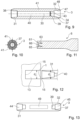
- Figure 1 shows a first object 1 with a proximal surface 11 and with a blind hole 13 having a mouth in the proximal surface 11 and having a bottom face 14 and a circumferential surface 15.
- the first object here is illustrated to be a board of a wood composite material, with the proximal surface being a large-side surface of the board.
- the teaching referring to the depicted figures is applicable to first and second objects of any shape, and to openings having any position, including blind holes in a small-side surface of a board.
- Fig. 1 also illustrates a joining element 3 being generally hollow and tube-shaped, so that an inner hollow space 40 is formed, and for example essentially symmetrical about a proximodistal axis 30, with the possible exception of energy directing ribs extending along the outer surface, as described hereinafter.
- a thickness of the tube forming the joining element 3 is continuously reduced towards the distal and proximal ends, i.e. it tapers off towards distally and proximally, so that the distal end 33 and the proximal end 34 each form an edge.
- the joining element is asymmetrical with respect to a middle plane perpendicular to the proximodistal axis 30 in that a distal portion 31 and a proximal portion 32 are shaped differently.
- the joining element may also be symmetrical with respect to this plane.
- Both, the distal portion 31 and the proximal portion 32 each form a crown for anchoring the joining element in the first object 1 and a second object 2 as described hereinafter.
- Figure 1 also illustrates a tool being a first sonotrode 6.
- the first sonotrode 6 forms a distal end face 61 and a distal recess 63 in the distal end face, which distal recess 63 has a shape adapted to the proximal portion 32 of the joining element 3 so as to receive the proximal portion.
- Figure 4 shows a detail of the proximal portion 32 of the joining element and of a distal end portion of the sonotrode 6.
- a proximally facing inner shoulder forms an abutment face 37.
- an inner portion 64 of the sonotrode presses against the abutment face, whereby the pressing force and vibration energy may be coupled into the joining element without the proximal crown that is proximally of the abutment face 37 and that is received in the distal recess 63 being deformed.
- the region around the abutment face thereby serves as force and energy receiving zone.
- abutment face 37 is illustrated to be perpendicular to the proximodistal axis. It would, however, also be an option to configure an abutment face to be slightly inclined, forming an outward or inward taper, whereby during the process the pressing force generates a slight inward or outward force on the joining element, respectively.
- the abutment face may have any shape suitable for absorbing the pressing force and, if the tool is a sonotrode, for transmitting, together with the outcoupling face of the sonotrode, the mechanical vibration energy.
- the sonotrode is used to press the joining element against the first object with the distal end abutting against the bottom face 14 until a flow portion 36 of the thermoplastic material of the joining element becomes flowable and is pressed into structures of the first object around the bottom face.
- the joining element is anchored in the first object by a positive-fit connection, substantially as for example described in WO 98/42988 .
- Fig. 2 also schematically illustrates a support 7.
- the support may be a non-vibrating support, such as for example formed by a working table, in which configuration the proximodistal axis would be oriented vertically, or by a different stationary or movable non-vibrating element.
- the support may itself be capable of coupling vibration energy into the assembly and therefore form a sonotrode itself.
- the tool instead of being a sonotrode, as illustrated in all embodiments herein, the tool could also serve as mere pressing tool.
- Figure 3 shows the assembly of the first object 1 and the joining element 3 anchored therein, together with a second object 2.
- the second object has a second blind hole 23 having a mouth in the distal surface 21.
- the second object is placed relative to the first object with the second object distal surface 21 facing the first object proximal surface 11 and with the proximal portion 32 at least partially inserted in the second blind hole 23.
- this assembly of the two objects with the joining element positioned in the blind holes is placed between a sonotrode 106 and a support 7.
- the sonotrode may be the first sonotrode 6 as used in the previous step of anchoring the joining element in the first object, or, as shown in Fig.
- the support 7 may be a same support or may be a different support - for example depending on whether or not the first object is moved from a first to a second stage between the steps of anchoring the connector and of joining the second object.
- the support 7 may be a non-vibrating support, or it may be vibrating.
- the support 7 may be a working table or similar.
- the configuration in this step is symmetrical, with the support 7 being a sonotrode acting from one horizontal side and the (second) sonotrode acting from an opposite horizontal side.
- the proximal end of the joining element 3 is pressed against the bottom face 24 of the second blind hole 23. Due to the mechanical vibration energy coupled into the second sonotrode 106 at the same time, a (second) flow portion 37 of the joining element becomes flowable and is pressed into structures of the second object.
- the fact that the proximal end of the joining element forms a proximal crown ending in the proximal edge and thereby has energy directing properties ensures that energy absorption primarily takes place at the proximal end of the connector. It is possible that also at the distal end of the connector there is some energy absorption leading to a heating of the thermoplastic material also there.
- a vibration generating apparatus control may be configured to detect the situation in which a further advance movement of the sonotrode relative to the first object towards distally is not possible anymore and to automatically stop the vibration energy input then.
- the apparatus may be configured to exert an after-pressure for some time, for example for 0.3-3 s, to allow the thermoplastic material to become harder to some extent before the sonotrode is removed.
- the result of the process will be the first and second objects being connected by the joining element as a kind of hidden dowel, in an efficient process and with superb anchoring strength.
- Figure 3 illustrates a further possible design criterion applicable to any embodiment.
- the dimension of the joining element 3 and the anchoring depth achieved in the first anchoring step on the one hand and the depths of the blind holes 13, 23 in the first and second objects on the other hand define a width d 1 of the gap.
- This width d 1 of the gap may be chosen in relation to an axial extension d 2 of the proximal portion (extension between the abutment face 37 and the proximal end 34).
- the width of the gap may be approximately equal to and for example slightly larger than this axial extension.
- the entire crown will have penetrated into material of the second object so as to ensure a secure and reproducible anchoring.
- Figure 5 illustrates the proximal portion 32 of the joining element together with of a distal end portion of a variant of the first sonotrode 6.
- the first sonotrode has a distal end of a reduced diameter fitting into an interior of the proximal end of the joining element so as to cooperate with the abutment face 37.
- the first sonotrode 6 does not need a recess for accommodating the crown of the joining element.
- the abutment face 37 is not an inner shoulder but an outer shoulder. While the configuration with an inner shoulder forming the abutment face has the advantages of the crown (and the proximal edge 34) having a potentially larger diameter with the possibility of having more material liquefied and of an outer surface of the proximal portion contributing to the anchoring (see hereinafter), nevertheless there may be configurations in which the abutment surface forming an outer shoulder may be advantageous, too.
- the receiving opening 63 is illustrated to be shaped so that there is substantially no physical contact between the proximal crown of the joining element and the inner surfaces of the receiving opening.
- Figure 7 depicts an alternative embodiment in which the shapes of the receiving opening 63 and the proximal portion 32 of the joining element are adapted to each other so that the crown exactly fits into the receiving opening. This may lead to a more intimate contact between the sonotrode and the joining element and may ultimately enhance an efficiency of the product. Additionally, the relative positions of the sonotrode and the joining element during the process are defined more precisely, and the risk of causing damages on the proximal end of the joining elements during the process is thereby reduced.
- a dedicated shape of the receiving opening of the sonotrode may also be used to deliberately bring the distal portion of the joining element into such shape. This is schematically illustrated (in somewhat exaggerated manner) in Figure 8 .
- the joining element is illustrated to have a blunt proximal end, whereas the receiving opening 63 has a shape that corresponds to the shape of a tapering crown ending in an edge.
- thermoplastic material of the proximal end will be caused to soften and to flow relative to the sonotrode, whereby the receiving opening (or at least an inner, proximal part of it) serves as a mold for shaping the joining element for the subsequent step of being connected to the second object.
- a receiving opening of the sonotrode serves as a mold may be advantageous especially if the crown is relatively thin compared to its axial extension, i.e. if it is delicate. This may for example be the case if the second object is comparably soft or itself of a delicate structure, whereby the energy absorbed during the second anchoring step is limited, but nevertheless a sufficient anchoring depth is needed. In a situation with a delicate crown shape, a pre-made proximal crown capable of vibrating freely could become damaged already in the first anchoring step. The approach of causing a receiving opening of the sonotrode to serve as a mold deals with this issue in an efficient manner.
- Figure 9 shows a longitudinal section of a joining element 3
- Figure 10 shows a view on this joining element from a proximal direction.
- the joining element 3 has the following characteristics, which are independent of each other, i.e. which can be realized individually or in combinations:
- the removal of the first sonotrode after anchoring the joining element relative to the first object may especially be an issue if the shape of the receiving opening 63 is adapted to the proximal portion 32 of the joining element and/or is used to shape this proximal portion, as described hereinbefore.
- Figure 11 shows an example of a sonotrode having a shape adapted to the shape of the joining element of Figs. 9 and 10 .
- the sonotrode in addition to an outcoupling face 65 that cooperates with the shoulder 37 forming the abutment face (or a proximal portion thereof), the sonotrode has a second outcoupling face 66 located centrally with respect to the axis, which second outcoupling face is positioned to be pressed against the partition member 43 (if any) or a second shoulder of the joining element.
- the sonotrode of Fig. 11 works independent of the existence of the partition member or such second shoulder, though.
- the outcoupling face 65 and for example also the (optional) second outcoupling face 66 is/are offset towards proximally with respect to the distal end face 61 in the depicted embodiment.
- Figure 12 illustrates the principle that it is not necessary for the joining element to be positioned to rest against a bottom face of the blind opening 13.
- the opening in the first object 1 does not even have to be a blind opening.
- the opening is illustrated as a deep blind opening having a diameter d r .
- the dimension of the joining element are adapted for there to be a press-fit (interference fit) if the joining element's distal section is inserted into the opening.
- an outer diameter d j is slightly larger than the diameter d r of the opening.
- Figure 13 schematically illustrates a further embodiment of a joining element, which further embodiment has the following characteristics that differ from characteristics of the joining element of Figs. 9 and 10 and that are independent of each other:
- Figures 14 and 15 very schematically illustrate the fact that the approach according to the present invention is especially suited for configurations in which the first and second objects have different properties in terms of material composition, shape, dimension, orientation etc.
- the openings - being blind openings - for the two joining elements 3 are in a small-side face of the first object and in a large-side face of the second object-respectively.
- Figs. 14 and 15 also very schematically illustrates the principle that at least the second anchoring step, in which the first and second objects are pressed against each other, with the joining element(s) already being anchored relative to the first object, may be a parallel process, carried out for a plurality of (two in Figs. 14/15 ) joining elements at the same time.
- a parallel process is an option for the first anchoring step, too, especially if not carried out by a handheld tool.
- a plurality of sonotrodes for example one sonotrode per joining element
- one sonotrode may be used simultaneously.
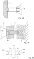
- Figure 16 shows a first object 1 that is a lightweight building element having a first, proximal outer building layer 101, a second, distal outer building layer 102 and an interlining layer 103 having a density and material stiffness substantially smaller than densities/stiffnesses of the outer building layers 101, 102.
- the first object in does not have an opening.
- the joining element is pushed through a surface of the first object.
- the distal edge 33 may punch out a portion of the first outer building layer 101, with or without mechanical vibration energy being input during the punching, substantially as described in WO 2017/162693 .
- the first object is a lightweight building element having a sandwich structure, the distal end of the joining element is used to pierce through the first outer building layer.
- the joining element advances towards distally into material of the first object and thermoplastic material of the distal portion liquefies in contact with structures of the first outer building layer, the interlining layer and/or the second outer building layer.
- Figure 17 shows the resulting arrangement, together with the second object 2 and a second sonotrode 106.
- the second object 2 is a lightweight building element with first and second outer building layers 201, 202 and an interlining layer 203 of lower density and strength. Also the second object 2 is shown without any opening.
- the reverse situation (the first object having the first outer building layer locally removed, whereas the second object does not) is possible also.
- the materials of the first and second objects were illustrated to be hard and dimensionally stable (with the possible exception of the interlining layer 103 of the lightweight building element in the example of Fig. 16 ). This is not a necessity.
- Figure 18 illustrates the first object 1 as a comparably soft foam, for example an Expanded Polypropylene (EPP) foam.
- EPP Expanded Polypropylene
- the distal end of the joining element may then have accordingly adapted structure for anchoring in softer compressible material, for example substantially as described in WO 2018/ 85, for example referring to Fig. 4-9 , 28, 34-47.
- the blind hole in the first object may have a reduced depth for taking into account the compression of the first object during the first anchoring step; depending on the situation, the blind hole in the first object may even be omitted.
- Figure 19 shows a variant in which instead of the first object, the second object 2 is of a comparably softer material, here illustrated to be a fibrous material. In this, it may be the proximal end of the joining element that has an accordingly adapted structure, for example as described in WO 2018/ 85, for example referring to Fig. 4-9 , 28, 34-47.
- a configuration as illustrated in Fig. 19 with the second object being of a softer material than the first object is at the same time an example of an embodiment in which the vibration energy for the second anchoring step is coupled into the assembly from the first object side, as illustrated by the (second) sonotrode 106 being pressed against the backside (distal surface) of the first object, while the assembly is pressed against a non-vibrating support 7 that is proximally of the second object 2.
- the vibration in this is coupled through the first object 1 and the joining element 3 to the interface between the joining element 3 and the second object 2.
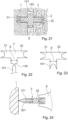
- Figure 20 shows a connector.
- the connector has a distal portion 31 and a proximal portion 32, substantially as described hereinbefore, and further has a laterally protruding spacer portion 131.
- the spacer portion 131 may be used to define a remaining gap between the first and second objects 1, 2.
- the spacer portion stops the movement of the first and second objects towards each other.
- the width of the remaining gap corresponds to a thickness of the spacer portion.
- An adhesive 140 may be applied prior to the step of pressing the first and second objects against each other (or also thereafter), whereby the remaining gap serves as adhesive gap.
- Figure 22 schematically illustrates a joining element 3 with a distal portion 31 and a proximal portion 32, substantially as described hereinbefore, and further with a lateral hinge 150 wo which a further object or structure (not shown) may be attached via a swiveling portion 151.
- a hinge may also be present between the distal portion and the proximal portion, if in a neutral position (distal portion and proximal portion aligned) the hinge provides sufficient axial stiffness for the (second or only) anchoring step to take place.
- the first and second objects may be connected to each other in a swiveling manner, which may have interesting applications for door, window or furniture manufacturing.
- Figure 23 very schematically illustrates the possibility of providing the joining element with a further connecting structure 161 for attaching a third object to the assembly of the first and second objects.
- the further connecting structure is illustrated as a further anchoring structure of the kind of the distal and proximal portions 31, 32.
- any connector structure may be used, including conventional structures, such as a thread etc.
- the arrow s illustrates the width of the spacer portion defining the width of the remaining gap.
- the configuration of Figure 24 comprises a first object 1, a joining element 3 and a sonotrode 6 for carrying out the first anchoring step in a method according to the even further concept.
- the joining element comprises a distal portion 311 that is metallic and a proximal portion 32 that is thermoplastic and that may be configured substantially as described for joining elements in this text.
- the first anchoring step is carried out substantially as described in WO 2016/071 335 , but with a sonotrode that abuts against an abutment face of the joining element, which abutment face is distally of the proximal end, similar to the first aspect.
- the sonotrode 6 and the proximal portion 32 may be shaped and configured as in any embodiment of the first aspect, whereas the distal portion 311 is different and may have a structure and configuration as in any embodiment of the second object described in WO 2016/071 335 .
- the second anchoring step is then carried out as in the first aspect. All options and features that relate to the second anchoring step according to the invention and all features and options that relate to the proximal portion of the joining element used for the invention apply as options equally to the even further concept.
Landscapes
- Engineering & Computer Science (AREA)
- Mechanical Engineering (AREA)
- General Engineering & Computer Science (AREA)
- Life Sciences & Earth Sciences (AREA)
- Wood Science & Technology (AREA)
- Chemical & Material Sciences (AREA)
- Composite Materials (AREA)
- Lining Or Joining Of Plastics Or The Like (AREA)
Claims (14)
- Verfahren zum Verbinden eines ersten (1) und eines zweiten (2) Objekts mit Hilfe eines Verbindungselements (3), wobei das Verfahren die folgenden Schritte umfasst:- Bereitstellen des ersten Objekts (1);- Bereitstellen des Verbindungselements (3), wobei sich das Verbindungselement zwischen einem distalen Ende (33) und einem proximalen Ende (34) erstreckt und ein thermoplastisches Material umfasst;- Positionieren des Verbindungselements (3) relativ zu dem ersten Objekt (1);- Verwenden eines Werkzeugs (6), um das Verbindungselement (3) in distaler Richtung relativ zum ersten Objekt (1) zu drücken, während Energie in das erste Objekt (1) und/oder das Verbindungselement (3) eingekoppelt wird, bis ein erster Abschnitt des thermoplastischen Materials, der zu einem distalen Abschnitt (31) des Verbindungselements (3) gehört, wobei der distale Abschnitt (31) das distale Ende (33) umfasst, fliessfähig gemacht wird und in eine Struktur des ersten Objekts (1) fliessen gelassen wird, um nach erneuter Verfestigung eine Verankerung des distalen Abschnitts (31) des Verbindungselements (3) in dem ersten Objekt (1) zu ergeben;
wobei während des Schritts des Einkoppelns der Energie in das erste Objekt (1) und/oder das Verbindungselement (3) eine Druckfläche des Werkzeugs (6) gegen eine Widerlagerfläche (37) des Verbindungselements (3) stösst, wobei sich die Widerlagerfläche (37) distal vom proximalen Ende (34) befindet;- Bereitstellen des zweiten Objekts (2);- nachdem der erste Teil des thermoplastischen Materials in eine Struktur des ersten Objekts (1) fliessen gelassen wurde, das zweite Objekt (2) relativ zum ersten Objekt (1) platziert wird;- und- das erste (1) und das zweite (2) Objekt gegeneinander gepresst werden, während mechanische Vibrationsenergie in mindestens eines der ersten und zweiten Objekte (1, 2) eingekoppelt wird, bis ein zweiter Teil des thermoplastischen Materials, der zu einem proximalen Teil (32) des Verbindungselements (3) gehört, wobei der proximale Teil (32) das proximale Ende (34) umfasst, fliessfähig gemacht wird und in eine Struktur des zweiten Objekts (2) fliesst, um nach erneuter Verfestigung eine Fixierung zwischen dem Verbindungselement (3) und dem zweiten Objekt (2) zu ergeben- dadurch gekennzeichnet, dass das zweite Objekt (2) eine zweite Öffnung aufweist, die ein Sackloch (23) ist, dass in dem Schritt des Anordnens des zweiten Objekts (2) relativ zu dem ersten Objekt (1) das zweite Objekt (2) so platziert wird, dass der vorstehende proximale Abschnitt (32) des Verbindungselements (3) in die zweite Öffnung (2) eingeführt wird, und dass der Schritt des Aneinanderpressens des ersten (1) und des zweiten (2) Objekts bewirkt, dass das proximale Ende (34) des Verbindungselements (3) gegen eine Bodenfläche (24) der zweiten Öffnung (2) gepresst wird. - Verfahren nach Anspruch 1, wobei in dem Schritt des Bereitstellens des ersten Objekts (1) das erste Objekt eine erste Öffnung aufweist, die ein Sackloch (13) ist, und wobei in dem Schritt des Positionierens des Verbindungselements (3) relativ zu dem ersten Objekt (1) das Positionieren so erfolgt, dass der distale Abschnitt (31) in die erste Öffnung (1) eingeführt wird und der proximale Abschnitt (32) von dem ersten Objekt (1) vorsteht, und wobei eine Summe der Tiefen der ersten und der zweiten Öffnung (13, 23) kleiner ist als eine proximodistale Länge des Verbindungselements (3) und wobei der Schritt des Verwendens des Werkzeugs (6), um das Verbindungselement (3) in distaler Richtung zu drücken, das Drücken des distalen Endes (33) des Verbindungselements (3) gegen eine Bodenfläche der ersten Öffnung (13) umfasst.
- Verfahren nach einem der vorhergehenden Ansprüche, wobei nach dem Schritt des Anordnens des zweiten Objekts (2) relativ zum ersten Objekt (1) ein Spalt zwischen dem ersten und dem zweiten Objekt verbleibt, wobei als Ergebnis des Schritts des Aneinanderpressens des ersten (1) und des zweiten (2) Objekts, während mechanische Vibrationsenergie einwirkt, der Spalt geschlossen wird, oder wobei nach dem Schritt des Anordnens des zweiten Objekts relativ zum ersten Objekt (2, 1) ein Spalt zwischen dem ersten und dem zweiten Objekt (1, 2) verbleibt, wobei als Ergebnis des Schritts des Aneinanderpressens des ersten und des zweiten Objekts, während mechanische Vibrationsenergie einwirkt, eine Breite des Spalts von einer Anfangsbreite auf eine Endbreite verringert wird, wobei die Endbreite von Null verschieden ist.
- Verfahren nach einem der vorhergehenden Ansprüche, wobei das Verbindungselement (3) einen seitlich vorstehenden Abstandshalterabschnitt (131) aufweist und wobei der Schritt des Aneinanderpressens des ersten und des zweiten Objekts (1, 2) so lange ausgeführt wird, bis sowohl das erste als auch das zweite Objekt an dem Abstandshalterabschnitt (131) anliegen, wodurch der Abstandshalterabschnitt die Endbreite festlegt, und/oder wobei das Verfahren ferner das Aufbringen eines Klebstoffs zwischen dem ersten und dem zweiten Objekt (1, 2) umfasst und das Verfahren ferner das Aushärtenlassen des Klebstoffs in dem Spalt mit der Endbreite umfasst.
- Verfahren nach einem der vorhergehenden Ansprüche, wobei die in das erste Objekt (1) und/oder das Verbindungselement (3) eingekoppelte Energie mechanische Schwingungsenergie ist, und wobei das Werkzeug (6) eine Sonotrode ist, wobei die Pressfläche eine Auskopplungsfläche (65) ist, und wobei in dem Schritt des Einkoppelns von Energie in das erste Objekt (1) und/oder das Verbindungselement (3) mindestens ein Bruchteil der mechanischen Schwingungsenergie durch die Sonotrode (6) in das Verbindungselement eingekoppelt wird.
- Verfahren nach einem der vorhergehenden Ansprüche, wobei die Widerlagerfläche eine Schulter (37) des Verbindungselements (3) umfasst und wobei die Schulter beispielsweise eine Innenschulter ist.
- Verfahren nach einem der vorhergehenden Ansprüche, wobei das Verbindungselement (3) proximal der Widerlagerfläche (37) eine proximale Krone aus thermoplastischem Material umfasst und/oder wobei das Verbindungselement (3) eine distale Krone umfasst und/oder wobei das Verbindungselement einen proximalen klingenartigen Vorsprung, der in einer Kante am proximalen Ende (34) endet, und/oder einen distalen klingenartigen Vorsprung, der in einer Kante am distalen Ende (33) endet, aufweist.
- Verfahren nach einem der vorhergehenden Ansprüche, wobei das Verbindungselement (3) rohrförmig und hohl ist.
- Verfahren nach einem der vorhergehenden Ansprüche, wobei das Verbindungselement (3) eine Vielzahl von Energierichtungsrippen (41) aufweist, die von einer Aussenfläche vorstehen, und wobei beispielsweise die Energierichtungsrippen (41) in einer axialen Richtung verlaufen oder schraubenförmig um die Aussenfläche verlaufen, und/oder wobei infolge der Positionierung des Verbindungselements (3) relativ zum ersten Objekt (1) die Energierichtungsrippen (41) in physischem Kontakt mit einer Umfangswand der ersten Öffnung (13) stehen und während des Schritts der Verwendung des Werkzeugs (6), um das Verbindungselement (3) in distaler Richtung zu drücken, wird thermoplastisches Material des Verbindungselements (3) dazu gebracht, in Strukturen des ersten Objekts (1) auch in der Nähe der Umfangswand der ersten Öffnung (13) zu fliessen, und/oder wobei als Ergebnis des Anordnens des zweiten Objekts (2) relativ zum ersten Objekt (1) die Energierichtungsrippen (41) in physischem Kontakt mit einer Umfangswand der zweiten Öffnung (2) sind, und während des Schritts des Gegeneinanderpressens des ersten und zweiten Objekts (1, 2) thermoplastisches Material des Verbindungselements (3) in Strukturen des zweiten Objekts (2) auch in der Nähe der Umfangswand der zweiten Öffnung (23) fliessen gelassen wird.
- Verfahren nach einem der vorhergehenden Ansprüche, wobei das Werkzeug (6) eine distale Aussparung (63) mit einer Öffnung in einer distalen Werkzeugendfläche (61) aufweist und wobei während des Schritts des Verwendens des Werkzeugs (6), um das Verbindungselement (3) in distaler Richtung zu drücken, der proximale Abschnitt (32) des Verbindungselements (3) in der distalen Aussparung (63) aufgenommen wird, wobei die distale Aussparung (63) optional eine Form aufweist, die an eine Form des proximalen Abschnitts (32) des Verbindungselements (3) angepasst ist, und/oder wobei das Werkzeug (6) einen vorstehenden Abschnitt (62) aufweist, der sich während des Schritts des Verwendens des Werkzeugs (6), um das Verbindungselement (3) in distaler Richtung zu drücken, über mindestens einen Teil des proximalen Abschnitts (32) des Verbindungselements (3) hinaus erstreckt.
- Verfahren nach einem der vorhergehenden Ansprüche, das den Schritt des Formens des proximalen Abschnitts (32) des Verbindungselements (3) während des Schritts des Verwendens des Werkzeugs (6), um das Verbindungselement (3) durch die gemeinsame Wirkung der Druckkraft und der Energie in distaler Richtung zu drücken, umfasst, wobei beispielsweise der Schritt des Formens des proximalen Abschnitts (32) des Verbindungselements (3) das Formen des proximalen Abschnitts (32) umfasst, um einen klingenartigen Vorsprung und/oder eine Krone in Umfangsrichtung um einen zentralen Hohlraum (40) herum zu bilden, wobei die Krone beispielsweise am proximalen Ende (34) eine durchgehende Kante bildet und/oder wobei sich der mindestens eine klingenartige Vorsprung oder die Krone in einer unterbrochenen Weise um den zentralen Hohlraum (40) herum erstreckt und eine Vielzahl von Zähnen aufweist, die um den zentralen Hohlraum (40) herum angeordnet sind.
- Verfahren nach einem der vorhergehenden Ansprüche, bei dem nach dem Schritt des Verwendens des Werkzeugs (6), um das Verbindungselement (6) in distaler Richtung zu drücken, und vor dem Schritt des Anordnens des zweiten Objekts (2) relativ zu dem ersten Objekt (1) das Werkzeug (6) von dem Verbindungselement (3) gelöst wird, und bei dem das Lösen des Werkzeugs (6) durch mindestens eines von einem Luftstoss, einem Ausstosskolben, der Kopplung von Vibrationsenergie in das Werkzeug unterstützt wird.
- Ein Teilesatz zur Durchführung des Verfahrens gemäss einem der vorhergehenden Ansprüche, wobei der Teilesatz eine erste Sonotrode (6) umfasst, die als Werkzeug (6) dient, und mindestens ein Verbindungselement (3), wobei sich das Verbindungselement zwischen einem distalen Ende (33) und einem proximalen Ende (34) erstreckt und zumindest in einem proximalen Abschnitt (32), der das proximale Ende (34) aufweist, und in einem distalen Abschnitt (31), der das distale Ende (33) aufweist, ein thermoplastisches Material umfasst, wobei der distale Abschnitt (31) des Verbindungselements (3) eine distale Krone umfasst, die in einer distalen Kante (33) endet, und wobei das proximale Ende (34) und das distale Ende (33) beide mindestens eine thermoplastische Kante oder Spitze mit energierichtenden Eigenschaften bilden, und das Verbindungselement (3) ferner eine proximal gerichtete Widerlagerfläche (37) distal des proximalen Endes (34) umfasst, wobei sich die Sonotrode (6) zwischen einem proximalen Sonotrodenende und einem distalen Sonotrodenende erstreckt, eine distal gerichtete Auskopplungsfläche (65) umfasst und so angepasst ist, dass sie aus proximaler Richtung mit dem Verbindungselement (3) in Kontakt gebracht werden kann, so dass die Auskopplungsfläche (65) in physischem Kontakt mit der Widerlagerfläche (37) steht, um mechanische Schwingungen über die Auskopplungsfläche (65) in das Verbindungselement (3) einzukoppeln, um den distalen Abschnitt (31) zu verflüssigen, indem er gegen eine Bodenfläche (13) einer Öffnung in einem ersten Objekt gedrückt wird.
- Fügeelement zur Durchführung des Verfahrens gemäss einem der Ansprüche 1-12, wobei sich das Fügeelement (3) zwischen einem distalen Ende (33) und einem proximalen Ende (34) erstreckt und zumindest in einem proximalen Abschnitt (32), der das proximale Ende (34) aufweist, und in einem distalen Abschnitt (31), der das distale Ende (33) aufweist, ein thermoplastisches Material umfasst, wobei der distale Abschnitt (33) des Verbindungselements (3) eine distale Krone umfasst, die in einer distalen Kante (33) endet, und wobei das distale Ende (33) mindestens eine thermoplastische Kante oder Spitze mit energierichtenden Eigenschaften bildet und der proximale Abschnitt (32) als eine proximale Krone aus dem thermoplastischen Material geformt ist, wobei die proximale Krone in einer proximalen Kante (34) endet, und das Verbindungselement (3) ferner distal von der proximalen Krone eine Widerlagerfläche (37) aufweist, wobei die Schulter ein in proximaler Richtung weisender Anschlag für eine Auskopplungsfläche einer Sonotrode (6) ist.
Priority Applications (1)
| Application Number | Priority Date | Filing Date | Title |
|---|---|---|---|
| SI202130332T SI4182152T1 (sl) | 2020-07-16 | 2021-07-16 | Združevanje dveh predmetov |
Applications Claiming Priority (2)
| Application Number | Priority Date | Filing Date | Title |
|---|---|---|---|
| CH8812020 | 2020-07-16 | ||
| PCT/EP2021/069930 WO2022013415A1 (en) | 2020-07-16 | 2021-07-16 | Joining two objects |
Publications (2)
| Publication Number | Publication Date |
|---|---|
| EP4182152A1 EP4182152A1 (de) | 2023-05-24 |
| EP4182152B1 true EP4182152B1 (de) | 2025-05-14 |
Family
ID=72145194
Family Applications (1)
| Application Number | Title | Priority Date | Filing Date |
|---|---|---|---|
| EP21745792.8A Active EP4182152B1 (de) | 2020-07-16 | 2021-07-16 | Verbinden zweier objekte |
Country Status (6)
| Country | Link |
|---|---|
| US (1) | US12560190B2 (de) |
| EP (1) | EP4182152B1 (de) |
| CN (1) | CN116171217A (de) |
| PL (1) | PL4182152T3 (de) |
| SI (1) | SI4182152T1 (de) |
| WO (1) | WO2022013415A1 (de) |
Families Citing this family (1)
| Publication number | Priority date | Publication date | Assignee | Title |
|---|---|---|---|---|
| ES3060185T3 (en) * | 2021-07-02 | 2026-03-25 | Multimaterial Welding Ag | Connector element and method of bonding such connector element to a substrate |
Family Cites Families (16)
| Publication number | Priority date | Publication date | Assignee | Title |
|---|---|---|---|---|
| JPH03297629A (ja) * | 1990-04-18 | 1991-12-27 | Mitsubishi Heavy Ind Ltd | 熱可塑複合材構造物の製造方法 |
| CH692091A5 (de) * | 1994-07-01 | 2002-01-31 | Woodwelding Ag | Verfahren zum Zusammenfügen von Teilen aus Holz oder aus holzähnlichen Materialien. |
| AU744974B2 (en) | 1997-03-21 | 2002-03-07 | Woodwelding Ag | Process for anchoring connecting elements in a material with pores or cavities and connecting elements therefor |
| EP1614525A1 (de) | 2004-07-07 | 2006-01-11 | Woodwelding AG | Verfahren zum Verbinden von zwei Teilen und entsprechendes Verbindungsteil |
| US8167347B2 (en) * | 2009-08-24 | 2012-05-01 | Toyota Motor Engineering & Manufacturing North America, Inc. | Three panel heat stake structure |
| DE102009044210A1 (de) | 2009-10-08 | 2011-04-28 | Hettich-Heinze Gmbh & Co. Kg | Dübel und Verfahren zur Montage eines Dübels in eine Leichtbauplatte |
| EP2920471B1 (de) | 2012-11-13 | 2020-05-13 | WoodWelding AG | Verfahren zum verbinden von teilen mit bezug zueinander |
| ES2624624T3 (es) * | 2012-12-05 | 2017-07-17 | Woodwelding Ag | Unión de objetos juntos |
| AU2015265919B2 (en) | 2014-05-28 | 2018-10-04 | Ikea Supply Ag | Method of anchoring a first object in a second object |
| EP3204213B1 (de) | 2014-10-09 | 2024-12-04 | WoodWelding AG | Verfahren zur verankerung eines ersten objekts in einem zweiten objekt |
| MX382183B (es) | 2014-11-04 | 2025-03-13 | Woodwelding Ag | Union de objetos juntos. |
| DE102015210963A1 (de) * | 2015-06-15 | 2016-12-15 | Ejot Gmbh & Co. Kg | Thermoplastischer Reibverbinder |
| WO2017005722A1 (en) * | 2015-07-09 | 2017-01-12 | Woodwelding Ag | Bonding objects together |
| WO2017162693A1 (en) | 2016-03-21 | 2017-09-28 | Multimaterial-Welding Ag | Securing a second object to a first object |
| US10744718B2 (en) * | 2017-09-14 | 2020-08-18 | GM Global Technology Operations LLC | Amalgamation joining methods and apparatuses |
| WO2019197501A1 (en) | 2018-04-10 | 2019-10-17 | Multimaterial-Welding Ag | Connector, and method |
-
2021
- 2021-07-16 CN CN202180051594.7A patent/CN116171217A/zh active Pending
- 2021-07-16 US US18/005,253 patent/US12560190B2/en active Active
- 2021-07-16 EP EP21745792.8A patent/EP4182152B1/de active Active
- 2021-07-16 WO PCT/EP2021/069930 patent/WO2022013415A1/en not_active Ceased
- 2021-07-16 SI SI202130332T patent/SI4182152T1/sl unknown
- 2021-07-16 PL PL21745792.8T patent/PL4182152T3/pl unknown
Also Published As
| Publication number | Publication date |
|---|---|
| US12560190B2 (en) | 2026-02-24 |
| PL4182152T3 (pl) | 2025-10-20 |
| WO2022013415A1 (en) | 2022-01-20 |
| CN116171217A (zh) | 2023-05-26 |
| US20230250840A1 (en) | 2023-08-10 |
| EP4182152A1 (de) | 2023-05-24 |
| SI4182152T1 (sl) | 2025-10-30 |
Similar Documents
| Publication | Publication Date | Title |
|---|---|---|
| KR102354548B1 (ko) | 2개의 물체를 접합하는 방법 | |
| CN115157686B (zh) | 将第二物体锚固至第一物体 | |
| EP3964721B1 (de) | Verbindung von objekten | |
| EP2205429B1 (de) | Verfahren und vorrichtung zur verankerung eines dübels mittels mechanischer schwingungen | |
| EP3487686B1 (de) | Befestigung eines zweiten objekts an einem ersten objekt | |
| EP2314889B1 (de) | Verankerung in einem Baumaterial | |
| US11203166B2 (en) | Securing a second object to a first object | |
| EP3307519B1 (de) | Verankerung in einem leichtbauelement | |
| CN107107476B (zh) | 将物体结合在一起 | |
| CN102256766A (zh) | 锚固联接件的方法和联接件 | |
| CN107530982A (zh) | 将物体结合在一起 | |
| EP4182152B1 (de) | Verbinden zweier objekte | |
| EP4200531B1 (de) | Verbindungselement und verfahren zum verbinden eines solchen verbindungselements mit einem substrat | |
| JPH0222034A (ja) | 異種材料樹脂部品の超音波溶着方法 |
Legal Events
| Date | Code | Title | Description |
|---|---|---|---|
| STAA | Information on the status of an ep patent application or granted ep patent |
Free format text: STATUS: UNKNOWN |
|
| STAA | Information on the status of an ep patent application or granted ep patent |
Free format text: STATUS: THE INTERNATIONAL PUBLICATION HAS BEEN MADE |
|
| PUAI | Public reference made under article 153(3) epc to a published international application that has entered the european phase |
Free format text: ORIGINAL CODE: 0009012 |
|
| STAA | Information on the status of an ep patent application or granted ep patent |
Free format text: STATUS: REQUEST FOR EXAMINATION WAS MADE |
|
| 17P | Request for examination filed |
Effective date: 20230124 |
|
| AK | Designated contracting states |
Kind code of ref document: A1 Designated state(s): AL AT BE BG CH CY CZ DE DK EE ES FI FR GB GR HR HU IE IS IT LI LT LU LV MC MK MT NL NO PL PT RO RS SE SI SK SM TR |
|
| DAV | Request for validation of the european patent (deleted) | ||
| DAX | Request for extension of the european patent (deleted) | ||
| GRAP | Despatch of communication of intention to grant a patent |
Free format text: ORIGINAL CODE: EPIDOSNIGR1 |
|
| STAA | Information on the status of an ep patent application or granted ep patent |
Free format text: STATUS: GRANT OF PATENT IS INTENDED |
|
| RIC1 | Information provided on ipc code assigned before grant |
Ipc: B29K 711/14 20060101ALN20241121BHEP Ipc: B29L 31/00 20060101ALN20241121BHEP Ipc: F16B 15/00 20060101ALN20241121BHEP Ipc: B29C 65/56 20060101ALI20241121BHEP Ipc: B29C 65/60 20060101ALI20241121BHEP Ipc: B29C 65/64 20060101ALI20241121BHEP Ipc: B29C 65/00 20060101ALI20241121BHEP Ipc: B29C 65/34 20060101ALI20241121BHEP Ipc: B29C 65/78 20060101ALI20241121BHEP Ipc: F16B 5/01 20060101ALI20241121BHEP Ipc: F16B 11/00 20060101ALI20241121BHEP Ipc: B29C 65/08 20060101AFI20241121BHEP |
|
| INTG | Intention to grant announced |
Effective date: 20241209 |
|
| GRAS | Grant fee paid |
Free format text: ORIGINAL CODE: EPIDOSNIGR3 |
|
| GRAA | (expected) grant |
Free format text: ORIGINAL CODE: 0009210 |
|
| STAA | Information on the status of an ep patent application or granted ep patent |
Free format text: STATUS: THE PATENT HAS BEEN GRANTED |
|
| AK | Designated contracting states |
Kind code of ref document: B1 Designated state(s): AL AT BE BG CH CY CZ DE DK EE ES FI FR GB GR HR HU IE IS IT LI LT LU LV MC MK MT NL NO PL PT RO RS SE SI SK SM TR |
|
| REG | Reference to a national code |
Ref country code: GB Ref legal event code: FG4D |
|
| REG | Reference to a national code |
Ref country code: CH Ref legal event code: EP |
|
| REG | Reference to a national code |
Ref country code: DE Ref legal event code: R096 Ref document number: 602021030802 Country of ref document: DE |
|
| REG | Reference to a national code |
Ref country code: IE Ref legal event code: FG4D |
|
| REG | Reference to a national code |
Ref country code: SE Ref legal event code: TRGR |
|
| P01 | Opt-out of the competence of the unified patent court (upc) registered |
Free format text: CASE NUMBER: UPC_APP_0205_4182152/2025 Effective date: 20250711 |
|
| REG | Reference to a national code |
Ref country code: NL Ref legal event code: MP Effective date: 20250514 |
|
| PG25 | Lapsed in a contracting state [announced via postgrant information from national office to epo] |
Ref country code: PT Free format text: LAPSE BECAUSE OF FAILURE TO SUBMIT A TRANSLATION OF THE DESCRIPTION OR TO PAY THE FEE WITHIN THE PRESCRIBED TIME-LIMIT Effective date: 20250915 Ref country code: ES Free format text: LAPSE BECAUSE OF FAILURE TO SUBMIT A TRANSLATION OF THE DESCRIPTION OR TO PAY THE FEE WITHIN THE PRESCRIBED TIME-LIMIT Effective date: 20250514 Ref country code: FI Free format text: LAPSE BECAUSE OF FAILURE TO SUBMIT A TRANSLATION OF THE DESCRIPTION OR TO PAY THE FEE WITHIN THE PRESCRIBED TIME-LIMIT Effective date: 20250514 |
|
| PGFP | Annual fee paid to national office [announced via postgrant information from national office to epo] |
Ref country code: DE Payment date: 20250722 Year of fee payment: 5 |
|
| REG | Reference to a national code |
Ref country code: LT Ref legal event code: MG9D |
|
| PG25 | Lapsed in a contracting state [announced via postgrant information from national office to epo] |
Ref country code: GR Free format text: LAPSE BECAUSE OF FAILURE TO SUBMIT A TRANSLATION OF THE DESCRIPTION OR TO PAY THE FEE WITHIN THE PRESCRIBED TIME-LIMIT Effective date: 20250815 Ref country code: NO Free format text: LAPSE BECAUSE OF FAILURE TO SUBMIT A TRANSLATION OF THE DESCRIPTION OR TO PAY THE FEE WITHIN THE PRESCRIBED TIME-LIMIT Effective date: 20250814 |
|
| PG25 | Lapsed in a contracting state [announced via postgrant information from national office to epo] |
Ref country code: NL Free format text: LAPSE BECAUSE OF FAILURE TO SUBMIT A TRANSLATION OF THE DESCRIPTION OR TO PAY THE FEE WITHIN THE PRESCRIBED TIME-LIMIT Effective date: 20250514 |
|
| PGFP | Annual fee paid to national office [announced via postgrant information from national office to epo] |
Ref country code: IT Payment date: 20250829 Year of fee payment: 5 |
|
| REG | Reference to a national code |
Ref country code: AT Ref legal event code: MK05 Ref document number: 1794462 Country of ref document: AT Kind code of ref document: T Effective date: 20250514 |
|
| PG25 | Lapsed in a contracting state [announced via postgrant information from national office to epo] |
Ref country code: BG Free format text: LAPSE BECAUSE OF FAILURE TO SUBMIT A TRANSLATION OF THE DESCRIPTION OR TO PAY THE FEE WITHIN THE PRESCRIBED TIME-LIMIT Effective date: 20250514 |
|
| PGFP | Annual fee paid to national office [announced via postgrant information from national office to epo] |
Ref country code: GB Payment date: 20250724 Year of fee payment: 5 |
|
| PG25 | Lapsed in a contracting state [announced via postgrant information from national office to epo] |
Ref country code: HR Free format text: LAPSE BECAUSE OF FAILURE TO SUBMIT A TRANSLATION OF THE DESCRIPTION OR TO PAY THE FEE WITHIN THE PRESCRIBED TIME-LIMIT Effective date: 20250514 |
|
| PG25 | Lapsed in a contracting state [announced via postgrant information from national office to epo] |
Ref country code: AT Free format text: LAPSE BECAUSE OF FAILURE TO SUBMIT A TRANSLATION OF THE DESCRIPTION OR TO PAY THE FEE WITHIN THE PRESCRIBED TIME-LIMIT Effective date: 20250514 |
|
| PGFP | Annual fee paid to national office [announced via postgrant information from national office to epo] |
Ref country code: FR Payment date: 20250725 Year of fee payment: 5 |
|
| PGFP | Annual fee paid to national office [announced via postgrant information from national office to epo] |
Ref country code: SE Payment date: 20250722 Year of fee payment: 5 |
|
| PG25 | Lapsed in a contracting state [announced via postgrant information from national office to epo] |
Ref country code: RS Free format text: LAPSE BECAUSE OF FAILURE TO SUBMIT A TRANSLATION OF THE DESCRIPTION OR TO PAY THE FEE WITHIN THE PRESCRIBED TIME-LIMIT Effective date: 20250814 |
|
| PG25 | Lapsed in a contracting state [announced via postgrant information from national office to epo] |
Ref country code: IS Free format text: LAPSE BECAUSE OF FAILURE TO SUBMIT A TRANSLATION OF THE DESCRIPTION OR TO PAY THE FEE WITHIN THE PRESCRIBED TIME-LIMIT Effective date: 20250914 |
|
| PG25 | Lapsed in a contracting state [announced via postgrant information from national office to epo] |
Ref country code: LV Free format text: LAPSE BECAUSE OF FAILURE TO SUBMIT A TRANSLATION OF THE DESCRIPTION OR TO PAY THE FEE WITHIN THE PRESCRIBED TIME-LIMIT Effective date: 20250514 |
|
| PGFP | Annual fee paid to national office [announced via postgrant information from national office to epo] |
Ref country code: SI Payment date: 20250710 Year of fee payment: 5 |
|
| PG25 | Lapsed in a contracting state [announced via postgrant information from national office to epo] |
Ref country code: DK Free format text: LAPSE BECAUSE OF FAILURE TO SUBMIT A TRANSLATION OF THE DESCRIPTION OR TO PAY THE FEE WITHIN THE PRESCRIBED TIME-LIMIT Effective date: 20250514 Ref country code: SM Free format text: LAPSE BECAUSE OF FAILURE TO SUBMIT A TRANSLATION OF THE DESCRIPTION OR TO PAY THE FEE WITHIN THE PRESCRIBED TIME-LIMIT Effective date: 20250514 |
|
| PG25 | Lapsed in a contracting state [announced via postgrant information from national office to epo] |
Ref country code: CZ Free format text: LAPSE BECAUSE OF FAILURE TO SUBMIT A TRANSLATION OF THE DESCRIPTION OR TO PAY THE FEE WITHIN THE PRESCRIBED TIME-LIMIT Effective date: 20250514 |
|
| PGFP | Annual fee paid to national office [announced via postgrant information from national office to epo] |
Ref country code: PL Payment date: 20250710 Year of fee payment: 5 |
|
| PG25 | Lapsed in a contracting state [announced via postgrant information from national office to epo] |
Ref country code: EE Free format text: LAPSE BECAUSE OF FAILURE TO SUBMIT A TRANSLATION OF THE DESCRIPTION OR TO PAY THE FEE WITHIN THE PRESCRIBED TIME-LIMIT Effective date: 20250514 |
|
| PG25 | Lapsed in a contracting state [announced via postgrant information from national office to epo] |
Ref country code: SK Free format text: LAPSE BECAUSE OF FAILURE TO SUBMIT A TRANSLATION OF THE DESCRIPTION OR TO PAY THE FEE WITHIN THE PRESCRIBED TIME-LIMIT Effective date: 20250514 |
|
| REG | Reference to a national code |
Ref country code: CH Ref legal event code: H13 Free format text: ST27 STATUS EVENT CODE: U-0-0-H10-H13 (AS PROVIDED BY THE NATIONAL OFFICE) Effective date: 20260224 |
|
| PG25 | Lapsed in a contracting state [announced via postgrant information from national office to epo] |
Ref country code: RO Free format text: LAPSE BECAUSE OF FAILURE TO SUBMIT A TRANSLATION OF THE DESCRIPTION OR TO PAY THE FEE WITHIN THE PRESCRIBED TIME-LIMIT Effective date: 20250514 |
|
| PG25 | Lapsed in a contracting state [announced via postgrant information from national office to epo] |
Ref country code: LU Free format text: LAPSE BECAUSE OF NON-PAYMENT OF DUE FEES Effective date: 20250716 |
|
| PLBE | No opposition filed within time limit |
Free format text: ORIGINAL CODE: 0009261 |
|
| STAA | Information on the status of an ep patent application or granted ep patent |
Free format text: STATUS: NO OPPOSITION FILED WITHIN TIME LIMIT |
|
| REG | Reference to a national code |
Ref country code: CH Ref legal event code: L10 Free format text: ST27 STATUS EVENT CODE: U-0-0-L10-L00 (AS PROVIDED BY THE NATIONAL OFFICE) Effective date: 20260325 |