EP4181520A1 - Automatic ir led control for camera mirror system - Google Patents
Automatic ir led control for camera mirror system Download PDFInfo
- Publication number
- EP4181520A1 EP4181520A1 EP22206810.8A EP22206810A EP4181520A1 EP 4181520 A1 EP4181520 A1 EP 4181520A1 EP 22206810 A EP22206810 A EP 22206810A EP 4181520 A1 EP4181520 A1 EP 4181520A1
- Authority
- EP
- European Patent Office
- Prior art keywords
- led
- state
- roi
- luminance
- controller
- Prior art date
- Legal status (The legal status is an assumption and is not a legal conclusion. Google has not performed a legal analysis and makes no representation as to the accuracy of the status listed.)
- Pending
Links
Images


Classifications
-
- B—PERFORMING OPERATIONS; TRANSPORTING
- B60—VEHICLES IN GENERAL
- B60R—VEHICLES, VEHICLE FITTINGS, OR VEHICLE PARTS, NOT OTHERWISE PROVIDED FOR
- B60R1/00—Optical viewing arrangements; Real-time viewing arrangements for drivers or passengers using optical image capturing systems, e.g. cameras or video systems specially adapted for use in or on vehicles
- B60R1/20—Real-time viewing arrangements for drivers or passengers using optical image capturing systems, e.g. cameras or video systems specially adapted for use in or on vehicles
- B60R1/30—Real-time viewing arrangements for drivers or passengers using optical image capturing systems, e.g. cameras or video systems specially adapted for use in or on vehicles providing vision in the non-visible spectrum, e.g. night or infrared vision
-
- B—PERFORMING OPERATIONS; TRANSPORTING
- B60—VEHICLES IN GENERAL
- B60R—VEHICLES, VEHICLE FITTINGS, OR VEHICLE PARTS, NOT OTHERWISE PROVIDED FOR
- B60R1/00—Optical viewing arrangements; Real-time viewing arrangements for drivers or passengers using optical image capturing systems, e.g. cameras or video systems specially adapted for use in or on vehicles
- B60R1/20—Real-time viewing arrangements for drivers or passengers using optical image capturing systems, e.g. cameras or video systems specially adapted for use in or on vehicles
- B60R1/22—Real-time viewing arrangements for drivers or passengers using optical image capturing systems, e.g. cameras or video systems specially adapted for use in or on vehicles for viewing an area outside the vehicle, e.g. the exterior of the vehicle
-
- H—ELECTRICITY
- H04—ELECTRIC COMMUNICATION TECHNIQUE
- H04N—PICTORIAL COMMUNICATION, e.g. TELEVISION
- H04N23/00—Cameras or camera modules comprising electronic image sensors; Control thereof
- H04N23/60—Control of cameras or camera modules
-
- B—PERFORMING OPERATIONS; TRANSPORTING
- B60—VEHICLES IN GENERAL
- B60R—VEHICLES, VEHICLE FITTINGS, OR VEHICLE PARTS, NOT OTHERWISE PROVIDED FOR
- B60R1/00—Optical viewing arrangements; Real-time viewing arrangements for drivers or passengers using optical image capturing systems, e.g. cameras or video systems specially adapted for use in or on vehicles
- B60R1/20—Real-time viewing arrangements for drivers or passengers using optical image capturing systems, e.g. cameras or video systems specially adapted for use in or on vehicles
- B60R1/22—Real-time viewing arrangements for drivers or passengers using optical image capturing systems, e.g. cameras or video systems specially adapted for use in or on vehicles for viewing an area outside the vehicle, e.g. the exterior of the vehicle
- B60R1/23—Real-time viewing arrangements for drivers or passengers using optical image capturing systems, e.g. cameras or video systems specially adapted for use in or on vehicles for viewing an area outside the vehicle, e.g. the exterior of the vehicle with a predetermined field of view
- B60R1/26—Real-time viewing arrangements for drivers or passengers using optical image capturing systems, e.g. cameras or video systems specially adapted for use in or on vehicles for viewing an area outside the vehicle, e.g. the exterior of the vehicle with a predetermined field of view to the rear of the vehicle
-
- B—PERFORMING OPERATIONS; TRANSPORTING
- B60—VEHICLES IN GENERAL
- B60R—VEHICLES, VEHICLE FITTINGS, OR VEHICLE PARTS, NOT OTHERWISE PROVIDED FOR
- B60R1/00—Optical viewing arrangements; Real-time viewing arrangements for drivers or passengers using optical image capturing systems, e.g. cameras or video systems specially adapted for use in or on vehicles
- B60R1/20—Real-time viewing arrangements for drivers or passengers using optical image capturing systems, e.g. cameras or video systems specially adapted for use in or on vehicles
- B60R1/22—Real-time viewing arrangements for drivers or passengers using optical image capturing systems, e.g. cameras or video systems specially adapted for use in or on vehicles for viewing an area outside the vehicle, e.g. the exterior of the vehicle
- B60R1/28—Real-time viewing arrangements for drivers or passengers using optical image capturing systems, e.g. cameras or video systems specially adapted for use in or on vehicles for viewing an area outside the vehicle, e.g. the exterior of the vehicle with an adjustable field of view
-
- H—ELECTRICITY
- H04—ELECTRIC COMMUNICATION TECHNIQUE
- H04N—PICTORIAL COMMUNICATION, e.g. TELEVISION
- H04N23/00—Cameras or camera modules comprising electronic image sensors; Control thereof
- H04N23/10—Cameras or camera modules comprising electronic image sensors; Control thereof for generating image signals from different wavelengths
- H04N23/11—Cameras or camera modules comprising electronic image sensors; Control thereof for generating image signals from different wavelengths for generating image signals from visible and infrared light wavelengths
-
- H—ELECTRICITY
- H04—ELECTRIC COMMUNICATION TECHNIQUE
- H04N—PICTORIAL COMMUNICATION, e.g. TELEVISION
- H04N23/00—Cameras or camera modules comprising electronic image sensors; Control thereof
- H04N23/56—Cameras or camera modules comprising electronic image sensors; Control thereof provided with illuminating means
-
- H—ELECTRICITY
- H04—ELECTRIC COMMUNICATION TECHNIQUE
- H04N—PICTORIAL COMMUNICATION, e.g. TELEVISION
- H04N23/00—Cameras or camera modules comprising electronic image sensors; Control thereof
- H04N23/60—Control of cameras or camera modules
- H04N23/63—Control of cameras or camera modules by using electronic viewfinders
- H04N23/633—Control of cameras or camera modules by using electronic viewfinders for displaying additional information relating to control or operation of the camera
- H04N23/635—Region indicators; Field of view indicators
-
- H—ELECTRICITY
- H04—ELECTRIC COMMUNICATION TECHNIQUE
- H04N—PICTORIAL COMMUNICATION, e.g. TELEVISION
- H04N23/00—Cameras or camera modules comprising electronic image sensors; Control thereof
- H04N23/70—Circuitry for compensating brightness variation in the scene
- H04N23/71—Circuitry for evaluating the brightness variation
-
- H—ELECTRICITY
- H04—ELECTRIC COMMUNICATION TECHNIQUE
- H04N—PICTORIAL COMMUNICATION, e.g. TELEVISION
- H04N7/00—Television systems
- H04N7/18—Closed-circuit television [CCTV] systems, i.e. systems in which the video signal is not broadcast
-
- B—PERFORMING OPERATIONS; TRANSPORTING
- B60—VEHICLES IN GENERAL
- B60R—VEHICLES, VEHICLE FITTINGS, OR VEHICLE PARTS, NOT OTHERWISE PROVIDED FOR
- B60R2300/00—Details of viewing arrangements using cameras and displays, specially adapted for use in a vehicle
- B60R2300/10—Details of viewing arrangements using cameras and displays, specially adapted for use in a vehicle characterised by the type of camera system used
- B60R2300/103—Details of viewing arrangements using cameras and displays, specially adapted for use in a vehicle characterised by the type of camera system used using camera systems provided with artificial illumination device, e.g. IR light source
-
- B—PERFORMING OPERATIONS; TRANSPORTING
- B60—VEHICLES IN GENERAL
- B60R—VEHICLES, VEHICLE FITTINGS, OR VEHICLE PARTS, NOT OTHERWISE PROVIDED FOR
- B60R2300/00—Details of viewing arrangements using cameras and displays, specially adapted for use in a vehicle
- B60R2300/10—Details of viewing arrangements using cameras and displays, specially adapted for use in a vehicle characterised by the type of camera system used
- B60R2300/106—Details of viewing arrangements using cameras and displays, specially adapted for use in a vehicle characterised by the type of camera system used using night vision cameras
-
- B—PERFORMING OPERATIONS; TRANSPORTING
- B60—VEHICLES IN GENERAL
- B60R—VEHICLES, VEHICLE FITTINGS, OR VEHICLE PARTS, NOT OTHERWISE PROVIDED FOR
- B60R2300/00—Details of viewing arrangements using cameras and displays, specially adapted for use in a vehicle
- B60R2300/80—Details of viewing arrangements using cameras and displays, specially adapted for use in a vehicle characterised by the intended use of the viewing arrangement
- B60R2300/8046—Details of viewing arrangements using cameras and displays, specially adapted for use in a vehicle characterised by the intended use of the viewing arrangement for replacing a rear-view mirror system
Definitions
- the disclosure relates to a CMS system using IR LEDs for night vision.
- IR LEDs can be used to improve visibility for drivers in low light conditions.
- the IR LEDs are controlled so that they are not continuously ON to manage heat.
- Using camera monitor systems with night vision may result in situations where the image displayed in the vehicle to the driver is oversaturated such that the object or person is not clearly visible.
- a camera monitor system includes a camera arm that has a camera with an image capture unit that is configured to capture an image of a desired field of view.
- the system further includes a display that is configured to display the desired field of view, an IR LED that is configured to illuminate at least a portion of the desired field of view, and a controller that is in communication with the image capture unit and the IR LED.
- the controller is configured to select at least first and second regions of interest (ROI) from the captured image.
- the first ROI is indicative of an amount of ambient light.
- the controller is configured to determine a luminance of each of said first and second ROIs.
- the controller is configured to regulate an IR LED state of the IR LED based upon the first ROI luminance, and the controller is configured to adjust the IR LED state based upon the second ROI luminance.
- the first and second ROIs may correspond to different first and second portions of the same image.
- the first ROI may be above a horizon and skyward in the desired field of view.
- the second ROI may be aftward alongside a vehicle that has the camera monitor system.
- the image capture unit may be configured to capture an RGB image.
- the controller may be configured to convert the RGB image of the first and second ROIs to HSV.
- the controller may be configured to turn the IR LED to an ON state from an OFF state of the IR LED, or to an OFF state from the ON state.
- the controller may be configured to change an amount of IR LED illumination other than an entirely ON IR LED state or an entirely OFF IR LED state.
- the controller may be configured to regulate the IR LED state based upon a vehicle operating state.
- the controller may include a switch that has AUTOMATIC and MANUAL positions.
- the controller may be configured to regulate the IR LED state in response to the switch being in the AUTOMATIC position.
- a method of automatically controlling a vehicle night vision system includes the steps of capturing an image in a desired field of view, selecting at least first and second regions of interest (ROI) from the captured image, the first ROI is indicative of an amount of ambient light, determining a luminance of each of said first and second ROIs, the first ROI is indicative of an amount of ambient light, regulating an IR LED state of an IR LED based upon the first ROI luminance, and adjusting the IR LED state based upon the second ROI luminance.
- ROI regions of interest
- the first and second ROIs may correspond to different first and second portions of the same captured image.
- the first ROI may be above a horizon and skyward in the desired field of view.
- the second ROI may be aftward alongside a vehicle that has the night vision system.
- the desired field of view may include both Class II and Class IV views.
- the image capturing step may include capturing an RGB image.
- the luminance determining step may include converting the RGB image of the first and second ROIs to HSV (Hue, Saturation, Value).
- the luminance determining step may include calculating a median of the Value.
- the luminance determining step may include applying a low pass filter to the Value for each of the first and second ROIs.
- the low pass filter for each of the first and second ROIs may be different from one another.
- the luminance determining step may include comparing the HSV Value to a desired luminance.
- the IR LED state regulating step may include changing IR LED state only if the Value exceeds an offset from the desired luminance.
- the IR LED state regulating step may include automatically turning the IR LED to an ON state or an OFF state.
- the IR LED state adjusting step may include turning the IR LED to an ON state from an OFF state of the IR LED, or to an OFF state from an ON state.
- the IR LED state adjusting step may include changing an amount of IR LED illumination other than an entirely ON state or an entirely OFF state of the IR LED.
- the IR LED state regulating step may be performed based upon a vehicle operating state.
- the method may include a switch having AUTOMATIC and MANUAL positions.
- the IR LED state regulating step may be performed in response to the switch being in the AUTOMATIC position.
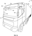
- FIG. 1A and IB A schematic view of a commercial vehicle 10 is illustrated in Figures 1A and IB.
- the vehicle 10 includes a vehicle cab or tractor 12 for pulling a trailer 14. It should be understood that the vehicle cab 12 and/or trailer 14 may be any configuration. Although a commercial truck is contemplated in this disclosure, the disclosed system may also be applied to other types of vehicles.
- the vehicle 10 incorporates a camera monitor system (CMS) 30 ( Fig. 2 ) that has driver and passenger side camera arms 16a, 16b (generally, "16") mounted to the outside of the vehicle cab 12.
- the camera arms 16a, 16b may include conventional mirrors integrated with them as well, although the CMS 30 can be used to entirely replace side view mirrors.
- each side can include multiple camera arms 16, with each arm 16 housing one or more cameras and/or mirrors.
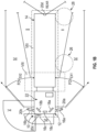
- Each of the camera arms 16a, 16b includes a base 32 that is secured to, for example, the cab 12, as shown in Figure 2 .
- a pivoting arm 34 is supported by the base 34 and may articulate relative thereto either manually or using a power fold mechanism.
- at least one rearward facing camera 20a, 20b (generally, "20") is arranged respectively within each of the camera arms.
- the exterior cameras 20a, 20b respectively provide an exterior field of view FOVEX1, FOVEX2 that each include at least one of the Class II and Class IV views ( Fig. 1B ), which are legal prescribed views in the commercial trucking industry.
- the Class II view on a given side of the vehicle 10 is a subset of the Class IV view of the same side of the vehicle 10.
- both the Class II and Class IV views are provided by a single camera providing a wide-angle view. Multiple cameras also may be used in each camera arm 16a, 16b to provide these views, if desired.
- Class II and Class IV views are defined in European R46 legislation, for example, and the United States and other countries have similar drive visibility requirements for commercial trucks. Any reference to a "Class" view is not intended to be limiting, but is intended as exemplary for the type of view provided to a display by a particular camera.
- Each arm 16a, 16b may also provide a housing that encloses electronics that are configured to provide various features of the CMS 30.
- First and second video displays 18a, 18b are arranged on each of the driver and passenger sides within the vehicle cab 12 on or near the A-pillars to display Class II and Class IV views on its respective side of the vehicle 10, which provide rear facing side views along the vehicle 10 that are captured by the exterior cameras 20a, 20b.
- the Class II and Class IV views may be provided by cropping portions of the image from the wide-angle camera.
- a camera housing 16c and camera 20c may be arranged at or near the front of the vehicle 10 to provide those views ( Fig. 1B ).
- a third display 18c arranged within the cab 12 near the top center of the windshield can be used to display the Class V and Class VI views, which are toward the front of the vehicle 10, to the driver.
- the displays 18a, 18b, 18c (generally, display 18) face a driver region 24 within the cabin 22 where an operator is seated on a driver seat 26.
- the location, size and field(s) of view streamed to any particular display may vary from the configurations described in this disclosure and still incorporate the disclosed invention.
- camera housings can be disposed at the sides and rear of the vehicle 10 to provide fields of view including some or all of the Class VIII zones of the vehicle 10.
- the third display 18c can include one or more frames displaying the Class VIII views.
- additional displays can be added near the first, second and third displays 18a, 18b, 18c and provide a display dedicated to providing a Class VIII view.
- the area behind the trailer is a common blind spot for any vehicle, but particularly for commercial trucks. So, it is desirable to provide the operator some awareness of unseen objects at the rear of the trailer using a sensor, such as a camera 20d, as illustrated in Figure IB.
- a sensor such as a camera 20d
- Challenges to using a camera at the rear of a trailer is the long run of wires that used transmit a video signal to the display in the cab. Dedicated wiring would add significant cost to the system. Additionally, the images must be transmitted with minimal to no latency so objects are displayed in real time.
- a night vision system 30 is shown in Figure 2 .
- the system 30 includes an image capture unit 36 configured to capture a desired field of view for the camera 20.
- the camera 20 is arranged in the pivotal portion 34 of the camera arm 16 which articulates with respect to the fixed, base portion 32 that is secured to the vehicle cab 12.
- Also arranged in the camera arm 16 are one or more IR LEDs 38, 40.
- the IR LEDs may be a single IR LED or an array of multiple IR LEDs that may be regulated together or independently from one another.
- the first IR LED array 38 provides one night vision illumination area 28, and the second array 40 provides another IR LED illumination area 26, which may illuminate alongside the vehicle 10 as shown in Figure IB. It should be understood that a single IR LED or array of IR LEDs may be used rather than the two arrays schematically shown.
- a controller 42 which may be arranged within the vehicle cab 12, is in communication with the image capture unit 36 and the IR LEDs 38, 40.
- the controller 42 may include video processing, which displays the captured image from the image capture unit 36 in a desired format on the display 18, e.g., Class II and Class IV views.
- the controller 42 is in communication with various input and output devices.
- the controller 42 may receive information from the vehicle components through the CAN bus regarding the vehicles operational state.
- a transmission gear position switch 48 may indicate whether the vehicle is in a forward or reverse gear.
- a vehicle speed sensor 50 provides vehicle speed information.
- Another example input device is a switch movable between OFF, AUTOMATIC, and MANUAL positions. In the OFF position, the IR LEDs are switched to an OFF IR LED state and are inoperable. In the MANUAL position, the drive can switch the IR LEDs to an ON IR LED state regardless of whether the IR LEDs would be turned on in the AUTOMATIC operating mode. In the AUTOMATIC position, the controller 42 uses an algorithm 60 described in more detail below and summarized by the method illustrated in Figure 4 .
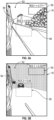
- the display 18 includes at least two regions of interest (ROI) shown as cropped portions of the same image provided by the image capture unit 36. These regions would not be shown on the display; rather, Figures 3A and 3B illustrate where the regions might be located to provide the described functionality. More than two ROIs may be used if desired.
- the controller 42 is configured to determine an average luminance of each of said first and second ROIs 56, 58.
- the luminance values may be normalized between 0 and 1, where 0 is pitch black and 1 is full light.
- An intermediate value of 0.5 may be used as the as a dividing point between day time and night time, for example.
- the 0.5 value may also be used to determine whether there may be oversaturation at night, for example, if the luminance is below 0.5 in the second ROI 58 at night. Other values may be used if desired.
- the first and second ROIs 56, 58 respectively provide portions of the image above the horizon and skyward and aftward alongside the vehicle, for example, along the trailer 14.
- the first ROI 56 is intended to provide an indication of the amount of ambient light, i.e., daytime or nighttime. In the examples shown, an average of the luminance in the portion of the captured image within the first ROI 56 is 0.77 ( Fig. 3A ) indicating daytime, whereas a value of 0.23 ( Fig. 3B ) indicates nighttime.
- the second ROI 58 is intended to capture lighting that may saturate any images or objects in the field of view when the IR LEDs are ON, for example, by a vehicle with headlights are overtaking the tractor/trailer.
- the controller 42 is configured to regulate an IR LED state of the IR LEDs 38 and/or 40 based upon the first ROI luminance. That is, the IR LEDs will be ON at nighttime and OFF during the day.
- the IR LEDs ON time may be limited based upon various use cases, if desired, for example, when the tractor/trailer is in reverse or going at speeds below 5-10 mph.
- both IR LEDs 38, 40 may be used when in reverse and docking for improved visibility, while only one of the IR LEDs may be used when the vehicle is traveling forward.
- the controller 42 is configured to adjust the IR LED state based upon the second ROI luminance, for example, turn the some or all of the IR LEDs OFF or reduce the power to the IR LEDs so they are not fully ON.
- a method 60 or algorithm of automatically controlling the vehicle night vision system is shown in Figure 4 .
- An image in a desired field of view is captured (block 62).
- the desired field of view includes both Class II and Class IV views.
- At least first and second regions of interest (ROI) are selected (e.g., by cropping from a common image) from the captured image (block 64), wherein the first ROI is indicative of an amount of ambient light.
- ROI regions of interest
- the second ROI is positioned to pick up lighting from sources such as passing vehicles that could result in oversaturation.
- a luminance of each of said first and second ROIs is determined (block 66).
- the image capture unit is configured to capture an RGB image.
- the controller is configured to convert the RGB image of the first and second ROIs to HSV (Hue, Saturation, Value).
- the Value (V) is used for luminance.
- One example conversion formula is provided per the following:
- the R,G,B values are divided by 255 to change the range from 0..255 to 0..1:
- R ′ R / 255
- G ′ G / 255
- B ′ B / 255
- the RGB to HSV is done for each pixel in each ROI, and the median V for each ROI is computed to determine the luminance (0 to 1 value) for the particular ROI at that given moment.
- a low pass filter is applied to the HSV Value for each of the first and second ROIs, which filters out high frequency noise or fluctuations in V over time.
- the low pass filter for each of the first and second ROIs is different from one another.
- the second ROI used to detect sources of oversaturation may have a lighter low pass filter than the V from the first ROI because the second ROI's V will likely change more quickly than that derived from the first ROI.
- the filtered V for each ROI is ultimately used to determine the luminance in the ROI for regulating the IR LED states.
- the IR LED state is regulated by changing IR LED state only if the HSV Value exceeds an offset from the desired luminance, providing a hysteresis.
- the IR LEDs automatically may be switched ON and OFF based the V of the first ROI, i.e., controlling the IR LEDs based upon day and nighttime ambient light (block 68). So, the IR LEDs may be switched OFF above 0.5 V in the first ROI, or switched ON below 0.5 V in the second ROI.
- an offset of 0.2 may be used, such that once ON, the IR LEDs are switched off when reaching 0.3 V. Similarly, once the IR LEDs are OFF, they might only be switched ON when reaching 0.7 V. Further regulation of the IR LED state based upon the oversaturation detection of the second ROI (block 70) may employ a different hysteresis, e.g., an offset of 0.1 V so that IR LED regulation is more active based upon the luminance of second ROI.
- the IR LEDs need not only operate in the ON/OFF states. That is, the controller may change an amount of IR LED illumination other than an entirely ON IR LED state or an entirely OFF IR LED state. For example, in oversaturation conditions detected in the second ROI, the controller 42 can reduce the power of the IR LEDs, for example, from 100% power to 30%, 50% or 70% power.
- the controller 42 can be used to implement the various functionality disclosed in this application.
- the controller 42 may include one or more discrete units. Moreover, a portion of the controller 42 may be provided in the vehicle, while another portion of the controller 42 may be located elsewhere.
- a computing device can include a processor, memory, and one or more input and/or output (I/O) device interface(s) that are communicatively coupled via a local interface.
- the local interface can include, for example but not limited to, one or more buses and/or other wired or wireless connections.
- the local interface may have additional elements, which are omitted for simplicity, such as controllers, buffers (caches), drivers, repeaters, and receivers to enable communications. Further, the local interface may include address, control, and/or data connections to enable appropriate communications among the aforementioned components.
- the controller 42 may be a hardware device for executing software, particularly software stored in memory.
- the controller 42 can be a custom made or commercially available processor, a central processing unit (CPU), an auxiliary processor among several processors associated with the controller 42, a semiconductor-based microprocessor (in the form of a microchip or chip set) or generally any device for executing software instructions.
- the memory can include any one or combination of volatile memory elements (e.g., random access memory (RAM, such as DRAM, SRAM, SDRAM, VRAM, etc.)) and/or nonvolatile memory elements (e.g., ROM, hard drive, tape, CD-ROM, etc.). Moreover, the memory may incorporate electronic, magnetic, optical, and/or other types of storage media. The memory can also have a distributed architecture, where various components are situated remotely from one another, but can be accessed by the processor.
- volatile memory elements e.g., random access memory (RAM, such as DRAM, SRAM, SDRAM, VRAM, etc.
- nonvolatile memory elements e.g., ROM, hard drive, tape, CD-ROM, etc.
- the memory can also have a distributed architecture, where various components are situated remotely from one another, but can be accessed by the processor.
- the software in the memory may include one or more separate programs, each of which includes an ordered listing of executable instructions for implementing logical functions.
- a system component embodied as software may also be construed as a source program, executable program (object code), script, or any other entity comprising a set of instructions to be performed.
- the program is translated via a compiler, assembler, interpreter, or the like, which may or may not be included within the memory.
- the disclosed input and output devices that may be coupled to system I/O interface(s) may include input devices, for example but not limited to, a keyboard, mouse, scanner, microphone, camera, mobile device, proximity device, etc. Further, the output devices, for example but not limited to, a display, macroclimate device, microclimate device, etc. Finally, the input and output devices may further include devices that communicate both as inputs and outputs, for instance but not limited to, a modulator/demodulator (modem; for accessing another device, system, or network), a radio frequency (RF) or other transceiver, a telephonic interface, a bridge, a router, etc.
- modem for accessing another device, system, or network
- RF radio frequency
- the processor can be configured to execute software stored within the memory, to communicate data to and from the memory, and to generally control operations of the computing device pursuant to the software.
- Software in memory, in whole or in part, is read by the processor, perhaps buffered within the processor, and then executed.
Landscapes
- Engineering & Computer Science (AREA)
- Multimedia (AREA)
- Signal Processing (AREA)
- Mechanical Engineering (AREA)
- Closed-Circuit Television Systems (AREA)
- Studio Devices (AREA)
Applications Claiming Priority (2)
| Application Number | Priority Date | Filing Date | Title |
|---|---|---|---|
| US202163278635P | 2021-11-12 | 2021-11-12 | |
| US17/979,285 US12330564B2 (en) | 2021-11-12 | 2022-11-02 | Automatic IR LED control for camera mirror system |
Publications (1)
| Publication Number | Publication Date |
|---|---|
| EP4181520A1 true EP4181520A1 (en) | 2023-05-17 |
Family
ID=84332209
Family Applications (1)
| Application Number | Title | Priority Date | Filing Date |
|---|---|---|---|
| EP22206810.8A Pending EP4181520A1 (en) | 2021-11-12 | 2022-11-10 | Automatic ir led control for camera mirror system |
Country Status (4)
| Country | Link |
|---|---|
| US (1) | US12330564B2 (enExample) |
| EP (1) | EP4181520A1 (enExample) |
| JP (1) | JP7792322B2 (enExample) |
| CN (1) | CN116118624A (enExample) |
Families Citing this family (1)
| Publication number | Priority date | Publication date | Assignee | Title |
|---|---|---|---|---|
| DE102023100141A1 (de) * | 2023-01-04 | 2024-07-04 | Man Truck & Bus Se | Sichtsystem für ein Fahrzeug |
Citations (3)
| Publication number | Priority date | Publication date | Assignee | Title |
|---|---|---|---|---|
| JP5003593B2 (ja) * | 2008-05-21 | 2012-08-15 | 株式会社デンソー | 車両用ライト制御装置及び車両用ライト制御プログラム |
| US20190143908A1 (en) * | 2017-11-16 | 2019-05-16 | Magna Electronics Inc. | Vehicle light/display control system using camera |
| US20200267820A1 (en) * | 2019-02-14 | 2020-08-20 | Orlaco Products B.V. | Replacement mirror system with ir led overheating management |
Family Cites Families (2)
| Publication number | Priority date | Publication date | Assignee | Title |
|---|---|---|---|---|
| WO2020157726A1 (en) * | 2019-02-01 | 2020-08-06 | Gentex Corporation | Active infrared illumination for enhancing rear vision from a vehicle |
| US20220343529A1 (en) * | 2021-04-23 | 2022-10-27 | Varjo Technologies Oy | Image signal processing based on virtual superimposition |
-
2022
- 2022-11-02 US US17/979,285 patent/US12330564B2/en active Active
- 2022-11-09 JP JP2022179516A patent/JP7792322B2/ja active Active
- 2022-11-10 EP EP22206810.8A patent/EP4181520A1/en active Pending
- 2022-11-11 CN CN202211415048.XA patent/CN116118624A/zh active Pending
Patent Citations (3)
| Publication number | Priority date | Publication date | Assignee | Title |
|---|---|---|---|---|
| JP5003593B2 (ja) * | 2008-05-21 | 2012-08-15 | 株式会社デンソー | 車両用ライト制御装置及び車両用ライト制御プログラム |
| US20190143908A1 (en) * | 2017-11-16 | 2019-05-16 | Magna Electronics Inc. | Vehicle light/display control system using camera |
| US20200267820A1 (en) * | 2019-02-14 | 2020-08-20 | Orlaco Products B.V. | Replacement mirror system with ir led overheating management |
Also Published As
| Publication number | Publication date |
|---|---|
| JP7792322B2 (ja) | 2025-12-25 |
| US20230150434A1 (en) | 2023-05-18 |
| CN116118624A (zh) | 2023-05-16 |
| JP2023072683A (ja) | 2023-05-24 |
| US12330564B2 (en) | 2025-06-17 |
Similar Documents
| Publication | Publication Date | Title |
|---|---|---|
| US9191574B2 (en) | Vehicular vision system | |
| US7230523B2 (en) | Vehicular rear view mirror/video display | |
| US20020075387A1 (en) | Arrangement and process for monitoring the surrounding area of an automobile | |
| JP2016523204A (ja) | ミラー代替手段、並びに、車両 | |
| US20120002052A1 (en) | Obstacle detection apparatus, obstacle detection system having same, and obstacle detection method | |
| JP2004058828A (ja) | 車両前方表示システム | |
| WO2022192663A1 (en) | Vehicle camera mirror system with adjustable video feed | |
| US12236687B2 (en) | Vehicle exterior imaging systems | |
| CN110312632B (zh) | 车辆用显示装置 | |
| US11584299B2 (en) | Driver-assisting system for an industrial vehicle | |
| JP2001150977A (ja) | 車両の表示装置 | |
| EP4181520A1 (en) | Automatic ir led control for camera mirror system | |
| WO2019177036A1 (ja) | 車両用映像システム | |
| JP2009035162A (ja) | 後方視認装置 | |
| JP7073237B2 (ja) | 画像表示装置、画像表示方法 | |
| US20090122139A1 (en) | Display System for a Motor Vehicle | |
| US11046250B2 (en) | Electronic mirror system | |
| CN221090665U (zh) | 车载防眩目后视系统及车辆 | |
| JP7051667B2 (ja) | 車載装置 | |
| US11345280B2 (en) | Method for adapting an image displayed on a monitor in a vehicle cab to a vehicle configuration | |
| US20250119653A1 (en) | Activation and optimization of a night mode in camera monitoring applications | |
| WO2025157758A1 (en) | Systems and methods for steering wheel-based control of camera monitor system | |
| US20240075880A1 (en) | Camera monitor system display brightness balancing | |
| US20260001488A1 (en) | Camera mirror system with dark docking ir led | |
| BR102022022914A2 (pt) | Controle automático de led iv para sistema de monitoramento de câmera |
Legal Events
| Date | Code | Title | Description |
|---|---|---|---|
| PUAI | Public reference made under article 153(3) epc to a published international application that has entered the european phase |
Free format text: ORIGINAL CODE: 0009012 |
|
| STAA | Information on the status of an ep patent application or granted ep patent |
Free format text: STATUS: THE APPLICATION HAS BEEN PUBLISHED |
|
| AK | Designated contracting states |
Kind code of ref document: A1 Designated state(s): AL AT BE BG CH CY CZ DE DK EE ES FI FR GB GR HR HU IE IS IT LI LT LU LV MC ME MK MT NL NO PL PT RO RS SE SI SK SM TR |
|
| P01 | Opt-out of the competence of the unified patent court (upc) registered |
Effective date: 20230529 |
|
| STAA | Information on the status of an ep patent application or granted ep patent |
Free format text: STATUS: REQUEST FOR EXAMINATION WAS MADE |
|
| 17P | Request for examination filed |
Effective date: 20231117 |
|
| RBV | Designated contracting states (corrected) |
Designated state(s): AL AT BE BG CH CY CZ DE DK EE ES FI FR GB GR HR HU IE IS IT LI LT LU LV MC ME MK MT NL NO PL PT RO RS SE SI SK SM TR |
|
| STAA | Information on the status of an ep patent application or granted ep patent |
Free format text: STATUS: EXAMINATION IS IN PROGRESS |
|
| 17Q | First examination report despatched |
Effective date: 20250103 |