EP4181271A1 - Flexible printed circuit board for measuring internal pressure of pouch cell and method for measuring internal pressure of pouch cell - Google Patents
Flexible printed circuit board for measuring internal pressure of pouch cell and method for measuring internal pressure of pouch cell Download PDFInfo
- Publication number
- EP4181271A1 EP4181271A1 EP21915614.8A EP21915614A EP4181271A1 EP 4181271 A1 EP4181271 A1 EP 4181271A1 EP 21915614 A EP21915614 A EP 21915614A EP 4181271 A1 EP4181271 A1 EP 4181271A1
- Authority
- EP
- European Patent Office
- Prior art keywords
- pouch
- printed circuit
- pouch cell
- flexible printed
- circuit board
- Prior art date
- Legal status (The legal status is an assumption and is not a legal conclusion. Google has not performed a legal analysis and makes no representation as to the accuracy of the status listed.)
- Pending
Links
Images



Classifications
-
- H—ELECTRICITY
- H01—ELECTRIC ELEMENTS
- H01M—PROCESSES OR MEANS, e.g. BATTERIES, FOR THE DIRECT CONVERSION OF CHEMICAL ENERGY INTO ELECTRICAL ENERGY
- H01M10/00—Secondary cells; Manufacture thereof
- H01M10/42—Methods or arrangements for servicing or maintenance of secondary cells or secondary half-cells
-
- H—ELECTRICITY
- H01—ELECTRIC ELEMENTS
- H01M—PROCESSES OR MEANS, e.g. BATTERIES, FOR THE DIRECT CONVERSION OF CHEMICAL ENERGY INTO ELECTRICAL ENERGY
- H01M10/00—Secondary cells; Manufacture thereof
- H01M10/42—Methods or arrangements for servicing or maintenance of secondary cells or secondary half-cells
- H01M10/4285—Testing apparatus
-
- H—ELECTRICITY
- H01—ELECTRIC ELEMENTS
- H01M—PROCESSES OR MEANS, e.g. BATTERIES, FOR THE DIRECT CONVERSION OF CHEMICAL ENERGY INTO ELECTRICAL ENERGY
- H01M10/00—Secondary cells; Manufacture thereof
- H01M10/42—Methods or arrangements for servicing or maintenance of secondary cells or secondary half-cells
- H01M10/48—Accumulators combined with arrangements for measuring, testing or indicating the condition of cells, e.g. the level or density of the electrolyte
-
- H—ELECTRICITY
- H01—ELECTRIC ELEMENTS
- H01M—PROCESSES OR MEANS, e.g. BATTERIES, FOR THE DIRECT CONVERSION OF CHEMICAL ENERGY INTO ELECTRICAL ENERGY
- H01M10/00—Secondary cells; Manufacture thereof
- H01M10/42—Methods or arrangements for servicing or maintenance of secondary cells or secondary half-cells
- H01M10/48—Accumulators combined with arrangements for measuring, testing or indicating the condition of cells, e.g. the level or density of the electrolyte
- H01M10/486—Accumulators combined with arrangements for measuring, testing or indicating the condition of cells, e.g. the level or density of the electrolyte for measuring temperature
-
- H—ELECTRICITY
- H01—ELECTRIC ELEMENTS
- H01M—PROCESSES OR MEANS, e.g. BATTERIES, FOR THE DIRECT CONVERSION OF CHEMICAL ENERGY INTO ELECTRICAL ENERGY
- H01M50/00—Constructional details or processes of manufacture of the non-active parts of electrochemical cells other than fuel cells, e.g. hybrid cells
- H01M50/10—Primary casings; Jackets or wrappings
- H01M50/172—Arrangements of electric connectors penetrating the casing
- H01M50/174—Arrangements of electric connectors penetrating the casing adapted for the shape of the cells
- H01M50/178—Arrangements of electric connectors penetrating the casing adapted for the shape of the cells for pouch or flexible bag cells
-
- H—ELECTRICITY
- H01—ELECTRIC ELEMENTS
- H01M—PROCESSES OR MEANS, e.g. BATTERIES, FOR THE DIRECT CONVERSION OF CHEMICAL ENERGY INTO ELECTRICAL ENERGY
- H01M50/00—Constructional details or processes of manufacture of the non-active parts of electrochemical cells other than fuel cells, e.g. hybrid cells
- H01M50/20—Mountings; Secondary casings or frames; Racks, modules or packs; Suspension devices; Shock absorbers; Transport or carrying devices; Holders
- H01M50/284—Mountings; Secondary casings or frames; Racks, modules or packs; Suspension devices; Shock absorbers; Transport or carrying devices; Holders with incorporated circuit boards, e.g. printed circuit boards [PCB]
-
- H—ELECTRICITY
- H05—ELECTRIC TECHNIQUES NOT OTHERWISE PROVIDED FOR
- H05K—PRINTED CIRCUITS; CASINGS OR CONSTRUCTIONAL DETAILS OF ELECTRIC APPARATUS; MANUFACTURE OF ASSEMBLAGES OF ELECTRICAL COMPONENTS
- H05K1/00—Printed circuits
- H05K1/18—Printed circuits structurally associated with non-printed electric components
-
- H—ELECTRICITY
- H05—ELECTRIC TECHNIQUES NOT OTHERWISE PROVIDED FOR
- H05K—PRINTED CIRCUITS; CASINGS OR CONSTRUCTIONAL DETAILS OF ELECTRIC APPARATUS; MANUFACTURE OF ASSEMBLAGES OF ELECTRICAL COMPONENTS
- H05K1/00—Printed circuits
- H05K1/18—Printed circuits structurally associated with non-printed electric components
- H05K1/189—Printed circuits structurally associated with non-printed electric components characterised by the use of flexible or folded printed circuits
-
- H—ELECTRICITY
- H05—ELECTRIC TECHNIQUES NOT OTHERWISE PROVIDED FOR
- H05K—PRINTED CIRCUITS; CASINGS OR CONSTRUCTIONAL DETAILS OF ELECTRIC APPARATUS; MANUFACTURE OF ASSEMBLAGES OF ELECTRICAL COMPONENTS
- H05K3/00—Apparatus or processes for manufacturing printed circuits
- H05K3/30—Assembling printed circuits with electric components, e.g. with resistors
- H05K3/32—Assembling printed circuits with electric components, e.g. with resistors electrically connecting electric components or wires to printed circuits
- H05K3/34—Assembling printed circuits with electric components, e.g. with resistors electrically connecting electric components or wires to printed circuits by soldering
-
- H—ELECTRICITY
- H01—ELECTRIC ELEMENTS
- H01M—PROCESSES OR MEANS, e.g. BATTERIES, FOR THE DIRECT CONVERSION OF CHEMICAL ENERGY INTO ELECTRICAL ENERGY
- H01M10/00—Secondary cells; Manufacture thereof
- H01M10/42—Methods or arrangements for servicing or maintenance of secondary cells or secondary half-cells
- H01M10/425—Structural combination with electronic components, e.g. electronic circuits integrated to the outside of the casing
-
- H—ELECTRICITY
- H01—ELECTRIC ELEMENTS
- H01M—PROCESSES OR MEANS, e.g. BATTERIES, FOR THE DIRECT CONVERSION OF CHEMICAL ENERGY INTO ELECTRICAL ENERGY
- H01M50/00—Constructional details or processes of manufacture of the non-active parts of electrochemical cells other than fuel cells, e.g. hybrid cells
- H01M50/10—Primary casings; Jackets or wrappings
- H01M50/102—Primary casings; Jackets or wrappings characterised by their shape or physical structure
- H01M50/105—Pouches or flexible bags
-
- H—ELECTRICITY
- H05—ELECTRIC TECHNIQUES NOT OTHERWISE PROVIDED FOR
- H05K—PRINTED CIRCUITS; CASINGS OR CONSTRUCTIONAL DETAILS OF ELECTRIC APPARATUS; MANUFACTURE OF ASSEMBLAGES OF ELECTRICAL COMPONENTS
- H05K1/00—Printed circuits
- H05K1/02—Details
- H05K1/11—Printed elements for providing electric connections to or between printed circuits
- H05K1/118—Printed elements for providing electric connections to or between printed circuits specially for flexible printed circuits, e.g. using folded portions
-
- H—ELECTRICITY
- H05—ELECTRIC TECHNIQUES NOT OTHERWISE PROVIDED FOR
- H05K—PRINTED CIRCUITS; CASINGS OR CONSTRUCTIONAL DETAILS OF ELECTRIC APPARATUS; MANUFACTURE OF ASSEMBLAGES OF ELECTRICAL COMPONENTS
- H05K1/00—Printed circuits
- H05K1/18—Printed circuits structurally associated with non-printed electric components
- H05K1/181—Printed circuits structurally associated with non-printed electric components associated with surface mounted components
-
- H—ELECTRICITY
- H05—ELECTRIC TECHNIQUES NOT OTHERWISE PROVIDED FOR
- H05K—PRINTED CIRCUITS; CASINGS OR CONSTRUCTIONAL DETAILS OF ELECTRIC APPARATUS; MANUFACTURE OF ASSEMBLAGES OF ELECTRICAL COMPONENTS
- H05K2201/00—Indexing scheme relating to printed circuits covered by H05K1/00
- H05K2201/10—Details of components or other objects attached to or integrated in a printed circuit board
- H05K2201/10007—Types of components
- H05K2201/10037—Printed or non-printed battery
-
- H—ELECTRICITY
- H05—ELECTRIC TECHNIQUES NOT OTHERWISE PROVIDED FOR
- H05K—PRINTED CIRCUITS; CASINGS OR CONSTRUCTIONAL DETAILS OF ELECTRIC APPARATUS; MANUFACTURE OF ASSEMBLAGES OF ELECTRICAL COMPONENTS
- H05K2201/00—Indexing scheme relating to printed circuits covered by H05K1/00
- H05K2201/10—Details of components or other objects attached to or integrated in a printed circuit board
- H05K2201/10007—Types of components
- H05K2201/10151—Sensor
-
- H—ELECTRICITY
- H05—ELECTRIC TECHNIQUES NOT OTHERWISE PROVIDED FOR
- H05K—PRINTED CIRCUITS; CASINGS OR CONSTRUCTIONAL DETAILS OF ELECTRIC APPARATUS; MANUFACTURE OF ASSEMBLAGES OF ELECTRICAL COMPONENTS
- H05K2201/00—Indexing scheme relating to printed circuits covered by H05K1/00
- H05K2201/10—Details of components or other objects attached to or integrated in a printed circuit board
- H05K2201/10227—Other objects, e.g. metallic pieces
- H05K2201/1034—Edge terminals, i.e. separate pieces of metal attached to the edge of the printed circuit board [PCB]
-
- Y—GENERAL TAGGING OF NEW TECHNOLOGICAL DEVELOPMENTS; GENERAL TAGGING OF CROSS-SECTIONAL TECHNOLOGIES SPANNING OVER SEVERAL SECTIONS OF THE IPC; TECHNICAL SUBJECTS COVERED BY FORMER USPC CROSS-REFERENCE ART COLLECTIONS [XRACs] AND DIGESTS
- Y02—TECHNOLOGIES OR APPLICATIONS FOR MITIGATION OR ADAPTATION AGAINST CLIMATE CHANGE
- Y02E—REDUCTION OF GREENHOUSE GAS [GHG] EMISSIONS, RELATED TO ENERGY GENERATION, TRANSMISSION OR DISTRIBUTION
- Y02E60/00—Enabling technologies; Technologies with a potential or indirect contribution to GHG emissions mitigation
- Y02E60/10—Energy storage using batteries
Definitions
- the present disclosure relates to an apparatus for measuring the internal pressure of a pouch cell, and a method of measuring the internal pressure of a pouch cell by using the apparatus.
- Electrochemical devices are becoming active as the field of application expands to mobile phones, camcorders, and laptops, and even the energy of electric vehicles. Electrochemical devices are a field receiving the most attention in this aspect, and among them, the development of rechargeable batteries capable of charging and discharging is the focus of interest.
- lithium secondary batteries developed in the early 1990s are in the spotlight because of their high operating voltage and high energy density compared to conventional batteries such as Ni-MH.
- Lithium secondary batteries have several problems that threaten the safety of secondary batteries, such as internal short circuit due to external impact, heat generation due to overcharging and overdischarging, electrolyte decomposition due to heat generation, and thermal runaway.
- explosion of secondary batteries originates from various causes, but an increase in a gas pressure inside secondary batteries due to electrolyte decomposition is also one of the causes.
- gas is generated through an electrochemical reaction between an electrolyte and an electrode active material.
- the generated gas raises an internal pressure of the secondary battery, causing problems such as weakening of fastening between component parts, damage to an external battery case of the secondary battery, an early operation of a protection circuit, deformation of an electrode, internal short circuit, and explosion.
- an external battery case capable of obtaining pressure data by accurately measuring a change in an internal pressure of a secondary battery during charging and discharging and capable of designing a charging and discharging algorithm of a BMS protection circuit or sufficiently enduring a maximum internal pressure, by reflecting the pressure data.
- a pouch outer casing 1 is usually composed of two pouch sheets, and respective edges of the two pouch sheets are heat-welded and sealed. At this time, a polyimide film is peeled off from an outer surface of a flexible printed circuit board 2 so that the flexible printed circuit board 2 may be well adhered between the two pouch sheets. However, as shown in FIG. 1 , during heat-welding, the flexible printed circuit board 2 is cut or conductor patterns in the cut portion are damaged, and thus communication is paused.
- the present disclosure is designed to solve the problems of the related art, and therefore the present disclosure is directed to providing a flexible printed circuit board for pouch cell internal pressure measurement capable of inserting a pressure sensor into a pouch cell and measuring the internal pressure of the pouch cell without functional problems, and a pouch cell internal pressure measurement method using the flexible printed circuit board.
- a flexible printed circuit board for pouch cell internal pressure measurement including a sensing part on which a pressure sensor is mounted; a board part having connector pins connected to a plurality of conductor lines, respectively; and an extension part extending from the sensing part to the board part, wherein the extension part includes a protective sheath of a metal material that surrounds an outer surface of an insulating film in a predetermined section.
- the protective sheath may be a gold or copper plating film.
- the sensing part may have a width equal to or smaller than a width of a gas pocket portion formed in a pouch cell that is an internal pressure measurement target, and the protective sheath may be formed to extend with a length equal to or greater than a width of a sealing portion formed in the pouch cell.
- the sensing part may be parylene coated.
- An underfill or a conformal coating is added to a portion of the sensing part where the pressure sensor and the plurality of conductor lines are soldered.
- the pressure sensor may be a waterproof micro electro-mechanical system (MEMS) pressure sensor.
- MEMS micro electro-mechanical system
- the sensing part may further include a temperature sensor.
- the sensing part may be provided in plurality and the board part may be provided in one.
- a method of measuring the internal pressure of a pouch cell by using the above-described flexible printed circuit board for pouch cell internal pressure measurement the pouch cell including a pouch outer casing including an upper pouch sheet and a lower pouch sheet covering the upper and lower sides of an electrode assembly, respectively, the method including a pressure sensor installation step of sealing the pouch outer casing by thermally welding the protective sheath together with the upper pouch sheet and the lower pouch sheet when the sensing part is disposed in a gas pocket portion inside the pouch cell; and an internal pressure measurement step of connecting a data analysis device to a board part and measuring the internal pressure of the pouch cell while repeating charging and discharging of the pouch cell.
- the pouch cell is partially sealed by heat-sealing the edges of the upper pouch sheet and the lower pouch sheet to have an unsealed section left so that the sensing part can be inserted, and, after the sensing part is inserted into the pouch outer casing through the unsealed section, the pouch outer casing is sealed by heat-welding the unsealed section.
- the upper pouch sheet, the protective sheath, and the lower pouch sheet may be integrally heat-welded with one another by using a heat-pressing jig having a groove corresponding to the shape of the protective sheath of the extension part when heat-welding the unsealed section.
- one sensing part may be disposed in the gas pocket portion on a side of the pouch cell where the positive electrode lead is located, and another sensing part may be disposed in the gas pocket portion on a side of the pouch cell where the negative electrode lead is located.
- a flexible printed circuit board for pouch cell internal pressure measurement capable of inserting a pressure sensor into a pouch cell and measuring the internal pressure of the pouch cell without functional problems, and a pouch cell internal pressure measurement method using the flexible printed circuit board.
- FIG. 2 is a diagram of a flexible printed circuit board for pouch cell internal pressure measurement according to an embodiment of the present disclosure
- FIG. 3 is a diagram of an example in which the flexible printed circuit board according to an embodiment of the present disclosure is installed in a pouch cell
- FIG. 4 is a schematic diagram of the inside of the pouch cell in which a pressure sensor of the flexible printed circuit board of FIG. 3 is located.
- insulation and coating may be achieved in a way of disposing a copper clad laminate on a base film 102a, laminating a dry film on a resultant structure, and performing exposure, development, and etching to form conductor lines 101 having a predetermined interval therebetween, and then bonding a coverlay film 102b to the conductor lines 101.
- the conductor lines 101 may be formed of a metal having excellent electrical conductivity, such as copper (Cu) or silver (Ag), and an insulating film 102 may be formed of an insulating material such as polyethylene terephthalate or polyamide and may include the base film 102a and the coverlay film 102b.
- a metal having excellent electrical conductivity such as copper (Cu) or silver (Ag)
- an insulating film 102 may be formed of an insulating material such as polyethylene terephthalate or polyamide and may include the base film 102a and the coverlay film 102b.
- a pressure sensor 111 may be mounted on one end of the flexible printed circuit board 100 and put into a pouch cell 200, and may be used to measure the internal pressure of the pouch cell 200.
- the flexible printed circuit board 100 for measuring the internal pressure of the pouch cell 200 includes a sensing part 110, an extension part 120, and a board part 130.
- the sensing part 110 is a portion that enters the pouch cell 200, which is an internal pressure measurement target, and is manufactured to have a width and a length enabling disposition in a gas pocket portion 230 formed in the pouch cell 200.
- the sensing part 110 is manufactured to have a width equal to or smaller than a width of the gas pocket portion 230.
- the pressure sensor 111 may be mounted on an end portion of the sensing part 110.
- a temperature sensor 112 or a gas sensor may be mounted on the sensing part 110 to simultaneously collect data such as a temperature and gas as well as the internal pressure of the pouch cell 200.
- the entire sensing part 110 may be parylene coated.
- the parylene coating refers to a polymer coating deposited on a subject in a nanometer (nm) or micrometer (um) thickness unit regardless of shape in a gaseous form in a vacuum at room temperature. When such a parylene coating is applied, a thin and transparent polymer film is formed on the entire surface of the sensing part 110. In this case, even when the sensing part 110 is placed inside the pouch cell 200, corrosion of or damage to the sensing part 110 due to an electrolyte may be prevented.
- underfill or conformal coating may be additionally applied to a soldering portion of the sensing part where the pressure sensor and the conductor lines are connected to each other, to thereby reinforce a tolerance of the place where the pressure sensor is mounted to physical and chemical shocks.
- the underfill refers to a method of filling the underside of a package such as a chip with an insulating resin, and the conformal coating is a work of keeping the lifespan of components and circuit devices longer from external environments and physical influences by forming a very thin film on a printed circuit board (PCB) or various electrical boards by using a coating material.
- PCB printed circuit board
- a waterproof micro electro-mechanical system (MEMS) pressure sensor 111 may be employed as the pressure sensor 111.
- MEMS micro electro-mechanical system
- the waterproof MEMS pressure sensor 111 may have a structure in which a sensor chip 111c is located inside a cylindrical lid 111a filled with a viscous gel 111b and a PCB 111d connected to the sensor chip 111c covers a lower end portion of the cylindrical lid 111a.
- the waterproof MEMS pressure sensor 111 applied to the present embodiment may directly measure the pressures of liquid and various types of gases because the viscous gel 111b is filled in the cylindrical lid 111a, and may withstand an electrolyte and have excellent waterproof performance.
- the extension part 120 is a portion extending from the sensing part 110 to the board part 130, and a portion of the extension part 120 may be heat-welded to a sealing portion 240 of the pouch cell 200.
- a pouch outer casing 220 may include an upper pouch sheet 221 and a lower pouch sheet 222 each including an external insulation layer, a metal layer, and an internal adhesion layer, and covering upper and lower sides of an electrode assembly 210, respectively.
- respective edges of the upper pouch sheet 221 and the lower pouch sheet 222 are typically heat-welded to each other.
- an edge portion of the upper pouch sheet 221 and the lower pouch sheet 222 resulting from the heat welding is referred to as the sealing portion 240 or a terrace.
- the electrode assembly 210 is an assembly of electrode plates and a separator, and may be configured such that one or more positive electrode plates and one or more negative electrode plates are disposed with a separator interposed therebetween.
- An electrode tab may be included in each electrode plate of the electrode assembly 210 and may be connected to an electrode lead.
- a positive electrode lead 201 and a negative electrode lead 202 may be interposed between the upper pouch sheet 221 and the lower pouch sheet 222, and respective one ends of the positive electrode lead 201 and the negative electrode lead 202 may be exposed and thus may function as electrode terminals.
- a portion of the extension part 120 is interposed between the upper pouch sheet 221 and the lower pouch sheet 222, and, in this state, the pouch outer casing 220 is sealed.
- the extension part 120 of the flexible printed circuit board 100 includes a protective sheath 121 in a predetermined section.
- the predetermined section refers to a section of the extension part 120 that is to be interposed in the sealing portion 240 of the pouch cell 200.
- the protective layer 121 may extend with a length equal to or longer than a width of the sealing portion 240 formed in the pouch cell 200.
- the protective sheath 121 may be formed of a metal such as gold (Au) or copper (Cu), and may be provided in the form of enclosing the outer surface of the insulating film 102 of the predetermined section.
- the insulating film 102 made of polyimide has excellent heat resistance, the insulating film 102 may be easily cut or cracks may easily occur in the conductor lines 101 due to simultaneous application of heat and pressure when the pouch outer casing 220 is heat-welded.
- the protective sheath 121 formed of a metal-based material surrounds the insulating film 102 to thereby protect the insulating film 102 and the conductor lines 101 from heat and pressure during thermal welding.
- the protective sheath 121 formed of a metal-based material and the inner adhesive layers of pouch sheets may strongly adhere each other, leading to an improvement in the sealing property of the corresponding portion.
- the board part 130 is a portion disposed outside the pouch cell 200 and includes connector pins 132 connectable to an external device.
- the connector pins 132 may be connected to the conductor lines 101, respectively, by soldering 131.
- the board part 130 may be formed to have a larger width than the sensing part 110 or the extension part 120, and the conductor lines 101 may be expanded to have large widths in the board part 130.
- Each connector pin 132 may be soldered (indicated by reference numeral 131) to each of the expanded conductor lines 101.
- a support 133 having a rod shape may be provided at an end of the board part 130, and the connector pins 132 may each extend straight through the support 133, maintain a certain distance from each other, and be connected to an arm connector of an external device.
- a method of measuring the internal pressure of the pouch cell 200 by using the flexible printed circuit board 100 for the pouch cell 200's inner pressure measurement having the above-described structure, according to the present disclosure, will now be described.
- the method of measuring the internal pressure of the pouch cell 200 includes a pressure sensor installation step and an internal pressure measurement step.
- the gas pocket portion 230 is present between an area where the electrode assembly 210 is located and the sealing portion 240 where the pouch outer casing 220 is heat-welded.
- the sensing part 110 of the flexible printed circuit board 100 is disposed in the gas pocket portion 230.
- the sensing part 110 may be disposed in a place corresponding to the gas pocket portion 230, and an electrolyte injection/wetting process and a process of sealing the pouch outer casing 220 may be performed, and thus the pouch cell 200 to which the flexible printed circuit board 100 has been attached may be manufactured.
- the flexible printed circuit board 100 may be inserted into the pouch cell 200.
- a pouch cell 200 having a unsealed section is manufactured so that the sensing part 110 may be easily inserted into the pouch cell 200.
- the unsealed section refers to a section left without being sealed such that the sensing unit 110 may be inserted, when the pouch outer casing 220 is sealed by heat-welding the respective edges of the upper pouch sheet 221 and the lower pouch sheet 222.
- the pouch outer casing 220 is sealed by heat-welding the unsealed section.
- the protective sheath 121 of the extension part 120 is heat-welded between the upper pouch sheet 221 and the lower pouch sheet 222.
- the unsealed section is heat-welded using a heat-pressing jig 30 having a groove 31 corresponding to the shape of the protective sheath 121 of the extension part 120.
- a portion of the pouch outer casing 220 in which the protective sheath 121 of the extension part 120 is interposed may have a low bonding strength compared to other sealing areas of the pouch outer casing 220 due to the thickness of the extension part 120 including the protective sheath 121. This may be due to a lifting phenomenon caused by the inability to properly apply heat and pressure to both corners of the protective sheath 121 and to between the upper pouch sheet 221 and the lower pouch sheet 222.
- the upper pouch sheet 221 is pressed from the top by using the heat-pressing jig 30 including the groove 31, and at the same time the lower pouch sheet 222 is pressed from the bottom by using a flat heat-pressing jig (not shown), to thereby integrally heat-welding the upper pouch sheet 221, the protective sheath 121 of the extension part 120, and the lower pouch sheet 222.
- a flat heat-pressing jig not shown
- the internal pressure of the pouch cell 200 is measured while repeating charging and discharging of the pouch cell 200.
- the pouch cell 200 may be charged/discharged by using, for example, a charging/discharging jig as shown in FIG. 8 .
- the charging/discharging jig may include voltage grippers 41 and 42, a base plate 44, and a pressurization plate 45.
- the pouch cell 200 is placed on the base plate 44 of a surface plate, and the pressurization plate 45 is disposed on the pouch cell 200.
- the base plate 44 and the pressurization plate 45 may be provided with bolts and nuts at their corners and configured to be able to adjust a vertical spacing.
- the positive electrode lead 201 and the negative electrode lead 202 of the pouch cell 200 may be respectively engaged with the voltage grippers 41 and 42, and a charging/discharging supply source (not shown) for supplying a voltage/current may be connected to the voltage grippers 41 and 42, thereby charging and discharging the pouch cell.
- the board part 130 of the flexible printed circuit board 100 may be connected to a control device 50 through a cable connector C1, and the control device 50 may be connected to a display device (not shown) displaying a value from the pressure sensor 111 through another cable C2.
- a change in the internal pressure of the pouch cell 200 is monitored while charging and discharging of the pouch cell 200 is being repeated.
- gas is generated inside the pouch cell 200 during charging and discharging, the gas is collected in the gas pocket portion 230 and the pressure of the gas is measured by the pressure sensor 111.
- the value of the measured gas pressure may be displayed on the display device in real time.
- a change in the temperature inside the pouch cell 200 may be monitored by the temperature sensor 112, along with the change in the internal pressure of the pouch cell 200.
- the pressure sensor 111 may directly measure the internal pressure of the pouch cell 200 without functional problems.
- FIG. 9 is a reference diagram for explaining a method of measuring the internal pressure of a pouch cell by using a flexible printed circuit according to another embodiment of the present disclosure.
- a flexible printed circuit board 100 for measuring the internal pressure of a pouch cell 200 according to another embodiment of the present disclosure, and a method of measuring the internal pressure of the pouch cell 200 by using the flexible printed circuit board 100 will be described with reference to FIG. 9 .
- the flexible printed circuit board 100 for measuring the internal pressure of the pouch cell 200 may include two sensing parts 110 and one board part 130.
- the extension part 120 may be configured to extend from each sensing part 110 and be merged with each sensing part 110 in the board part 130.
- One pressure sensor 111 may be mounted on each of the two sensing parts 110, and the board part 130 may include a plurality of connector pins 132 necessary for signal transmission from the two sensing parts 110.
- one sensing part 110 may be disposed in a gas pocket portion 230 on a side of the pouch cell 200 where the positive electrode lead 201 is located, and another sensing part 110 may be disposed in a gas pocket portion 230 on a side of the pouch cell 200 where the negative electrode lead 202 is located. In this case, a pressure distribution of each region within the pouch cell 200 may be measured.
- the flexible printed circuit board 100 for measuring the internal pressure of the pouch cell 200 may be manufactured to have two or three sensing parts 110 or more than three sensing parts 110, and the pressure sensor 111 may be disposed at several places within the pouch cell 200.
Landscapes
- Engineering & Computer Science (AREA)
- Chemical & Material Sciences (AREA)
- Chemical Kinetics & Catalysis (AREA)
- Electrochemistry (AREA)
- General Chemical & Material Sciences (AREA)
- Manufacturing & Machinery (AREA)
- Microelectronics & Electronic Packaging (AREA)
- Measuring Fluid Pressure (AREA)
- Secondary Cells (AREA)
- Battery Mounting, Suspending (AREA)
- Structure Of Printed Boards (AREA)
Abstract
Description
- The present disclosure relates to an apparatus for measuring the internal pressure of a pouch cell, and a method of measuring the internal pressure of a pouch cell by using the apparatus.
- The present application claims priority to
Korean Patent Application No. 10-2020-0184945 filed on December 28, 2020 - Recently, interest in energy storage technology is increasing. Research and development of electrochemical devices are becoming active as the field of application expands to mobile phones, camcorders, and laptops, and even the energy of electric vehicles. Electrochemical devices are a field receiving the most attention in this aspect, and among them, the development of rechargeable batteries capable of charging and discharging is the focus of interest.
- Among current secondary batteries, lithium secondary batteries developed in the early 1990s are in the spotlight because of their high operating voltage and high energy density compared to conventional batteries such as Ni-MH.
- One of the main research tasks of lithium secondary batteries is to improve the safety of lithium secondary batteries. Lithium secondary batteries have several problems that threaten the safety of secondary batteries, such as internal short circuit due to external impact, heat generation due to overcharging and overdischarging, electrolyte decomposition due to heat generation, and thermal runaway.
- In particular, explosion of secondary batteries originates from various causes, but an increase in a gas pressure inside secondary batteries due to electrolyte decomposition is also one of the causes. In detail, when a secondary battery is repeatedly charged and discharged, gas is generated through an electrochemical reaction between an electrolyte and an electrode active material. The generated gas raises an internal pressure of the secondary battery, causing problems such as weakening of fastening between component parts, damage to an external battery case of the secondary battery, an early operation of a protection circuit, deformation of an electrode, internal short circuit, and explosion.
- In order to address such safety problems of secondary batteries, there is a need to manufacture an external battery case capable of obtaining pressure data by accurately measuring a change in an internal pressure of a secondary battery during charging and discharging and capable of designing a charging and discharging algorithm of a BMS protection circuit or sufficiently enduring a maximum internal pressure, by reflecting the pressure data.
- In order to accurately measure a change in the internal pressure of a secondary battery cell, it is good to insert a pressure sensor into the secondary battery cell. However, in particular, in the case of pouch cells, it is difficult to insert a pressure sensor into a pouch outer casing, and there is no other proper methods. Thus, it is not possible to accurately grasp how the internal pressure of the pouch cell changes during charging and discharging. Then, the present applicant has recently attempted a method of mounting a pressure sensor on one end of a flexible printed circuit board capable of three-dimensional (3D) wiring and having a very small thickness, and inserting a resultant structure into a pouch cell to measure an internal pressure of the pouch cell. However, it is difficult to insert one end of the flexible printed circuit board into the pouch cell and seal a pouch outer casing of the pouch cell.
- For example, a pouch
outer casing 1 is usually composed of two pouch sheets, and respective edges of the two pouch sheets are heat-welded and sealed. At this time, a polyimide film is peeled off from an outer surface of a flexible printedcircuit board 2 so that the flexible printedcircuit board 2 may be well adhered between the two pouch sheets. However, as shown inFIG. 1 , during heat-welding, the flexible printedcircuit board 2 is cut or conductor patterns in the cut portion are damaged, and thus communication is paused. - The present disclosure is designed to solve the problems of the related art, and therefore the present disclosure is directed to providing a flexible printed circuit board for pouch cell internal pressure measurement capable of inserting a pressure sensor into a pouch cell and measuring the internal pressure of the pouch cell without functional problems, and a pouch cell internal pressure measurement method using the flexible printed circuit board.
- The technical problems to be solved in the present disclosure are not limited to the above, and other problems that are not mentioned could be clearly understood by one of ordinary skill in the art from the description of the present disclosure below.
- In one aspect of the present disclosure, there is provided a flexible printed circuit board for pouch cell internal pressure measurement including a sensing part on which a pressure sensor is mounted; a board part having connector pins connected to a plurality of conductor lines, respectively; and an extension part extending from the sensing part to the board part, wherein the extension part includes a protective sheath of a metal material that surrounds an outer surface of an insulating film in a predetermined section..
- The protective sheath may be a gold or copper plating film.
- The sensing part may have a width equal to or smaller than a width of a gas pocket portion formed in a pouch cell that is an internal pressure measurement target, and the protective sheath may be formed to extend with a length equal to or greater than a width of a sealing portion formed in the pouch cell.
- The sensing part may be parylene coated.
- An underfill or a conformal coating is added to a portion of the sensing part where the pressure sensor and the plurality of conductor lines are soldered.
- The pressure sensor may be a waterproof micro electro-mechanical system (MEMS) pressure sensor.
- The sensing part may further include a temperature sensor.
- The sensing part may be provided in plurality and the board part may be provided in one.
- In one aspect of the present disclosure, there is provided a method of measuring the internal pressure of a pouch cell by using the above-described flexible printed circuit board for pouch cell internal pressure measurement,
the pouch cell including a pouch outer casing including an upper pouch sheet and a lower pouch sheet covering the upper and lower sides of an electrode assembly, respectively, the method including a pressure sensor installation step of sealing the pouch outer casing by thermally welding the protective sheath together with the upper pouch sheet and the lower pouch sheet when the sensing part is disposed in a gas pocket portion inside the pouch cell; and an internal pressure measurement step of connecting a data analysis device to a board part and measuring the internal pressure of the pouch cell while repeating charging and discharging of the pouch cell. - In the pressure sensor installation step, before disposing the sensing part in the gas pocket portion, the pouch cell is partially sealed by heat-sealing the edges of the upper pouch sheet and the lower pouch sheet to have an unsealed section left so that the sensing part can be inserted, and, after the sensing part is inserted into the pouch outer casing through the unsealed section, the pouch outer casing is sealed by heat-welding the unsealed section.
- The upper pouch sheet, the protective sheath, and the lower pouch sheet may be integrally heat-welded with one another by using a heat-pressing jig having a groove corresponding to the shape of the protective sheath of the extension part when heat-welding the unsealed section.
- By using a flexible printed circuit board including the two sensing parts and the one board part, in the pressure sensor installation step, one sensing part may be disposed in the gas pocket portion on a side of the pouch cell where the positive electrode lead is located, and another sensing part may be disposed in the gas pocket portion on a side of the pouch cell where the negative electrode lead is located.
- According to the present disclosure, provided are a flexible printed circuit board for pouch cell internal pressure measurement capable of inserting a pressure sensor into a pouch cell and measuring the internal pressure of the pouch cell without functional problems, and a pouch cell internal pressure measurement method using the flexible printed circuit board.
- The effects of the present disclosure are not limited to the aforementioned effects, and effects not mentioned will be clearly understood by those of ordinary skill in the art to which the present disclosure belongs from the present specification and the accompanying drawings.
-
-
FIG. 1 is a picture showing a flexible printed circuit board cut while a conventional pouch outer casing is being sealed. -
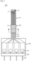
FIG. 2 is a diagram of a flexible printed circuit board for pouch cell internal pressure measurement, according to an embodiment of the present disclosure. -
FIG. 3 is a diagram of an example in which the flexible printed circuit board according to an embodiment of the present disclosure is provided in a pouch cell. -
FIG. 4 is a schematic diagram of the inside of a pouch cell in which a pressure sensor of the flexible printed circuit board ofFIG. 3 is located. -
FIG. 5 is a schematic diagram of a pressure sensor ofFIG. 4 . -
FIG. 6 is a schematic cross-sectional view taken along line A-A' ofFIG. 2 . -
FIG. 7 is a schematic diagram of a sealing portion of a pouch outer casing in which a protective sheath of the flexible printed circuit board according to an embodiment of the present disclosure has been interposed. -
FIG. 8 is a reference diagram for explaining a method of measuring the internal pressure of a pouch cell, according to another embodiment of the present disclosure. -
FIG. 9 is a reference diagram for explaining a method of measuring the internal pressure of a pouch cell by using a flexible printed circuit according to another embodiment of the present disclosure. - Embodiments of the present disclosure will now be described in detail with reference to the accompanying drawings. Terms or words used in the present specification and claims should not be interpreted as being limited to typical or dictionary meanings, but should be interpreted as having meanings and concepts, which comply with the technical aspects of the present invention, based on the principle that an inventor can appropriately define the concept of the term to describe his/her own invention in the best manner.
- Therefore, configurations illustrated in the embodiments and the drawings described in the present specification are only preferred embodiment of the present disclosure and do not represent all of the technical aspects of the present disclosure, and thus it is to be understood that various equivalents and modified examples, which may replace the configurations, are possible when filing the present application.
-
FIG. 2 is a diagram of a flexible printed circuit board for pouch cell internal pressure measurement according to an embodiment of the present disclosure,FIG. 3 is a diagram of an example in which the flexible printed circuit board according to an embodiment of the present disclosure is installed in a pouch cell, andFIG. 4 is a schematic diagram of the inside of the pouch cell in which a pressure sensor of the flexible printed circuit board ofFIG. 3 is located. - In the flexible printed
circuit board 100 according to an embodiment of the present disclosure, insulation and coating may be achieved in a way of disposing a copper clad laminate on abase film 102a, laminating a dry film on a resultant structure, and performing exposure, development, and etching to formconductor lines 101 having a predetermined interval therebetween, and then bonding acoverlay film 102b to theconductor lines 101. - The
conductor lines 101 may be formed of a metal having excellent electrical conductivity, such as copper (Cu) or silver (Ag), and aninsulating film 102 may be formed of an insulating material such as polyethylene terephthalate or polyamide and may include thebase film 102a and thecoverlay film 102b. - Because the flexible printed
circuit board 100 is capable of processing a large number of signals and loads with a minimum volume, has insulation properties and flexibility, and is very thin, apressure sensor 111 may be mounted on one end of the flexible printedcircuit board 100 and put into apouch cell 200, and may be used to measure the internal pressure of thepouch cell 200. - Referring to
FIG. 2 , the flexible printedcircuit board 100 for measuring the internal pressure of thepouch cell 200, according to an embodiment of the present disclosure, includes asensing part 110, anextension part 120, and aboard part 130. - Referring to
FIGS. 3 and4 , thesensing part 110 is a portion that enters thepouch cell 200, which is an internal pressure measurement target, and is manufactured to have a width and a length enabling disposition in agas pocket portion 230 formed in thepouch cell 200. In particular, thesensing part 110 is manufactured to have a width equal to or smaller than a width of thegas pocket portion 230. Thepressure sensor 111 may be mounted on an end portion of thesensing part 110. In addition to thepressure sensor 111, atemperature sensor 112 or a gas sensor (not shown) may be mounted on thesensing part 110 to simultaneously collect data such as a temperature and gas as well as the internal pressure of thepouch cell 200. - The
entire sensing part 110 may be parylene coated. The parylene coating refers to a polymer coating deposited on a subject in a nanometer (nm) or micrometer (um) thickness unit regardless of shape in a gaseous form in a vacuum at room temperature. When such a parylene coating is applied, a thin and transparent polymer film is formed on the entire surface of thesensing part 110. In this case, even when thesensing part 110 is placed inside thepouch cell 200, corrosion of or damage to thesensing part 110 due to an electrolyte may be prevented. - In addition, underfill or conformal coating may be additionally applied to a soldering portion of the sensing part where the pressure sensor and the conductor lines are connected to each other, to thereby reinforce a tolerance of the place where the pressure sensor is mounted to physical and chemical shocks.
- The underfill refers to a method of filling the underside of a package such as a chip with an insulating resin, and the conformal coating is a work of keeping the lifespan of components and circuit devices longer from external environments and physical influences by forming a very thin film on a printed circuit board (PCB) or various electrical boards by using a coating material.
- A waterproof micro electro-mechanical system (MEMS)
pressure sensor 111 may be employed as thepressure sensor 111. - As shown in
FIG. 5 , the waterproofMEMS pressure sensor 111 may have a structure in which asensor chip 111c is located inside acylindrical lid 111a filled with aviscous gel 111b and a PCB 111d connected to thesensor chip 111c covers a lower end portion of thecylindrical lid 111a. Compared to general MEMS pressure sensors that directly contact an external fluid (non-corrosive gas) to measure pressure, the waterproofMEMS pressure sensor 111 applied to the present embodiment may directly measure the pressures of liquid and various types of gases because theviscous gel 111b is filled in thecylindrical lid 111a, and may withstand an electrolyte and have excellent waterproof performance. - The
extension part 120 is a portion extending from thesensing part 110 to theboard part 130, and a portion of theextension part 120 may be heat-welded to a sealingportion 240 of thepouch cell 200. - A pouch
outer casing 220 may include anupper pouch sheet 221 and alower pouch sheet 222 each including an external insulation layer, a metal layer, and an internal adhesion layer, and covering upper and lower sides of anelectrode assembly 210, respectively. When the pouchouter casing 220 is sealed, respective edges of theupper pouch sheet 221 and thelower pouch sheet 222 are typically heat-welded to each other. In this case, an edge portion of theupper pouch sheet 221 and thelower pouch sheet 222 resulting from the heat welding is referred to as the sealingportion 240 or a terrace. - The
electrode assembly 210 is an assembly of electrode plates and a separator, and may be configured such that one or more positive electrode plates and one or more negative electrode plates are disposed with a separator interposed therebetween. An electrode tab may be included in each electrode plate of theelectrode assembly 210 and may be connected to an electrode lead. In thepouch cell 200, apositive electrode lead 201 and anegative electrode lead 202 may be interposed between theupper pouch sheet 221 and thelower pouch sheet 222, and respective one ends of thepositive electrode lead 201 and thenegative electrode lead 202 may be exposed and thus may function as electrode terminals. - In order to insert the
sensing part 110 of the flexible printedcircuit board 100 into thepouch cell 200 and prevent leakage of the internal pressure of thepouch cell 200, a portion of theextension part 120 is interposed between theupper pouch sheet 221 and thelower pouch sheet 222, and, in this state, the pouchouter casing 220 is sealed. - In this case, in order to prevent damage due to applied heat and pressure and strengthen adhesion with the internal adhesive layers of the pouch
outer casing 220, theextension part 120 of the flexible printedcircuit board 100 according to the present disclosure includes aprotective sheath 121 in a predetermined section. The predetermined section refers to a section of theextension part 120 that is to be interposed in the sealingportion 240 of thepouch cell 200. - As shown in
FIG. 4 , theprotective layer 121 may extend with a length equal to or longer than a width of the sealingportion 240 formed in thepouch cell 200. - Referring to
FIG. 6 , theprotective sheath 121 may be formed of a metal such as gold (Au) or copper (Cu), and may be provided in the form of enclosing the outer surface of the insulatingfilm 102 of the predetermined section. In general, although the insulatingfilm 102 made of polyimide has excellent heat resistance, the insulatingfilm 102 may be easily cut or cracks may easily occur in theconductor lines 101 due to simultaneous application of heat and pressure when the pouchouter casing 220 is heat-welded. However, in the present disclosure, theprotective sheath 121 formed of a metal-based material surrounds the insulatingfilm 102 to thereby protect the insulatingfilm 102 and theconductor lines 101 from heat and pressure during thermal welding. In addition, theprotective sheath 121 formed of a metal-based material and the inner adhesive layers of pouch sheets may strongly adhere each other, leading to an improvement in the sealing property of the corresponding portion. - Referring back to
FIGS. 2 through 4 , theboard part 130 is a portion disposed outside thepouch cell 200 and includes connector pins 132 connectable to an external device. The connector pins 132 may be connected to theconductor lines 101, respectively, by soldering 131. Theboard part 130 may be formed to have a larger width than thesensing part 110 or theextension part 120, and theconductor lines 101 may be expanded to have large widths in theboard part 130. Eachconnector pin 132 may be soldered (indicated by reference numeral 131) to each of the expanded conductor lines 101. - A
support 133 having a rod shape may be provided at an end of theboard part 130, and the connector pins 132 may each extend straight through thesupport 133, maintain a certain distance from each other, and be connected to an arm connector of an external device. - A method of measuring the internal pressure of the
pouch cell 200 by using the flexible printedcircuit board 100 for thepouch cell 200's inner pressure measurement having the above-described structure, according to the present disclosure, will now be described. - The method of measuring the internal pressure of the
pouch cell 200 includes a pressure sensor installation step and an internal pressure measurement step. - As shown in
FIG. 4 , inside thepouch cell 200, thegas pocket portion 230 is present between an area where theelectrode assembly 210 is located and the sealingportion 240 where the pouchouter casing 220 is heat-welded. Thesensing part 110 of the flexible printedcircuit board 100 is disposed in thegas pocket portion 230. - For example, when the
electrode assembly 210 is disposed in the pouchouter casing 220 during the manufacture of thepouch cell 200, thesensing part 110 may be disposed in a place corresponding to thegas pocket portion 230, and an electrolyte injection/wetting process and a process of sealing the pouchouter casing 220 may be performed, and thus thepouch cell 200 to which the flexible printedcircuit board 100 has been attached may be manufactured. - Alternatively, after the
pouch cell 200 is manufactured, the flexible printedcircuit board 100 may be inserted into thepouch cell 200. In this case, apouch cell 200 having a unsealed section is manufactured so that thesensing part 110 may be easily inserted into thepouch cell 200. The unsealed section refers to a section left without being sealed such that thesensing unit 110 may be inserted, when the pouchouter casing 220 is sealed by heat-welding the respective edges of theupper pouch sheet 221 and thelower pouch sheet 222. After thesensing part 110 of the flexible printedcircuit board 100 is pushed into thepouch cell 200 through the unsealed section, the pouchouter casing 220 is sealed by heat-welding the unsealed section. At this time, theprotective sheath 121 of theextension part 120 is heat-welded between theupper pouch sheet 221 and thelower pouch sheet 222. - In particular, the unsealed section is heat-welded using a heat-pressing
jig 30 having agroove 31 corresponding to the shape of theprotective sheath 121 of theextension part 120. A portion of the pouchouter casing 220 in which theprotective sheath 121 of theextension part 120 is interposed may have a low bonding strength compared to other sealing areas of the pouchouter casing 220 due to the thickness of theextension part 120 including theprotective sheath 121. This may be due to a lifting phenomenon caused by the inability to properly apply heat and pressure to both corners of theprotective sheath 121 and to between theupper pouch sheet 221 and thelower pouch sheet 222. - In the present embodiment, to prevent the lifting phenomenon, as shown in
FIG. 7 , theupper pouch sheet 221 is pressed from the top by using the heat-pressingjig 30 including thegroove 31, and at the same time thelower pouch sheet 222 is pressed from the bottom by using a flat heat-pressing jig (not shown), to thereby integrally heat-welding theupper pouch sheet 221, theprotective sheath 121 of theextension part 120, and thelower pouch sheet 222. In this case, upper, lower, left, and right sides of theprotective sheath 121 are closely adhered to theupper pouch sheet 221 and thelower pouch sheet 222, and thus the sealing properties of the pouchouter casing 220 and the fixing properties of the flexible printedcircuit board 100 may be improved - As described above, when the
pouch cell 200 in which the flexible printedcircuit board 100 has been installed is prepared, the internal pressure of thepouch cell 200 is measured while repeating charging and discharging of thepouch cell 200. Thepouch cell 200 may be charged/discharged by using, for example, a charging/discharging jig as shown inFIG. 8 . - The charging/discharging jig may include
voltage grippers base plate 44, and apressurization plate 45. Thepouch cell 200 is placed on thebase plate 44 of a surface plate, and thepressurization plate 45 is disposed on thepouch cell 200. In order to provide a certain pressure to thepouch cell 200 during charging and discharging, thebase plate 44 and thepressurization plate 45 may be provided with bolts and nuts at their corners and configured to be able to adjust a vertical spacing. - The
positive electrode lead 201 and thenegative electrode lead 202 of thepouch cell 200 may be respectively engaged with thevoltage grippers voltage grippers - The
board part 130 of the flexible printedcircuit board 100 may be connected to acontrol device 50 through a cable connector C1, and thecontrol device 50 may be connected to a display device (not shown) displaying a value from thepressure sensor 111 through another cable C2. - According to such a configuration, a change in the internal pressure of the
pouch cell 200 is monitored while charging and discharging of thepouch cell 200 is being repeated. When gas is generated inside thepouch cell 200 during charging and discharging, the gas is collected in thegas pocket portion 230 and the pressure of the gas is measured by thepressure sensor 111. The value of the measured gas pressure may be displayed on the display device in real time. Also, a change in the temperature inside thepouch cell 200 may be monitored by thetemperature sensor 112, along with the change in the internal pressure of thepouch cell 200. - As such, when the flexible printed
circuit board 100 for measuring the internal pressure of thepouch cell 200 is inserted into thegas pocket portion 230 of thepouch cell 200 and thepouch cell 200 is sealed, even when thepressure sensor 111 is inserted into thepouch cell 200, thepressure sensor 111 may directly measure the internal pressure of thepouch cell 200 without functional problems. -
FIG. 9 is a reference diagram for explaining a method of measuring the internal pressure of a pouch cell by using a flexible printed circuit according to another embodiment of the present disclosure. - A flexible printed
circuit board 100 for measuring the internal pressure of apouch cell 200, according to another embodiment of the present disclosure, and a method of measuring the internal pressure of thepouch cell 200 by using the flexible printedcircuit board 100 will be described with reference toFIG. 9 . - Reference numerals of
FIG. 9 that are the same as those in the above-described embodiment denote the same members, and repeated descriptions of the same members will be omitted. Differences from the above-described embodiments will be mainly described. - The flexible printed
circuit board 100 for measuring the internal pressure of thepouch cell 200, according to the present embodiment, may include two sensingparts 110 and oneboard part 130. Theextension part 120 may be configured to extend from eachsensing part 110 and be merged with eachsensing part 110 in theboard part 130. Onepressure sensor 111 may be mounted on each of the two sensingparts 110, and theboard part 130 may include a plurality of connector pins 132 necessary for signal transmission from the two sensingparts 110. - When the flexible printed
circuit board 100 for measuring the internal pressure of thepouch cell 200 is used, onesensing part 110 may be disposed in agas pocket portion 230 on a side of thepouch cell 200 where thepositive electrode lead 201 is located, and anothersensing part 110 may be disposed in agas pocket portion 230 on a side of thepouch cell 200 where thenegative electrode lead 202 is located. In this case, a pressure distribution of each region within thepouch cell 200 may be measured. - According to the present embodiment, the flexible printed
circuit board 100 for measuring the internal pressure of thepouch cell 200 may be manufactured to have two or three sensingparts 110 or more than three sensingparts 110, and thepressure sensor 111 may be disposed at several places within thepouch cell 200. - The present disclosure has been described in detail. However, it should be understood that the detailed description and specific examples, while indicating preferred embodiments of the present disclosure, are given by way of illustration only, since various changes and modifications within the scope of the present disclosure will become apparent to those skilled in the art from this detailed description.
- Meanwhile, when terms indicating directions such as up, down, left, right, front, and rear are used in the present specification, these terms indicate relative locations and are only for convenience of description, and it is apparent to those skilled in the art that these terms may vary depending on a position of a target object or a position of an observer.
Claims (12)
- A flexible printed circuit board for pouch cell internal pressure measurement comprising a plurality of conductor lines and an insulating film having insulation properties and flexibility and surrounding the plurality of conductor lines, the flexible printed circuit board comprising:a sensing part on which a pressure sensor is mounted;a board part having connector pins connected to the plurality of conductor lines, respectively; andan extension part extending from the sensing part to the board part,wherein the extension part comprises a protective sheath of a metal material that surrounds an outer surface of the insulating film in a predetermined section.
- The flexible printed circuit board of claim 1, wherein the protective sheath is a gold or copper.
- The flexible printed circuit board of claim 1, wherein the sensing part has a width equal to or smaller than a width of a gas pocket portion formed in a pouch cell that is an internal pressure measurement target, and
the protective sheath is formed to extend with a length equal to or greater than a width of a sealing portion formed in the pouch cell. - The flexible printed circuit board of claim 1, wherein the sensing part is parylene coated.
- The flexible printed circuit board of claim 4, wherein an underfill or a conformal coating is added to a portion of the sensing part where the pressure sensor and the plurality of conductor lines are soldered.
- The flexible printed circuit board of claim 1, wherein the pressure sensor is a waterproof micro electro-mechanical system (MEMS) pressure sensor.
- The flexible printed circuit board of claim 1, wherein the sensing part further comprises a temperature sensor.
- The flexible printed circuit board of claim 1, wherein the sensing part is provided in plurality and the board part is provided in one.
- A method of measuring the internal pressure of a pouch cell by using the flexible printed circuit board for pouch cell internal pressure measurement of claim 1, the pouch cell comprising a pouch outer casing including an upper pouch sheet and a lower pouch sheet covering the upper and lower sides of an electrode assembly, respectively, the method comprising:a pressure sensor installation step of sealing the pouch outer casing by thermally welding the protective sheath together with the upper pouch sheet and the lower pouch sheet when the sensing part is disposed in a gas pocket portion inside the pouch cell; andan internal pressure measurement step of connecting a data analysis device to a board part and measuring the internal pressure of the pouch cell while repeating charging and discharging of the pouch cell.
- The method of claim 9, wherein, in the pressure sensor installation step, before disposing the sensing part in the gas pocket portion, the pouch cell is partially sealed by heat-sealing the edges of the upper pouch sheet and the lower pouch sheet to have an unsealed section left so that the sensing part can be inserted, and, after the sensing part is inserted into the pouch outer casing through the unsealed section, the pouch outer casing is sealed by heat-welding the unsealed section.
- The method of claim 10, wherein the upper pouch sheet, the protective sheath, and the lower pouch sheet are integrally heat-welded with one another by using a heat-pressing jig having a groove corresponding to the shape of the protective sheath of the extension part when heat-welding the unsealed section.
- The method of claim 9, wherein, by using a flexible printed circuit board comprising the two sensing parts and the one board part, in the pressure sensor installation step, one of the two sensing parts is disposed in the gas pocket portion on a side of the pouch cell where the positive electrode lead is located, and the other sensing part is disposed in the gas pocket portion on a side of the pouch cell where the negative electrode lead is located.
Applications Claiming Priority (2)
| Application Number | Priority Date | Filing Date | Title |
|---|---|---|---|
| KR1020200184945A KR102826522B1 (en) | 2020-12-28 | 2020-12-28 | A flexible printed circuit board for measuring the internal pressure of a pouch cell and a method for measuring the internal pressure of a pouch cell by using the same |
| PCT/KR2021/019009 WO2022145816A1 (en) | 2020-12-28 | 2021-12-14 | Flexible printed circuit board for measuring internal pressure of pouch cell and method for measuring internal pressure of pouch cell |
Publications (2)
| Publication Number | Publication Date |
|---|---|
| EP4181271A1 true EP4181271A1 (en) | 2023-05-17 |
| EP4181271A4 EP4181271A4 (en) | 2024-10-23 |
Family
ID=82260652
Family Applications (1)
| Application Number | Title | Priority Date | Filing Date |
|---|---|---|---|
| EP21915614.8A Pending EP4181271A4 (en) | 2020-12-28 | 2021-12-14 | FLEXIBLE CIRCUIT BOARD FOR MEASURING THE INTERNAL PRESSURE OF A BAG CELL AND METHOD FOR MEASURING THE INTERNAL PRESSURE OF A BAG CELL |
Country Status (6)
| Country | Link |
|---|---|
| US (1) | US12537235B2 (en) |
| EP (1) | EP4181271A4 (en) |
| JP (1) | JP7428331B2 (en) |
| KR (1) | KR102826522B1 (en) |
| CN (1) | CN115917832B (en) |
| WO (1) | WO2022145816A1 (en) |
Cited By (1)
| Publication number | Priority date | Publication date | Assignee | Title |
|---|---|---|---|---|
| EP4009417A4 (en) * | 2020-05-20 | 2024-06-12 | Lg Energy Solution, Ltd. | POUCH SECONDARY BATTERY WITH PRESSURE GAUGE DEVICE FOR MEASURING THE INTERNAL PRESSURE |
Families Citing this family (3)
| Publication number | Priority date | Publication date | Assignee | Title |
|---|---|---|---|---|
| KR20230142248A (en) * | 2022-04-01 | 2023-10-11 | 주식회사 엘지에너지솔루션 | Pouch-type Battery Cell Comprising FPCB |
| CN117954717A (en) * | 2022-10-21 | 2024-04-30 | 宁德时代新能源科技股份有限公司 | Battery pack, electric device, battery pack detection method and computer storage medium |
| CN121002699A (en) * | 2023-03-30 | 2025-11-21 | 株式会社 Lg新能源 | Battery cells capable of detecting electrolyte leaks |
Family Cites Families (22)
| Publication number | Priority date | Publication date | Assignee | Title |
|---|---|---|---|---|
| JP4518591B2 (en) | 1999-05-31 | 2010-08-04 | 三洋電機株式会社 | Battery pack with built-in thin battery |
| JP2002313431A (en) * | 2001-04-11 | 2002-10-25 | Mitsubishi Materials Corp | Non-aqueous electrolyte secondary battery |
| KR100889244B1 (en) | 2005-04-20 | 2009-03-17 | 주식회사 엘지화학 | Secondary Battery Module with Piezoelectric Sensor |
| KR100834337B1 (en) * | 2006-09-29 | 2008-06-02 | 주식회사 케이이씨 | Pressure sensor device and manufacturing method thereof |
| JP2010244844A (en) | 2009-04-06 | 2010-10-28 | Nec Energy Devices Ltd | Battery pack |
| US9136509B2 (en) * | 2011-05-27 | 2015-09-15 | Apple Inc. | Battery cell with an integrated pouch metal foil terminal |
| CN102496750B (en) | 2011-12-20 | 2014-10-08 | 华为技术有限公司 | Battery |
| DE102012207999A1 (en) * | 2012-05-14 | 2013-11-14 | Robert Bosch Gmbh | Sheath foil for a galvanic cell, electrochemical storage, electrochemical storage system, flexible foil for a sheath of a galvanic cell and method for determining a state quantity of an electrochemical storage |
| US9631997B2 (en) * | 2013-05-14 | 2017-04-25 | Infineon Technologies Ag | Apparatus for measuring a pressure, a method for manufacturing an apparatus for measuring a pressure and a battery |
| KR101595498B1 (en) * | 2014-04-17 | 2016-02-18 | 주식회사 아이티엠반도체 | Polymer battery cell and electronic device including the same |
| EP3128574B1 (en) * | 2014-04-30 | 2018-08-22 | LG Chem, Ltd. | Battery pack comprising a pouch-type cell secondary battery and said secondary battery comprising a circuit board |
| WO2015173686A1 (en) * | 2014-05-16 | 2015-11-19 | Semiconductor Energy Laboratory Co., Ltd. | Electronic device with secondary battery |
| DE102014222896A1 (en) | 2014-11-10 | 2016-05-12 | Robert Bosch Gmbh | Galvanic cell and method for producing a galvanic cell |
| US10008702B2 (en) | 2015-05-20 | 2018-06-26 | Farasis Energy, Inc. | Pouch cell |
| KR102470882B1 (en) | 2016-03-31 | 2022-11-25 | 에스케이온 주식회사 | Unit battery module and measuring for state of health thereof |
| EP3526568A1 (en) * | 2016-10-17 | 2019-08-21 | Silicon Microstructures, Inc. | Light shields for catheter sensors |
| JP2018078067A (en) | 2016-11-11 | 2018-05-17 | リチウム エナジー アンド パワー ゲゼルシャフト ミット ベシュレンクテル ハフッング ウント コンパニー コマンディトゲゼルシャフトLithium Energy and Power GmbH & Co. KG | Electric storage element, electric storage device, and internal pressure detection method |
| JP2018112433A (en) | 2017-01-10 | 2018-07-19 | セイコーエプソン株式会社 | Pressure sensor, electronic apparatus, and movable body |
| CN207559000U (en) | 2017-12-15 | 2018-06-29 | 浙江隆劲电池科技有限公司 | A kind of lithium battery of detectable internal temperature and pressure |
| KR102175734B1 (en) * | 2018-01-24 | 2020-11-06 | 주식회사 아모그린텍 | Sensor for detecting the pressure of battery and device having the same |
| KR102306042B1 (en) | 2018-12-11 | 2021-09-27 | 주식회사 엘지에너지솔루션 | FPCB assembly for battery module and a method for manufacturing FPCB assembly and a battery module including the same |
| EP3736878B1 (en) * | 2019-05-10 | 2024-04-10 | Andreas Stihl AG & Co. KG | Battery pack and processing system |
-
2020
- 2020-12-28 KR KR1020200184945A patent/KR102826522B1/en active Active
-
2021
- 2021-12-14 JP JP2022576087A patent/JP7428331B2/en active Active
- 2021-12-14 WO PCT/KR2021/019009 patent/WO2022145816A1/en not_active Ceased
- 2021-12-14 CN CN202180052564.8A patent/CN115917832B/en active Active
- 2021-12-14 US US18/017,790 patent/US12537235B2/en active Active
- 2021-12-14 EP EP21915614.8A patent/EP4181271A4/en active Pending
Cited By (1)
| Publication number | Priority date | Publication date | Assignee | Title |
|---|---|---|---|---|
| EP4009417A4 (en) * | 2020-05-20 | 2024-06-12 | Lg Energy Solution, Ltd. | POUCH SECONDARY BATTERY WITH PRESSURE GAUGE DEVICE FOR MEASURING THE INTERNAL PRESSURE |
Also Published As
| Publication number | Publication date |
|---|---|
| CN115917832B (en) | 2026-02-10 |
| US20230291017A1 (en) | 2023-09-14 |
| KR20220093841A (en) | 2022-07-05 |
| US12537235B2 (en) | 2026-01-27 |
| KR102826522B1 (en) | 2025-06-26 |
| JP2023529694A (en) | 2023-07-11 |
| WO2022145816A1 (en) | 2022-07-07 |
| EP4181271A4 (en) | 2024-10-23 |
| JP7428331B2 (en) | 2024-02-06 |
| CN115917832A (en) | 2023-04-04 |
Similar Documents
| Publication | Publication Date | Title |
|---|---|---|
| US12537235B2 (en) | Flexible printed circuit board for measuring internal pressure of pouch cell, and method of measuring internal pressure of pouch cell | |
| CN110140254B (en) | Pouch type secondary battery pack including protection circuit module | |
| KR101896922B1 (en) | Covering material for battery and lithum-ion rechargeable battery | |
| US6822420B2 (en) | Battery power source device including rechargeable battery and circuit board joined thereto | |
| KR102924944B1 (en) | Battery module comprising temperature sensor | |
| JP2021518983A (en) | Battery module with connector mounted on FPCB, battery pack including it and automobile | |
| JP5151115B2 (en) | Bipolar secondary battery | |
| EP2495794B1 (en) | Battery pack | |
| US6811902B2 (en) | Battery pack having improved battery cell terminal configuration | |
| KR20220003730A (en) | Battery module and battery pack including the same and manufacturing method of the same | |
| US12573675B2 (en) | Battery module sensing unit and manufacturing method thereof | |
| JP7581747B2 (en) | battery | |
| US20230318094A1 (en) | Battery Cell | |
| KR20130005117A (en) | Battery cell and battery pack comprising thereof | |
| JP7596018B2 (en) | Pouch-type battery cell containing flexible printed circuit board | |
| CN114204127B (en) | An insulation protection assembly method for polymer lithium-ion batteries | |
| CN104364940A (en) | Protective device for an electronic component, electric circuit, electrochemical energy store, method for producing an electric circuit and use of a flexible sheath | |
| KR102884176B1 (en) | Pouch type secondary battery having the Pressure Measuring Device for measuring the internal pressure | |
| CN224006074U (en) | Busbar assembly and battery module including busbar assembly | |
| KR20260054411A (en) | Management module and battery module including thereof | |
| JP2014102989A (en) | Battery pack |
Legal Events
| Date | Code | Title | Description |
|---|---|---|---|
| STAA | Information on the status of an ep patent application or granted ep patent |
Free format text: STATUS: THE INTERNATIONAL PUBLICATION HAS BEEN MADE |
|
| PUAI | Public reference made under article 153(3) epc to a published international application that has entered the european phase |
Free format text: ORIGINAL CODE: 0009012 |
|
| STAA | Information on the status of an ep patent application or granted ep patent |
Free format text: STATUS: REQUEST FOR EXAMINATION WAS MADE |
|
| 17P | Request for examination filed |
Effective date: 20230207 |
|
| AK | Designated contracting states |
Kind code of ref document: A1 Designated state(s): AL AT BE BG CH CY CZ DE DK EE ES FI FR GB GR HR HU IE IS IT LI LT LU LV MC MK MT NL NO PL PT RO RS SE SI SK SM TR |
|
| DAV | Request for validation of the european patent (deleted) | ||
| DAX | Request for extension of the european patent (deleted) | ||
| A4 | Supplementary search report drawn up and despatched |
Effective date: 20240919 |
|
| RIC1 | Information provided on ipc code assigned before grant |
Ipc: H01M 50/284 20210101ALI20240913BHEP Ipc: H05K 1/11 20060101ALI20240913BHEP Ipc: H05K 3/34 20060101ALI20240913BHEP Ipc: H05K 1/18 20060101ALI20240913BHEP Ipc: H01M 10/42 20060101ALI20240913BHEP Ipc: H01M 10/48 20060101AFI20240913BHEP |