EP4180909B1 - Klappbares scharnier und elektronische vorrichtung - Google Patents
Klappbares scharnier und elektronische vorrichtung Download PDFInfo
- Publication number
- EP4180909B1 EP4180909B1 EP22172888.4A EP22172888A EP4180909B1 EP 4180909 B1 EP4180909 B1 EP 4180909B1 EP 22172888 A EP22172888 A EP 22172888A EP 4180909 B1 EP4180909 B1 EP 4180909B1
- Authority
- EP
- European Patent Office
- Prior art keywords
- base
- coupled
- support plate
- foldable hinge
- arm
- Prior art date
- Legal status (The legal status is an assumption and is not a legal conclusion. Google has not performed a legal analysis and makes no representation as to the accuracy of the status listed.)
- Active
Links
Images


Classifications
-
- F—MECHANICAL ENGINEERING; LIGHTING; HEATING; WEAPONS; BLASTING
- F16—ENGINEERING ELEMENTS AND UNITS; GENERAL MEASURES FOR PRODUCING AND MAINTAINING EFFECTIVE FUNCTIONING OF MACHINES OR INSTALLATIONS; THERMAL INSULATION IN GENERAL
- F16C—SHAFTS; FLEXIBLE SHAFTS; ELEMENTS OR CRANKSHAFT MECHANISMS; ROTARY BODIES OTHER THAN GEARING ELEMENTS; BEARINGS
- F16C11/00—Pivots; Pivotal connections
- F16C11/04—Pivotal connections
-
- G—PHYSICS
- G06—COMPUTING OR CALCULATING; COUNTING
- G06F—ELECTRIC DIGITAL DATA PROCESSING
- G06F1/00—Details not covered by groups G06F3/00 - G06F13/00 and G06F21/00
- G06F1/16—Constructional details or arrangements
- G06F1/1613—Constructional details or arrangements for portable computers
- G06F1/1633—Constructional details or arrangements of portable computers not specific to the type of enclosures covered by groups G06F1/1615 - G06F1/1626
- G06F1/1675—Miscellaneous details related to the relative movement between the different enclosures or enclosure parts
- G06F1/1681—Details related solely to hinges
-
- E—FIXED CONSTRUCTIONS
- E05—LOCKS; KEYS; WINDOW OR DOOR FITTINGS; SAFES
- E05D—HINGES OR SUSPENSION DEVICES FOR DOORS, WINDOWS OR WINGS
- E05D11/00—Additional features or accessories of hinges
- E05D11/08—Friction devices between relatively-movable hinge parts
- E05D11/082—Friction devices between relatively-movable hinge parts with substantially radial friction, e.g. cylindrical friction surfaces
-
- E—FIXED CONSTRUCTIONS
- E05—LOCKS; KEYS; WINDOW OR DOOR FITTINGS; SAFES
- E05D—HINGES OR SUSPENSION DEVICES FOR DOORS, WINDOWS OR WINGS
- E05D3/00—Hinges with pins
- E05D3/06—Hinges with pins with two or more pins
- E05D3/12—Hinges with pins with two or more pins with two parallel pins and one arm
- E05D3/122—Gear hinges
-
- E—FIXED CONSTRUCTIONS
- E05—LOCKS; KEYS; WINDOW OR DOOR FITTINGS; SAFES
- E05D—HINGES OR SUSPENSION DEVICES FOR DOORS, WINDOWS OR WINGS
- E05D3/00—Hinges with pins
- E05D3/06—Hinges with pins with two or more pins
- E05D3/18—Hinges with pins with two or more pins with sliding pins or guides
-
- G—PHYSICS
- G06—COMPUTING OR CALCULATING; COUNTING
- G06F—ELECTRIC DIGITAL DATA PROCESSING
- G06F1/00—Details not covered by groups G06F3/00 - G06F13/00 and G06F21/00
- G06F1/16—Constructional details or arrangements
- G06F1/1613—Constructional details or arrangements for portable computers
- G06F1/1633—Constructional details or arrangements of portable computers not specific to the type of enclosures covered by groups G06F1/1615 - G06F1/1626
- G06F1/1637—Details related to the display arrangement, including those related to the mounting of the display in the housing
- G06F1/1652—Details related to the display arrangement, including those related to the mounting of the display in the housing the display being flexible, e.g. mimicking a sheet of paper, or rollable
-
- G—PHYSICS
- G09—EDUCATION; CRYPTOGRAPHY; DISPLAY; ADVERTISING; SEALS
- G09F—DISPLAYING; ADVERTISING; SIGNS; LABELS OR NAME-PLATES; SEALS
- G09F9/00—Indicating arrangements for variable information in which the information is built-up on a support by selection or combination of individual elements
- G09F9/30—Indicating arrangements for variable information in which the information is built-up on a support by selection or combination of individual elements in which the desired character or characters are formed by combining individual elements
- G09F9/301—Indicating arrangements for variable information in which the information is built-up on a support by selection or combination of individual elements in which the desired character or characters are formed by combining individual elements flexible foldable or roll-able electronic displays, e.g. thin LCD, OLED
-
- E—FIXED CONSTRUCTIONS
- E05—LOCKS; KEYS; WINDOW OR DOOR FITTINGS; SAFES
- E05Y—INDEXING SCHEME ASSOCIATED WITH SUBCLASSES E05D AND E05F, RELATING TO CONSTRUCTION ELEMENTS, ELECTRIC CONTROL, POWER SUPPLY, POWER SIGNAL OR TRANSMISSION, USER INTERFACES, MOUNTING OR COUPLING, DETAILS, ACCESSORIES, AUXILIARY OPERATIONS NOT OTHERWISE PROVIDED FOR, APPLICATION THEREOF
- E05Y2999/00—Subject-matter not otherwise provided for in this subclass
Definitions
- the present invention relates to the field of electronic equipment and, more particularly, to a foldable hinge and an electronic device.
- foldable screens are widely used in the technical field of electronic equipment, and the technology for drop-shaped foldable screens is relatively mature at present. Foldable hinges of such foldable screens can help achieve the folding function while avoiding damage to the screen because the folding angle is too big.
- the foldable hinges In order to configure the foldable screens to be drop-shaped, the foldable hinges usually have many elements, resulting in a complex structure of the foldable hinges.
- US 2021/181808 A1 discloses a hinge and a mobile terminal to resolve poor use effect of a foldable electronic device.
- the hinge includes a main body, and a first folding assembly and a second folding assembly that are symmetrically disposed along the main body.
- a length of the hinge can be extended, and an accommodation space for accommodating the flexible display can be formed.
- the first folding assembly and the second folding assembly are rotated away from each other, the length of the hinge can be reduced, and a support surface for supporting the flexible display can be formed, so that the flexible display cannot be stretched, compressed, or the like during folding and unfolding.
- WO 2021/115462 A1 relates to the technical field of electronic devices.
- the rotary shaft mechanism comprises a main shaft assembly and two folding assemblies, which are symmetrically arranged relative to the main shaft assembly; and the two folding assemblies can rotate in a direction facing each other or in a direction away from each other relative to the main shaft assembly.
- each of the folding assemblies comprises a rotary assembly, a supporting plate and a shell-fixing frame, wherein the rotary assembly is rotationally connected to the main shaft assembly, and the supporting plate is rotationally connected to the shell-fixing frame and is slidably connected to the rotary assembly.
- the rotary shaft mechanism By using the rotary shaft mechanism, in the relative rotation process of two shell-fixing frames, two supporting plates rotate in the same direction relative to the shell-fixing frames on corresponding sides, so that the two supporting plates and the main shaft assembly can form a screen-accommodating space similar to a triangle shape, and when the electronic device is in a closed state, the screen-accommodating space can be used for accommodating a bent portion of a flexible screen.
- WO 2021/129882 A1 discloses a foldable electronic device that has an open state and a closed state.
- the electronic device comprises a housing apparatus and a screen;
- the housing apparatus comprises a first housing, a second housing, and a hinge assembly, the hinge assembly is connected between the first housing and the second housing, the first housing and the second housing can be unfolded or folded relative to each other by using the hinge assembly, to enable the housing apparatus to be unfolded or folded, and the hinge assembly comprises a shaft, a first support plate, and a second support plate;
- the screen comprises a first non-bendable part, a first bendable part, a second non-bendable part, a second bendable part, a third non-bendable part, a third bendable part, and a fourth non-bendable part that are sequentially arranged, the first non-bendable part is fastened to the first housing, the fourth non-bendable part is fastened to the second housing, the first bendable part is disposed corresponding to
- WO 2021/173116 A1 discloses a foldable display screen for a device.
- the foldable display screen includes a first portion, a second portion, and an intermediary portion between the first portion and the second portion.
- the device further includes a hinge joint coupled to the first portion and the second portion to fold the first portion and the second about the intermediary portion.
- the device includes an actuating block abutting the intermediary portion and the hinge joint. The actuating block, in response to receiving a pressing force from a user on the intermediary portion above the actuating block, is to cause the hinge joint to operate and fold the foldable display screen.
- the present invention provides a foldable hinge and an electronic device.
- the foldable hinge can provide sufficient drop-shaped receiving space for a flexible screen when a mobile terminal is in a folded state.
- Embodiments of the present invention propose a foldable hinge as defined in current claim 1.
- the first body portion has a second circular arc groove an axis m of the second circular arc groove being parallel to an axis m of the first arc arm; and the support member includes a first support plate and a second arc arm, an end of the second arc arm is coupled to the first support plate, and the second arc arm is in the second circular arc groove and is slidable along the second circular arc groove.
- connection block and the second arc arm are on a common surface of the first support plate, and the connection block is coupled to the first support plate; and a half-moon-shaped side wall of the connection block has the first guiding sliding slot.
- the first guiding sliding slot exhibits a circular arc shape.
- connection block protrudes relative to a side edge of the first support plate close to the base, and the portion of the connection block has a support surface;
- the foldable hinge further includes a second support plate between the two folding assemblies, and the second support plate is movably coupled to the base and is movable relative to the base in a direction towards or away from the base;
- the portion of the connection block is on a side of the second support plate close to the base, and the support surface is in contact with a surface of the second support plate close to the base in response to unfolding the two folding assemblies; and the support surface is separated from the second support plate in response to bringing the two folding assemblies together.
- a surface of the base close to the second support plate has a first mounting slot, and a side wall of the first mounting slot has a limiting recess;
- the foldable hinge further includes an elastic member and a connection bracket;
- the connection bracket includes a second body portion and a limiting portion, the second body portion being in the first mounting slot and the limiting portion being in the limiting recess;
- the elastic member is in the limiting recess, and the elastic member is between the limiting portion and a side wall of the limiting recess; and the second body portion is coupled to the second support plate.
- the foldable hinge further includes a guide member; the first mounting slot has a guide hole in a bottom of the first mounting slot; and the guide member has a first end coupled to the connection bracket and a second end inserted in the guide hole.
- the foldable hinge further includes a synchronization assembly, the synchronization assembly is in the base, and the synchronization assembly is coupled to the two folding assemblies.
- the synchronization assembly includes two synchronizing swing arms extending to both sides of the base correspondingly; the two synchronizing swing arms are transmissively coupled; and each synchronizing swing arm has a first end rotatably coupled to the base and a second end slidingly coupled to the first body portion.
- the first body portion has a second recess on a side wall of the first body portion close to the base, and a side wall of the second recess has a second guiding sliding slot; and the second end of the synchronizing swing arm away from the base has a connection shaft, and the connection shaft is in the second guiding sliding slot.
- the synchronizing swing arm includes a gear portion and a third body portion, and the gear portion and the connection shaft are at two ends of the third body portion correspondingly; and the gear portions of the two synchronizing swing arms are transmissively coupled in an engaging manner.
- the foldable hinge further includes a mounting shaft in the base, and the mounting shaft is coaxially inserted in the gear portion and circumferentially limited by the gear portion; and the foldable hinge further includes a damping ring fitted over the mounting shaft, and the damping ring is in interference fit with the mounting shaft and is fixedly coupled to the base.
- each synchronization assembly further includes a plurality of synchronizing gears engaging with each other, and the gear portions of the two synchronizing swing arms are transmissively coupled by the plurality of synchronizing gears.
- the foldable hinge further includes a mounting shaft in the base, and the mounting shaft is coaxially inserted in the synchronizing gear and circumferentially limited by the synchronizing gear; and the foldable hinge further includes a damping ring fitted over the mounting shaft, and the damping ring is in interference fit with the mounting shaft and is fixedly coupled to the base.
- embodiments of the present invention propose an electronic device, including two housings, a flexible screen, and at least one foldable hinge as described in the previous aspect.
- the two housings are coupled to rotating arms of the two folding assemblies correspondingly, and the flexible screen is coupled to the two housings.
- the support member is rotatably coupled to the second end of the rotating arm away from the base, and the side of the support member close to the base is rotatably coupled to the base, when the two folding assemblies are brought together, the rotating arms and the support members rotate relative to the base, and the support members can slide in the direction away from the base.
- the distance between the portions of the two support members coupled to the rotating arms is smaller than the distance between the portions of the two support members coupled to the base, such that the two support members and the base form a drop-shaped receiving space, and no squeezing force or stretching force is exerted on the flexible screen when the flexible screen is received in the drop-shaped receiving space, thereby preventing the flexible screen from creasing or even being damaged.
- the rotating arms and the support members rotate relative to the base, and the support members can slide in the direction towards the base, such that the two support members are restored to an unfolded state, and the flexible screen is spread out on the two support members and the base.
- Three elements - the base, the rotating arms, and the support members - can form the drop-shaped receiving space, thereby reducing the number of elements and making the structure simpler and more compact.
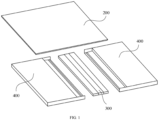
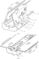
- FIG. 1 is a schematic diagram showing an electronic device in accordance with an embodiment of the present invention.
- the electronic device includes a foldable hinge 300, two middle frames 400, and a flexible screen 200.
- the two middle frames 400 are each coupled to the foldable hinge 300.
- the flexible screen 200 is coupled to the two middle frames 400.
- the two middle frames 400 may open and close relative to each other under an action of the foldable hinge 300, and the flexible screen 200 may be bent under an action of the middle frames 400.
- FIG. 2 is a schematic diagram showing a foldable hinge in accordance with an embodiment of the present invention. As shown in FIG. 2 , the foldable hinge includes a base 10 and two folding assemblies 20.
- the two folding assemblies 20 are on both sides, e.g., opposing sides, of the base 10 and coupled to the base 10, and the two folding assemblies 20 may open and close relative to each other, realizing a folding function of the foldable hinge.
- each folding assembly 20 includes a rotating arm 22 and a support member 21.
- a first end of the rotating arm 22 is rotatably coupled to the base 10, and the support member 21 is rotatably coupled to a second end of the rotating arm 22 away from the base 10.
- a side of the support member 21 close to the base 10 is rotatably coupled to the base 10, and the support member 21 is slidable in a direction approaching/towards or away from the base 10.
- the support member is rotatably coupled to the second end of the rotating arm away from the base, and the side of the support member close to the base is rotatably coupled to the base, when the two folding assemblies are brought together, the rotating arms and the support members rotate relative to the base, and the support members can slide in the direction away from the base.
- the distance between the portions of the two support members coupled to the rotating arms is smaller than the distance between the portions of the two support members coupled to the base, such that the two support members and the base form a drop-shaped receiving space, and no squeezing force or stretching force is exerted on the flexible screen when the flexible screen is received in the drop-shaped receiving space, thereby preventing the flexible screen from creasing or even being damaged.
- the rotating arms and the support members rotate relative to the base, and the support members can slide in the direction towards or approaching the base, such that the two support members are restored to an unfolded state, and the flexible screen is spread out on the two support members and the base.
- Three elements - the base, the rotating arms, and the support members - can form the drop-shaped receiving space, thereby reducing the number of elements and making the structure simpler and more compact.
- each folding assembly 20 may include one or more rotating arms 22.
- each folding assembly 20 includes two rotating arms 22 on a common side or surface of the support member 21, and the rotating arms 22 are close to the two ends of the support member 21.
- the two support members 21 rotate facing each other; the two rotating arms 22 rotate facing each other; the support members 21 rotate relative to the rotating arms 22 and relative to the base 10, and slide in the direction approaching the base 10.
- the foldable hinge is folded until the two folding assemblies 20 come together, the distance between the portions of the two support members 21 coupled to the rotating arms 22 is smaller than the distance between the portions of the two support members 21 coupled to the base 10, and the two support members 21 and the base 10 enclose the drop-shaped receiving space.
- the two support members 21 When the foldable hinge is unfolded, the two support members 21 rotate in a direction away from each other; the two rotating arms 22 rotate in a direction away from each other; the support members 21 rotate relative to the rotating arms 22 and relative to the base 10, and slide in the direction away from the base 10.
- the two support members 21 In a process of gradually unfolding the foldable hinge, as the two support members 21 rotate in the direction away from each other relative to the base 10 and the two support members 21 slide in the direction away from the base 10, the two support members 21 gradually rotate to a common surface, which can provide good support for the flexible screen.
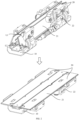
- FIG. 3 is a schematic diagram showing a part of a base in accordance with an embodiment of the present invention.
- a surface of the base 10 has a first circular arc groove 11.
- the first circular arc groove 11 is formed in a top surface of the base 10.
- the top surface of the base 10 is a surface of the base 10 close to the flexible screen in the unfolded state.
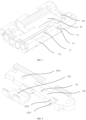
- FIG. 4 is a schematic diagram showing a rotating arm in accordance with an embodiment of the present invention.
- the rotating arm 22 of the folding assembly 20 includes a first body portion 221 and a first arc arm 222, and an end of the first arc arm 222 is coupled to the first body portion 221.
- the first body portion 221 also has a connection hole 221a.
- the rotating arm 22 can be coupled to two housings of the electronic device, such that the rotating arm 22 and the two housings are formed into one piece, which is beneficial to the installation of the flexible screen.
- FIG. 5 is a schematic diagram showing a connection between a rotating arm and a base in accordance with an embodiment of the present invention. As shown in FIG. 5 , the first arc arm 222 is in the first arc groove 11 and is slidable along the first arc groove 11.
- the rotating arm 22 can rotate around an axis of the first arc groove 11 relative to the base 10, realizing a transition of the folding assembly from a flattened or unfolded state to a closed or folded state.
- the first arc arm 222 and the first arc groove 11 cooperate with each other to form a virtual axis type connection, which can hide a connection structure of the rotating arm 22 and the base 10 inside the base 10 and make the foldable hinge more compact.
- the first circular arc groove 11 may be a quarter arc, a one-third arc, or the like
- the first arc arm 222 may be a quarter arc, a one-third arc, or the like.
- a person skilled in the art can adapt specific parameters of the first circular arc groove 11 and the first arc arm 222 to actual needs.
- each of the first circular arc groove 11 and the first arc arm 222 is a one-third arc.
- the first arc groove 11 also has an avoidance notch 111 at an opening of the first arc groove 11.
- the avoidance notch 111 is on a side wall of the base 10 close to the rotating arm 22.
- the avoidance notch 111 can avoid the rotating arm 22, so that the rotating arm 22 has more room for rotation.
- the rotating arm 22 When the folding assembly 20 is in the unfolded state, the rotating arm 22 is in the avoidance notch 111, and the first arc arm 222 is mounted in the first arc groove 11. During the folding of the folding assembly 20, the rotating arm 22 rotates to an outer side of the avoidance notch 111, and the first arc arm 222 slides along the first arc groove 11 toward an outer side of the first arc groove 11. When the folding assembly 20 is in the folded state, an end of the first arc arm 222 away from the first body portion 221 is in the first circular arc groove 11.
- the first body portion 221 of the rotating arm 22 has a second circular arc groove 2211, an axis m1 of the second circular arc groove 2211 being parallel to an axis m2 of the first arc arm 222.
- the second circular arc groove 2211 is used for connection with the support member 21.
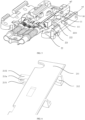
- FIG. 6 is a schematic diagram showing a part of a support member in accordance with an embodiment of the present invention.
- the support member 21 includes a first support plate 211, a second arc arm 212, and a connection block 213, and an end of the second arc arm 212 is coupled to the first support plate 211.
- connection block 213 and the second arc arm 212 are on a common side or surface of the first support plate 211, and the connection block 213 is coupled to the first support plate 211.
- a half-moon-shaped side wall of the connection block 213 has a first guiding sliding slot 2131.
- FIG. 7 is a schematic diagram showing a part of a folded hinge in a folded state in accordance with an embodiment of the present invention. As shown in FIG. 7 , the second arc arm 212 is in the second circular arc groove 2211 and is slidable along the second circular arc groove 2211.
- the second arc arm 212 is assembled in the second circular arc groove 2211 to achieve a rotational connection between the rotating arm 22 and the support member 21, so that the rotating arm 22 has a certain degree of freedom of rotation.
- the cooperation between the second arc arm 212 and the second circular arc groove 2211 constitutes a virtual axis type connection, which can hide the connection structure between the rotating arm 22 and the base 10 inside the base 10 and make the foldable hinge more compact.
- a rotation axis of the support member 21 relative to the rotating arm 22 and a rotation axis of the rotating arm 22 relative to the base 10 are parallel.
- the support member 21 and the rotating arm 22 as well as the rotating arm 22 and the base 10 can rotate smoothly, and there will be no obvious gap, improving the stability of the foldable hinge.
- the second circular arc groove 2211 may be a quarter arc, a one-third arc, or the like; and the second arc arm 212 can be a quarter arc, a one-third arc, or the like.
- a person skilled in the art can adapt specific parameters of the second arc arm 212 and the second circular arc groove 2211 to actual needs.
- each of the first circular arc groove 11 and the first arc arm 222 is a quarter arc.
- the surface of the base 10 also has a first recess 12 on a side of the first circular arc groove 11, and a side wall of the first recess 12 has a pin shaft 13.
- the connection block 213 of the support member 21 is in the first recess 12 and the pin shaft 13 is in the first guiding sliding slot 2131.
- connection block 213 By mounting the connection block 213 in the first recess 12 and mounting the pin shaft 13 in the first guiding sliding slot 2131, a rotational connection between the support member 21 and the base 10 can be realized; the support member 21 can be rotated at any angle relative to the base 10 during folding; and a connection structure of the connection block 213 and the first recess 12 can be hidden inside the base 10, making the foldable hinge more compact.
- the pin shaft 13 slides in the first guiding sliding slot 2131, enabling a sliding connection between the support member 21 and the base 10.
- connection block 213 When the folding assembly 20 is in the unfolded state, the connection block 213 is in the first recess 12 and the pin shaft 13 is at a first end of the first guiding sliding slot 2131 close to the support member 21. In the process of bringing the folding assemblies 20 together, the connection block 213 rotates with the pin shaft 13 as a center, and the pin shaft 13 slides along the first guiding sliding slot 2131 toward a second end of the first guiding sliding slot 2131 away from the support member 21. When the folding assemblies 20 are in the folded state, the pin shaft 13 is at the second end of the first guiding sliding slot 2131 away from the support member 21.
- the first guiding sliding slot 2131 exhibits a circular arc shape, and the pin shaft 13 makes a circular arc movement relative to the support member 21 during rotation of the rotating arm 22.
- a cross-sectional shape of the pin shaft 13 is circular. In other examples, the cross-sectional shape of the pin shaft 13 may also be polygonal.
- each of two opposing side walls of the first recess 12 has a pin shaft 13, and two pins 13 are arranged coaxially.
- Each of two side walls of the connection block 213 have a first guiding sliding slot 2131, and the two pins 13 slide in the two first guiding sliding slots 2131 correspondingly, which can make the sliding between the support members 21 and the base 10 more stable.
- connection block 213 protrudes relative to a side edge of the first support plate 211 close to the base 10, and the portion 213a of the connection block 213 has a support surface 2132.
- the foldable hinge also includes a second support plate 30 between the two folding assemblies 20, and the second support plate 30 is movably coupled to the base 10 and can move relative to the base 10 in a direction approaching or away from the base 10. A direction of movement of the second support plate 30 is schematically illustrated in FIG. 7 by the double-headed arrow.
- FIG. 8 is a schematic diagram showing a part of a folded hinge in an unfolded state in accordance with an embodiment of the present invention.
- the second support plate 30 is omitted in FIG. 8 .
- the portion 213a of the connection block 213 is on a side of the second support plate 30 close to the base 10, and the support surface 2132 is in contact with a surface of the second support plate 30 close to the base 10. That is, the portion 213a of the connection block 213 moves to below the second support plate 30 and the support surface 2132 contacts a lower surface of the second support plate 30, to hold the second support plate 30.
- the support surface 2132 is separated from the second support plate 30 when the two folding assemblies 20 are brought together.
- connection block 213 When the two folding assemblies 20 are unfolded, the connection block 213 is in the first recess 12 and right below the second support plate 30. A surface of the connection block 213 close to the second support plate 30 is in contact with the second support plate 30, in which case the connection block 213 can support the second support plate 30 and hold up the second support plate 30.
- the connection block 213 In the process of bringing the two folding assemblies 20 together, along with the rotation of the support member 21, the connection block 213 gradually rotates to a lateral side of the second support plate 30, in which case the connection block 213 is separated from the second support plate 30, and the second support plate 30 loses support and moves in the direction towards the base 10 to be closer to the base, thereby enlarging the drop-shaped receiving space formed when the folding assemblies 20 is in the folded state.
- FIG. 9 is a schematic diagram showing a second support plate in accordance with an embodiment of the present invention.
- the foldable hinge also includes an elastic member 41 and a connection bracket 42, and the second support plate 30 is mounted on the base 10 by the elastic member 41 and the connection bracket 42.
- FIG. 10 is a schematic diagram showing that the second support plate and the base are assembled in accordance with an embodiment of the present invention.
- a surface of the base 10 close to the second support plate 30 has a first mounting slot 14, and a side wall of the first mounting slot 14 has a limiting recess 141.
- the connection bracket 42 includes a second body portion 421 and a limiting portion 422.
- the second body portion 421 is in the first mounting slot 14.
- the limiting portion 422 is in the limiting recess 141.
- the elastic member 41 is in the limiting recess 141, and the elastic member 41 is between the limiting portion 422 and a side wall of the limiting recess 141.
- the second body portion 421 is coupled to the second support plate 30.
- the elastic member 41 and the connection bracket 42 are provided so that the second support plate 30 can move in the direction close to the base 10 relative to the base 10 under an elastic force of the elastic member 41.
- the second support plate 30 moves in the direction away from the base 10 under the support of the connection block 213, until the second support plate 30 is flush with the two first support plates 211, in which case the second support plate 30 and the two first support plates 211 can spread the flexible screen flat.
- the second support plate 30 moves in the direction towards the base 10 under the action of the elastic member 41 until the second support plate 30 is in contact with the base 10, which is conducive to increasing the receiving space enclosed by the second support plate 30 and the two first support plates 211, thereby reducing or avoiding an extrusion and a collision caused by the foldable hinge to a folding part of the flexible screen, and effectively protecting the folding part of the flexible screen.
- the elastic member 41 is between the limiting portion 422 of the connection bracket 42 and the side wall of the limiting recess 141 and is in a compressed state.
- the connection block 213 contacts the second support plate 30. Since the connection block 213 has a supporting effect on the second support plate 30, the elastic force of the elastic member 41 on the limiting recess 141 is not sufficient to drive the connection bracket 42 and the second support plate 30 to move in the direction close to the base 10, in which case the second support plate 30 is flush with the two first support plates 211.
- the first support plate 211 rotates relative to the base 10 when the two folding assemblies 20 are brought together, in which case the connection block 213 is separated from the second support plate 30, and the second support plate 30 is in the first mounting slot 14.
- the elastic member 41 is a spring.
- FIG. 11 is a schematic diagram showing that a second support plate and a connection bracket are assembled in accordance with an embodiment of the present invention.
- a surface of the second body portion 421 has a first through-hole 4211
- the second support plate 30 has a second through-hole 31
- the second through-hole 31 is opposite the first through-hole 4211
- an inner side wall of the second through-hole 31 has a first thread 311.
- the foldable hinge also includes a guide member 43.
- An end of the guide member 43 close to the connection bracket 12 has a second thread 431, and the guide member 43 is mounted in the first through-hole 4211 and the second through-hole 31.
- the guide member 43 is fixedly coupled to the second support plate 30 by cooperation of the first thread 311 and the second thread 431.
- the first mounting slot 14 has a guide hole 142 in a bottom of the first mounting slot
- the guide member 43 has a first end coupled to the connection bracket 42 and the second support plate 30 and a second end inserted in the guide hole 142.
- the guide hole 142 is arranged in the bottom of the first mounting slot 14, and the guide member 43 is in the guide hole 142 and is movable relative to the guide hole 142, enabling the second support plate 30 to move more stably.
- FIG. 12 is a partially exploded view of a foldable hinge in accordance with an embodiment of the present invention.
- the rotating arm 22 and the support member 21 are omitted in the figure.
- the foldable hinge also includes a synchronization assembly 50.
- the synchronization assembly 50 is in the base 10, and the synchronization assembly 50 is coupled to the two folding assemblies 20. Due to the arrangement of the synchronization assembly 50, it is possible to synchronize the movement of the two folding assemblies 20.
- the synchronization assembly 50 includes two synchronizing swing arms 51 extending to both sides of the base 10 correspondingly, and the two synchronizing swing arms 51 are transmissively coupled, e.g., are coupled by means of a transmission or gears or a gearbox.
- Each synchronizing swing arm 51 has a first end rotatably coupled to the base 10 and a second end slidingly coupled to the first body portion 221.
- the first body portion 221 of the rotating arm 22 has a second recess 2212 on a side wall of the first body portion close to the base 10, and a side wall of the second recess 2212 has a second guiding sliding slot 2213.
- the second end of the synchronizing swing arm 51 away from the base 10 has a connection shaft 511, and the connection shaft 511 is in the second guiding sliding slot 2213.
- connection shaft 511 is mounted in the second guiding sliding slot 2213 to enable a sliding connection between the synchronizing swing arm 51 and the rotating arm 22.
- the rotation axis of the rotating arm 22 is not coaxial with the synchronizing swing arm 51.
- the connection shaft 511 slides relative to the second guiding sliding slot 2213, so that the rotating arm 22 can drive the synchronizing swing arm 51 to rotate, and the synchronizing swing arm 51 can drive the rotating arm 22 to rotate.
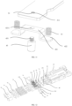
- FIG. 13 is a schematic diagram showing a synchronizing swing arm in accordance with an embodiment of the present invention.
- the synchronizing swing arm 51 includes a gear portion 512 and a third body portion 513, and the gear portion 512 and the connection shaft 511 are located at two ends of the third body portion 513, correspondingly.
- the gear portions 512 of the two synchronizing swing arms 51 engage, so that the gear portions 512 of the two synchronizing swing arms 51 cooperate with each other to enable the two synchronizing swing arms 51 to rotate synchronously.
- the synchronization assembly 50 includes a plurality of synchronizing gears 52 that engage with each other, and the gear portions 512 of the two synchronizing swing arms 51 are transmissively coupled by the plurality of synchronizing gears 52.
- the other synchronizing swing arm 51 is driven by the transmission of the plurality of synchronizing gears 52, thereby achieving a synchronous rotation of the two synchronizing swing arms 51.
- the foldable hinge further includes a plurality of mounting shafts 15 in the base 10. A part of the mounting shafts 15 are inserted in the gear portions 512 and circumferentially limited by the gear portions 512, and another part of the mounting shafts 15 are inserted in the synchronizing gears 52 and circumferentially limited by the synchronizing gears 52.
- the foldable hinge further includes a plurality of damping rings 60 fitted over the plurality of mounting shafts 15 correspondingly. The damping rings 60 are in interference fit with the mounting shafts 15, and the plurality of damping rings 60 are fixedly coupled to the base 10.
- FIG. 14 is a schematic diagram showing a mounting shaft in accordance with an embodiment of the present invention.
- the mounting shaft 15 includes a friction segment 151 and a mounting segment 152, and the friction segment 151 is at a first end of the mounting segment 152.
- the mounting segment 152 has a snap slot 153 at a second end of the mounting segment 152 away from the friction segment 151.
- the mounting segment 152 is used to cooperate with the gear portion 512 or the synchronizing gear 52, which is fitted over the mounting segment 152.
- the mounting segment 152 has a polygonal cross-section, and the mounting segment 152 is inserted into the gear portion 512 or the synchronizing gear 52 and can form a circumferential limitation or stop with the gear portion 512 or the synchronizing gear 52. Relative to the gear portion 512 or the synchronizing gear 52, the mounting shaft 15 is circumferentially stationary fitted over the mounting segment 152, but can perform an axial relative displacement.
- the side wall of the base 10 has a damping ring mounting hole 16, and the damping ring 60 is fixedly mounted in the damping ring mounting hole 16.
- the friction segment 151 of the mounting shaft 15 is mounted in the damping ring 60.
- FIG. 15 is a schematic diagram showing a damping ring in accordance with an embodiment of the present invention.
- the damping ring 60 includes a C-shaped segment 61 and a turnup segment 62, and the cross-section of the damping ring 60 has an open ring structure to facilitate the installation of the friction segment 151 into the damping ring 60.
- the C-shaped segment 61 is a columnar structure with a C-shaped cross-section, and the turnup segment 62 is coupled to both ends of the C-shaped segment 61.
- the cross-sectional shape of the damping ring 60 matches the shape of the damping ring mounting hole 16, and the turnup segment 62 is used to cooperate with the damping ring mounting hole 16 to limit the damping ring 60 and avoid the rotation of the damping ring 60.
- the C-shaped segment 61 is fitted over the friction segment 151.
- An outer diameter D1 of the friction segment 151 is greater than an inner diameter D2 of the C-shaped segment 61, enabling the C-shaped segment 61 to form an interference fit with the friction segment 151.
- the damping ring 60 may be a metal member, which has strong plasticity and is easy to bend into a corresponding shape.
- the synchronizing swing arms 51 also rotate. Since the mounting shaft 15 is circumferentially limited by the gear portion 512, the synchronizing swing arm 51 may drive the mounting shaft 15 to rotate, driving the mounting shaft 15 to rotate relative to the damping ring 60.
- the outer diameter D1 of the friction segment 151 is larger than the inner diameter D2 of the C-shaped segment 61, so that the damping ring 60 forms the interference fit with the friction segment 151 and the damping ring 16 grips the friction segment 151.
- the friction between the damping ring 60 and the friction segment 151 allows the two folding assemblies 20 to remain in their current state as long as no sufficiently large external force for folding is applied.
- the electronic device can hover at any angle within a range of angles at which it can be opened and closed.
- the foldable hinge also includes two self-locking plates 71, a locking spring 72, a spring stop 73, a snap plate 74, and an insertion tail plate 75.
- Both self-locking plates 71 are fitted over the mounting segment 152 of the mounting shaft 15, with one of the self-locking plates 71 abutting an end of the friction segment 151.
- the gear portion 512 of the synchronizing swing arm 51 is fitted over the mounting segment 152 and is between the two self-locking plates 71.
- the locking spring 72 and the spring stop 73 are sequentially fitted over the mounting segment 152.
- the locking spring 72 is on a side of the two self-locking plates 71 away from the mounting segment 152 and abuts against one of the two self-locking plates 71 which is farther away from the mounting segment 152.
- the spring stop 73 is at an end of the locking spring 72 away from the self-locking plate 71 and abuts against the locking spring 72.
- the snap plate 74 is snapped at the snap slot 153.
- the foldable hinge also includes the insertion tail plate 75 coupled to the base 10.
- the insertion tail plate 75 is at an end of the mounting shaft 15 away from the friction segment 151.
- the insertion tail plate 75 is used to axially limit the mounting shaft 15 to prevent the mounting shaft 15 from coming out of the damping ring 60 under a spring force of the locking spring 72.
- FIG. 16 is a schematic diagram showing a self-locking plate in accordance with an embodiment of the present invention.
- the self-locking plate 71 has a plurality of mounting holes 711, and the mounting shafts 15 are coaxially inserted in the mounting holes 711 of the self-locking plate 71, and the mounting shafts 15 and the self-locking plate 71 have a clearance fit.
- a side wall of the self-locking plate 71 close to the gear portion 512 has a plurality of recesses 712 distributed circumferentially around the mounting holes 711. Referring to FIG.
- two ends of the gear portion 512 of the synchronizing swing arm 51 have a plurality of bosses 514, and the plurality of bosses 514 are distributed circumferentially around the two ends of the gear portion 512.
- the plurality of bosses 514 can engage with the plurality of recesses 712 to achieve cooperation between the synchronizing swing arm 51 with the two self-locking plates 71.
- the synchronizing gear 52 may also have a plurality of bosses 514 at two ends of the synchronizing gear 52, and the bosses 514 at the ends of the synchronizing gear 52 are fit in the corresponding recesses 712 around the mounting hole 711 in the self-locking plate 71.
- the plurality of bosses 514 are within the plurality of recesses 712.
- a sufficiently large external force is applied to perform the folding, so that the bosses 514 slide out of the recesses 712, the locking spring 72 is compressed, and the two self-locking plates 71 move away from each other. Since one of the self-locking plates 71 abuts against the end of the friction segment 151 of the mounting shaft 15, this self-locking plate 71 may drive the mounting shaft 15 to move axially when this self-locking plate 71 moves away from the gear portion 512 of the synchronizing swing arm 51, causing the mounting shaft 15 to move into the damping ring 60.
- the snap plate 74 Since the snap plate 74 is snapped in the snap slot 153 of the mounting shaft 15, the snap plate 74 is fixed relative to the mounting shaft 15. When the mounting shaft 15 moves, the snap plate 74 squeezes the locking spring 72 through the spring stop 73.
- the spring force of the locking spring 72 is equivalent to a resistance, which hinders the rotation of the synchronizing swing arm 51. That is, the electronic device cannot be folded when the external force is not sufficient to overcome the spring force of the locking spring 72, such that the foldable hinge can lock the electronic device in the unfolded state.
- the foldable hinge when the foldable hinge is in the folded state, the plurality of bosses 514 are within the plurality of recesses 712, such that the foldable hinge can lock the electronic device in the folded state.
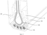
- FIG. 17 is a schematic diagram showing an electronic device in accordance with an embodiment of the present invention.
- the electronic device includes two housings 100, a flexible screen 200, and a foldable hinge 300.
- the two housings 100 are coupled to rotating arms 22 of the two folding assemblies 20 correspondingly, and the flexible screen 200 is coupled to the two housings 100.
- two ends of the flexible screen 200 are coupled to the two housings 100 correspondingly. Since the support member 21 is slidable relative to the base in the direction approaching/towards and away from the base 10 during folding and unfolding of the foldable hinge, and the support member 21 is rotatably arranged on the rotating arm 22, the support member 21 can perform sliding and rotating actions relative to the base 10 during folding and unfolding of the two housings 100. Thus, during the folding and unfolding process, an action trajectory of the two support members 21 follow a folding and unfolding trajectory of the flexible screen 200.
- a distance between portions of two support members 21 coupled to the rotating arms 22 is smaller than a distance between portions of the two support members 21 coupled to the base 10, and the two support members 21 and the base 10 enclose a drop-shaped receiving space. No squeeze, no compression or damage will be applied to the flexible screen 200 when the flexible screen 200 is received in the drop-shaped receiving space.
- the drop-shaped receiving space is also conducive to the use effect and stability of the mobile terminal.
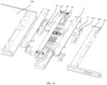
- FIG. 18 is an exploded view of an electronic device in accordance with an embodiment of the present invention.
- the housing 100 has a fixing hole 101 on a side of the housing 100 close to the rotating arm 22.
- the two rotating arms 22 are fixedly coupled to the two housings 100 by screws, correspondingly.
- screws are installed into the connection holes 221a of the rotating arms 22 and the fixing holes 101 of the housing 100 to couple the rotating arms 22 to the housing 100.
Landscapes
- Engineering & Computer Science (AREA)
- Theoretical Computer Science (AREA)
- Computer Hardware Design (AREA)
- General Engineering & Computer Science (AREA)
- Physics & Mathematics (AREA)
- General Physics & Mathematics (AREA)
- Mechanical Engineering (AREA)
- Human Computer Interaction (AREA)
- Telephone Set Structure (AREA)
- Casings For Electric Apparatus (AREA)
Claims (14)
- Ein klappbares Scharnier, das folgende Merkmale aufweist:eine Basis (10); undzwei Klappanordnungen (20) auf beiden Seiten der Basis (10) und mit der Basis (10) gekoppelt, wobei die zwei Klappanordnungen (20) relativ zueinander klappbar sind,wobei jede Klappanordnung (20) einen Dreharm (22) und ein Tragebauglied (21) aufweist, wobei ein erstes Ende des Dreharms (22) drehbar mit der Basis (10) gekoppelt ist, wobei das Tragebauglied (21) drehbar mit einem zweiten Ende des Dreharms (22) von der Basis (10) weg gekoppelt ist, wobei eine Seite des Tragebauglieds (21) nahe der Basis (10) drehbar mit der Basis (10) gekoppelt ist, und wobei das Tragebauglied (21) in einer Richtung zu oder weg von der Basis (10) verschiebbar ist; undwobei, wenn die zwei Klappanordnungen (20) zusammengebracht werden, ein Abstand (L1) zwischen Abschnitten der zwei Tragebauglieder (21), die mit den Dreharmen (22) gekoppelt sind, kleiner ist als ein Abstand (L2) zwischen Abschnitten der zwei Tragebauglieder (21), die mit der Basis (10) gekoppelt sind,wobei eine Oberfläche der Basis (10), die mit der Klappanordnung (20) gekoppelt ist, eine erste Kreisbogenrille (11) aufweist,der Dreharm (22) einen ersten Körperabschnitt (221) und einen ersten Bogenarm (222) aufweist, wobei ein Ende des ersten Bogenarms (222) mit dem ersten Körperabschnitt (221) gekoppelt ist, und wobei der erste Bogenarm (222) in der ersten Kreisbogenrille (11) ist und entlang der ersten Kreisbogenrille (11) verschiebbar ist,dadurch gekennzeichnet, dass:
die Oberfläche der Basis (10) ferner eine erste Ausnehmung (12) aufweist, die erste Ausnehmung (12) auf einer Seite der ersten Kreisbogenrille (11) ist, und eine Seitenwand der ersten Ausnehmung (12) einen Stiftschaft (13) aufweist, das Tragebauglied (21) einen Verbindungsblock (213) aufweist, der Verbindungsblock (213) des Tragebauglieds (21) in der ersten Ausnehmung (12) ist, und der Stiftschaft (13) in einem ersten Führungsgleitschlitz (2131) des Verbindungsblocks (213) ist. - Das klappbare Scharnier gemäß Anspruch 1, bei dem:der erste Körperabschnitt (221) eine zweite Kreisbogenrille (2211) aufweist, wobei eine Achse der zweiten Kreisbogenrille (2211) parallel zu einer Achse des ersten Bogenarms (222) ist; unddas Tragebauglied (21) eine erste Trageplatte (211) und einen zweiten Bogenarm (212) aufweist, wobei ein Ende des zweiten Bogenarms (212) mit der ersten Trageplatte (211) gekoppelt ist, und wobei der zweite Bogenarm (212) in der zweiten Kreisbogenrille (2211) ist und entlang der zweiten Kreisbogenrille (2211) verschiebbar ist.
- Das klappbare Scharnier gemäß Anspruch 2, bei dem:der Verbindungsblock (213) und der zweite Bogenarm (212) auf einer gemeinsamen Oberfläche der ersten Trageplatte (211) sind, und der Verbindungsblock (213) mit der ersten Trageplatte (211) gekoppelt ist; undeine halbmondförmige Seitenwand des Verbindungsblocks (213) den ersten Führungsgleitschlitz (2131) aufweist, und der erste Führungsgleitschlitz (2131) eine Kreisbogenform hat.
- Das klappbare Scharnier gemäß Anspruch 3, bei dem:ein Abschnitt (213a) des Verbindungsblocks (213) relativ zu einer Seitenkante der ersten Trageplatte (211) nahe der Basis (10) hervorsteht, und der Abschnitt (213a) des Verbindungsblocks (213) eine Trageoberfläche (2132) aufweist;das klappbare Scharnier ferner eine zweite Trageplatte (30) zwischen den zwei Klappanordnungen (20) aufweist, und die zweite Trageplatte (30) bewegbar mit der Basis (10) gekoppelt ist und relativ zu der Basis (10) in einer Richtung zu oder weg von der Basis (10) bewegbar ist;der Abschnitt (213a) des Verbindungsblocks (213) auf einer Seite der zweiten Trageplatte (30) nahe der Basis (10) ist, und die Trageoberfläche (2132) in Kontakt mit einer Oberfläche der zweiten Trageplatte (30) nahe der Basis (10) ist, ansprechend auf ein Aufklappen der zwei Klappanordnungen (20); unddie Trageoberfläche (2132) von der zweiten Trageplatte (30) getrennt ist, ansprechend auf ein Zusammenbringen der zwei Klappanordnungen (20).
- Das klappbare Scharnier gemäß Anspruch 4, bei dem:eine Oberfläche der Basis (10) nahe der zweiten Trageplatte (30) einen ersten Befestigungsschlitz (14) aufweist, und eine Seitenwand des ersten Montageschlitzes (14) eine Begrenzungsausnehmung (141) aufweist;das klappbare Scharnier ferner ein elastisches Bauglied (41) und eine Verbindungshalterung (42) aufweist; die Verbindungshalterung (42) einen zweiten Körperabschnitt (421) und einen Begrenzungsabschnitt (422) aufweist, wobei der zweite Körperabschnitt (421) in dem ersten Befestigungsschlitz (14) ist, und der Begrenzungsabschnitt (422) in der Begrenzungsausnehmung (141) ist; das elastische Bauglied (41) in der Begrenzungsausnehmung (141) ist, und das elastische Bauglied (41) zwischen dem Begrenzungsabschnitt (422) und einer Seitenwand der Begrenzungsausnehmung (141) ist; undder zweite Körperabschnitt (421) mit der zweiten Trageplatte (30) gekoppelt ist.
- Das klappbare Scharnier gemäß Anspruch 5, wobei das klappbare Scharnier ferner ein Führungsbauglied (43) aufweist; der erste Befestigungsschlitz (14) ein Führungsloch (142) in einem Boden des ersten Befestigungsschlitzes aufweist; und das Führungsbauglied (43) ein erstes Ende, das mit der Verbindungshalterung (42) gekoppelt ist, und ein zweites Ende aufweist, das in das Führungsloch (142) eingefügt ist.
- Das klappbare Scharnier gemäß einem der Ansprüche 1 bis 6, wobei das klappbare Scharnier ferner eine Synchronisationsanordnung (50) aufweist, die Synchronisationsanordnung (50) in der Basis (10) ist, und die Synchronisationsanordnung (50) mit den zwei Klappanordnungen (20) gekoppelt ist.
- Das klappbare Scharnier gemäß Anspruch 7, wobei die Synchronisationsanordnung (50) zwei Synchronisierschwingarme (51) aufweist, die sich entsprechend zu beiden Seiten der Basis (10) erstrecken; die zwei Synchronisierschwingarme (51) transmissiv gekoppelt sind; und jeder Synchronisierschwingarm (51) ein erstes Ende, das drehbar mit der Basis (10) gekoppelt ist, und ein zweites Ende aufweist, das gleitbar mit dem ersten Körperabschnitt (221) gekoppelt ist.
- Das klappbare Scharnier gemäß Anspruch 8, bei dem:der erste Körperabschnitt (221) eine zweite Ausnehmung (2212) auf einer Seitenwand des ersten Körperabschnitts nahe der Basis (10) aufweist, und eine Seitenwand der zweiten Ausnehmung (2212) einen zweiten Führungsgleitschlitz (2213) aufweist; unddas zweite Ende des Synchronisierschwingarms (51) entfernt von der Basis (10) einen Verbindungsschaft (511) aufweist, und der Verbindungsschaft (511) in dem zweiten Führungsgleitschlitz (2213) ist.
- Das klappbare Scharnier gemäß Anspruch 9, bei dem:der Synchronisierschwingarm (51) einen Zahnradabschnitt (512) und einen dritten Körperabschnitt (513) aufweist, und der Zahnradabschnitt (512) und der Verbindungsschaft (511) entsprechend an zwei Enden des dritten Körperabschnitts (513) sind; unddie Zahnradabschnitte (512) der zwei Synchronisierschwingarme (51) in einer Eingriff nehmenden Weise transmissiv gekoppelt sind.
- Das klappbare Scharnier gemäß Anspruch 10, das ferner einen Befestigungsschaft (15) in der Basis (10) und einen Dämpfungsring (60) aufweist, der über den Befestigungsschaft (15) gepasst ist,wobei der Befestigungsschaft (15) koaxial in den Zahnradabschnitt (512) eingefügt ist und in Umfangsrichtung durch den Zahnradabschnitt (512) begrenzt ist; undder Dämpfungsring (60) in Presspassung mit dem Befestigungsschaft (15) ist und fest mit der Basis (10) gekoppelt ist.
- Das klappbare Scharnier gemäß einem der Ansprüche 8 bis 10, wobei jede Synchronisationsanordnung (50) ferner eine Mehrzahl von Synchronisierzahnrädern (52) aufweist, die einander in Eingriff nehmen, und die Zahnradabschnitte (512) der zwei Synchronisierschwingarme (51) durch die Mehrzahl von Synchronisierzahnrädern (52) transmissiv gekoppelt sind.
- Das klappbare Scharnier gemäß Anspruch 12, das ferner einen Befestigungsschaft (15) in der Basis (10) und einen Dämpfungsring (60) aufweist, der über den Befestigungsschaft (15) gepasst ist,wobei der Befestigungsschaft (15) koaxial in das Synchronisierzahnrad (52) eingefügt ist und umfangsmäßig durch das Synchronisierzahnrad (52) begrenzt ist; undder Dämpfungsring (60) in Presspassung mit dem Befestigungsschaft (15) ist und fest mit der Basis (10) gekoppelt ist.
- Ein Elektronikgerät, das zwei Gehäuse (100), einen flexiblen Bildschirm (200) und das klappbare Scharnier (300) gemäß einem der Ansprüche 1 bis 13 aufweist,
wobei die zwei Gehäuse (100) entsprechend mit Dreharmen (22) der zwei Klappanordnungen (20) gekoppelt sind und der flexible Bildschirm (200) mit den zwei Gehäusen (100) gekoppelt ist.
Applications Claiming Priority (1)
| Application Number | Priority Date | Filing Date | Title |
|---|---|---|---|
| CN202111342141.8A CN116123207B (zh) | 2021-11-12 | 2021-11-12 | 折叠铰链和电子设备 |
Publications (2)
| Publication Number | Publication Date |
|---|---|
| EP4180909A1 EP4180909A1 (de) | 2023-05-17 |
| EP4180909B1 true EP4180909B1 (de) | 2025-01-29 |
Family
ID=81648843
Family Applications (1)
| Application Number | Title | Priority Date | Filing Date |
|---|---|---|---|
| EP22172888.4A Active EP4180909B1 (de) | 2021-11-12 | 2022-05-12 | Klappbares scharnier und elektronische vorrichtung |
Country Status (3)
| Country | Link |
|---|---|
| US (1) | US11977421B2 (de) |
| EP (1) | EP4180909B1 (de) |
| CN (1) | CN116123207B (de) |
Families Citing this family (19)
| Publication number | Priority date | Publication date | Assignee | Title |
|---|---|---|---|---|
| US12181932B2 (en) * | 2020-01-21 | 2024-12-31 | Google Llc | Multiple-axis hinge mechanism and foldable device having same |
| CN116972063B (zh) * | 2021-09-18 | 2024-08-30 | 荣耀终端有限公司 | 一种电子设备的折叠组件及电子设备 |
| CN116506538B (zh) * | 2022-01-18 | 2025-12-12 | 荣耀终端股份有限公司 | 电子设备 |
| US12306671B2 (en) * | 2022-06-03 | 2025-05-20 | Microsoft Technology Licensing, Llc | Timing mechanism for foldable computing device |
| EP4506778A4 (de) * | 2022-07-20 | 2025-07-30 | Samsung Electronics Co Ltd | Elektronische vorrichtung mit scharnierstruktur |
| CN117685286A (zh) * | 2022-09-02 | 2024-03-12 | 荣耀终端有限公司 | 折叠组件、折叠装置及终端设备 |
| TWI808037B (zh) * | 2022-11-10 | 2023-07-01 | 富世達股份有限公司 | 鉸鏈 |
| TWI853352B (zh) * | 2022-11-28 | 2024-08-21 | 富世達股份有限公司 | 鉸鏈 |
| TWI835429B (zh) * | 2022-11-28 | 2024-03-11 | 富世達股份有限公司 | 鉸鏈 |
| WO2024248799A1 (en) * | 2023-05-30 | 2024-12-05 | Google Llc | Folding portable display device |
| CN116576188B (zh) * | 2023-06-05 | 2025-11-14 | 维沃移动通信有限公司 | 铰链组件和电子设备 |
| CN119196157B (zh) * | 2023-06-26 | 2026-01-16 | 华为技术有限公司 | 一种铰链和可折叠设备 |
| JP2025007725A (ja) * | 2023-07-03 | 2025-01-17 | 株式会社ナチュラレーザ・ワン | ヒンジ保持装置、並びにこのヒンジ保持装置を用いた電子機器 |
| CN119445979A (zh) * | 2023-08-03 | 2025-02-14 | 北京小米移动软件有限公司 | 一种折叠机构、电子设备及其配件 |
| CN119641783A (zh) * | 2023-09-18 | 2025-03-18 | 富世达股份有限公司 | 铰链 |
| CN119860400B (zh) * | 2023-10-19 | 2026-01-06 | 华为技术有限公司 | 铰链装置、折叠装置及可折叠电子设备 |
| CN117351844B (zh) * | 2023-11-21 | 2024-04-09 | 荣耀终端有限公司 | 转动机构和可折叠电子设备 |
| CN120231823A (zh) * | 2023-12-28 | 2025-07-01 | 富世达股份有限公司 | 铰链 |
| CN117515017A (zh) * | 2024-01-04 | 2024-02-06 | 荣耀终端有限公司 | 转轴机构、支撑装置和折叠屏设备 |
Family Cites Families (36)
| Publication number | Priority date | Publication date | Assignee | Title |
|---|---|---|---|---|
| KR102322377B1 (ko) * | 2014-12-31 | 2021-11-05 | 엘지디스플레이 주식회사 | 접이식 디스플레이 장치 |
| CN108322567B (zh) * | 2018-02-01 | 2019-11-08 | 杭州安费诺飞凤通信部品有限公司 | 一种内折柔性屏移动终端的铰链及内折柔性屏移动终端 |
| TWI710308B (zh) * | 2019-02-16 | 2020-11-11 | 兆利科技工業股份有限公司 | 折疊式裝置的轉軸模組(四) |
| CN111692196B (zh) * | 2019-03-15 | 2021-10-22 | 华为技术有限公司 | 一种转轴机构及移动终端 |
| KR102296241B1 (ko) * | 2019-07-17 | 2021-09-01 | 주식회사 파인테크닉스 | 인폴딩 플렉시블 디스플레이 |
| CN114338864A (zh) * | 2020-09-30 | 2022-04-12 | 华为技术有限公司 | 折叠装置及电子设备 |
| CN112995368B (zh) * | 2019-12-13 | 2021-12-21 | 华为技术有限公司 | 一种铰链和移动终端 |
| KR102798666B1 (ko) * | 2019-12-13 | 2025-04-18 | 후아웨이 테크놀러지 컴퍼니 리미티드 | 회전축 구조체 및 전자 장치 |
| CN113090149B (zh) * | 2019-12-23 | 2022-08-09 | 北京小米移动软件有限公司 | 铰链结构和折叠式电子设备 |
| BR112022012734A2 (pt) * | 2019-12-27 | 2022-09-06 | Huawei Tech Co Ltd | Dispositivo eletrônico |
| US20230118440A1 (en) | 2020-02-24 | 2023-04-20 | Hewlett-Packard Development Company, L.P. | Foldable display screens |
| KR20210137286A (ko) * | 2020-05-07 | 2021-11-17 | 삼성디스플레이 주식회사 | 표시 장치 |
| CN113805646B (zh) * | 2020-06-15 | 2024-01-30 | 华为技术有限公司 | 折叠装置及电子设备 |
| CN111681548B (zh) * | 2020-06-15 | 2021-12-28 | 武汉华星光电半导体显示技术有限公司 | 可折叠显示装置 |
| CN212838936U (zh) * | 2020-06-19 | 2021-03-30 | 北京小米移动软件有限公司 | 铰链、铰链组件和折叠式电子设备 |
| KR102862341B1 (ko) * | 2020-09-03 | 2025-09-19 | 삼성전자주식회사 | 플렉서블 디스플레이를 포함하는 전자 장치 |
| CN112178042B (zh) * | 2020-09-16 | 2025-12-16 | 珠海格力电器股份有限公司 | 一种折叠铰链及电子设备 |
| KR102763252B1 (ko) * | 2020-09-24 | 2025-02-07 | 삼성전자주식회사 | 힌지 구조물 및 이를 포함하는 전자 장치 |
| CN114333566B (zh) * | 2020-09-30 | 2025-01-10 | 华为技术有限公司 | 一种折叠装置及电子设备 |
| US12181935B2 (en) * | 2020-10-29 | 2024-12-31 | Google Llc | Water drop-type hinge in a computing device having a flexible display |
| KR102822590B1 (ko) * | 2020-11-30 | 2025-06-18 | 엘지디스플레이 주식회사 | 폴더블 표시 장치 |
| US20230409090A1 (en) * | 2020-12-03 | 2023-12-21 | Fine M-Tec Co.,Ltd. | Hinge device of portable terminal with foldable structure |
| US11868182B2 (en) * | 2020-12-10 | 2024-01-09 | Boe Technology Group Co., Ltd. | Display device |
| JP7143457B2 (ja) * | 2021-01-19 | 2022-09-28 | レノボ・シンガポール・プライベート・リミテッド | 電子機器 |
| CN214465544U (zh) * | 2021-01-20 | 2021-10-22 | 拓米(成都)应用技术研究院有限公司 | 一种具有良好联动性和支撑性的折叠铰链机构 |
| KR102892033B1 (ko) * | 2021-02-10 | 2025-11-28 | 삼성전자주식회사 | 힌지 모듈 및 그를 포함하는 전자 장치 |
| CN113067923B (zh) * | 2021-03-19 | 2023-11-14 | 维沃移动通信有限公司 | 折叠机构及电子设备 |
| JP7189995B2 (ja) * | 2021-04-20 | 2022-12-14 | レノボ・シンガポール・プライベート・リミテッド | 電子機器 |
| CN113404767B (zh) * | 2021-07-05 | 2024-12-31 | 江苏精研科技股份有限公司 | 折叠铰链、折叠铰链机构及移动终端 |
| CN115704419B (zh) * | 2021-08-12 | 2025-04-22 | 北京小米移动软件有限公司 | 铰链组件和电子设备 |
| CN116168602B (zh) * | 2021-11-24 | 2026-01-16 | 北京小米移动软件有限公司 | 连接装置和终端设备 |
| US12396112B2 (en) * | 2021-12-31 | 2025-08-19 | Lg Display Co., Ltd. | Foldable display apparatus |
| US12336123B2 (en) * | 2022-01-24 | 2025-06-17 | E Ink Holdings Inc. | Foldable display device and supporting assembly thereof |
| KR20230156209A (ko) * | 2022-05-04 | 2023-11-14 | 삼성디스플레이 주식회사 | 유연 패널 검사용 지그 및 이를 포함하는 표시 장치 |
| TWM631213U (zh) * | 2022-05-12 | 2022-08-21 | 鑫禾科技股份有限公司 | 樞轉裝置 |
| US20230093901A1 (en) * | 2022-10-28 | 2023-03-30 | Intel Corporation | Hinge for a foldable electronic device and related methods |
-
2021
- 2021-11-12 CN CN202111342141.8A patent/CN116123207B/zh active Active
-
2022
- 2022-04-29 US US17/733,113 patent/US11977421B2/en active Active
- 2022-05-12 EP EP22172888.4A patent/EP4180909B1/de active Active
Also Published As
| Publication number | Publication date |
|---|---|
| US11977421B2 (en) | 2024-05-07 |
| CN116123207A (zh) | 2023-05-16 |
| CN116123207B (zh) | 2026-01-16 |
| EP4180909A1 (de) | 2023-05-17 |
| US20230151656A1 (en) | 2023-05-18 |
Similar Documents
| Publication | Publication Date | Title |
|---|---|---|
| EP4180909B1 (de) | Klappbares scharnier und elektronische vorrichtung | |
| US11336759B2 (en) | Rotating shaft mechanism and mobile terminal | |
| JP7538353B2 (ja) | ヒンジおよび裏折りフレキシブルスクリーンモバイル端末 | |
| US11889644B2 (en) | Hinge assembly and electronic device | |
| US11455017B2 (en) | Hinge for mobile terminal having an inwardly bendable flexible screen and mobile terminal having an inwardly bendable flexible screen | |
| US11416039B2 (en) | Complex moving/rotating pivot shaft device | |
| KR20220002630A (ko) | 힌지 기구 및 폴더블 이동 단말기 | |
| WO2023077756A1 (zh) | 铰链部件和电子设备 | |
| CN113898665A (zh) | 铰链组件和电子设备 | |
| WO2023143329A1 (zh) | 一种转轴机构及电子设备 | |
| CN112901649B (zh) | 一种三段式内折叠铰链 | |
| EP4318177A1 (de) | Scharnieranordnung und elektronische vorrichtung | |
| CN114198386B (zh) | 用于内折柔性屏移动终端的铰链 | |
| CN110905908B (zh) | 极高屏占比折叠显示设备的铰链结构及折叠显示设备 | |
| WO2023083039A1 (zh) | 折叠铰链和电子设备 | |
| WO2023197993A1 (zh) | 铰链机构和电子设备 | |
| EP4180677B1 (de) | Drehwellenmechanismus und elektronische vorrichtung | |
| CN111862801A (zh) | 内折柔性屏移动终端的铰链及内折柔性屏移动终端 | |
| CN209057247U (zh) | 外柔性屏移动终端铰链 | |
| US20250027531A1 (en) | Hinge mechanism and electronic device | |
| US20240323269A1 (en) | Rotating shaft mechanism and electronic device | |
| US20250165042A1 (en) | Hinge Mechanism and Electronic Device | |
| US20250238056A1 (en) | Hinge mechanism and electronic device | |
| US12487639B2 (en) | Rotating shaft mechanism and foldable display device including the same | |
| US20260006733A1 (en) | Folding Mechanism and Display Device |
Legal Events
| Date | Code | Title | Description |
|---|---|---|---|
| PUAI | Public reference made under article 153(3) epc to a published international application that has entered the european phase |
Free format text: ORIGINAL CODE: 0009012 |
|
| STAA | Information on the status of an ep patent application or granted ep patent |
Free format text: STATUS: REQUEST FOR EXAMINATION WAS MADE |
|
| 17P | Request for examination filed |
Effective date: 20220512 |
|
| AK | Designated contracting states |
Kind code of ref document: A1 Designated state(s): AL AT BE BG CH CY CZ DE DK EE ES FI FR GB GR HR HU IE IS IT LI LT LU LV MC MK MT NL NO PL PT RO RS SE SI SK SM TR |
|
| GRAP | Despatch of communication of intention to grant a patent |
Free format text: ORIGINAL CODE: EPIDOSNIGR1 |
|
| STAA | Information on the status of an ep patent application or granted ep patent |
Free format text: STATUS: GRANT OF PATENT IS INTENDED |
|
| INTG | Intention to grant announced |
Effective date: 20240919 |
|
| GRAS | Grant fee paid |
Free format text: ORIGINAL CODE: EPIDOSNIGR3 |
|
| GRAA | (expected) grant |
Free format text: ORIGINAL CODE: 0009210 |
|
| STAA | Information on the status of an ep patent application or granted ep patent |
Free format text: STATUS: THE PATENT HAS BEEN GRANTED |
|
| P01 | Opt-out of the competence of the unified patent court (upc) registered |
Free format text: CASE NUMBER: APP_64255/2024 Effective date: 20241204 |
|
| AK | Designated contracting states |
Kind code of ref document: B1 Designated state(s): AL AT BE BG CH CY CZ DE DK EE ES FI FR GB GR HR HU IE IS IT LI LT LU LV MC MK MT NL NO PL PT RO RS SE SI SK SM TR |
|
| REG | Reference to a national code |
Ref country code: GB Ref legal event code: FG4D |
|
| REG | Reference to a national code |
Ref country code: CH Ref legal event code: EP |
|
| REG | Reference to a national code |
Ref country code: DE Ref legal event code: R096 Ref document number: 602022009957 Country of ref document: DE |
|
| REG | Reference to a national code |
Ref country code: IE Ref legal event code: FG4D |
|
| REG | Reference to a national code |
Ref country code: NL Ref legal event code: MP Effective date: 20250129 |
|
| PG25 | Lapsed in a contracting state [announced via postgrant information from national office to epo] |
Ref country code: NL Free format text: LAPSE BECAUSE OF FAILURE TO SUBMIT A TRANSLATION OF THE DESCRIPTION OR TO PAY THE FEE WITHIN THE PRESCRIBED TIME-LIMIT Effective date: 20250129 |
|
| PG25 | Lapsed in a contracting state [announced via postgrant information from national office to epo] |
Ref country code: RS Free format text: LAPSE BECAUSE OF FAILURE TO SUBMIT A TRANSLATION OF THE DESCRIPTION OR TO PAY THE FEE WITHIN THE PRESCRIBED TIME-LIMIT Effective date: 20250429 |
|
| PG25 | Lapsed in a contracting state [announced via postgrant information from national office to epo] |
Ref country code: FI Free format text: LAPSE BECAUSE OF FAILURE TO SUBMIT A TRANSLATION OF THE DESCRIPTION OR TO PAY THE FEE WITHIN THE PRESCRIBED TIME-LIMIT Effective date: 20250129 |
|
| PG25 | Lapsed in a contracting state [announced via postgrant information from national office to epo] |
Ref country code: PL Free format text: LAPSE BECAUSE OF FAILURE TO SUBMIT A TRANSLATION OF THE DESCRIPTION OR TO PAY THE FEE WITHIN THE PRESCRIBED TIME-LIMIT Effective date: 20250129 |
|
| PG25 | Lapsed in a contracting state [announced via postgrant information from national office to epo] |
Ref country code: ES Free format text: LAPSE BECAUSE OF FAILURE TO SUBMIT A TRANSLATION OF THE DESCRIPTION OR TO PAY THE FEE WITHIN THE PRESCRIBED TIME-LIMIT Effective date: 20250129 |
|
| REG | Reference to a national code |
Ref country code: LT Ref legal event code: MG9D |
|
| PG25 | Lapsed in a contracting state [announced via postgrant information from national office to epo] |
Ref country code: NO Free format text: LAPSE BECAUSE OF FAILURE TO SUBMIT A TRANSLATION OF THE DESCRIPTION OR TO PAY THE FEE WITHIN THE PRESCRIBED TIME-LIMIT Effective date: 20250429 Ref country code: IS Free format text: LAPSE BECAUSE OF FAILURE TO SUBMIT A TRANSLATION OF THE DESCRIPTION OR TO PAY THE FEE WITHIN THE PRESCRIBED TIME-LIMIT Effective date: 20250529 |
|
| REG | Reference to a national code |
Ref country code: AT Ref legal event code: MK05 Ref document number: 1764077 Country of ref document: AT Kind code of ref document: T Effective date: 20250129 |
|
| PG25 | Lapsed in a contracting state [announced via postgrant information from national office to epo] |
Ref country code: HR Free format text: LAPSE BECAUSE OF FAILURE TO SUBMIT A TRANSLATION OF THE DESCRIPTION OR TO PAY THE FEE WITHIN THE PRESCRIBED TIME-LIMIT Effective date: 20250129 |
|
| PG25 | Lapsed in a contracting state [announced via postgrant information from national office to epo] |
Ref country code: PT Free format text: LAPSE BECAUSE OF FAILURE TO SUBMIT A TRANSLATION OF THE DESCRIPTION OR TO PAY THE FEE WITHIN THE PRESCRIBED TIME-LIMIT Effective date: 20250529 Ref country code: LV Free format text: LAPSE BECAUSE OF FAILURE TO SUBMIT A TRANSLATION OF THE DESCRIPTION OR TO PAY THE FEE WITHIN THE PRESCRIBED TIME-LIMIT Effective date: 20250129 |
|
| PG25 | Lapsed in a contracting state [announced via postgrant information from national office to epo] |
Ref country code: BG Free format text: LAPSE BECAUSE OF FAILURE TO SUBMIT A TRANSLATION OF THE DESCRIPTION OR TO PAY THE FEE WITHIN THE PRESCRIBED TIME-LIMIT Effective date: 20250129 Ref country code: GR Free format text: LAPSE BECAUSE OF FAILURE TO SUBMIT A TRANSLATION OF THE DESCRIPTION OR TO PAY THE FEE WITHIN THE PRESCRIBED TIME-LIMIT Effective date: 20250430 |
|
| PG25 | Lapsed in a contracting state [announced via postgrant information from national office to epo] |
Ref country code: AT Free format text: LAPSE BECAUSE OF FAILURE TO SUBMIT A TRANSLATION OF THE DESCRIPTION OR TO PAY THE FEE WITHIN THE PRESCRIBED TIME-LIMIT Effective date: 20250129 |
|
| PG25 | Lapsed in a contracting state [announced via postgrant information from national office to epo] |
Ref country code: SE Free format text: LAPSE BECAUSE OF FAILURE TO SUBMIT A TRANSLATION OF THE DESCRIPTION OR TO PAY THE FEE WITHIN THE PRESCRIBED TIME-LIMIT Effective date: 20250129 |
|
| PG25 | Lapsed in a contracting state [announced via postgrant information from national office to epo] |
Ref country code: SM Free format text: LAPSE BECAUSE OF FAILURE TO SUBMIT A TRANSLATION OF THE DESCRIPTION OR TO PAY THE FEE WITHIN THE PRESCRIBED TIME-LIMIT Effective date: 20250129 |
|
| PG25 | Lapsed in a contracting state [announced via postgrant information from national office to epo] |
Ref country code: DK Free format text: LAPSE BECAUSE OF FAILURE TO SUBMIT A TRANSLATION OF THE DESCRIPTION OR TO PAY THE FEE WITHIN THE PRESCRIBED TIME-LIMIT Effective date: 20250129 |
|
| PG25 | Lapsed in a contracting state [announced via postgrant information from national office to epo] |
Ref country code: IT Free format text: LAPSE BECAUSE OF FAILURE TO SUBMIT A TRANSLATION OF THE DESCRIPTION OR TO PAY THE FEE WITHIN THE PRESCRIBED TIME-LIMIT Effective date: 20250129 |
|
| PG25 | Lapsed in a contracting state [announced via postgrant information from national office to epo] |
Ref country code: CZ Free format text: LAPSE BECAUSE OF FAILURE TO SUBMIT A TRANSLATION OF THE DESCRIPTION OR TO PAY THE FEE WITHIN THE PRESCRIBED TIME-LIMIT Effective date: 20250129 Ref country code: EE Free format text: LAPSE BECAUSE OF FAILURE TO SUBMIT A TRANSLATION OF THE DESCRIPTION OR TO PAY THE FEE WITHIN THE PRESCRIBED TIME-LIMIT Effective date: 20250129 |
|
| PG25 | Lapsed in a contracting state [announced via postgrant information from national office to epo] |
Ref country code: RO Free format text: LAPSE BECAUSE OF FAILURE TO SUBMIT A TRANSLATION OF THE DESCRIPTION OR TO PAY THE FEE WITHIN THE PRESCRIBED TIME-LIMIT Effective date: 20250129 |
|
| PG25 | Lapsed in a contracting state [announced via postgrant information from national office to epo] |
Ref country code: SK Free format text: LAPSE BECAUSE OF FAILURE TO SUBMIT A TRANSLATION OF THE DESCRIPTION OR TO PAY THE FEE WITHIN THE PRESCRIBED TIME-LIMIT Effective date: 20250129 |
|
| REG | Reference to a national code |
Ref country code: DE Ref legal event code: R097 Ref document number: 602022009957 Country of ref document: DE |
|
| REG | Reference to a national code |
Ref country code: DE Ref legal event code: R119 Ref document number: 602022009957 Country of ref document: DE |
|
| PLBE | No opposition filed within time limit |
Free format text: ORIGINAL CODE: 0009261 |
|
| STAA | Information on the status of an ep patent application or granted ep patent |
Free format text: STATUS: NO OPPOSITION FILED WITHIN TIME LIMIT |
|
| REG | Reference to a national code |
Ref country code: CH Ref legal event code: L10 Free format text: ST27 STATUS EVENT CODE: U-0-0-L10-L00 (AS PROVIDED BY THE NATIONAL OFFICE) Effective date: 20251210 |
|
| REG | Reference to a national code |
Ref country code: CH Ref legal event code: H13 Free format text: ST27 STATUS EVENT CODE: U-0-0-H10-H13 (AS PROVIDED BY THE NATIONAL OFFICE) Effective date: 20251223 |
|
| 26N | No opposition filed |
Effective date: 20251030 |
|
| PG25 | Lapsed in a contracting state [announced via postgrant information from national office to epo] |
Ref country code: LU Free format text: LAPSE BECAUSE OF NON-PAYMENT OF DUE FEES Effective date: 20250512 |
|
| PG25 | Lapsed in a contracting state [announced via postgrant information from national office to epo] |
Ref country code: CH Free format text: LAPSE BECAUSE OF NON-PAYMENT OF DUE FEES Effective date: 20250531 |
|
| PG25 | Lapsed in a contracting state [announced via postgrant information from national office to epo] |
Ref country code: MC Free format text: LAPSE BECAUSE OF FAILURE TO SUBMIT A TRANSLATION OF THE DESCRIPTION OR TO PAY THE FEE WITHIN THE PRESCRIBED TIME-LIMIT Effective date: 20250129 |