EP4180792B1 - Verfahren zur bestimmung eines verstopfungszustandswerts eines probenfilters - Google Patents
Verfahren zur bestimmung eines verstopfungszustandswerts eines probenfilters Download PDFInfo
- Publication number
- EP4180792B1 EP4180792B1 EP21207382.9A EP21207382A EP4180792B1 EP 4180792 B1 EP4180792 B1 EP 4180792B1 EP 21207382 A EP21207382 A EP 21207382A EP 4180792 B1 EP4180792 B1 EP 4180792B1
- Authority
- EP
- European Patent Office
- Prior art keywords
- sample
- pump
- water
- value
- filter
- Prior art date
- Legal status (The legal status is an assumption and is not a legal conclusion. Google has not performed a legal analysis and makes no representation as to the accuracy of the status listed.)
- Active
Links
Images
Classifications
-
- B—PERFORMING OPERATIONS; TRANSPORTING
- B01—PHYSICAL OR CHEMICAL PROCESSES OR APPARATUS IN GENERAL
- B01D—SEPARATION
- B01D35/00—Filtering devices having features not specifically covered by groups B01D24/00 - B01D33/00, or for applications not specifically covered by groups B01D24/00 - B01D33/00; Auxiliary devices for filtration; Filter housing constructions
- B01D35/14—Safety devices specially adapted for filtration; Devices for indicating clogging
- B01D35/143—Filter condition indicators
-
- G—PHYSICS
- G01—MEASURING; TESTING
- G01N—INVESTIGATING OR ANALYSING MATERIALS BY DETERMINING THEIR CHEMICAL OR PHYSICAL PROPERTIES
- G01N1/00—Sampling; Preparing specimens for investigation
- G01N1/02—Devices for withdrawing samples
- G01N1/10—Devices for withdrawing samples in the liquid or fluent state
- G01N1/14—Suction devices, e.g. pumps; Ejector devices
-
- G—PHYSICS
- G01—MEASURING; TESTING
- G01N—INVESTIGATING OR ANALYSING MATERIALS BY DETERMINING THEIR CHEMICAL OR PHYSICAL PROPERTIES
- G01N33/00—Investigating or analysing materials by specific methods not covered by groups G01N1/00 - G01N31/00
- G01N33/18—Water
- G01N33/1886—Water using probes, e.g. submersible probes, buoys
-
- G—PHYSICS
- G01—MEASURING; TESTING
- G01F—MEASURING VOLUME, VOLUME FLOW, MASS FLOW OR LIQUID LEVEL; METERING BY VOLUME
- G01F11/00—Apparatus requiring external operation adapted at each repeated and identical operation to measure and separate a predetermined volume of fluid or fluent solid material from a supply or container, without regard to weight, and to deliver it
- G01F11/10—Apparatus requiring external operation adapted at each repeated and identical operation to measure and separate a predetermined volume of fluid or fluent solid material from a supply or container, without regard to weight, and to deliver it with measuring chambers moved during operation
- G01F11/12—Apparatus requiring external operation adapted at each repeated and identical operation to measure and separate a predetermined volume of fluid or fluent solid material from a supply or container, without regard to weight, and to deliver it with measuring chambers moved during operation of the valve type, i.e. the separating being effected by fluid-tight or powder-tight movements
- G01F11/125—Apparatus requiring external operation adapted at each repeated and identical operation to measure and separate a predetermined volume of fluid or fluent solid material from a supply or container, without regard to weight, and to deliver it with measuring chambers moved during operation of the valve type, i.e. the separating being effected by fluid-tight or powder-tight movements of the peristaltic pump type
Definitions
- the invention refers to a method for determining a sample filter clogging condition value of an immersion filter probe of a process water analyzer arrangement.
- a typical process water analyzer arrangement is disclosed in WO 2021 018 404 A1 .
- the process water analyzer arrangement is provided with a stationary immersion filter probe being immersed into a water basin and is provided with a land-based analyzing unit comprising a sample pump and a physical analyzer, e.g. a photometric analyzer, for analyzing the filtered water sample.
- the sample pump is typically provided as a peristaltic hose pump because this pump type is principally robust against clogging, and the pump hose being the only pump part coming into direct contact with the pumped water can easily be substituted.
- the pumping performance depends on the filter membrane clogging condition as well as on the pump hose condition. However, if no pressure sensor is provided, it is not possible to directly determine the transmembrane pressure which would be an indication for the filter clogging condition of the filter membrane.
- US 2016/200607 A1 discloses a waste water treatment plant incorporating a membrane bioreactor (MBR) system comprising among others a reactor tank, and a membrane filter unit submerged in a side tank of the reactor tank and fluidly connected to a permeate storage tank via a motor-driven peristaltic permeate feed pump. Clogging of the membrane filter unit is detected by reduced flow rate measured by rotameters or by transmembrane pressure drop (TMP) measured by a pressure transducer.
- MLR membrane bioreactor
- the method according to the invention refers to a process water analyzer arrangement comprising an immersion filter probe being arranged within a water basin and an analyzing unit comprising a water sample analyzer for analyzing a water sample filtered by the immersion filter probe.
- the preferably land-based analyzing unit comprises a bidirectional peristaltic hose sample pump for pumping the water sample from the immersion filter probe to the water sample analyzer.
- the peristaltic hose sample pump is fluidically arranged between the filter probe and the water sample analyzer, and can be driven in both fluidic directions, namely in forward and in backward direction.
- the sample pump comprises a flexible elastic peristaltic pump hose, a pump motor and a peristaltic pump rotor for providing a peristaltic deformation of the deformable flexible pump hose.
- the pump motor is controlled by a motor speed control so that the motor speed is known to the motor speed control. After starting the pump, the total number of pump rotor rotations is always known to the motor speed control.
- the arrangement comprises a bidirectional water flow sensor unit being arranged in-line with the filter probe, the sample pump and the water sample analyzer.
- the flow sensor unit is arranged downstream of the sample pump and upstream of the sample analyzer.
- the flow sensor precisely detects and determines a total flow volume in the range of several milliliters and with an accuracy of preferably at least 0.1 ml.
- the flow sensor can be used in forward pumping direction and in backward pumping direction.
- the immersion filter probe comprises a sample filter membrane being proximally mechanically supported by a support structure so that the sample filter membrane is perfectly mechanically supported and is not movable when the water is being pumped or sucked in forward direction through the sample filter membrane to the sample pump.
- the sample filter membrane is distally not perfectly mechanically supported and is bulged with a membrane distal bulging volume when water is pumped in backward direction from the sample pump to the filter probe. Since even a new sample filter membrane has a flow resistance of, for example, 100 mbar at a standard water flow rate in backward direction, the sample filter membrane is bulged at the beginning of a backward pumping action until the membrane distal bulging movement is finished because the filter membrane is completely tensed.
- the membrane distal bulging volume is only several milliliters and can be up to 20 ml.
- the typical bulging volume of the filter membrane is less than 10 ml.
- the process water analyzer arrangement comprises an electronic filter clogging condition determination module for determining a sample filter clogging condition value of the sample filter membrane.
- the clogging condition determination module is informationally connected to the sample pump and to the flow sensor unit by suitable signal connections.
- the clogging condition determination module can actively control the action of the sample pump.
- the filter clogging condition determination module provides the following method steps:
- the filter clogging condition determination module drives the sample pump with a known rotational speed for pumping a defined filtration volume flowing in the forward direction through the filter membrane, the pumping of the correct defined filtration volume being detected and controlled by the water flow sensor unit.
- the filtration motor rotations value for pumping the defined filtration volume is memorized in a suitable memory of the filter clogging condition determination module.
- the filtration motor rotations value is provided by the motor speed control.
- the sample pump is driven for pumping a defined non-filtration volume which volume is detected and controlled by the water flow sensor unit.
- the defined total non-filtration volume is at least minimally smaller than the membrane distal bulging volume so that there is no relevant transmembrane water flow during this method step.
- the motor rotations value for pumping the defined non-filtration volume is memorized by the filter clogging condition determination value module.
- the non-filtration volume is less than 10 ml.
- the pumping of the defined non-filtration volume can be provided in forward or in backward flow direction. If the filter membrane is completely bulged before the latter method step is started, the latter method step of pumping a defined non-filtration volume is provided in forward pumping direction. If the filter membrane is completely non-bulged and is completely in contact with the membrane support structure, the latter method step is provided in backward pumping direction.
- the sample pump must be of the bidirectional type.
- the sample pump is pumping in forward direction for pumping the defined filtration volume and is pumping in backward direction for pumping the defined non-filtration volume.
- the forward pumping direction generates a water flow from the filter probe to the sample pump
- the backward pumping direction generates a water flow from the sample pump to the filter probe.
- no pressure sensor is provided fluidically between the filter probe and the sample pump.
- the filter clogging condition determination module determines a sample filter clogging condition value based on the memorized filtration motor rotations value and the memorized non-filtration motor rotations value.
- the two said rotations values allow an indication of the sample filter clogging condition because the total number of motor rotations needed for pumping the non-filtration volume is substantially effected by the physical condition of the peristaltic hose of the sample pump, but is not substantially effected by the clogging condition of the filter membrane.
- the total number of motor rotations needed for pumping the defined filtration volume flowing through the filter membrane without bulging the filter membrane is effected by both, the physical condition of the peristaltic hose of the sample pump and the clogging condition of the filter membrane.
- the determination of the sample filter clogging condition value is based on the basic principle that the filter clogging condition value is the better the smaller the difference is between the filtration motor rotations value and the non-filtration motor rotations value or the smaller the ratio is of the filtration motor rotations value and the non-filtration motor rotations value.
- a good filter clogging condition value means that the filter membrane has a relatively low fluidic resistance in forward flow direction.
- the defined filtration volume is substantially equal or absolutely equal to the defined non-filtration volume.
- the water flow sensor unit is provided downstream of the sample pump.
- the water flow sensor unit can be provided with two sensor elements and determines the sample water travel time between the two sensor elements.
- the flow sensor unit comprises a vertical measuring container with two water level sensor elements being arranged in a vertical distance to each other. Since the analyzing unit of known process water analyzer arrangements generally are provided with a very precise vertical measuring container with two water level sensor elements, no additional elements are needed for providing a filter clogging condition determination module according to the invention.
- the pump motor driving the pump rotor is a step motor.
- a step motor allows a perfect control and recording of the pump rotor rotations, and allows to simply record and count the pump motor rotations and the pump rotor rotations without an additional motor sensor.
- a hydrostatic height memory is provided as part of the filter clogging condition determination module for memorizing the hydrostatic pump height value between the sample pump and the water surface in the water basin with the immersed immersion filter probe.
- the total height difference between the immersion filter probe and the sample pump effects the deformation of the pump hose during a pumping action so that the knowledge of the height difference is essential for a correct determination of the sample filter clogging condition value.
- the arrangement determines a hose condition value on the basis of the lately memorized non-filtration motor rotations value, for example, in relation to the same value of a new pump hose. If the determined non-filtration motor rotations value or the relation of the value with the corresponding value for a new hose exceeds a predefined difference or rate, a signal indicating a worn-out pump hose is generated and issued.
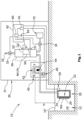
- FIG. 1 schematically shows a typical process water analyzer arrangement 10 being arranged at a water treatment plant comprising a water basin 12 filled with water 14.
- the process water analyzer arrangement 10 substantially comprises an immersion filter probe 20 arranged in the water basin 12 and a land-based analyzing unit 30.
- the analyzing unit 30 comprises within an analyzing unit housing 31, a bidirectional sample pump 40, a bidirectional water flow sensor unit 50, a filter clogging condition determination module 60 and a water sample analyzer 70.
- the water sample analyzer 70 is a photometer determining the transmission or the absorption of a water sample being treated by a suitable color-changing reagent and being pumped by the sample pump 40 to the sample analyzer 70.
- the water basin 12 is always filled with water 14 defining a water level surface 14' which is substantially at a constant level within the water basin 12.
- the immersion filter probe 20 is statically arranged in the water basin 12 at a constant vertical position and is provided with a sample filter membrane 24 being proximally supported by a membrane support structure 22 which can be, for example, a quadratic wire grid raster.
- the sample filter membrane 24 is completely immersed into the water 14.
- the distal side of the sample filter membrane 24 is not mechanically supported so that the membrane 24 can be bulged if the proximal membrane pressure is higher than the distal membrane pressure.
- the bulged sample filter membrane 24' defines a membrane distal bulging volume MV between the membrane support structure 22 and the bulged filter membrane 24'.
- the maximum membrane distal bulging volume MV is about 10 ml.
- the immersion filter probe 20 is provided with an external temperature sensor 29 for sensing the temperature of the basin water 14.
- the bidirectional peristaltic hose sample pump 40 comprises a pump motor 46 being a speed-controlled step motor, a peristaltic pump rotor 44 and a flexible elastic peristaltic pump hose 42 being continuously deformed by the cooperating rotating pump rotor 44.
- the sample pump 40 is fluidically arranged between the filter probe 20 and the water flow sensor unit 50, and can be driven in forward direction F for pumping a water sample to the water flow sensor unit 50 and the water sample analyzer 70 and in backward direction B for pumping water from the water flow sensor unit 50 back to the immersion filter probe 20.
- One full rotation of the pump rotor 44 pumps, under perfect conditions, 200 ⁇ l water per rotation, and pumps under worse conditions, less than 100 ⁇ l per rotation.
- the total pumping rate depends, among other factors, on the clogging of the sample filter membrane 24 and on the physical condition of the pump hose 42.
- the pump motor 46 is controlled by a motor speed control 61 being a part of a of an electronic analyzer control unit 62.
- No pressure sensor is provided fluidically between the filter probe 20 and the sample pump 40.
- the sample pump 40 is arranged in a hydrostatic pump height with a constant height value H above the basin water level 14' which value is memorized in a hydrostatic height memory 64 being a part of the analyzer control unit 62. After the water analyzer arrangement 10 has been mounted to the corresponding plant site, the hydrostatic pump height value H is entered manually into the hydrostatic height memory 64.
- the bidirectional water flow sensor unit 50 comprises a vertical cylindrical measuring container 56 with two separate water level sensor elements 51, 52 allowing to precisely detect a defined low water level 51' and a defined high water level 52' of the water within the measuring container 56.
- the container interior is fluidically connectable via a venting valve 32 to an atmospheric venting opening 33 for allowing the water level within the sensor unit container 56 to rise or to fall.
- the volume difference between the two water levels 51', 52' is, for example, exactly 2.00 ml which is exactly the value for a defined filtration volume FV and a defined non-filtration volume NV.
- a sample valve 34 is provided in the fluid line between the flow sensor unit 50 and the water sample analyzer 70, which sample valve 34 is closed during the filling or discharging the measuring container 56.
- the filter clogging condition determination module 60 After a filter condition determination has been triggered automatically or manually, for example once a day, the filter clogging condition determination module 60 provides the following method steps: For preparing the determination process, the filter clogging condition determination module 60 causes the sample pump 42 to rotate in forward direction F to ensure that the sample filter membrane 24 is completely in direct mechanical contact with the membrane support structure 22 and is not bulged.
- the container 56 of the water flow sensor unit 50 is filled precisely up to the upper water level 52' detected by the upper water level sensor element 52. The forward pumping action is completely stopped as soon as the upper water level 52' has been arrived detected by the upper water level sensor element 52.
- the sample pump 40 is driven by the motor control 61 speed-controlled in backward direction B, and the total number of rotations of the pump rotor 44 is counted and accumulated with a resolution of 72°/360° until the lower water level 51' is reached which is detected by the lower water level sensor element 51.
- a defined non-filtration volume NV of precisely 2.00 ml is pumped backwards to the filter probe 20. Since the filter membrane 24 has even in an unused new condition a relevant flow resistance for water, the water pumped backwards into the filter probe causes the filter membrane 24' to bulge but not to let the water pass the filter membrane 24'.
- the pumping performance of the sample pump 40 is not effected by the clogging condition of the filter membrane 24 but is effected by the known hydrostatic height H and the physical condition of the pump hose 42.
- the total number of motor rotor rotations needed for pumping the defined non-filtration volume NV is memorized in the filter clogging condition determination module 60 as a defined non-filtration motor rotations value NR.
- the sample pump 40 is caused to pump in forward direction F and the valves 32, 34 are switched to pump a volume of, for example 10 ml in forward direction F to the analyzer to ensure that the filter membrane 24, again, is in direct contact with the filter membrane support structure 22 and is not bulged anymore.
- the water in the water flow sensor unit 50 remains precisely at the lower water level 51' detected by the lower sensor element 51.
- the venting valve 32 is opened and the sample valve 34 is closed.
- the filter clogging condition determination module 60 now causes the sample pump 40 to pump in forward direction F the defined filtration volume FV of 2.00 ml which is detected by the upper sensor element 52, and to accumulate the filtration motor rotations value FR which is the total number of motor rotor rotations which is necessary to pump the defined filtration volume FV through the filter membrane 24.
- the pumping performance and the filtration motor rotations value FR depend on the filter clogging condition of the filter membrane 24, the known water temperature T detected by the temperature sensor 29, the known hydrostatic height H and the physical condition of the pump hose 42.
- the filter clogging condition determination module 60 can now determine the sample filter clogging condition value C based on the known filtration motor rotations value FR, the known water Temperature T and the known non-filtration motor rotations value NR.
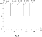
- Figure 2 shows a very schematic diagram which is memorized in the filter clogging condition determination module 60.
- the sample filter clogging condition value C is the better, the smaller the quotient FR/NR is.
- a motor rotations value of 5 corresponds with one full rotor rotation of 360°. If the non-filtration motor rotations value NR is above 100, which is 200% of the initial non-filtration motor rotations value 50 of a new pump hose, the peristaltic pump hose 42 is physically not in a good condition anymore and should be substituted. The relation of the latter two values is signalized as a pump hose condition value CH.
Landscapes
- Chemical & Material Sciences (AREA)
- Life Sciences & Earth Sciences (AREA)
- Health & Medical Sciences (AREA)
- General Health & Medical Sciences (AREA)
- Physics & Mathematics (AREA)
- Analytical Chemistry (AREA)
- Biochemistry (AREA)
- General Physics & Mathematics (AREA)
- Immunology (AREA)
- Pathology (AREA)
- Hydrology & Water Resources (AREA)
- Chemical Kinetics & Catalysis (AREA)
- Engineering & Computer Science (AREA)
- Food Science & Technology (AREA)
- Medicinal Chemistry (AREA)
- Separation Using Semi-Permeable Membranes (AREA)
Claims (13)
- Ein Verfahren zur Bestimmung eines Probenfilter-Verstopfungszustandswertes (C) einer Tauchfiltersonde (20) einer Prozess-Wasseranalysator-Anordnung (10),wobei die Anordnung (10) die in einem Wasserbecken (12) angeordnete Tauchfiltersonde (20) und eine Analyseeinheit (30) aufweist, die einen Wasserprobenanalysator (70) zum Analysieren einer durch die Tauchfiltersonde (20) gefilterten Wasserprobe aufweist,die Anordnung (10) eine bidirektionale Probenahmepumpe (40) mit peristaltischem Schlauch zum Pumpen einer Wasserprobe von der Tauchfiltersonde (20) zu dem Wasserprobenanalysator (70) aufweist, wobei die Probenahmepumpe (40) einen peristaltischen Pumpenschlauch (42) und einen Pumpenmotor (46) aufweist, der einen peristaltischen Pumpenrotor (44) antreibt, wobei der Pumpenmotor (46) durch eine Motordrehzahlregelung (61) drehzahlgeregelt ist,die Tauchfiltersonde (20) eine Probenfiltermembran (24) aufweist, die proximal mechanisch von einem Haltemittel (22) gehalten wird und ein distales Membran-Auswölbungsvolumen (MV) aufweist,die Anordnung (10) eine bidirektionale Wasserdurchfluss-Sensoreinheit (50) aufweist, die in Reihe mit der Probenahmepumpe (40) und dem Wasserprobenanalysator (70) angeordnet ist, unddie Anordnung (10) ein Filterverstopfungs-Bestimmungsmodul (60) zur Bestimmung des Probenfilter-Verstopfungszustandswertes (C) der Probenfiltermembran (24) aufweisend ist,mit den Verfahrensschritten, die das Filterverstopfungs-Bestimmungsmodul (60) ausführt:Steuern der Probenahmepumpe (40) mit einer bekannten Drehzahl zum Pumpen eines definierten Filtrationsvolumens (FV), das in Vorwärtsrichtung durch die Filtermembran (24) fließt und von der Wasserdurchfluss-Sensoreinheit (50) erfasst wird,Speichern des von der Motordrehzahlregelung (61) generierten Filtrationsmotor-Drehzahlwertes (FR) zum Pumpen des definierten Filtrationsvolumens (FV),Ansteuern der Probenahmepumpe (40) zum Pumpen eines definierten Nicht-Filtrationsvolumens (NV), das von der Wasserdurchfluss-Sensoreinheit (50) erfasst wird, wobei das Nicht-Filtrationsvolumen (NV) kleiner ist als das distale Membran-Auswölbungsvolumen (MV),Speichern des Motorumdrehungswertes (NR), der von der Motordrehzahlregelung (61) zum Pumpen des definierten Nicht-Filtrationsvolumens (NV) erzeugt wird, undBestimmen des Probenfilter-Verstopfungszustandswertes (C) auf der Grundlage des Filtrations-Motorumdrehungswertes (FR) und des NichtFiltrations-Motorumdrehungswertes (NR).
- Das Verfahren nach Anspruch 1, wobei die Probenahmepumpe (40) in Vorwärtsrichtung (F) pumpt, um das definierte Filtrationsvolumen (FV) zu pumpen, und in Rückwärtsrichtung (B) pumpt, um das definierte Nicht-Filtrationsvolumen (NV) zu pumpen.
- Das Verfahren nach einem der vorangehenden Ansprüche, wobei das definierte Filtrationsvolumen (FV) im Wesentlichen gleich dem definierten Nicht-Filtrationsvolumen (NV) ist.
- Das Verfahren nach einem der vorangehenden Ansprüche, wobei die Wasserdurchfluss-Sensoreinheit (50) stromabwärts der Probenahmepumpe (40) vorhanden ist.
- Das Verfahren nach einem der vorangehenden Ansprüche, wobei die Wasserdurchfluss-Sensoreinheit (50) zwei Sensorelemente (51, 52) aufweist und eine Laufzeit (T) zwischen den beiden Sensorelementen (51, 52) bestimmt.
- Das Verfahren nach einem der vorangehenden Ansprüche, wobei die Wasserdurchfluss-Sensoreinheit (50) einen vertikalen Messbehälter (56) mit zwei Wasserstands-Sensorelementen (51, 52) aufweist.
- Das Verfahren nach einem der vorangehenden Ansprüche, wobei das definierte Nicht-Filtrationsvolumen (NV) weniger als 10 ml beträgt.
- Das Verfahren nach einem der vorangehenden Ansprüche, wobei die Filtermembran (24) distal nicht mechanisch gestützt ist.
- Das Verfahren nach einem der vorangehenden Ansprüche, wobei fluidisch zwischen der Filtersonde (20) und der Probenahmepumpe (40) kein Drucksensor vorhanden ist.
- Das Verfahren nach einem der vorangehenden Ansprüche, wobei der Pumpenmotor (46) ein Schrittmotor ist.
- Das Verfahren nach einem der vorangehenden Ansprüche, wobei ein hydrostatischer Höhenspeicher (64) zum Speichern des hydrostatischen Pumpenhöhenwertes (H) zwischen der Probenahmepumpe (40) und der Wasseroberfläche (40') im Wasserbecken (12) vorgesehen ist, wobei die Bestimmung des Probenfilter-Verstopfungszustandswertes (C) die hydrostatische Pumpenhöhe (H) berücksichtigt.
- Das Verfahren nach einem der vorangehenden Ansprüche, wobei der Probenfilter-Verstopfungszustandswert (C) um so günstiger ist, je kleiner das Verhältnis zwischen dem Filtrations-Motorumdrehungswert (FR) und dem Nichtfiltrations-Motorumdrehungswert (NR) ist.
- Das Verfahren nach einem der vorhergehenden Ansprüche, wobei die Anordnung (10) einen Pumpenschlauch-Zustandswert (CH) auf der Basis des Nichtfiltrations-Motorumdrehungswertes (NR) bestimmt.
Priority Applications (3)
| Application Number | Priority Date | Filing Date | Title |
|---|---|---|---|
| EP21207382.9A EP4180792B1 (de) | 2021-11-10 | 2021-11-10 | Verfahren zur bestimmung eines verstopfungszustandswerts eines probenfilters |
| PCT/EP2022/080973 WO2023083744A1 (en) | 2021-11-10 | 2022-11-07 | A method for determining a sample filter clogging condition value |
| CN202280068037.0A CN118076873A (zh) | 2021-11-10 | 2022-11-07 | 一种用于确定样品过滤器堵塞状况值的方法 |
Applications Claiming Priority (1)
| Application Number | Priority Date | Filing Date | Title |
|---|---|---|---|
| EP21207382.9A EP4180792B1 (de) | 2021-11-10 | 2021-11-10 | Verfahren zur bestimmung eines verstopfungszustandswerts eines probenfilters |
Publications (2)
| Publication Number | Publication Date |
|---|---|
| EP4180792A1 EP4180792A1 (de) | 2023-05-17 |
| EP4180792B1 true EP4180792B1 (de) | 2024-06-12 |
Family
ID=78819760
Family Applications (1)
| Application Number | Title | Priority Date | Filing Date |
|---|---|---|---|
| EP21207382.9A Active EP4180792B1 (de) | 2021-11-10 | 2021-11-10 | Verfahren zur bestimmung eines verstopfungszustandswerts eines probenfilters |
Country Status (3)
| Country | Link |
|---|---|
| EP (1) | EP4180792B1 (de) |
| CN (1) | CN118076873A (de) |
| WO (1) | WO2023083744A1 (de) |
Family Cites Families (2)
| Publication number | Priority date | Publication date | Assignee | Title |
|---|---|---|---|---|
| US10392279B2 (en) * | 2015-01-14 | 2019-08-27 | Scientific Associates | Eductor-based membrane bioreactor |
| CN113993607A (zh) | 2019-08-01 | 2022-01-28 | 哈希朗格有限公司 | 水采样浸入式探头 |
-
2021
- 2021-11-10 EP EP21207382.9A patent/EP4180792B1/de active Active
-
2022
- 2022-11-07 WO PCT/EP2022/080973 patent/WO2023083744A1/en not_active Ceased
- 2022-11-07 CN CN202280068037.0A patent/CN118076873A/zh active Pending
Also Published As
| Publication number | Publication date |
|---|---|
| EP4180792A1 (de) | 2023-05-17 |
| CN118076873A (zh) | 2024-05-24 |
| WO2023083744A1 (en) | 2023-05-19 |
Similar Documents
| Publication | Publication Date | Title |
|---|---|---|
| US4606826A (en) | Apparatus for controlling ultrafiltration and method for the same | |
| EP1991863B1 (de) | Fluidisches system für ein fluss-zytometer | |
| US5702597A (en) | Device for preparing a treatment liquid by filtration | |
| EP2291207B1 (de) | Medizinischer flüssigkeitskreislauf mit einem niedrigstufendetektor 1 | |
| EP0591184B1 (de) | Apherese verfahren und vorrichtung dafuer | |
| EP1131559B1 (de) | Methode und einrichtung zur dichtigkeitsprüfung einer membranpumpe | |
| US20040231414A1 (en) | Method for detecting a liquid level in a container in a circuit and a dialysis machine for actuating the method | |
| US20050247121A1 (en) | Urine collection and monitoring system | |
| EP2830744B1 (de) | Mikrofluss-filtrationssystem und flussfiltrationsverfahren | |
| CA1111776A (en) | Method and apparatus for determining the amount of ultrafiltration during dialysis | |
| US20250020555A1 (en) | Sample preparation arrangement | |
| US10975349B2 (en) | Method and apparatus for continuous automated perfusion system harvesting from in-situ filtration probe | |
| JP4622575B2 (ja) | 気泡除去装置 | |
| EP4180792A1 (de) | Verfahren zur bestimmung eines verstopfungszustandswerts eines probenfilters | |
| SE426103B (sv) | Anordning for provtagning av vetska i samband med att vetskan ledes genom en ledning eller dylikt | |
| JPH06504698A (ja) | 液体流量を測定する方法および装置 | |
| JP7224219B2 (ja) | 血液浄化装置 | |
| WO2021112770A1 (en) | Autonomous dialysis control | |
| CN112972803B (zh) | 一种包括流量反馈装置的微透析系统 | |
| JP4427753B2 (ja) | 血液浄化装置 | |
| US12553762B2 (en) | Liquid level detectors | |
| CN113551727B (zh) | 转桶式大坝渗流量仪及其控制方法 | |
| US12631173B2 (en) | Method for determining malfunction of a liquid drainage pump and related control device and liquid drainage pump | |
| US20250215873A1 (en) | Method for determining malfunction of a liquid drainage pump and related control device and liquid drainage pump | |
| JPH0622622B2 (ja) | 血液浄化装置 |
Legal Events
| Date | Code | Title | Description |
|---|---|---|---|
| PUAI | Public reference made under article 153(3) epc to a published international application that has entered the european phase |
Free format text: ORIGINAL CODE: 0009012 |
|
| STAA | Information on the status of an ep patent application or granted ep patent |
Free format text: STATUS: THE APPLICATION HAS BEEN PUBLISHED |
|
| AK | Designated contracting states |
Kind code of ref document: A1 Designated state(s): AL AT BE BG CH CY CZ DE DK EE ES FI FR GB GR HR HU IE IS IT LI LT LU LV MC MK MT NL NO PL PT RO RS SE SI SK SM TR |
|
| STAA | Information on the status of an ep patent application or granted ep patent |
Free format text: STATUS: REQUEST FOR EXAMINATION WAS MADE |
|
| 17P | Request for examination filed |
Effective date: 20231116 |
|
| RBV | Designated contracting states (corrected) |
Designated state(s): AL AT BE BG CH CY CZ DE DK EE ES FI FR GB GR HR HU IE IS IT LI LT LU LV MC MK MT NL NO PL PT RO RS SE SI SK SM TR |
|
| GRAP | Despatch of communication of intention to grant a patent |
Free format text: ORIGINAL CODE: EPIDOSNIGR1 |
|
| STAA | Information on the status of an ep patent application or granted ep patent |
Free format text: STATUS: GRANT OF PATENT IS INTENDED |
|
| RIC1 | Information provided on ipc code assigned before grant |
Ipc: G01F 11/12 20060101ALN20231205BHEP Ipc: B01D 35/143 20060101ALI20231205BHEP Ipc: G01N 33/18 20060101ALI20231205BHEP Ipc: G01N 1/14 20060101AFI20231205BHEP |
|
| INTG | Intention to grant announced |
Effective date: 20240105 |
|
| RIC1 | Information provided on ipc code assigned before grant |
Ipc: G01F 11/12 20060101ALN20231215BHEP Ipc: B01D 35/143 20060101ALI20231215BHEP Ipc: G01N 33/18 20060101ALI20231215BHEP Ipc: G01N 1/14 20060101AFI20231215BHEP |
|
| GRAS | Grant fee paid |
Free format text: ORIGINAL CODE: EPIDOSNIGR3 |
|
| GRAA | (expected) grant |
Free format text: ORIGINAL CODE: 0009210 |
|
| STAA | Information on the status of an ep patent application or granted ep patent |
Free format text: STATUS: THE PATENT HAS BEEN GRANTED |
|
| AK | Designated contracting states |
Kind code of ref document: B1 Designated state(s): AL AT BE BG CH CY CZ DE DK EE ES FI FR GB GR HR HU IE IS IT LI LT LU LV MC MK MT NL NO PL PT RO RS SE SI SK SM TR |
|
| REG | Reference to a national code |
Ref country code: GB Ref legal event code: FG4D |
|
| REG | Reference to a national code |
Ref country code: CH Ref legal event code: EP |
|
| REG | Reference to a national code |
Ref country code: DE Ref legal event code: R096 Ref document number: 602021014295 Country of ref document: DE |
|
| REG | Reference to a national code |
Ref country code: IE Ref legal event code: FG4D |
|
| PG25 | Lapsed in a contracting state [announced via postgrant information from national office to epo] |
Ref country code: BG Free format text: LAPSE BECAUSE OF FAILURE TO SUBMIT A TRANSLATION OF THE DESCRIPTION OR TO PAY THE FEE WITHIN THE PRESCRIBED TIME-LIMIT Effective date: 20240612 |
|
| PG25 | Lapsed in a contracting state [announced via postgrant information from national office to epo] |
Ref country code: HR Free format text: LAPSE BECAUSE OF FAILURE TO SUBMIT A TRANSLATION OF THE DESCRIPTION OR TO PAY THE FEE WITHIN THE PRESCRIBED TIME-LIMIT Effective date: 20240612 Ref country code: FI Free format text: LAPSE BECAUSE OF FAILURE TO SUBMIT A TRANSLATION OF THE DESCRIPTION OR TO PAY THE FEE WITHIN THE PRESCRIBED TIME-LIMIT Effective date: 20240612 |
|
| REG | Reference to a national code |
Ref country code: LT Ref legal event code: MG9D |
|
| PG25 | Lapsed in a contracting state [announced via postgrant information from national office to epo] |
Ref country code: GR Free format text: LAPSE BECAUSE OF FAILURE TO SUBMIT A TRANSLATION OF THE DESCRIPTION OR TO PAY THE FEE WITHIN THE PRESCRIBED TIME-LIMIT Effective date: 20240913 |
|
| REG | Reference to a national code |
Ref country code: NL Ref legal event code: MP Effective date: 20240612 |
|
| PG25 | Lapsed in a contracting state [announced via postgrant information from national office to epo] |
Ref country code: ES Free format text: LAPSE BECAUSE OF FAILURE TO SUBMIT A TRANSLATION OF THE DESCRIPTION OR TO PAY THE FEE WITHIN THE PRESCRIBED TIME-LIMIT Effective date: 20240612 |
|
| PG25 | Lapsed in a contracting state [announced via postgrant information from national office to epo] |
Ref country code: LV Free format text: LAPSE BECAUSE OF FAILURE TO SUBMIT A TRANSLATION OF THE DESCRIPTION OR TO PAY THE FEE WITHIN THE PRESCRIBED TIME-LIMIT Effective date: 20240612 |
|
| PG25 | Lapsed in a contracting state [announced via postgrant information from national office to epo] |
Ref country code: NO Free format text: LAPSE BECAUSE OF FAILURE TO SUBMIT A TRANSLATION OF THE DESCRIPTION OR TO PAY THE FEE WITHIN THE PRESCRIBED TIME-LIMIT Effective date: 20240912 Ref country code: LV Free format text: LAPSE BECAUSE OF FAILURE TO SUBMIT A TRANSLATION OF THE DESCRIPTION OR TO PAY THE FEE WITHIN THE PRESCRIBED TIME-LIMIT Effective date: 20240612 Ref country code: HR Free format text: LAPSE BECAUSE OF FAILURE TO SUBMIT A TRANSLATION OF THE DESCRIPTION OR TO PAY THE FEE WITHIN THE PRESCRIBED TIME-LIMIT Effective date: 20240612 Ref country code: GR Free format text: LAPSE BECAUSE OF FAILURE TO SUBMIT A TRANSLATION OF THE DESCRIPTION OR TO PAY THE FEE WITHIN THE PRESCRIBED TIME-LIMIT Effective date: 20240913 Ref country code: FI Free format text: LAPSE BECAUSE OF FAILURE TO SUBMIT A TRANSLATION OF THE DESCRIPTION OR TO PAY THE FEE WITHIN THE PRESCRIBED TIME-LIMIT Effective date: 20240612 Ref country code: ES Free format text: LAPSE BECAUSE OF FAILURE TO SUBMIT A TRANSLATION OF THE DESCRIPTION OR TO PAY THE FEE WITHIN THE PRESCRIBED TIME-LIMIT Effective date: 20240612 Ref country code: BG Free format text: LAPSE BECAUSE OF FAILURE TO SUBMIT A TRANSLATION OF THE DESCRIPTION OR TO PAY THE FEE WITHIN THE PRESCRIBED TIME-LIMIT Effective date: 20240612 Ref country code: RS Free format text: LAPSE BECAUSE OF FAILURE TO SUBMIT A TRANSLATION OF THE DESCRIPTION OR TO PAY THE FEE WITHIN THE PRESCRIBED TIME-LIMIT Effective date: 20240912 |
|
| PG25 | Lapsed in a contracting state [announced via postgrant information from national office to epo] |
Ref country code: NL Free format text: LAPSE BECAUSE OF FAILURE TO SUBMIT A TRANSLATION OF THE DESCRIPTION OR TO PAY THE FEE WITHIN THE PRESCRIBED TIME-LIMIT Effective date: 20240612 |
|
| REG | Reference to a national code |
Ref country code: AT Ref legal event code: MK05 Ref document number: 1694662 Country of ref document: AT Kind code of ref document: T Effective date: 20240612 |
|
| PG25 | Lapsed in a contracting state [announced via postgrant information from national office to epo] |
Ref country code: NL Free format text: LAPSE BECAUSE OF FAILURE TO SUBMIT A TRANSLATION OF THE DESCRIPTION OR TO PAY THE FEE WITHIN THE PRESCRIBED TIME-LIMIT Effective date: 20240612 |
|
| PG25 | Lapsed in a contracting state [announced via postgrant information from national office to epo] |
Ref country code: PT Free format text: LAPSE BECAUSE OF FAILURE TO SUBMIT A TRANSLATION OF THE DESCRIPTION OR TO PAY THE FEE WITHIN THE PRESCRIBED TIME-LIMIT Effective date: 20241014 |
|
| PG25 | Lapsed in a contracting state [announced via postgrant information from national office to epo] |
Ref country code: PT Free format text: LAPSE BECAUSE OF FAILURE TO SUBMIT A TRANSLATION OF THE DESCRIPTION OR TO PAY THE FEE WITHIN THE PRESCRIBED TIME-LIMIT Effective date: 20241014 |
|
| PG25 | Lapsed in a contracting state [announced via postgrant information from national office to epo] |
Ref country code: PL Free format text: LAPSE BECAUSE OF FAILURE TO SUBMIT A TRANSLATION OF THE DESCRIPTION OR TO PAY THE FEE WITHIN THE PRESCRIBED TIME-LIMIT Effective date: 20240612 |
|
| PG25 | Lapsed in a contracting state [announced via postgrant information from national office to epo] |
Ref country code: EE Free format text: LAPSE BECAUSE OF FAILURE TO SUBMIT A TRANSLATION OF THE DESCRIPTION OR TO PAY THE FEE WITHIN THE PRESCRIBED TIME-LIMIT Effective date: 20240612 |
|
| PG25 | Lapsed in a contracting state [announced via postgrant information from national office to epo] |
Ref country code: IS Free format text: LAPSE BECAUSE OF FAILURE TO SUBMIT A TRANSLATION OF THE DESCRIPTION OR TO PAY THE FEE WITHIN THE PRESCRIBED TIME-LIMIT Effective date: 20241012 Ref country code: AT Free format text: LAPSE BECAUSE OF FAILURE TO SUBMIT A TRANSLATION OF THE DESCRIPTION OR TO PAY THE FEE WITHIN THE PRESCRIBED TIME-LIMIT Effective date: 20240612 |
|
| PG25 | Lapsed in a contracting state [announced via postgrant information from national office to epo] |
Ref country code: CZ Free format text: LAPSE BECAUSE OF FAILURE TO SUBMIT A TRANSLATION OF THE DESCRIPTION OR TO PAY THE FEE WITHIN THE PRESCRIBED TIME-LIMIT Effective date: 20240612 |
|
| PG25 | Lapsed in a contracting state [announced via postgrant information from national office to epo] |
Ref country code: SK Free format text: LAPSE BECAUSE OF FAILURE TO SUBMIT A TRANSLATION OF THE DESCRIPTION OR TO PAY THE FEE WITHIN THE PRESCRIBED TIME-LIMIT Effective date: 20240612 Ref country code: RO Free format text: LAPSE BECAUSE OF FAILURE TO SUBMIT A TRANSLATION OF THE DESCRIPTION OR TO PAY THE FEE WITHIN THE PRESCRIBED TIME-LIMIT Effective date: 20240612 |
|
| PG25 | Lapsed in a contracting state [announced via postgrant information from national office to epo] |
Ref country code: SM Free format text: LAPSE BECAUSE OF FAILURE TO SUBMIT A TRANSLATION OF THE DESCRIPTION OR TO PAY THE FEE WITHIN THE PRESCRIBED TIME-LIMIT Effective date: 20240612 |
|
| PG25 | Lapsed in a contracting state [announced via postgrant information from national office to epo] |
Ref country code: SM Free format text: LAPSE BECAUSE OF FAILURE TO SUBMIT A TRANSLATION OF THE DESCRIPTION OR TO PAY THE FEE WITHIN THE PRESCRIBED TIME-LIMIT Effective date: 20240612 Ref country code: SK Free format text: LAPSE BECAUSE OF FAILURE TO SUBMIT A TRANSLATION OF THE DESCRIPTION OR TO PAY THE FEE WITHIN THE PRESCRIBED TIME-LIMIT Effective date: 20240612 Ref country code: RO Free format text: LAPSE BECAUSE OF FAILURE TO SUBMIT A TRANSLATION OF THE DESCRIPTION OR TO PAY THE FEE WITHIN THE PRESCRIBED TIME-LIMIT Effective date: 20240612 Ref country code: PL Free format text: LAPSE BECAUSE OF FAILURE TO SUBMIT A TRANSLATION OF THE DESCRIPTION OR TO PAY THE FEE WITHIN THE PRESCRIBED TIME-LIMIT Effective date: 20240612 Ref country code: IS Free format text: LAPSE BECAUSE OF FAILURE TO SUBMIT A TRANSLATION OF THE DESCRIPTION OR TO PAY THE FEE WITHIN THE PRESCRIBED TIME-LIMIT Effective date: 20241012 Ref country code: EE Free format text: LAPSE BECAUSE OF FAILURE TO SUBMIT A TRANSLATION OF THE DESCRIPTION OR TO PAY THE FEE WITHIN THE PRESCRIBED TIME-LIMIT Effective date: 20240612 Ref country code: CZ Free format text: LAPSE BECAUSE OF FAILURE TO SUBMIT A TRANSLATION OF THE DESCRIPTION OR TO PAY THE FEE WITHIN THE PRESCRIBED TIME-LIMIT Effective date: 20240612 Ref country code: AT Free format text: LAPSE BECAUSE OF FAILURE TO SUBMIT A TRANSLATION OF THE DESCRIPTION OR TO PAY THE FEE WITHIN THE PRESCRIBED TIME-LIMIT Effective date: 20240612 |
|
| PG25 | Lapsed in a contracting state [announced via postgrant information from national office to epo] |
Ref country code: IT Free format text: LAPSE BECAUSE OF FAILURE TO SUBMIT A TRANSLATION OF THE DESCRIPTION OR TO PAY THE FEE WITHIN THE PRESCRIBED TIME-LIMIT Effective date: 20240612 |
|
| REG | Reference to a national code |
Ref country code: DE Ref legal event code: R082 Ref document number: 602021014295 Country of ref document: DE Representative=s name: TERPATENT PARTGMBB, DE |
|
| REG | Reference to a national code |
Ref country code: DE Ref legal event code: R097 Ref document number: 602021014295 Country of ref document: DE |
|
| PG25 | Lapsed in a contracting state [announced via postgrant information from national office to epo] |
Ref country code: DK Free format text: LAPSE BECAUSE OF FAILURE TO SUBMIT A TRANSLATION OF THE DESCRIPTION OR TO PAY THE FEE WITHIN THE PRESCRIBED TIME-LIMIT Effective date: 20240612 |
|
| PLBE | No opposition filed within time limit |
Free format text: ORIGINAL CODE: 0009261 |
|
| STAA | Information on the status of an ep patent application or granted ep patent |
Free format text: STATUS: NO OPPOSITION FILED WITHIN TIME LIMIT |
|
| 26N | No opposition filed |
Effective date: 20250313 |
|
| REG | Reference to a national code |
Ref country code: CH Ref legal event code: PL |
|
| PG25 | Lapsed in a contracting state [announced via postgrant information from national office to epo] |
Ref country code: MC Free format text: LAPSE BECAUSE OF FAILURE TO SUBMIT A TRANSLATION OF THE DESCRIPTION OR TO PAY THE FEE WITHIN THE PRESCRIBED TIME-LIMIT Effective date: 20240612 |
|
| PG25 | Lapsed in a contracting state [announced via postgrant information from national office to epo] |
Ref country code: LU Free format text: LAPSE BECAUSE OF NON-PAYMENT OF DUE FEES Effective date: 20241110 |
|
| REG | Reference to a national code |
Ref country code: CH Ref legal event code: PL |
|
| PG25 | Lapsed in a contracting state [announced via postgrant information from national office to epo] |
Ref country code: CH Free format text: LAPSE BECAUSE OF NON-PAYMENT OF DUE FEES Effective date: 20241130 |
|
| REG | Reference to a national code |
Ref country code: BE Ref legal event code: MM Effective date: 20241130 |
|
| PG25 | Lapsed in a contracting state [announced via postgrant information from national office to epo] |
Ref country code: SE Free format text: LAPSE BECAUSE OF FAILURE TO SUBMIT A TRANSLATION OF THE DESCRIPTION OR TO PAY THE FEE WITHIN THE PRESCRIBED TIME-LIMIT Effective date: 20240612 |
|
| PG25 | Lapsed in a contracting state [announced via postgrant information from national office to epo] |
Ref country code: BE Free format text: LAPSE BECAUSE OF NON-PAYMENT OF DUE FEES Effective date: 20241130 |
|
| PG25 | Lapsed in a contracting state [announced via postgrant information from national office to epo] |
Ref country code: IE Free format text: LAPSE BECAUSE OF NON-PAYMENT OF DUE FEES Effective date: 20241110 |
|
| PGFP | Annual fee paid to national office [announced via postgrant information from national office to epo] |
Ref country code: DE Payment date: 20251119 Year of fee payment: 5 |
|
| PGFP | Annual fee paid to national office [announced via postgrant information from national office to epo] |
Ref country code: GB Payment date: 20251121 Year of fee payment: 5 |
|
| PGFP | Annual fee paid to national office [announced via postgrant information from national office to epo] |
Ref country code: FR Payment date: 20251126 Year of fee payment: 5 |
|
| PG25 | Lapsed in a contracting state [announced via postgrant information from national office to epo] |
Ref country code: HU Free format text: LAPSE BECAUSE OF FAILURE TO SUBMIT A TRANSLATION OF THE DESCRIPTION OR TO PAY THE FEE WITHIN THE PRESCRIBED TIME-LIMIT; INVALID AB INITIO Effective date: 20211110 |
|
| PG25 | Lapsed in a contracting state [announced via postgrant information from national office to epo] |
Ref country code: CY Free format text: LAPSE BECAUSE OF FAILURE TO SUBMIT A TRANSLATION OF THE DESCRIPTION OR TO PAY THE FEE WITHIN THE PRESCRIBED TIME-LIMIT; INVALID AB INITIO Effective date: 20211110 |