EP4180761B1 - Procédé de mesure d'outils - Google Patents
Procédé de mesure d'outils Download PDFInfo
- Publication number
- EP4180761B1 EP4180761B1 EP22188004.0A EP22188004A EP4180761B1 EP 4180761 B1 EP4180761 B1 EP 4180761B1 EP 22188004 A EP22188004 A EP 22188004A EP 4180761 B1 EP4180761 B1 EP 4180761B1
- Authority
- EP
- European Patent Office
- Prior art keywords
- tool
- axis
- image sensor
- light
- dimension
- Prior art date
- Legal status (The legal status is an assumption and is not a legal conclusion. Google has not performed a legal analysis and makes no representation as to the accuracy of the status listed.)
- Active
Links
Images


Classifications
-
- B—PERFORMING OPERATIONS; TRANSPORTING
- B23—MACHINE TOOLS; METAL-WORKING NOT OTHERWISE PROVIDED FOR
- B23Q—DETAILS, COMPONENTS, OR ACCESSORIES FOR MACHINE TOOLS, e.g. ARRANGEMENTS FOR COPYING OR CONTROLLING; MACHINE TOOLS IN GENERAL CHARACTERISED BY THE CONSTRUCTION OF PARTICULAR DETAILS OR COMPONENTS; COMBINATIONS OR ASSOCIATIONS OF METAL-WORKING MACHINES, NOT DIRECTED TO A PARTICULAR RESULT
- B23Q17/00—Arrangements for observing, indicating or measuring on machine tools
- B23Q17/24—Arrangements for observing, indicating or measuring on machine tools using optics or electromagnetic waves
- B23Q17/2452—Arrangements for observing, indicating or measuring on machine tools using optics or electromagnetic waves for measuring features or for detecting a condition of machine parts, tools or workpieces
- B23Q17/2457—Arrangements for observing, indicating or measuring on machine tools using optics or electromagnetic waves for measuring features or for detecting a condition of machine parts, tools or workpieces of tools
-
- G—PHYSICS
- G01—MEASURING; TESTING
- G01B—MEASURING LENGTH, THICKNESS OR SIMILAR LINEAR DIMENSIONS; MEASURING ANGLES; MEASURING AREAS; MEASURING IRREGULARITIES OF SURFACES OR CONTOURS
- G01B11/00—Measuring arrangements characterised by the use of optical techniques
- G01B11/002—Measuring arrangements characterised by the use of optical techniques for measuring two or more coordinates
- G01B11/005—Measuring arrangements characterised by the use of optical techniques for measuring two or more coordinates coordinate measuring machines
-
- G—PHYSICS
- G01—MEASURING; TESTING
- G01B—MEASURING LENGTH, THICKNESS OR SIMILAR LINEAR DIMENSIONS; MEASURING ANGLES; MEASURING AREAS; MEASURING IRREGULARITIES OF SURFACES OR CONTOURS
- G01B11/00—Measuring arrangements characterised by the use of optical techniques
- G01B11/02—Measuring arrangements characterised by the use of optical techniques for measuring length, width or thickness
- G01B11/026—Measuring arrangements characterised by the use of optical techniques for measuring length, width or thickness by measuring distance between sensor and object
-
- G—PHYSICS
- G01—MEASURING; TESTING
- G01B—MEASURING LENGTH, THICKNESS OR SIMILAR LINEAR DIMENSIONS; MEASURING ANGLES; MEASURING AREAS; MEASURING IRREGULARITIES OF SURFACES OR CONTOURS
- G01B11/00—Measuring arrangements characterised by the use of optical techniques
- G01B11/02—Measuring arrangements characterised by the use of optical techniques for measuring length, width or thickness
- G01B11/03—Measuring arrangements characterised by the use of optical techniques for measuring length, width or thickness by measuring coordinates of points
-
- G—PHYSICS
- G01—MEASURING; TESTING
- G01B—MEASURING LENGTH, THICKNESS OR SIMILAR LINEAR DIMENSIONS; MEASURING ANGLES; MEASURING AREAS; MEASURING IRREGULARITIES OF SURFACES OR CONTOURS
- G01B11/00—Measuring arrangements characterised by the use of optical techniques
- G01B11/24—Measuring arrangements characterised by the use of optical techniques for measuring contours or curvatures
- G01B11/25—Measuring arrangements characterised by the use of optical techniques for measuring contours or curvatures by projecting a pattern, e.g. one or more lines, moiré fringes on the object
- G01B11/2545—Measuring arrangements characterised by the use of optical techniques for measuring contours or curvatures by projecting a pattern, e.g. one or more lines, moiré fringes on the object with one projection direction and several detection directions, e.g. stereo
-
- B—PERFORMING OPERATIONS; TRANSPORTING
- B23—MACHINE TOOLS; METAL-WORKING NOT OTHERWISE PROVIDED FOR
- B23Q—DETAILS, COMPONENTS, OR ACCESSORIES FOR MACHINE TOOLS, e.g. ARRANGEMENTS FOR COPYING OR CONTROLLING; MACHINE TOOLS IN GENERAL CHARACTERISED BY THE CONSTRUCTION OF PARTICULAR DETAILS OR COMPONENTS; COMBINATIONS OR ASSOCIATIONS OF METAL-WORKING MACHINES, NOT DIRECTED TO A PARTICULAR RESULT
- B23Q17/00—Arrangements for observing, indicating or measuring on machine tools
- B23Q17/24—Arrangements for observing, indicating or measuring on machine tools using optics or electromagnetic waves
- B23Q17/2452—Arrangements for observing, indicating or measuring on machine tools using optics or electromagnetic waves for measuring features or for detecting a condition of machine parts, tools or workpieces
- B23Q17/2457—Arrangements for observing, indicating or measuring on machine tools using optics or electromagnetic waves for measuring features or for detecting a condition of machine parts, tools or workpieces of tools
- B23Q17/2461—Length
-
- B—PERFORMING OPERATIONS; TRANSPORTING
- B23—MACHINE TOOLS; METAL-WORKING NOT OTHERWISE PROVIDED FOR
- B23Q—DETAILS, COMPONENTS, OR ACCESSORIES FOR MACHINE TOOLS, e.g. ARRANGEMENTS FOR COPYING OR CONTROLLING; MACHINE TOOLS IN GENERAL CHARACTERISED BY THE CONSTRUCTION OF PARTICULAR DETAILS OR COMPONENTS; COMBINATIONS OR ASSOCIATIONS OF METAL-WORKING MACHINES, NOT DIRECTED TO A PARTICULAR RESULT
- B23Q17/00—Arrangements for observing, indicating or measuring on machine tools
- B23Q17/24—Arrangements for observing, indicating or measuring on machine tools using optics or electromagnetic waves
- B23Q17/2452—Arrangements for observing, indicating or measuring on machine tools using optics or electromagnetic waves for measuring features or for detecting a condition of machine parts, tools or workpieces
- B23Q17/2457—Arrangements for observing, indicating or measuring on machine tools using optics or electromagnetic waves for measuring features or for detecting a condition of machine parts, tools or workpieces of tools
- B23Q17/2466—Diameter
Definitions
- the invention relates to a method for measuring tools according to an optical principle according to claim 1.
- workpieces are often machined using cutting tools.
- the tools are usually measured with high accuracy at specified intervals. This is often done in a measuring machine or in inspection devices outside the machine tool.
- a method for checking a tool is known in which a laser measuring beam is shadowed by the tool.
- a laser beam receiver outputs a signal representative of the degree of shadowing.
- the invention is based on the object of creating a method by which at least one dimension of a tool with cutting edges can be determined with high precision, wherein the associated device can be operated in a processing space of a processing machine.
- a device suitable for carrying out the method serves to determine a dimension, for example the relevant diameter or length, of a tool with cutting edges.
- the device comprises a first light source such that light can be emitted from the first light source parallel to a first axis.
- the device further comprises an image sensor to which a second axis (optical axis) can be assigned, which runs orthogonally to the image sensor.
- the device comprises an evaluation unit, i.e., an electronic circuit for evaluating the signals supplied by the image sensor.
- the first axis and the second axis are arranged at an angle to one another, i.e., in particular, they are not aligned parallel to one another.
- the device is configured such that light emitted by the first light source can be reflected by the cutting edge of the tool such that the reflected light can generate sequential light points (or a reflective band) on the image sensor.
- the positions of the light points can be determined by the evaluation unit, wherein the dimension of the tool can be determined based on the positions of the light points on the image sensor.
- the determination of the tool's dimensions is therefore not performed using a transmitted-light method, in which a light source emits light parallel to the optical axis of the image sensor. Rather, the device is configured to use a dark-field method. This opens up the possibility of a device with the features of claim 1 being comparatively compact, yet still operating with high accuracy.
- the first light source can be configured to emit parallel light beams.
- a laser light source can be used that inherently emits parallel light beams or has collimating optics.
- the first light source can also emit bundled or converging light beams.
- LEDs particularly those with focusing optics, can advantageously be used.
- the first axis then preferably runs through the focal point of the first light source.
- the device is advantageously designed such that at least one reference coordinate can be stored in the evaluation unit, whereby the dimension of the tool can be determined by combining the position of at least one of the light points with the reference coordinate.
- the evaluation unit or the relevant electronic circuit is preferably located within the device. However, it can also be located outside the device; for example, a control system of the processing machine can include the evaluation unit, or it can be arranged in a separate device.
- the evaluation unit is configured in such a way that the dimensions of the tool can be determined by means of a compensation calculation based on the positions of several light points.
- the device is configured such that the first axis and the second axis intersect.
- the intersection angle between the first axis and the second axis is greater than 75°.
- the two axes thus intersect in space in such a way that two pairs of congruent vertex angles are created in the plane they spanned. The smaller of these two vertex angles is, according to generally accepted definitions, the intersection angle.
- the intersection angle of the respective axes in space can therefore be a maximum of 90°.
- the device is advantageously designed so that the intersection angle between the first axis and the second axis is 90°.
- the device is designed to be mounted on a surface of a machine table extending in a first plane.
- This first plane is oriented parallel to the second axis, with the first light source being arranged such that the first axis extends obliquely to the first plane. Accordingly, the first axis intersects the first plane at an angle other than 90°.
- first axis and the second axis extend in a second plane, wherein the second plane is inclined relative to the first plane by an angle greater than 20°, advantageously greater than 30° or greater than 40°.
- the device may comprise a second image acquisition unit having a second image sensor to which a third axis can be assigned, which is orthogonal to the second image sensor and to the second axis.
- the invention comprises a method for determining the dimensions of a tool with cutting edges.
- the light emitted by the first light source is reflected by the cutting edge of the tool in such a way that the reflected light creates a series of light points on the image sensor.
- the evaluation unit determines the positions of the light points, and the dimensions of the tool are determined based on the positions of the light points.
- the device is advantageously mounted in a machining room in which the tool will later be used to machine a workpiece is carried out.
- position values are determined that uniquely determine the position of the device in the processing space.
- a probing method is preferably used to determine the required position values.
- reference coordinates for the position of the image sensor and the orientation of the first axis in the processing space are determined. Accordingly, after this process step, the exact position and orientation of the image sensor in the coordinate system of the processing space are known.
- a reference body is connected to a tool holder of the processing machine.
- This reference body is then placed in front of the device and measured with the aid of the image sensor, i.e., its dimensions are determined, using the first light source.
- the reference body also has cutting edges or cutting-like edges.
- the tool is also connected to the tool holder of the processing machine.
- a correction value is generated, which contains the information of the exact position of the tool holder relative to the reference coordinates of the image sensor. The correction value is then stored, for example, in the evaluation unit or control system or in another device.
- the tool in particular one or more cutting edges of the tool, is qualitatively inspected before or after determining the tool dimensions.
- the device can, in particular, comprise a second image acquisition unit having a second image sensor.
- a third (optical) axis which runs orthogonally to the second image sensor and the second axis, can be assigned to the second image sensor. This allows a further view of the tool to be generated.
- the device also comprises a controller for processing control commands and their implementation in movement sequences of the tool holder in at least one directional axis. Furthermore, according to the further aspect, the device comprises at least one position measuring device for determining actual positions of the tool holder along the at least one directional axis. Corresponding actual position values or position signals of the tool holder or the tool attached thereto are fed to the controller for position control. The position measuring device is used to determine the position of the tool when determining the dimensions of the tool, i.e., outside of a machining process.
- the Figure 1 shows an embodiment of the device V.
- the device V comprises a first light source 1, here a laser diode, with a collimator 1.1.
- the first light source 1 emits light parallel to a first axis T.
- the device V further comprises an image sensor 2, for example a CMOS sensor or a CCD sensor.
- a lens is arranged in front of the image sensor 2, which lens is designed such that an entocentric image can be achieved on the image sensor 2.
- the image sensor 2 can be assigned a second axis Y, which is oriented orthogonally to the image sensor 2.
- a second light source 3 Radially adjacent to the image sensor 2 is a second light source 3, which in the presented embodiment is designed as a ring light consisting of several LEDs arranged around the second axis Y.
- the device V is intended to be mounted on a surface of a machine table extending in a first plane xy.
- This first plane xy is oriented parallel to the second axis Y, the first light source 1 being arranged such that the first axis T extends obliquely to the first plane xy.
- the first axis T and the second axis Y extend according to the Figure 1 in a second plane that is inclined relative to the first xy plane. In the presented embodiment, the angle between the first xy plane and the second plane is 45°.
- Both the image sensor 2 including the lens and the second light source 3 are covered by a transparent pane, which is circular in the presented embodiment.
- the device V is intended to be installed in a machining chamber of a machine tool or a processing machine. Contamination of the device V by cooling lubricants and/or chips is generally to be expected there. Such contaminants can be effectively removed from the transparent pane with the aid of compressed air flowing at high speed from nozzles of a first nozzle unit 5.
- the device V also has a third light source 4.
- the device V comprises a second image acquisition unit 7 which is arranged in the Figure 1 can be seen above.
- the image capture unit 7 has a second image sensor whose optical axis, hereinafter referred to as the third axis Z, is arranged perpendicular to the optical axis of the image sensor 2 or to the second axis Y.
- the second image capture unit 7 comprises a further, in particular annular, light source.
- a second nozzle unit 9 is mounted in the area of the second image capture unit 7, from which compressed air can flow.
- the device V has a fourth light source 8 in the area of the second image capture unit 7.
- the housing 6 which protects against external influences and is hermetically sealed.
- the housing 6 also contains a Figure 1 not shown evaluation unit 10 (see Figure 3 ).
- a tool W is shown, here a milling tool with helical cutting edges S, as well as an associated coordinate system with the directional axes x, y, z.
- the tool W rotates around a tool axis A during machining.
- D, H the diameter and length of the tool W, at predetermined time intervals, since these change due to wear during operation.
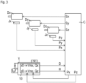
- the Figure 3 shows schematically elements of the processing machine, in particular a machine tool, as well as the device V for determining the dimensions D, H of the tool W.
- the processing machine comprises a controller C.
- the controller C serves, among other things, to process programmed control commands and to convert them into movement sequences.
- control signals Sx, Sy, Sz are transmitted from the controller C to drives Dx, Dy, Dz, which cause a tool holder, in particular with the tool W fixed thereto, to move along the first directional axis x, a second directional axis y and the third directional axis z ( Figure 1 ) in the machining area.
- the actual positions are determined by Position measuring devices Jx, Jy, Jz record the respective directional axes x, y, z.
- the corresponding actual position values of the tool W or position signals Px, Py, Pz are then fed to the control C for position control, as is usual with CNC machines.
- a corresponding processing machine can also have more than the three axes of movement mentioned above.
- the control signals Sx, Sy, Sz the dimensions D and H of the tool W must be taken into account so that material removal occurs exactly at the desired location on the workpiece. For this reason, tools were usually measured outside the processing area before the start of the machining process and the relevant dimensions were stored electronically in a table, preferably in the control C.
- step S1 the device V is first brought into the processing space and positioned there relatively roughly in a desired position, e.g., on a processing table.
- step S2 a probe is clamped into the tool holder of the processing machine, and several previously defined points on the housing 6 are probed to determine their position.
- This process step is carried out using a cycle stored in the control system C, which is essentially known in advance in connection with the usual measurement of the position of a workpiece blank.
- the absolute positions of the probed points are determined using the position measuring devices Jx, Jy, Jz.
- the position values Vx, Vy, Vz of the device V thus generated are fed to the control system C. Knowing the exact dimensions of the device V, the reference coordinates Vmx, Vmy, Vmz of the center of the image sensor 2 as well as the alignment TDC of the first axis T can now be determined in step S21 in the coordinate system of the processing machine.
- step S3 can be initiated directly after step S2.
- a reference body is clamped into the tool holder in the subsequent step S3.
- the exact dimensions Dr, Hr of this reference body which, for example, has a substantially cylindrical shape and has cutting-edge edges parallel to its longitudinal axis and in the circumferential direction, are known.
- the reference body is then brought into the intended measuring position, taking into account the determined reference coordinates Vmx, Vmy, Vmz of the center of the image sensor 2 and the alignment OT of the first axis T, with the tool holder preferably rotating with the reference body during the reference measurement.
- correction values Qx, Qy, Qz can be determined and stored in step S31. These correction values contain the information of the exact position of the tool holder or the tool axis A relative to the center of the image sensor 2 with the reference coordinates Vmx, Vmy, Vmz. Because the described determination of the correction values Qx, Qy, Qz takes place with the reference body or the tool holder rotating, errors related to the movement around the tool axis A are also implicitly taken into account later.
- the reference body can now be placed in the magazine of the processing machine and the tool W to be measured can be clamped into the tool holder.
- step S41 the tool W is first moved into the area of the second image acquisition unit 7.
- the nominal dimensions Dn, Hn of the tool W are first retrieved from a table stored in the controller C and read into the evaluation unit 10.
- an image of the tool W is then captured from below, so to speak, parallel to the z-direction, and shown on a display.
- step S42 the tool W is positioned in front of the image sensor 2, and the third light source 4 and the first ring light 3 are switched on.
- the tool W is set in rotation and, if necessary, moved in the z-direction.
- the images generated by the image sensor 2 can be viewed on the display, so that a decision can be made as to whether the tool W is still suitable for machining a workpiece or not. If not, the process can be stopped at this point and an alternative tool can be checked. If the tool W is in proper condition, the actual determination of the dimensions D and H of the tool W can begin.
- the nominal dimensions Dn, Hn in the case of a new tool W
- the dimensions of the tool W measured before the last machining operation are read out from a table stored in the controller C immediately after step S32.
- the tool W is positioned accordingly in front of the image sensor 2, and the first light source 1 is switched on.
- the tool W rotates during the measurement in step S4.
- the first light source 1 here a laser light source, emits light parallel to the first axis T with the aid of the collimating optics 1.1.
- the second axis Y which is orthogonal to the image sensor 2 and thus represents the optical axis with respect to the image sensor 2, is arranged at an angle relative to the first axis T. This creates dark-field illumination.
- the light emitted by the first light source 1 strikes the cutting edge S of the tool W.
- Light reflected by the cutting edge S generated on the image sensor 2 according to the Figure 5 lined up light points L or reflective bands.
- Figure 5 shows the light points L, which are reflected at the lower left end (see the Figure 2 ) of the rotating tool W. Since this is a dark field illumination, the real image is different from the representation in the Figure 5 inverted, accordingly in reality there are bright light points L in front of a dark background.
- each of the light points L that are in the row running essentially in the x-direction is assigned a z-position in the corresponding grid.
- the actual position of the tool W in the z-direction is measured by the position measuring device Jz of the processing machine and the corresponding position signal Pz is generated. It is therefore now possible to determine where the light points L are located in relation to the coordinate system in the processing space of the processing machine.
- the absolute value of each z-position zL in the coordinate system of the processing machine can be determined with very high accuracy.
- a compensation calculation is carried out in the evaluation unit 10, from which a spline or a smoothed line gz is generated according to the Figure 5
- the point Gz with the position z0 on the line gz, which has the smallest z-value, in the presented embodiment the leftmost point of the line gz, is decisive for determining the dimension H of the length of the tool W.
- the tool W is clamped in a defined position in the tool holder with respect to the z-direction.
- the position Pz in the z-direction of the tool holder is known by the position measuring device Jz. Taking into account the correction value Qz, the relative position between the stored reference coordinate Vmz and the position z0 of the point Gz on the image sensor 2 can be determined exactly.
- the dimension D is determined, with the tool W rotating during the measurement. Because the actual position of the tool W is determined by the position measuring device Jx and a corresponding position signal Px is sent to the evaluation unit 10, the radius R and thus the dimension D of the diameter of the tool W can now be determined immediately after determining the position x0 of the point Gx on the image sensor 2. To increase accuracy, the position of the tool axis A is corrected by the correction value Qx.
- a compensation calculation is performed in the evaluation unit 10, from which a smoothed line gx is generated using the respective x-positions xL as input values.
- the point Gx with the coordinate or position x0 on the line gx, which has the smallest x-value, is decisive for determining the dimension D of the diameter.
- the stored reference coordinate Vmx is combined with the position x0; in particular, a difference (Vmx-x0) is formed, whereby this combination determines the dimension D of the diameter of the tool W.
- the invention was described using a tool W in the form of an end mill. However, shell milling cutters can also be measured.
- the invention can also be applied to radius cutters, angle cutters, prism cutters, etc., whereby different reflective bands or rows of light points are created depending on the design.
- the invention is also applicable to other tools with cutting edges, for example, drilling tools.
Landscapes
- Physics & Mathematics (AREA)
- General Physics & Mathematics (AREA)
- Engineering & Computer Science (AREA)
- Optics & Photonics (AREA)
- Mechanical Engineering (AREA)
- Computer Vision & Pattern Recognition (AREA)
- Machine Tool Sensing Apparatuses (AREA)
- Length Measuring Devices By Optical Means (AREA)
Claims (7)
- Procédé pour déterminer une dimension (D, H) d'un outil (W) avec des arêtes de coupe (S) à l'aide d'un dispositif (V) qui comprend une première source de lumière (1), un capteur d'image (2) et une unité d'évaluation (10), dans lequelde la lumière est émise par la source de lumière (1) parallèlement à un premier axe (T), et un deuxième axe (Y) est apte à être associé au capteur d'image (2), lequel s'étend orthogonalement au capteur d'image (2), le premier axe (T) et le deuxième axe (Y) étant agencés de manière inclinée l'un par rapport à l'autre, dans lequel en outrela lumière émise par la première source de lumière (1) est réfléchie par l'arête de coupe (S) de l'outil (W) de telle sorte que des points lumineux (L) alignés sont générés par la lumière réfléchie sur le capteur d'image (2),des positions (xL, zL) des points lumineux (L) sont déterminées par l'unité d'évaluation (10) et la dimension (D, H) de l'outil (W) est déterminée sur la base des positions (xL, zL) des points lumineux (L), caractérisé en ce que- avant la détermination de la dimension (D, H) de l'outil (W), un corps de référence est relié à un porte-outil de la machine de traitement et mesuré à l'aide du capteur d'images (2),- pendant la détermination suivante de la dimension (D, H) de l'outil (W), l'outil (W) est relié au porte-outil de la machine de traitement et, sur la base des résultats de la mesure du corps de référence, une valeur de correction (Qx, Qy, Qz) est formée, laquelle contient l'information de la position exacte du porte-outil par rapport à des coordonnées de référence (Vmx, Vmy, Vmz) du capteur d'images (2),- la dimension (D, H) de l'outil (W) est déterminée sur la base des positions (xL, zL) des points lumineux (L) en tenant compte de la valeur de correction (Qx, Qy, Qz).
- Procédé selon la revendication 1, dans lequel la dimension (D, H) est déterminée sur la base des positions (xL, zL) des points lumineux (L) à l'aide d'un calcul de compensation.
- Procédé selon la revendication 1 ou la revendication 2, dans lequel le dispositif (V) est monté dans un espace de traitement, et dans lequel sont ensuite déterminées des valeurs de position (Vx, Vy, Vz) par lesquelles la position du dispositif (V) dans l'espace de traitement est déterminée de manière univoque, des coordonnées de référence (Vmx, Vmy, Vmz) pour la position du capteur d'image (2) et l'orientation (OT) du premier axe (T) dans l'espace de traitement étant déterminées sur la base des valeurs de position (Vx, Vy, Vz).
- Procédé selon l'une des revendications précédentes, dans lequel l'outil (W), en particulier son arête de coupe (S), est expertisé qualitativement en plus de la détermination des dimensions (D, H).
- Procédé selon l'une des revendications précédentes, dans lequel le dispositif (V) comprend une deuxième unité (7) d'acquisition d'images qui présente un deuxième capteur d'images auquel est apte à être associé un troisième axe (Z) qui s'étend orthogonalement au deuxième capteur d'images et au deuxième axe (Y), l'outil (W), en particulier son arête de coupe (S), étant expertisé qualitativement en plus de la détermination des dimensions (D, H).
- Procédé selon l'une des revendications précédentes, dans lequel le corps de référence présente des arêtes de coupe ou de type tranchant.
- Procédé selon la revendication 6, dans lequel le corps de référence a une forme sensiblement cylindrique, et présente, parallèlement à son axe longitudinal et dans la direction circonférentielle, les arêtes de type tranchant.
Applications Claiming Priority (1)
| Application Number | Priority Date | Filing Date | Title |
|---|---|---|---|
| DE102021212866.1A DE102021212866A1 (de) | 2021-11-16 | 2021-11-16 | Vorrichtung und verfahren zur vermessung von werkzeugen |
Publications (2)
| Publication Number | Publication Date |
|---|---|
| EP4180761A1 EP4180761A1 (fr) | 2023-05-17 |
| EP4180761B1 true EP4180761B1 (fr) | 2025-03-26 |
Family
ID=82786854
Family Applications (1)
| Application Number | Title | Priority Date | Filing Date |
|---|---|---|---|
| EP22188004.0A Active EP4180761B1 (fr) | 2021-11-16 | 2022-08-01 | Procédé de mesure d'outils |
Country Status (6)
| Country | Link |
|---|---|
| US (1) | US12226868B2 (fr) |
| EP (1) | EP4180761B1 (fr) |
| JP (1) | JP2023073954A (fr) |
| CN (1) | CN116135454A (fr) |
| DE (1) | DE102021212866A1 (fr) |
| ES (1) | ES3029310T3 (fr) |
Families Citing this family (1)
| Publication number | Priority date | Publication date | Assignee | Title |
|---|---|---|---|---|
| US20240286237A1 (en) * | 2023-02-28 | 2024-08-29 | Fives Giddings & Lewis, Llc | Tool measurement assembly for a mill-turn machine |
Family Cites Families (12)
| Publication number | Priority date | Publication date | Assignee | Title |
|---|---|---|---|---|
| US4688939A (en) * | 1985-12-27 | 1987-08-25 | At&T Technologies, Inc. | Method and apparatus for inspecting articles |
| US5058178A (en) * | 1989-12-21 | 1991-10-15 | At&T Bell Laboratories | Method and apparatus for inspection of specular, three-dimensional features |
| JP3215193B2 (ja) * | 1992-10-26 | 2001-10-02 | 株式会社不二越 | 回転工具の刃部形状測定方法及びその装置 |
| JPH09304037A (ja) * | 1996-05-20 | 1997-11-28 | Matsushita Electric Ind Co Ltd | 円筒形状物体間の芯ずれ量測定装置 |
| US6191856B1 (en) * | 1999-05-05 | 2001-02-20 | Volution | Optical inspection device |
| US6750974B2 (en) * | 2002-04-02 | 2004-06-15 | Gsi Lumonics Corporation | Method and system for 3D imaging of target regions |
| JP2007007822A (ja) * | 2005-07-01 | 2007-01-18 | Horkos Corp | 工作機械の測定履歴表示装置および測定値判定処理方法 |
| DE102016224000B4 (de) | 2016-12-02 | 2025-04-24 | Bayerische Motoren Werke Aktiengesellschaft | Verfahren und Vorrichtung zur Detektion eines Werkzeugbruches |
| DE102017117840A1 (de) * | 2017-08-07 | 2019-02-07 | Franz Haimer Maschinenbau Kg | Erstellung eines digitalen zwillings in einem bearbeitungszentrum |
| CN112384328A (zh) * | 2018-07-10 | 2021-02-19 | 株式会社牧野铣床制作所 | 机床系统及刀具的判定方法 |
| JP6994444B2 (ja) * | 2018-08-20 | 2022-01-14 | オークマ株式会社 | 刃先位置検出方法 |
| DE102018006652A1 (de) | 2018-08-22 | 2020-02-27 | Blum-Novotest Gmbh | Verfahren zur Werkzeugkontrolle |
-
2021
- 2021-11-16 DE DE102021212866.1A patent/DE102021212866A1/de active Pending
-
2022
- 2022-08-01 EP EP22188004.0A patent/EP4180761B1/fr active Active
- 2022-08-01 ES ES22188004T patent/ES3029310T3/es active Active
- 2022-08-15 JP JP2022129175A patent/JP2023073954A/ja active Pending
- 2022-10-26 US US17/973,590 patent/US12226868B2/en active Active
- 2022-11-16 CN CN202211436953.3A patent/CN116135454A/zh active Pending
Also Published As
| Publication number | Publication date |
|---|---|
| EP4180761A1 (fr) | 2023-05-17 |
| US12226868B2 (en) | 2025-02-18 |
| JP2023073954A (ja) | 2023-05-26 |
| CN116135454A (zh) | 2023-05-19 |
| ES3029310T3 (en) | 2025-06-24 |
| US20230150081A1 (en) | 2023-05-18 |
| DE102021212866A1 (de) | 2023-05-17 |
Similar Documents
| Publication | Publication Date | Title |
|---|---|---|
| DE102007016056B4 (de) | Verfahren und Vorrichtung zur Werkstückeinmessung und Werkstückbearbeitung | |
| DE19840801B4 (de) | Werkzeugmaschine mit automatischer Prozesssteuerung/Überwachung und Verfahren zum Bearbeiten | |
| EP2192463B1 (fr) | Dispositif et procédé destinés à positionner un élément de précision à rotation symétrique | |
| EP0947802B1 (fr) | Dispositif de détection des dimensions de pièces d' essai,de préférence de corps creux,en particulier des alésages dans des pièces à usiner,ainsi que procédé de mesure de telles dimensions | |
| EP2131145B1 (fr) | Dispositif de surveillance optique | |
| DE102009021483B3 (de) | Einrichtung und Verfahren zur Positions- und Lageermittlung | |
| DE102013015656A1 (de) | Verfahren zum Messen der Eindringtiefe eines Laserstrahls in ein Werkstück, Verfahren zum Bearbeiten eines Werkstücks sowie Laserbearbeitungsvorrichtung | |
| DE10208990A1 (de) | Verfahren zum Messen und/oder Überwachen von Prozeßschritten beim Bearbeiten von Werkstücken sowie Vorrichtung zur Durchführung eines solchen Verfahrens | |
| EP0804983B1 (fr) | Outil avec capteur | |
| DE102017010055A1 (de) | Laserstrahlschweißen von geometrischen Figuren mit OCT-Nahtführung | |
| DE102013226961B4 (de) | Prüfvorrichtung und Verfahren zur rechnergestützten Überwachung eines an einer Bearbeitungsoptik angebrachten Werkzeugteils einer Vorrichtung zur Materialbearbeitung sowie Vorrichtung zur rechnergestützten Materialbearbeitung | |
| DE102010032800A1 (de) | Verfahren und Vorrichtung zum Kalibrieren einer Laserbearbeitungsmaschine | |
| EP3739287A1 (fr) | Dispositif de mesure | |
| CH666547A5 (de) | Optisch-elektronisches messverfahren, eine dafuer erforderliche einrichtung und deren verwendung. | |
| EP4180761B1 (fr) | Procédé de mesure d'outils | |
| EP0771406B1 (fr) | Dispositif et procede de mesure et de calcul de parametres geometriques d'un corps | |
| DE102018112436A1 (de) | Verfahren und Vorrichtungen zur Bestimmung von Ausrichtungsfehlern von Strahlquellen und für deren Korrektur | |
| DE102014113070B4 (de) | Justiervorrichtung und Verfahren zum Ausrichten eines Bauteils an einem Fahrzeug | |
| EP3168701A1 (fr) | Procédé de représentation de l'usinage dans une machine-outil | |
| DE10153581A1 (de) | Verfahren und Vorrichtung zur Ermittlung der Wirkkontur von Rotationswerkzeugen | |
| EP1248071A2 (fr) | Dispositif pour l' évaluation de la position spatiale entre deux pièces de machine, pièces à usiner ou autres objets l' un par rapport à l' autre | |
| EP4010145B1 (fr) | Procédé d'analyse de la surface d'une pièce dans le cadre d'un processus d'usinage laser et dispositif d'analyse destiné à analyser la surface d'une pièce | |
| DE10361920A1 (de) | Vorrichtung und Verfahren zur Kontrolle von Werkzeugen | |
| EP3437796B1 (fr) | Procédé de mesure de baguettes de support et / ou d'outils comportant au moins une réglette de coupe | |
| EP1960156B1 (fr) | Dispositif et procede de visualisation de positions sur une surface |
Legal Events
| Date | Code | Title | Description |
|---|---|---|---|
| PUAI | Public reference made under article 153(3) epc to a published international application that has entered the european phase |
Free format text: ORIGINAL CODE: 0009012 |
|
| STAA | Information on the status of an ep patent application or granted ep patent |
Free format text: STATUS: REQUEST FOR EXAMINATION WAS MADE |
|
| STAA | Information on the status of an ep patent application or granted ep patent |
Free format text: STATUS: EXAMINATION IS IN PROGRESS |
|
| 17P | Request for examination filed |
Effective date: 20220801 |
|
| AK | Designated contracting states |
Kind code of ref document: A1 Designated state(s): AL AT BE BG CH CY CZ DE DK EE ES FI FR GB GR HR HU IE IS IT LI LT LU LV MC MK MT NL NO PL PT RO RS SE SI SK SM TR |
|
| 17Q | First examination report despatched |
Effective date: 20230512 |
|
| RBV | Designated contracting states (corrected) |
Designated state(s): AL AT BE BG CH CY CZ DE DK EE ES FI FR GB GR HR HU IE IS IT LI LT LU LV MC MK MT NL NO PL PT RO RS SE SI SK SM TR |
|
| GRAP | Despatch of communication of intention to grant a patent |
Free format text: ORIGINAL CODE: EPIDOSNIGR1 |
|
| STAA | Information on the status of an ep patent application or granted ep patent |
Free format text: STATUS: GRANT OF PATENT IS INTENDED |
|
| RIC1 | Information provided on ipc code assigned before grant |
Ipc: B23Q 17/24 20060101ALI20241120BHEP Ipc: B23Q 17/09 20060101ALI20241120BHEP Ipc: G01B 11/03 20060101AFI20241120BHEP |
|
| INTG | Intention to grant announced |
Effective date: 20241211 |
|
| GRAS | Grant fee paid |
Free format text: ORIGINAL CODE: EPIDOSNIGR3 |
|
| GRAA | (expected) grant |
Free format text: ORIGINAL CODE: 0009210 |
|
| STAA | Information on the status of an ep patent application or granted ep patent |
Free format text: STATUS: THE PATENT HAS BEEN GRANTED |
|
| AK | Designated contracting states |
Kind code of ref document: B1 Designated state(s): AL AT BE BG CH CY CZ DE DK EE ES FI FR GB GR HR HU IE IS IT LI LT LU LV MC MK MT NL NO PL PT RO RS SE SI SK SM TR |
|
| REG | Reference to a national code |
Ref country code: GB Ref legal event code: FG4D Free format text: NOT ENGLISH |
|
| REG | Reference to a national code |
Ref country code: CH Ref legal event code: EP |
|
| REG | Reference to a national code |
Ref country code: DE Ref legal event code: R096 Ref document number: 502022003308 Country of ref document: DE |
|
| REG | Reference to a national code |
Ref country code: IE Ref legal event code: FG4D Free format text: LANGUAGE OF EP DOCUMENT: GERMAN |
|
| REG | Reference to a national code |
Ref country code: ES Ref legal event code: FG2A Ref document number: 3029310 Country of ref document: ES Kind code of ref document: T3 Effective date: 20250624 |
|
| PG25 | Lapsed in a contracting state [announced via postgrant information from national office to epo] |
Ref country code: RS Free format text: LAPSE BECAUSE OF FAILURE TO SUBMIT A TRANSLATION OF THE DESCRIPTION OR TO PAY THE FEE WITHIN THE PRESCRIBED TIME-LIMIT Effective date: 20250626 |
|
| PG25 | Lapsed in a contracting state [announced via postgrant information from national office to epo] |
Ref country code: FI Free format text: LAPSE BECAUSE OF FAILURE TO SUBMIT A TRANSLATION OF THE DESCRIPTION OR TO PAY THE FEE WITHIN THE PRESCRIBED TIME-LIMIT Effective date: 20250326 |
|
| REG | Reference to a national code |
Ref country code: LT Ref legal event code: MG9D |
|
| PG25 | Lapsed in a contracting state [announced via postgrant information from national office to epo] |
Ref country code: NO Free format text: LAPSE BECAUSE OF FAILURE TO SUBMIT A TRANSLATION OF THE DESCRIPTION OR TO PAY THE FEE WITHIN THE PRESCRIBED TIME-LIMIT Effective date: 20250626 |
|
| PG25 | Lapsed in a contracting state [announced via postgrant information from national office to epo] |
Ref country code: HR Free format text: LAPSE BECAUSE OF FAILURE TO SUBMIT A TRANSLATION OF THE DESCRIPTION OR TO PAY THE FEE WITHIN THE PRESCRIBED TIME-LIMIT Effective date: 20250326 |
|
| PG25 | Lapsed in a contracting state [announced via postgrant information from national office to epo] |
Ref country code: LV Free format text: LAPSE BECAUSE OF FAILURE TO SUBMIT A TRANSLATION OF THE DESCRIPTION OR TO PAY THE FEE WITHIN THE PRESCRIBED TIME-LIMIT Effective date: 20250326 |
|
| PG25 | Lapsed in a contracting state [announced via postgrant information from national office to epo] |
Ref country code: BG Free format text: LAPSE BECAUSE OF FAILURE TO SUBMIT A TRANSLATION OF THE DESCRIPTION OR TO PAY THE FEE WITHIN THE PRESCRIBED TIME-LIMIT Effective date: 20250326 Ref country code: GR Free format text: LAPSE BECAUSE OF FAILURE TO SUBMIT A TRANSLATION OF THE DESCRIPTION OR TO PAY THE FEE WITHIN THE PRESCRIBED TIME-LIMIT Effective date: 20250627 |
|
| REG | Reference to a national code |
Ref country code: NL Ref legal event code: MP Effective date: 20250326 |
|
| PG25 | Lapsed in a contracting state [announced via postgrant information from national office to epo] |
Ref country code: NL Free format text: LAPSE BECAUSE OF FAILURE TO SUBMIT A TRANSLATION OF THE DESCRIPTION OR TO PAY THE FEE WITHIN THE PRESCRIBED TIME-LIMIT Effective date: 20250326 |
|
| PG25 | Lapsed in a contracting state [announced via postgrant information from national office to epo] |
Ref country code: SE Free format text: LAPSE BECAUSE OF FAILURE TO SUBMIT A TRANSLATION OF THE DESCRIPTION OR TO PAY THE FEE WITHIN THE PRESCRIBED TIME-LIMIT Effective date: 20250326 |
|
| PG25 | Lapsed in a contracting state [announced via postgrant information from national office to epo] |
Ref country code: SM Free format text: LAPSE BECAUSE OF FAILURE TO SUBMIT A TRANSLATION OF THE DESCRIPTION OR TO PAY THE FEE WITHIN THE PRESCRIBED TIME-LIMIT Effective date: 20250326 |
|
| PG25 | Lapsed in a contracting state [announced via postgrant information from national office to epo] |
Ref country code: PT Free format text: LAPSE BECAUSE OF FAILURE TO SUBMIT A TRANSLATION OF THE DESCRIPTION OR TO PAY THE FEE WITHIN THE PRESCRIBED TIME-LIMIT Effective date: 20250728 |
|
| PGFP | Annual fee paid to national office [announced via postgrant information from national office to epo] |
Ref country code: ES Payment date: 20250926 Year of fee payment: 4 |
|
| PGFP | Annual fee paid to national office [announced via postgrant information from national office to epo] |
Ref country code: DE Payment date: 20250820 Year of fee payment: 4 |
|
| PG25 | Lapsed in a contracting state [announced via postgrant information from national office to epo] |
Ref country code: PL Free format text: LAPSE BECAUSE OF FAILURE TO SUBMIT A TRANSLATION OF THE DESCRIPTION OR TO PAY THE FEE WITHIN THE PRESCRIBED TIME-LIMIT Effective date: 20250326 |
|
| PGFP | Annual fee paid to national office [announced via postgrant information from national office to epo] |
Ref country code: IT Payment date: 20250901 Year of fee payment: 4 |
|
| PGFP | Annual fee paid to national office [announced via postgrant information from national office to epo] |
Ref country code: AT Payment date: 20251020 Year of fee payment: 4 |
|
| PGFP | Annual fee paid to national office [announced via postgrant information from national office to epo] |
Ref country code: CH Payment date: 20250901 Year of fee payment: 4 |
|
| PG25 | Lapsed in a contracting state [announced via postgrant information from national office to epo] |
Ref country code: EE Free format text: LAPSE BECAUSE OF FAILURE TO SUBMIT A TRANSLATION OF THE DESCRIPTION OR TO PAY THE FEE WITHIN THE PRESCRIBED TIME-LIMIT Effective date: 20250326 |
|
| PG25 | Lapsed in a contracting state [announced via postgrant information from national office to epo] |
Ref country code: RO Free format text: LAPSE BECAUSE OF FAILURE TO SUBMIT A TRANSLATION OF THE DESCRIPTION OR TO PAY THE FEE WITHIN THE PRESCRIBED TIME-LIMIT Effective date: 20250326 |
|
| PG25 | Lapsed in a contracting state [announced via postgrant information from national office to epo] |
Ref country code: SK Free format text: LAPSE BECAUSE OF FAILURE TO SUBMIT A TRANSLATION OF THE DESCRIPTION OR TO PAY THE FEE WITHIN THE PRESCRIBED TIME-LIMIT Effective date: 20250326 |
|
| PG25 | Lapsed in a contracting state [announced via postgrant information from national office to epo] |
Ref country code: IS Free format text: LAPSE BECAUSE OF FAILURE TO SUBMIT A TRANSLATION OF THE DESCRIPTION OR TO PAY THE FEE WITHIN THE PRESCRIBED TIME-LIMIT Effective date: 20250726 |
|
| REG | Reference to a national code |
Ref country code: DE Ref legal event code: R097 Ref document number: 502022003308 Country of ref document: DE |
|
| REG | Reference to a national code |
Ref country code: CH Ref legal event code: R17 Free format text: ST27 STATUS EVENT CODE: U-0-0-R10-R17 (AS PROVIDED BY THE NATIONAL OFFICE) Effective date: 20260108 |
|
| PG25 | Lapsed in a contracting state [announced via postgrant information from national office to epo] |
Ref country code: DK Free format text: LAPSE BECAUSE OF FAILURE TO SUBMIT A TRANSLATION OF THE DESCRIPTION OR TO PAY THE FEE WITHIN THE PRESCRIBED TIME-LIMIT Effective date: 20250326 |
|
| PG25 | Lapsed in a contracting state [announced via postgrant information from national office to epo] |
Ref country code: CZ Free format text: LAPSE BECAUSE OF FAILURE TO SUBMIT A TRANSLATION OF THE DESCRIPTION OR TO PAY THE FEE WITHIN THE PRESCRIBED TIME-LIMIT Effective date: 20250326 |
|
| PLBE | No opposition filed within time limit |
Free format text: ORIGINAL CODE: 0009261 |
|
| STAA | Information on the status of an ep patent application or granted ep patent |
Free format text: STATUS: NO OPPOSITION FILED WITHIN TIME LIMIT |
|
| REG | Reference to a national code |
Ref country code: CH Ref legal event code: L10 Free format text: ST27 STATUS EVENT CODE: U-0-0-L10-L00 (AS PROVIDED BY THE NATIONAL OFFICE) Effective date: 20260211 |
|
| 26N | No opposition filed |
Effective date: 20260105 |
|
| PG25 | Lapsed in a contracting state [announced via postgrant information from national office to epo] |
Ref country code: MC Free format text: LAPSE BECAUSE OF FAILURE TO SUBMIT A TRANSLATION OF THE DESCRIPTION OR TO PAY THE FEE WITHIN THE PRESCRIBED TIME-LIMIT Effective date: 20250326 |
|
| PG25 | Lapsed in a contracting state [announced via postgrant information from national office to epo] |
Ref country code: LU Free format text: LAPSE BECAUSE OF NON-PAYMENT OF DUE FEES Effective date: 20250801 |