EP4180666A1 - Scroll-type gas machine - Google Patents
Scroll-type gas machine Download PDFInfo
- Publication number
- EP4180666A1 EP4180666A1 EP20943980.1A EP20943980A EP4180666A1 EP 4180666 A1 EP4180666 A1 EP 4180666A1 EP 20943980 A EP20943980 A EP 20943980A EP 4180666 A1 EP4180666 A1 EP 4180666A1
- Authority
- EP
- European Patent Office
- Prior art keywords
- wrap
- groove
- seal
- scroll
- tip seal
- Prior art date
- Legal status (The legal status is an assumption and is not a legal conclusion. Google has not performed a legal analysis and makes no representation as to the accuracy of the status listed.)
- Granted
Links
Images




Classifications
-
- F—MECHANICAL ENGINEERING; LIGHTING; HEATING; WEAPONS; BLASTING
- F04—POSITIVE - DISPLACEMENT MACHINES FOR LIQUIDS; PUMPS FOR LIQUIDS OR ELASTIC FLUIDS
- F04C—ROTARY-PISTON, OR OSCILLATING-PISTON, POSITIVE-DISPLACEMENT MACHINES FOR LIQUIDS; ROTARY-PISTON, OR OSCILLATING-PISTON, POSITIVE-DISPLACEMENT PUMPS
- F04C27/00—Sealing arrangements in rotary-piston pumps specially adapted for elastic fluids
- F04C27/005—Axial sealings for working fluid
-
- F—MECHANICAL ENGINEERING; LIGHTING; HEATING; WEAPONS; BLASTING
- F04—POSITIVE - DISPLACEMENT MACHINES FOR LIQUIDS; PUMPS FOR LIQUIDS OR ELASTIC FLUIDS
- F04C—ROTARY-PISTON, OR OSCILLATING-PISTON, POSITIVE-DISPLACEMENT MACHINES FOR LIQUIDS; ROTARY-PISTON, OR OSCILLATING-PISTON, POSITIVE-DISPLACEMENT PUMPS
- F04C18/00—Rotary-piston pumps specially adapted for elastic fluids
- F04C18/02—Rotary-piston pumps specially adapted for elastic fluids of arcuate-engagement type, i.e. with circular translatory movement of co-operating members, each member having the same number of teeth or tooth-equivalents
- F04C18/0207—Rotary-piston pumps specially adapted for elastic fluids of arcuate-engagement type, i.e. with circular translatory movement of co-operating members, each member having the same number of teeth or tooth-equivalents both members having co-operating elements in spiral form
-
- F—MECHANICAL ENGINEERING; LIGHTING; HEATING; WEAPONS; BLASTING
- F01—MACHINES OR ENGINES IN GENERAL; ENGINE PLANTS IN GENERAL; STEAM ENGINES
- F01C—ROTARY-PISTON OR OSCILLATING-PISTON MACHINES OR ENGINES
- F01C19/00—Sealing arrangements in rotary-piston machines or engines
- F01C19/005—Structure and composition of sealing elements such as sealing strips, sealing rings and the like; Coating of these elements
-
- F—MECHANICAL ENGINEERING; LIGHTING; HEATING; WEAPONS; BLASTING
- F04—POSITIVE - DISPLACEMENT MACHINES FOR LIQUIDS; PUMPS FOR LIQUIDS OR ELASTIC FLUIDS
- F04C—ROTARY-PISTON, OR OSCILLATING-PISTON, POSITIVE-DISPLACEMENT MACHINES FOR LIQUIDS; ROTARY-PISTON, OR OSCILLATING-PISTON, POSITIVE-DISPLACEMENT PUMPS
- F04C18/00—Rotary-piston pumps specially adapted for elastic fluids
- F04C18/02—Rotary-piston pumps specially adapted for elastic fluids of arcuate-engagement type, i.e. with circular translatory movement of co-operating members, each member having the same number of teeth or tooth-equivalents
-
- F—MECHANICAL ENGINEERING; LIGHTING; HEATING; WEAPONS; BLASTING
- F04—POSITIVE - DISPLACEMENT MACHINES FOR LIQUIDS; PUMPS FOR LIQUIDS OR ELASTIC FLUIDS
- F04C—ROTARY-PISTON, OR OSCILLATING-PISTON, POSITIVE-DISPLACEMENT MACHINES FOR LIQUIDS; ROTARY-PISTON, OR OSCILLATING-PISTON, POSITIVE-DISPLACEMENT PUMPS
- F04C18/00—Rotary-piston pumps specially adapted for elastic fluids
- F04C18/02—Rotary-piston pumps specially adapted for elastic fluids of arcuate-engagement type, i.e. with circular translatory movement of co-operating members, each member having the same number of teeth or tooth-equivalents
- F04C18/0207—Rotary-piston pumps specially adapted for elastic fluids of arcuate-engagement type, i.e. with circular translatory movement of co-operating members, each member having the same number of teeth or tooth-equivalents both members having co-operating elements in spiral form
- F04C18/0246—Details concerning the involute wraps or their base, e.g. geometry
- F04C18/0269—Details concerning the involute wraps
- F04C18/0284—Details of the wrap tips
-
- F—MECHANICAL ENGINEERING; LIGHTING; HEATING; WEAPONS; BLASTING
- F04—POSITIVE - DISPLACEMENT MACHINES FOR LIQUIDS; PUMPS FOR LIQUIDS OR ELASTIC FLUIDS
- F04C—ROTARY-PISTON, OR OSCILLATING-PISTON, POSITIVE-DISPLACEMENT MACHINES FOR LIQUIDS; ROTARY-PISTON, OR OSCILLATING-PISTON, POSITIVE-DISPLACEMENT PUMPS
- F04C25/00—Adaptations of pumps for special use of pumps for elastic fluids
- F04C25/02—Adaptations of pumps for special use of pumps for elastic fluids for producing high vacuum
Definitions
- the present invention relates to a scroll type gas machine such as a scroll type compressor or a scroll type vacuum pump.
- Patent Document 1 discloses a scroll type compressor.
- the scroll type compressor includes a fixed scroll, an orbiting scroll, and a drive shaft.
- the fixed scroll has an mirror plate and a helical wrap provided upright on the mirror plate.
- the orbiting scroll has a mirror plate and a helical wrap provided upright on the mirror plate. Rotation of the drive shaft causes the orbiting scroll to orbit relative to the fixed scroll.
- a plurality of working chambers are formed between the wrap of the fixed scroll and the wrap of the orbiting scroll.
- Each working chamber shifts from the outer side to the inner side in the wrap extension direction along with an orbiting motion of the orbiting scroll, and sequentially performs an intake process, a compression process, and a discharge process.
- a helical seal groove is formed on the tip side of the wrap of the orbiting scroll, a helical tip seal is inserted into the seal groove, and the sliding surface of the tip seal contacts the mirror plate of the fixed scroll.
- a helical seal groove is formed on the tip side of the wrap of the fixed scroll, a helical tip seal is inserted into the seal groove, and the sliding surface of the tip seal contacts the mirror plate of the orbiting scroll.
- Each tip seal in Patent Document 1 has a plurality of recesses formed by cutting off corner portions on one side, in the seal width direction, of the sliding surface mentioned before.
- the shape of the recess as seen in a direction perpendicular to the sliding surface of the tip seal is a semi-cylindrical shape surrounded by an arc and a straight line or a rectangular shape.
- the recesses can reduce the area size of the sliding surface, and reduce the friction on the sliding surface.
- Patent Document 1 JP-2018-128014-A
- FIG. 10 is a wrap widthwise cross sectional view depicting the structure of a tip seal in the first conventional technology.
- a working chamber S H on the inner side in the wrap width direction (the left side in FIG. 10 ) and a working chamber S L on the outer side in the wrap width direction (the right side in FIG. 10 ) are adjacent to each other with a wrap 1 of an orbiting scroll interposed therebetween.
- a seal groove 2 is formed on the tip side (the upper side in FIG. 10 ) of the wrap 1, and a tip seal 3 is inserted into the seal groove 2.
- the tip seal 3 has a sliding surface 4, an inner surface 5, an outer surface 6, and a bottom surface 7.
- a gap R 1 between the inner surface 5 of the tip seal 3 and the inner surface of the seal groove 2, and a gap R 2 between the bottom surface 7 of the tip seal 3 and the bottom surface of the seal groove 2 are formed. That is, part of the gas in the working chamber S H flows into the gaps R 1 and R 2 , and a pressure P H thereof acts on the bottom surface 7 of the tip seal 3.
- the average pressure that acts on the sliding surface 4 of the tip seal 3 is the average value of the pressure P H of the gas in the working chamber S H and a pressure P L of gas in the working chamber S L .
- a surface pressure P 1 of the sliding surface of the tip seal 3 in a direction (the upward direction in FIG. 10 ) pressing to a mirror plate 8 of the fixed scroll is represented by the following Formula (1).
- FIG. 11 is a wrap widthwise cross sectional view depicting the structure of a tip seal in the second conventional technology. Note that portions equivalent to their counterparts in the first conventional technology are given the same reference characters, and explanations thereof are omitted as appropriate.
- the surface pressure of the sliding surface 4 of the tip seal 3 does not change in the first conventional technology and the second conventional technology. Accordingly, there is room for improvement in terms of reduction of the surface pressure of the sliding surface 4 of the tip seal 3, and reduction of the amount of wear of the tip seal 3.
- the surface pressure of the sliding surface 4 of the tip seal 3 is proportional to the differential pressure (P H -P L ) between the working chamber S H on the inner side in the wrap width direction and the working chamber S L on the outer side in the wrap width direction.
- the differential pressure (P H -P L ) changes according to the involute angle (winding angle) of the wrap.
- the differential pressure (P H -P L ) is equal to or higher than 0.1 MPa in a range of the involute angle of the wrap from 6 to 12 rad, and the differential pressure (P H -P L ) is lower than 0.1 MPa outside the range.
- the differential pressure (P H -P L ) is equal to or higher than 0.1 MPa in a range where the relative position is 0.10 to 0.33, and the differential pressure (P H -P L ) is lower than 0.1 MPa outside the range.
- the surface pressure of the sliding surface of the tip seal increases also.
- the involute angle of the wrap is in the range mentioned before, preferably, the surface pressure of the sliding surface of the tip seal is reduced to suppress wear.
- the present invention has been made in view of the matter described above, and one of objects thereof is to suppress wear of a tip seal.
- the present invention includes a plurality of means for solving the problem described above, and one example thereof is a scroll type gas machine including: a fixed scroll having a mirror plate and a helical wrap provided upright on the mirror plate; an orbiting scroll having a mirror plate and a helical wrap provided upright on the mirror plate; a drive shaft that causes the orbiting scroll to orbit relative to the fixed scroll; and a helical tip seal inserted into a seal groove formed at least in one of the wrap of the fixed scroll and the wrap of the orbiting scroll, a plurality of working chambers being formed between the wrap of the fixed scroll and the wrap of the orbiting scroll, in which the tip seal has: a groove that has an opening at a central portion in a seal width direction on a sliding surface of the tip seal, and a communication hole that establishes communication between an inside of the groove and a working chamber on an inner side in a wrap width direction, the groove is provided in a range where a differential pressure is equal
- FIG. 1 is an axial cross sectional view depicting the structure of a scroll type compressor in the present embodiment.
- FIG. 2 is a radial cross sectional view in the direction of arrows II-II in FIG. 1 (n.b. a central portion in the radial direction is depicted, but an outer portion is not depicted).
- FIG. 3 is an exploded perspective view depicting the structures of an orbiting scroll and a tip seal in the present embodiment.
- a scroll type compressor is, for example, an oil-free type scroll compressor (specifically, a compressor in which working chambers are operated in a state free of oil supply), and includes a casing 10, a fixed scroll 11, an orbiting scroll 12, and a drive shaft 13.
- the fixed scroll 11 is coupled to the opening side of the casing 10.
- the orbiting scroll 12 is housed in the casing 10.
- the drive shaft 13 is rotatably supported by a bearing 14 in the casing 10.
- the fixed scroll 11 is formed of an aluminum alloy or the like, and has: an approximately circular mirror plate 15; a helical wrap 16 provided upright on one surface side (the right side in FIG. 1 ) of the mirror plate 15 facing the orbiting scroll 12; and a cooling fin 17 provided upright on the other surface side (the left side in FIG. 1 ) of the mirror plate 15.
- An intake flow path 18 is formed on the outer-circumference side of the mirror plate 15, and a discharge flow path 19 is formed at a central portion of the mirror plate 15.
- the orbiting scroll 12 is formed of an aluminum alloy or the like, and has: an approximately circular mirror plate 20; a helical wrap 21 provided upright on one surface side (the left side in FIG. 1 ) of the mirror plate 20 facing the fixed scroll 11; a cooling fin 22 provided upright on the other surface side of the mirror plate 20 (the right side in FIG. 1 ); and a back plate 23 provided on the tip side (the right side in FIG. 1 ) of the cooling fin 22.
- the drive shaft 13 extends in the horizontal direction (in the leftward/rightward direction in FIG. 1 ), and one end side thereof (the left side in FIG. 1 ) is provided with a crank portion 24.
- the crank portion 24 is eccentric from a center O of the drive shaft 13, and is connected to a boss portion of the back plate 23 of the orbiting scroll 12 via a slewing bearing 25.
- the other end side (the right side in FIG. 1 ) of the drive shaft 13 protrudes to the outside of the casing 10, and is provided with a pulley 26.
- a belt (not depicted) is wrapped around a pulley (not depicted) provided to a rotation shaft (not depicted) of an electric motor and the pulley 26. Thereby, rotational force of the electric motor is transferred to rotate the drive shaft 13, and the orbiting scroll 12 orbits relative to the fixed scroll 11.
- An autorotation prevention mechanism 27 for preventing autorotation of the orbiting scroll 12 is provided between the orbiting scroll 12 and the casing 10.
- the autorotation prevention mechanism 27 includes: a plurality of auxiliary crank shafts that are arranged spaced apart from each other in the circumferential direction of the drive shaft 13; a plurality of bearings that are provided to the back plate 23 of the orbiting scroll 12, and support one end side of the plurality of auxiliary crank shafts; and a plurality of bearings that are provided to the casing 10, and support the other end side of the plurality of auxiliary crank shafts.
- a plurality of working chambers S are formed between the wrap 16 of the fixed scroll 11 and the wrap 21 of the orbiting scroll 12. Each working chamber S shifts from the outer side to the inner side in the wrap extension direction (counterclockwise in FIG. 2 ) along with an orbiting motion of the orbiting scroll 12, and sequentially performs an intake process, a compression process, and a discharge process.
- a working chamber S at the intake process takes in air (gas) via the intake flow path 18.
- a working chamber S at the compression process compresses air.
- a working chamber S at the discharge process discharges compressed air (compressed gas) via the discharge flow path 19.
- a helical seal groove 28A is formed on the tip side (the left side in FIG. 1 , and the upper side in FIG. 3 ) of the wrap 21 of the orbiting scroll 12, a helical tip seal 29A is inserted into the seal groove 28A, and the sliding surface of the tip seal 29A contacts the mirror plate 15 of the fixed scroll 11.
- a helical seal groove 28B is formed on the tip side (the right side in FIG. 1 ) of the wrap 16 of the fixed scroll 11, a helical tip seal 29B is inserted into the seal groove 28B, and the sliding surface of the tip seal 29B contacts the mirror plate 20 of the orbiting scroll 12.
- the tip seal 29A is formed of an elastic resin, and has a sliding surface 30, an inner surface 31, an outer surface 32, and a bottom surface 33.
- the tip seal 29A has: a plurality of inner lips 34 that are arranged on the inner surface 31 at predetermined intervals in the seal extension direction; and a plurality of bottom lips 35 that are arranged on the bottom surface 33 at predetermined intervals in the seal extension direction.
- the inner lips 34 are utilized for partitioning, in the seal extension direction, a gap R 1 (see FIG. 6 mentioned later) between the inner surface 31 of the tip seal 29A and the inner surface of the seal groove 28A when the gap R 1 is formed.
- the bottom lips 35 are utilized for partitioning, in the seal extension direction, a gap R 2 (see FIG. 6 mentioned later) between the bottom surface 33 of the tip seal 29A and the bottom surface of the seal groove 28A when the gap R 2 is formed.
- the tip seal 29A has: a groove 36A that has an opening at a central portion of the sliding surface 30 in the seal width direction; and a communication groove 37A (communication hole) that establishes communication between the inside of the groove 36A and a working chamber S H (see FIG. 6 mentioned later) on the inner side in the wrap width direction.
- the communication groove 37A has an opening on the sliding surface 30.
- the groove 36A is provided in a range of the involute angle of the wrap 21 of the orbiting scroll 12, where a differential pressure (P H -P L ) between the working chamber S H on the inner side in the wrap width direction and the working chamber S L on the outer side in the wrap width direction which are adjacent to each other with the wrap 21 interposed therebetween (see FIG. 6 mentioned later) is equal to or higher than 0.1 MPa, and additionally, the groove 36A is not provided outside the range.
- the groove 36A is provided at an involute angle of the wrap 21 where the differential pressure (P H -P L ) mentioned before is the highest.
- the communication groove 37A is shorter than the groove 36A in the seal extension direction.
- the involute angle of the wrap 21 at the inner end (an end at which the winding starts) of the wrap 21 of the orbiting scroll 12 is 3.5 rad
- the involute angle of the wrap 21 at the outer end (an end at which the winding ends) of the wrap 21 is 29.3 rad.
- the differential pressure (P H -P L ) mentioned before is equal to or higher than 0.1 MPa in the range of the involute angle of the wrap 21 from 6 to 12 rad
- the differential pressure (P H -P L ) mentioned before is lower than 0.1 MPa outside the range.
- the differential pressure (P H -P L ) mentioned before is the highest. If a relative position is defined such that the involute angle of the wrap 21 at the inner end of the wrap 21 is converted into 0 and the involute angle of the wrap 21 at the outer end of the wrap 21 is converted into 1, the differential pressure (P H -P L ) mentioned before is equal to or higher than 0.1 MPa in a range where the relative position is 0.10 to 0.33, and the differential pressure (P H -P L ) mentioned before is lower than 0.1 MPa outside the range.
- the tip seal 29B is formed of an elastic resin, and has a sliding surface 30, an inner surface 31, an outer surface 32, and a bottom surface 33.
- the tip seal 29B similarly to tip seal 29A, has: a plurality of inner lips 34 that are arranged on the inner surface 31 at predetermined intervals in the seal extension direction; and a plurality of bottom lips 35 that are arranged on the bottom surface 33 at predetermined intervals in the seal extension direction.
- the inner lips 34 are utilized for partitioning, in the seal extension direction, a gap between the inner surface 31 of the tip seal 29B and the inner surface of the seal groove 28B when the gap is formed.
- the bottom lips 35 are utilized for partitioning, in the seal extension direction, a gap between the bottom surface 33 of the tip seal 29B and the bottom surface of the seal groove 28B when the gap is formed.
- the tip seal 29B similarly to the tip seal 29A, has: a groove 36B that has an opening at a central portion of the sliding surface 30 in the seal width direction; and a communication groove 37B (communication hole) that establishes communication between the inside of the groove 36B and the working chamber S H on the inner side in the wrap width direction.
- the communication groove 37B has an opening on the sliding surface 30.
- the groove 36B is provided in a range of the involute angle of the wrap 16 of the fixed scroll 11, where a differential pressure (P H -P L ) between the working chamber S H on the inner side in the wrap width direction and the working chamber S L on the outer side in the wrap width direction which are adjacent to each other with the wrap 16 interposed therebetween is equal to or higher than 0.1 MPa, and additionally, the groove 36B is not provided outside the range.
- the groove 36B is provided at an involute angle of the wrap 16 at which the differential pressure (P H -P L ) mentioned before is the highest.
- the communication groove 37B is shorter than the groove 36B in the seal extension direction.
- the involute angle of the wrap 16 at the inner end (an end at which the winding starts) of the wrap 16 of the fixed scroll 11 is 3.5 rad
- the involute angle of the wrap 16 at the outer end (an end at which the winding ends) of the wrap 16 is 29.3 rad.
- the differential pressure (P H -P L ) mentioned before is equal to or higher than 0.1 MPa in the range of the involute angle of the wrap 16 from 6 to 12 rad
- the differential pressure (P H -P L ) mentioned before is lower than 0.1 MPa outside the range.
- the differential pressure (P H -P L ) mentioned before is the highest. If a relative position is defined such that the involute angle of the wrap 16 at the inner end of the wrap 16 is converted into 0, and the involute angle of the wrap 16 at the outer end of the wrap 16 is converted into 1, the differential pressure (P H -P L ) mentioned before is equal to or higher than 0.1 MPa in a range where the relative position is 0.10 to 0.33, and the differential pressure (P H -P L ) mentioned before is lower than 0.1 MPa outside the range.
- FIG. 6 is a cross sectional view in the direction of arrows VI-VI in FIG. 5 .
- the working chamber S H on the inner side in the wrap width direction (the left side in FIG. 6 ) and the working chamber S L on the outer side in the wrap width direction (the right side in FIG. 6 ) are adjacent to each other with the wrap 21 of the orbiting scroll 12 interposed therebetween. Due to an effect of the pressure of the gas in the high-pressure-side working chamber S H , the gap R 1 between the inner surface 31 of the tip seal 29A and the inner surface of the seal groove 28A of the wrap 21, and the gap R 2 between the bottom surface 33 of the tip seal 29A and the bottom surface of the seal groove 28A of the wrap 21 are formed. That is, part of the gas in the working chamber S H flows into the gaps R 1 and R 2 , and the pressure P H thereof acts on the bottom surface 33 of the tip seal 29A.
- part of the gas in the working chamber S H flows into the groove 36A via the communication groove 37A of the tip seal 29A, and the pressure P H acts on the bottom surface of the groove 36A.
- the average pressure that acts on portions positioned on the outer side of the groove 36A in the seal width direction on the sliding surface 30 of the tip seal 29A is the average value of the pressure P H of the gas in the working chamber S H and the pressure P L of the gas in the working chamber S L .
- the pressure that acts on portions positioned on the inner side of the groove 36A in the seal width direction on the sliding surface 30 of the tip seal 29A is the pressure P H of the gas in the working chamber S H .
- the groove 36A is provided in a range of the involute angle of the wrap 21 where the differential pressure (P H -P L ) between the working chamber S H and the working chamber S L is equal to or higher than 0.1 MPa. That is, the groove 36A is provided in a range of the involute angle of the wrap 21 where the surface pressure of the sliding surface 30 of the tip seal 29A is likely to increase. Accordingly, it is possible to suppress the local increase in surface pressures, and to suppress local wear. As a result, it is possible to increase the lifetime of the tip seal 29A.
- the groove 36A is not provided in a range of the involute angle of the wrap 21 where the differential pressure (P H -P L ) between the working chamber S H and the working chamber S L is lower than 0.1 MPa. That is, the groove 36A is not provided in a range of the involute angle of the wrap 21 where the surface pressure of the sliding surface 30 of the tip seal 29A decreases. Accordingly, the sealability can be ensured without accompanying a reduction of the surface pressure more than necessary.
- the advantages mentioned above can be attained about the tip seal 29B according to the present embodiment also.
- each of the tip seals 29A and 29B has one set of a groove and a communication groove in the case of the example explained in the first embodiment, this is not the sole example.
- each of the tip seals 29A and 29B may have a plurality of sets of grooves and communication grooves as long as they are in a range of the involute angle of the wrap where the differential pressure (P H -P L ) between the working chamber S H and the working chamber S L is equal to or higher than 0.1 MPa (i.e. where the relative position is 0.10 to 0.33).
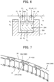
- FIG. 8 A second embodiment to which the present invention is applied is explained by using FIG. 8 . Note that portions in the present embodiment that are equivalent to their counterparts in the first embodiment are given the same reference characters, and explanations thereof are omitted as appropriate.
- FIG. 8 is a perspective view depicting the structure of a main portion of a tip seal in the present embodiment.
- the tip seal 29A according to the present embodiment has the groove 36A similarly to the first embodiment.
- the tip seal 29A according to the present embodiment has a communication hole 38A that does not have an opening on the sliding surface 30.
- the communication hole 38A establishes communication between the inside of the groove 36A and the working chamber S H on the inner side in the wrap width direction.
- the communication hole 38A is shorter than the groove 36A in the seal extension direction.
- the tip seal 29B according to the present embodiment has the groove 36B similarly to the first embodiment.
- the tip seal 29B according to the present embodiment has a communication hole 38B that does not have an opening on the sliding surface 30.
- the communication hole 38B establishes communication between the inside of the groove 36B and the working chamber S H on the inner side in the wrap width direction.
- the communication hole 38B is shorter than the groove 36B in the seal extension direction.
- the tip seal 29A according to the present embodiment also, similarly to the first embodiment, it is possible to suppress local wear while ensuring the sealability.
- the surface pressure of the sliding surface 30 decreases as compared to the first or second conventional technology mentioned above not only at cross sectional positions having the groove 36A, but not having the communication hole 38A, but also at a cross sectional position having the groove 36A and the communication hole 38A. Accordingly, it is possible to further suppress local wear.
- the advantages mentioned above can be attained about the tip seal 29B according to the present embodiment also.
- the communication hole 38A is shorter than the groove 36A in the seal extension direction, and the communication hole 38B is shorter than the groove 36B in the seal extension direction in the case of the example explained in the second embodiment, this is not the sole example.
- the communication hole 38A may have the same length as the groove 36A in the seal extension direction or may be longer than the groove 36A.
- the communication hole 38B may have the same length as the groove 36B in the seal extension direction or may be longer than the groove 36B. In this case also, advantages similar to those described above can be attained.
- each of the tip seals 29A and 29B has one set of a groove and a communication hole in the case of the example explained in the second embodiment, this is not the sole example.
- each of the tip seals 29A and 29B may have a plurality of sets of grooves and communication holes as long as they are in a range of the involute angle of the wrap where the differential pressure (P H -P L ) between the working chamber S H and the working chamber S L is equal to or higher than 0.1 MPa (i.e. where relative positions are 0.10 to 0.33).
- each of the tip seals 29A and 29B has a groove and a communication groove or communication hole in the cases of the examples explained in the first and second embodiments, these are not the sole examples. Only one of the tip seals 29A and 29B may have a groove and a communication groove or communication hole.
- both the wrap 16 of the fixed scroll 11 and the wrap 21 of the orbiting scroll 12 have seal grooves formed thereon, and tip seals are inserted into the seal grooves in the cases of the examples explained in the first and second embodiments, these are not the sole examples.
- Only one of the wrap 16 of the fixed scroll 11 and the wrap 21 of the orbiting scroll 12 may have a seal groove formed thereon, and a tip seal may be inserted into the seal groove. Then, the tip seal may have a groove and a communication groove or communication hole.
- scroll type compressor is an application subject of the present invention in the examples explained thus far, these are not the sole examples. That is, the present invention may be applied to another scroll type gas machine (specifically, a scroll type vacuum pump, etc.).
- a scroll type vacuum pump specifically, a scroll type vacuum pump, etc.
Landscapes
- Engineering & Computer Science (AREA)
- Mechanical Engineering (AREA)
- General Engineering & Computer Science (AREA)
- Rotary Pumps (AREA)
Abstract
Description
- The present invention relates to a scroll type gas machine such as a scroll type compressor or a scroll type vacuum pump.
-
Patent Document 1 discloses a scroll type compressor. The scroll type compressor includes a fixed scroll, an orbiting scroll, and a drive shaft. The fixed scroll has an mirror plate and a helical wrap provided upright on the mirror plate. The orbiting scroll has a mirror plate and a helical wrap provided upright on the mirror plate. Rotation of the drive shaft causes the orbiting scroll to orbit relative to the fixed scroll. - A plurality of working chambers are formed between the wrap of the fixed scroll and the wrap of the orbiting scroll. Each working chamber shifts from the outer side to the inner side in the wrap extension direction along with an orbiting motion of the orbiting scroll, and sequentially performs an intake process, a compression process, and a discharge process.
- A helical seal groove is formed on the tip side of the wrap of the orbiting scroll, a helical tip seal is inserted into the seal groove, and the sliding surface of the tip seal contacts the mirror plate of the fixed scroll. Similarly, a helical seal groove is formed on the tip side of the wrap of the fixed scroll, a helical tip seal is inserted into the seal groove, and the sliding surface of the tip seal contacts the mirror plate of the orbiting scroll. Thereby, the sealability of the working chambers is enhanced.
- Each tip seal in
Patent Document 1 has a plurality of recesses formed by cutting off corner portions on one side, in the seal width direction, of the sliding surface mentioned before. The shape of the recess as seen in a direction perpendicular to the sliding surface of the tip seal is a semi-cylindrical shape surrounded by an arc and a straight line or a rectangular shape. The recesses can reduce the area size of the sliding surface, and reduce the friction on the sliding surface. - Patent Document 1:
JP-2018-128014-A - Although the friction on the sliding surface of a tip seal is reduced by forming the recesses described in
Patent Document 1 on the sliding surface, the surface pressure of the sliding surface does not change. Details thereof are explained. - First, a case where the recesses described in
Patent Document 1 are not formed on the sliding surface of a tip seal is explained as a first conventional technology by usingFIG. 10. FIG. 10 is a wrap widthwise cross sectional view depicting the structure of a tip seal in the first conventional technology. - As depicted in
FIG. 10 , a working chamber SH on the inner side in the wrap width direction (the left side inFIG. 10 ) and a working chamber SL on the outer side in the wrap width direction (the right side inFIG. 10 ) are adjacent to each other with awrap 1 of an orbiting scroll interposed therebetween. Aseal groove 2 is formed on the tip side (the upper side inFIG. 10 ) of thewrap 1, and atip seal 3 is inserted into theseal groove 2. Thetip seal 3 has asliding surface 4, aninner surface 5, anouter surface 6, and abottom surface 7. Due to an effect of the pressure of gas in the working chamber SH on the high pressure side, a gap R1 between theinner surface 5 of thetip seal 3 and the inner surface of theseal groove 2, and a gap R2 between thebottom surface 7 of thetip seal 3 and the bottom surface of theseal groove 2 are formed. That is, part of the gas in the working chamber SH flows into the gaps R1 and R2, and a pressure PH thereof acts on thebottom surface 7 of thetip seal 3. On the other hand, the average pressure that acts on thesliding surface 4 of thetip seal 3 is the average value of the pressure PH of the gas in the working chamber SH and a pressure PL of gas in the working chamber SL. Accordingly, if the width of thetip seal 3 is defined as W, a surface pressure P1 of the sliding surface of thetip seal 3 in a direction (the upward direction inFIG. 10 ) pressing to amirror plate 8 of the fixed scroll is represented by the following Formula (1).
[Equation 1]
- Next, a case where the recesses described in
Patent Document 1 are formed on the sliding surface of a tip seal is explained as a second conventional technology by usingFIG. 11. FIG. 11 is a wrap widthwise cross sectional view depicting the structure of a tip seal in the second conventional technology. Note that portions equivalent to their counterparts in the first conventional technology are given the same reference characters, and explanations thereof are omitted as appropriate. - The
tip seal 3 has arecess 9 formed by cutting off a corner portion on the inner side (the left side inFIG. 11 ) of thesliding surface 4 in the seal width direction. Part of the gas in the working chamber SH flows into therecess 9, and the pressure PH acts on the bottom surface of therecess 9. Accordingly, if the width of therecess 9 is defined as (2/3)W, a surface pressure P2 of thesliding surface 4 of thetip seal 3 in a direction (the upward direction inFIG. 11 ) pressing to themirror plate 8 of the fixed scroll is represented by the following Formula (2).
[Equation 2]
- As is apparent from Formulae (1) and (2) described above, the surface pressure of the
sliding surface 4 of thetip seal 3 does not change in the first conventional technology and the second conventional technology. Accordingly, there is room for improvement in terms of reduction of the surface pressure of the slidingsurface 4 of thetip seal 3, and reduction of the amount of wear of thetip seal 3. - In addition, as is apparent from Formulae (1) and (2) described above, the surface pressure of the
sliding surface 4 of thetip seal 3 is proportional to the differential pressure (PH-PL) between the working chamber SH on the inner side in the wrap width direction and the working chamber SL on the outer side in the wrap width direction. As depicted inFIG. 12 , the differential pressure (PH-PL) changes according to the involute angle (winding angle) of the wrap. If an explanation is given by using the specific example depicted inFIG. 12 , the involute angle of the wrap at the inner end (an end at which the winding starts) of the wrap is 3.5 rad, and the involute angle of the wrap at the outer end (an end at which the winding ends) of the wrap is 29.3 rad. The differential pressure (PH-PL) is equal to or higher than 0.1 MPa in a range of the involute angle of the wrap from 6 to 12 rad, and the differential pressure (PH-PL) is lower than 0.1 MPa outside the range. If a relative position is defined such that the involute angle of the wrap at the inner end of the wrap is converted into 0 and the involute angle of the wrap at the outer end of the wrap is converted into 1, the differential pressure (PH-PL) is equal to or higher than 0.1 MPa in a range where the relative position is 0.10 to 0.33, and the differential pressure (PH-PL) is lower than 0.1 MPa outside the range. - In the first or second conventional technology, in a range of the involute angle of the wrap where the differential pressure (PH-PL) is equal to or higher than 0.1 MPa, the surface pressure of the sliding surface of the tip seal increases also. As a result, as depicted in
FIG. 13 , in the range of the involute angle of the wrap mentioned before, the amount of wear of the tip seal increases also. Accordingly, if the involute angle of the wrap is in the range mentioned before, preferably, the surface pressure of the sliding surface of the tip seal is reduced to suppress wear. - The present invention has been made in view of the matter described above, and one of objects thereof is to suppress wear of a tip seal.
- Configurations described in Claims are applied in order to solve the problem described above. The present invention includes a plurality of means for solving the problem described above, and one example thereof is a scroll type gas machine including: a fixed scroll having a mirror plate and a helical wrap provided upright on the mirror plate; an orbiting scroll having a mirror plate and a helical wrap provided upright on the mirror plate; a drive shaft that causes the orbiting scroll to orbit relative to the fixed scroll; and a helical tip seal inserted into a seal groove formed at least in one of the wrap of the fixed scroll and the wrap of the orbiting scroll, a plurality of working chambers being formed between the wrap of the fixed scroll and the wrap of the orbiting scroll, in which the tip seal has: a groove that has an opening at a central portion in a seal width direction on a sliding surface of the tip seal, and a communication hole that establishes communication between an inside of the groove and a working chamber on an inner side in a wrap width direction, the groove is provided in a range where a differential pressure is equal to or higher than 0.1 MPa between the working chamber on the inner side in the wrap width direction and a working chamber on an outer side in the wrap width direction, the working chambers being adjacent to each other with the wrap interposed therebetween, and the communication hole is shorter than the groove in a seal extension direction.
- According to the present invention, it is possible to suppress wear of a tip seal.
- Note that problems, configurations, and advantages other than those described above will become clear from the following explanation.
-
-
FIG. 1 is an axial cross sectional view depicting the structure of a scroll type compressor in a first embodiment to which the present invention is applied. -
FIG. 2 is a radial cross sectional view in the direction of arrows II-II inFIG. 1 . -
FIG. 3 is an exploded perspective view depicting the structures of an orbiting scroll and a tip seal in the first embodiment to which the present invention is applied. -
FIG. 4 is a perspective view depicting the structure of part of the tip seal corresponding to a portion IV inFIG. 3 . -
FIG. 5 is a perspective view depicting the structure of a main portion of a tip seal corresponding to a portion V inFIG. 3 . -
FIG. 6 is a wrap widthwise cross sectional view corresponding to a view in the direction of arrows VI-VI inFIG. 5 . -
FIG. 7 is a perspective view depicting the structure of a main portion of a tip seal in a first modification example to which the present invention is applied. -
FIG. 8 is a perspective view depicting the structure of a main portion of a tip seal in a second embodiment to which the present invention is applied. -
FIG. 9 is a perspective view depicting the structure of a main portion of a tip seal in a second modification example to which the present invention is applied. -
FIG. 10 is a wrap widthwise cross sectional view depicting the structure of a tip seal in a first conventional technology. -
FIG. 11 is a wrap widthwise cross sectional view depicting the structure of a tip seal in a second conventional technology. -
FIG. 12 is a figure depicting the distribution of differential pressure between a working chamber on the inner side in the wrap width direction and a working chamber on the outer side in the wrap width direction which are adjacent to each other with a wrap interposed therebetween. -
FIG. 13 is a figure depicting the distribution of the amount of wear of the tip seal in the first or second conventional technology. - A first embodiment to which the present invention is applied is explained with reference to the figures.
-
FIG. 1 is an axial cross sectional view depicting the structure of a scroll type compressor in the present embodiment.FIG. 2 is a radial cross sectional view in the direction of arrows II-II inFIG. 1 (n.b. a central portion in the radial direction is depicted, but an outer portion is not depicted).FIG. 3 is an exploded perspective view depicting the structures of an orbiting scroll and a tip seal in the present embodiment. - A scroll type compressor according to the present embodiment is, for example, an oil-free type scroll compressor (specifically, a compressor in which working chambers are operated in a state free of oil supply), and includes a
casing 10, a fixedscroll 11, an orbitingscroll 12, and adrive shaft 13. The fixedscroll 11 is coupled to the opening side of thecasing 10. The orbitingscroll 12 is housed in thecasing 10. Thedrive shaft 13 is rotatably supported by a bearing 14 in thecasing 10. - For example, the fixed
scroll 11 is formed of an aluminum alloy or the like, and has: an approximatelycircular mirror plate 15; ahelical wrap 16 provided upright on one surface side (the right side inFIG. 1 ) of themirror plate 15 facing the orbitingscroll 12; and a coolingfin 17 provided upright on the other surface side (the left side inFIG. 1 ) of themirror plate 15. Anintake flow path 18 is formed on the outer-circumference side of themirror plate 15, and adischarge flow path 19 is formed at a central portion of themirror plate 15. - The orbiting
scroll 12 is formed of an aluminum alloy or the like, and has: an approximatelycircular mirror plate 20; ahelical wrap 21 provided upright on one surface side (the left side inFIG. 1 ) of themirror plate 20 facing the fixedscroll 11; a coolingfin 22 provided upright on the other surface side of the mirror plate 20 (the right side inFIG. 1 ); and aback plate 23 provided on the tip side (the right side inFIG. 1 ) of the coolingfin 22. - The
drive shaft 13 extends in the horizontal direction (in the leftward/rightward direction inFIG. 1 ), and one end side thereof (the left side inFIG. 1 ) is provided with acrank portion 24. Thecrank portion 24 is eccentric from a center O of thedrive shaft 13, and is connected to a boss portion of theback plate 23 of the orbitingscroll 12 via aslewing bearing 25. - The other end side (the right side in
FIG. 1 ) of thedrive shaft 13 protrudes to the outside of thecasing 10, and is provided with apulley 26. A belt (not depicted) is wrapped around a pulley (not depicted) provided to a rotation shaft (not depicted) of an electric motor and thepulley 26. Thereby, rotational force of the electric motor is transferred to rotate thedrive shaft 13, and the orbitingscroll 12 orbits relative to the fixedscroll 11. - An
autorotation prevention mechanism 27 for preventing autorotation of the orbitingscroll 12 is provided between the orbitingscroll 12 and thecasing 10. Theautorotation prevention mechanism 27 includes: a plurality of auxiliary crank shafts that are arranged spaced apart from each other in the circumferential direction of thedrive shaft 13; a plurality of bearings that are provided to theback plate 23 of the orbitingscroll 12, and support one end side of the plurality of auxiliary crank shafts; and a plurality of bearings that are provided to thecasing 10, and support the other end side of the plurality of auxiliary crank shafts. - A plurality of working chambers S are formed between the
wrap 16 of the fixedscroll 11 and thewrap 21 of the orbitingscroll 12. Each working chamber S shifts from the outer side to the inner side in the wrap extension direction (counterclockwise inFIG. 2 ) along with an orbiting motion of the orbitingscroll 12, and sequentially performs an intake process, a compression process, and a discharge process. A working chamber S at the intake process takes in air (gas) via theintake flow path 18. A working chamber S at the compression process compresses air. A working chamber S at the discharge process discharges compressed air (compressed gas) via thedischarge flow path 19. - A
helical seal groove 28A is formed on the tip side (the left side inFIG. 1 , and the upper side inFIG. 3 ) of thewrap 21 of the orbitingscroll 12, ahelical tip seal 29A is inserted into theseal groove 28A, and the sliding surface of thetip seal 29A contacts themirror plate 15 of the fixedscroll 11. Similarly, ahelical seal groove 28B is formed on the tip side (the right side inFIG. 1 ) of thewrap 16 of the fixedscroll 11, ahelical tip seal 29B is inserted into theseal groove 28B, and the sliding surface of thetip seal 29B contacts themirror plate 20 of the orbitingscroll 12. Thereby, the sealability of the working chambers S is enhanced. Note that whereas thetip seal - For example, the
tip seal 29A is formed of an elastic resin, and has a slidingsurface 30, aninner surface 31, anouter surface 32, and abottom surface 33. In addition, thetip seal 29A has: a plurality ofinner lips 34 that are arranged on theinner surface 31 at predetermined intervals in the seal extension direction; and a plurality ofbottom lips 35 that are arranged on thebottom surface 33 at predetermined intervals in the seal extension direction. Theinner lips 34 are utilized for partitioning, in the seal extension direction, a gap R1 (seeFIG. 6 mentioned later) between theinner surface 31 of thetip seal 29A and the inner surface of theseal groove 28A when the gap R1 is formed. Thebottom lips 35 are utilized for partitioning, in the seal extension direction, a gap R2 (seeFIG. 6 mentioned later) between thebottom surface 33 of thetip seal 29A and the bottom surface of theseal groove 28A when the gap R2 is formed. - As a feature of the present embodiment, the
tip seal 29A has: agroove 36A that has an opening at a central portion of the slidingsurface 30 in the seal width direction; and acommunication groove 37A (communication hole) that establishes communication between the inside of thegroove 36A and a working chamber SH (seeFIG. 6 mentioned later) on the inner side in the wrap width direction. Thecommunication groove 37A has an opening on the slidingsurface 30. - The
groove 36A is provided in a range of the involute angle of thewrap 21 of the orbitingscroll 12, where a differential pressure (PH-PL) between the working chamber SH on the inner side in the wrap width direction and the working chamber SL on the outer side in the wrap width direction which are adjacent to each other with thewrap 21 interposed therebetween (seeFIG. 6 mentioned later) is equal to or higher than 0.1 MPa, and additionally, thegroove 36A is not provided outside the range. In particular, in the present embodiment, thegroove 36A is provided at an involute angle of thewrap 21 where the differential pressure (PH-PL) mentioned before is the highest. Thecommunication groove 37A is shorter than thegroove 36A in the seal extension direction. - Note that if an explanation is given by using the specific example depicted in
FIG. 12 mentioned above, the involute angle of thewrap 21 at the inner end (an end at which the winding starts) of thewrap 21 of the orbitingscroll 12 is 3.5 rad, and the involute angle of thewrap 21 at the outer end (an end at which the winding ends) of thewrap 21 is 29.3 rad. The differential pressure (PH-PL) mentioned before is equal to or higher than 0.1 MPa in the range of the involute angle of thewrap 21 from 6 to 12 rad, and the differential pressure (PH-PL) mentioned before is lower than 0.1 MPa outside the range. At a position where the involute angle of thewrap 21 is 9.6 rad, the differential pressure (PH-PL) mentioned before is the highest. If a relative position is defined such that the involute angle of thewrap 21 at the inner end of thewrap 21 is converted into 0 and the involute angle of thewrap 21 at the outer end of thewrap 21 is converted into 1, the differential pressure (PH-PL) mentioned before is equal to or higher than 0.1 MPa in a range where the relative position is 0.10 to 0.33, and the differential pressure (PH-PL) mentioned before is lower than 0.1 MPa outside the range. - Similarly to the
tip seal 29A, for example, thetip seal 29B is formed of an elastic resin, and has a slidingsurface 30, aninner surface 31, anouter surface 32, and abottom surface 33. In addition, similarly to tipseal 29A, thetip seal 29B has: a plurality ofinner lips 34 that are arranged on theinner surface 31 at predetermined intervals in the seal extension direction; and a plurality ofbottom lips 35 that are arranged on thebottom surface 33 at predetermined intervals in the seal extension direction. Theinner lips 34 are utilized for partitioning, in the seal extension direction, a gap between theinner surface 31 of thetip seal 29B and the inner surface of theseal groove 28B when the gap is formed. Thebottom lips 35 are utilized for partitioning, in the seal extension direction, a gap between thebottom surface 33 of thetip seal 29B and the bottom surface of theseal groove 28B when the gap is formed. - As a feature of the present embodiment, similarly to the
tip seal 29A, thetip seal 29B has: agroove 36B that has an opening at a central portion of the slidingsurface 30 in the seal width direction; and acommunication groove 37B (communication hole) that establishes communication between the inside of thegroove 36B and the working chamber SH on the inner side in the wrap width direction. Thecommunication groove 37B has an opening on the slidingsurface 30. - The
groove 36B is provided in a range of the involute angle of thewrap 16 of the fixedscroll 11, where a differential pressure (PH-PL) between the working chamber SH on the inner side in the wrap width direction and the working chamber SL on the outer side in the wrap width direction which are adjacent to each other with thewrap 16 interposed therebetween is equal to or higher than 0.1 MPa, and additionally, thegroove 36B is not provided outside the range. In particular, in the present embodiment, thegroove 36B is provided at an involute angle of thewrap 16 at which the differential pressure (PH-PL) mentioned before is the highest. Thecommunication groove 37B is shorter than thegroove 36B in the seal extension direction. - Note that if an explanation is given by using the specific example depicted in
FIG. 12 mentioned above, the involute angle of thewrap 16 at the inner end (an end at which the winding starts) of thewrap 16 of the fixedscroll 11 is 3.5 rad, and the involute angle of thewrap 16 at the outer end (an end at which the winding ends) of thewrap 16 is 29.3 rad. The differential pressure (PH-PL) mentioned before is equal to or higher than 0.1 MPa in the range of the involute angle of thewrap 16 from 6 to 12 rad, and the differential pressure (PH-PL) mentioned before is lower than 0.1 MPa outside the range. At a position where the involute angle of thewrap 16 is 9.6 rad, the differential pressure (PH-PL) mentioned before is the highest. If a relative position is defined such that the involute angle of thewrap 16 at the inner end of thewrap 16 is converted into 0, and the involute angle of thewrap 16 at the outer end of thewrap 16 is converted into 1, the differential pressure (PH-PL) mentioned before is equal to or higher than 0.1 MPa in a range where the relative position is 0.10 to 0.33, and the differential pressure (PH-PL) mentioned before is lower than 0.1 MPa outside the range. - Next, effects and advantages of the present embodiment are explained.
- At a cross sectional position having the
groove 36A and thecommunication groove 37A of thetip seal 29A according to the present embodiment, the surface pressure of the slidingsurface 30 is not different from the surface pressure in the first or second conventional technology mentioned above. However, at cross sectional positions having thegroove 36A, but not having thecommunication groove 37A, the surface pressure of the slidingsurface 30 decreases. Details thereof are explained by usingFIG. 6. FIG. 6 is a cross sectional view in the direction of arrows VI-VI inFIG. 5 . - As depicted in
FIG. 6 , the working chamber SH on the inner side in the wrap width direction (the left side inFIG. 6 ) and the working chamber SL on the outer side in the wrap width direction (the right side inFIG. 6 ) are adjacent to each other with thewrap 21 of the orbitingscroll 12 interposed therebetween. Due to an effect of the pressure of the gas in the high-pressure-side working chamber SH, the gap R1 between theinner surface 31 of thetip seal 29A and the inner surface of theseal groove 28A of thewrap 21, and the gap R2 between thebottom surface 33 of thetip seal 29A and the bottom surface of theseal groove 28A of thewrap 21 are formed. That is, part of the gas in the working chamber SH flows into the gaps R1 and R2, and the pressure PH thereof acts on thebottom surface 33 of thetip seal 29A. - On the other hand, part of the gas in the working chamber SH flows into the
groove 36A via thecommunication groove 37A of thetip seal 29A, and the pressure PH acts on the bottom surface of thegroove 36A. The average pressure that acts on portions positioned on the outer side of thegroove 36A in the seal width direction on the slidingsurface 30 of thetip seal 29A is the average value of the pressure PH of the gas in the working chamber SH and the pressure PL of the gas in the working chamber SL. The pressure that acts on portions positioned on the inner side of thegroove 36A in the seal width direction on the slidingsurface 30 of thetip seal 29A is the pressure PH of the gas in the working chamber SH. - Accordingly, if the full width of the
tip seal 29A is defined as W, and each of the widths of the groove and portions on the outer side and inner side in the seal width direction mentioned before is (1/3)W, a surface pressure P of the sliding surface of thetip seal 29A in a direction (the upward direction inFIG. 6 ) pressing to themirror plate 15 of the fixedscroll 11 is represented by the following Formula (3).
[Equation 3]
- As is apparent from Formulae (1) to (3) described above, at cross sectional positions having the
groove 36A, but not having thecommunication groove 37A of thetip seal 29A according to the present embodiment, the surface pressure of the slidingsurface 30 decreases as compared to the first or second conventional technology. - The
groove 36A is provided in a range of the involute angle of thewrap 21 where the differential pressure (PH-PL) between the working chamber SH and the working chamber SL is equal to or higher than 0.1 MPa. That is, thegroove 36A is provided in a range of the involute angle of thewrap 21 where the surface pressure of the slidingsurface 30 of thetip seal 29A is likely to increase. Accordingly, it is possible to suppress the local increase in surface pressures, and to suppress local wear. As a result, it is possible to increase the lifetime of thetip seal 29A. - In addition, the
groove 36A is not provided in a range of the involute angle of thewrap 21 where the differential pressure (PH-PL) between the working chamber SH and the working chamber SL is lower than 0.1 MPa. That is, thegroove 36A is not provided in a range of the involute angle of thewrap 21 where the surface pressure of the slidingsurface 30 of thetip seal 29A decreases. Accordingly, the sealability can be ensured without accompanying a reduction of the surface pressure more than necessary. - Similarly to the
tip seal 29A, the advantages mentioned above can be attained about thetip seal 29B according to the present embodiment also. - Note that whereas each of the tip seals 29A and 29B has one set of a groove and a communication groove in the case of the example explained in the first embodiment, this is not the sole example. For example, as depicted in
FIG. 7 , each of the tip seals 29A and 29B may have a plurality of sets of grooves and communication grooves as long as they are in a range of the involute angle of the wrap where the differential pressure (PH-PL) between the working chamber SH and the working chamber SL is equal to or higher than 0.1 MPa (i.e. where the relative position is 0.10 to 0.33). - A second embodiment to which the present invention is applied is explained by using
FIG. 8 . Note that portions in the present embodiment that are equivalent to their counterparts in the first embodiment are given the same reference characters, and explanations thereof are omitted as appropriate. -
FIG. 8 is a perspective view depicting the structure of a main portion of a tip seal in the present embodiment. - The
tip seal 29A according to the present embodiment has thegroove 36A similarly to the first embodiment. In addition, instead of thecommunication groove 37A, thetip seal 29A according to the present embodiment has acommunication hole 38A that does not have an opening on the slidingsurface 30. Similarly to thecommunication groove 37A, thecommunication hole 38A establishes communication between the inside of thegroove 36A and the working chamber SH on the inner side in the wrap width direction. In addition, similarly to thecommunication groove 37A, thecommunication hole 38A is shorter than thegroove 36A in the seal extension direction. - The
tip seal 29B according to the present embodiment has thegroove 36B similarly to the first embodiment. In addition, instead of thecommunication groove 37B, thetip seal 29B according to the present embodiment has acommunication hole 38B that does not have an opening on the slidingsurface 30. Similarly to thecommunication groove 37B, thecommunication hole 38B establishes communication between the inside of thegroove 36B and the working chamber SH on the inner side in the wrap width direction. In addition, similarly to thecommunication groove 37B, thecommunication hole 38B is shorter than thegroove 36B in the seal extension direction. - About the
tip seal 29A according to the present embodiment also, similarly to the first embodiment, it is possible to suppress local wear while ensuring the sealability. In addition, about thetip seal 29A according to the present embodiment, the surface pressure of the slidingsurface 30 decreases as compared to the first or second conventional technology mentioned above not only at cross sectional positions having thegroove 36A, but not having thecommunication hole 38A, but also at a cross sectional position having thegroove 36A and thecommunication hole 38A. Accordingly, it is possible to further suppress local wear. - Similarly to the
tip seal 29A, the advantages mentioned above can be attained about thetip seal 29B according to the present embodiment also. - Note that whereas the
communication hole 38A is shorter than thegroove 36A in the seal extension direction, and thecommunication hole 38B is shorter than thegroove 36B in the seal extension direction in the case of the example explained in the second embodiment, this is not the sole example. Thecommunication hole 38A may have the same length as thegroove 36A in the seal extension direction or may be longer than thegroove 36A. Thecommunication hole 38B may have the same length as thegroove 36B in the seal extension direction or may be longer than thegroove 36B. In this case also, advantages similar to those described above can be attained. - In addition, whereas each of the tip seals 29A and 29B has one set of a groove and a communication hole in the case of the example explained in the second embodiment, this is not the sole example. For example, as depicted in
FIG. 9 , each of the tip seals 29A and 29B may have a plurality of sets of grooves and communication holes as long as they are in a range of the involute angle of the wrap where the differential pressure (PH-PL) between the working chamber SH and the working chamber SL is equal to or higher than 0.1 MPa (i.e. where relative positions are 0.10 to 0.33). - In addition, whereas each of the tip seals 29A and 29B has a groove and a communication groove or communication hole in the cases of the examples explained in the first and second embodiments, these are not the sole examples. Only one of the tip seals 29A and 29B may have a groove and a communication groove or communication hole.
- In addition, both the
wrap 16 of the fixedscroll 11 and thewrap 21 of the orbitingscroll 12 have seal grooves formed thereon, and tip seals are inserted into the seal grooves in the cases of the examples explained in the first and second embodiments, these are not the sole examples. Only one of thewrap 16 of the fixedscroll 11 and thewrap 21 of the orbitingscroll 12 may have a seal groove formed thereon, and a tip seal may be inserted into the seal groove. Then, the tip seal may have a groove and a communication groove or communication hole. - Note that whereas the scroll type compressor is an application subject of the present invention in the examples explained thus far, these are not the sole examples. That is, the present invention may be applied to another scroll type gas machine (specifically, a scroll type vacuum pump, etc.).
-
- 11: Fixed scroll
- 12: Orbiting scroll
- 13: Drive shaft
- 15: Mirror plate
- 16: Wrap
- 20: Mirror plate
- 21: Wrap
- 28A, 28B: Seal groove
- 29A, 29B: Tip seal
- 30: Sliding surface
- 36A, 36B: Groove
- 37A, 37B: Communication groove (communication hole)
- 38A, 38B: Communication hole
Claims (12)
- A scroll type gas machine comprising:a fixed scroll having a mirror plate and a helical wrap provided upright on the mirror plate;an orbiting scroll having a mirror plate and a helical wrap provided upright on the mirror plate;a drive shaft that causes the orbiting scroll to orbit relative to the fixed scroll; anda helical tip seal inserted into a seal groove formed at least in one of the wrap of the fixed scroll and the wrap of the orbiting scroll,a plurality of working chambers being formed between the wrap of the fixed scroll and the wrap of the orbiting scroll, whereinthe tip seal hasa groove that has an opening at a central portion in a seal width direction on a sliding surface of the tip seal, anda communication hole that establishes communication between an inside of the groove and a working chamber on an inner side in a wrap width direction,the groove is provided in a range where a differential pressure is equal to or higher than 0.1 MPa between the working chamber on the inner side in the wrap width direction and a working chamber on an outer side in the wrap width direction, the working chambers being adjacent to each other with the wrap interposed therebetween, andthe communication hole is shorter than the groove in a seal extension direction.
- The scroll type gas machine according to claim 1, wherein
the groove is not provided outside the range. - The scroll type gas machine according to claim 1, wherein
the groove is provided at an involute angle of the wrap at which the differential pressure between the working chamber on the inner side in the wrap width direction and the working chamber on the outer side in the wrap width direction, the working chambers being adjacent to each other with the wrap interposed therebetween, is a highest. - The scroll type gas machine according to claim 1, wherein
the communication hole is a communication groove that has an opening on the sliding surface of the tip seal. - The scroll type gas machine according to claim 1, wherein
the communication hole does not have an opening on the sliding surface of the tip seal. - The scroll type gas machine according to claim 1, wherein
the working chambers are operated in a state free of oil supply. - A scroll type gas machine comprising:a fixed scroll having a mirror plate and a helical wrap provided upright on the mirror plate;an orbiting scroll having a mirror plate and a helical wrap provided upright on the mirror plate;a drive shaft that causes the orbiting scroll to orbit relative to the fixed scroll; anda helical tip seal inserted into a seal groove formed at least in one of the wrap of the fixed scroll and the wrap of the orbiting scroll,a plurality of working chambers being formed between the wrap of the fixed scroll and the wrap of the orbiting scroll, whereinthe tip seal hasa groove that has an opening at a central portion in a seal width direction on a sliding surface of the tip seal, anda communication hole that establishes communication between an inside of the groove and a working chamber on an inner side in a wrap width direction,where a relative position is defined such that an involute angle of the wrap at an inner end of the wrap is converted into 0, and the involute angle of the wrap at an outer end of the wrap is converted into 1, the groove is provided in a range where the relative position is 0.10 to 0.33, andthe communication hole is shorter than the groove in a seal extension direction.
- The scroll type gas machine according to claim 7, wherein
the groove is not provided outside the range. - The scroll type gas machine according to claim 7, wherein
the groove is provided at an involute angle of the wrap at which the differential pressure between the working chamber on the inner side in the wrap width direction and a working chamber on an outer side in the wrap width direction, the working chambers being adjacent to each other with the wrap interposed therebetween, is a highest. - The scroll type gas machine according to claim 7, wherein
the communication hole is a communication groove that has an opening on the sliding surface of the tip seal. - The scroll type gas machine according to claim 7, wherein
the communication hole does not have an opening on the sliding surface of the tip seal. - The scroll type gas machine according to claim 7, wherein
the working chambers are operated in a state free of oil supply.
Applications Claiming Priority (1)
| Application Number | Priority Date | Filing Date | Title |
|---|---|---|---|
| PCT/JP2020/026864 WO2022009390A1 (en) | 2020-07-09 | 2020-07-09 | Scroll-type gas machine |
Publications (3)
| Publication Number | Publication Date |
|---|---|
| EP4180666A1 true EP4180666A1 (en) | 2023-05-17 |
| EP4180666A4 EP4180666A4 (en) | 2024-04-03 |
| EP4180666B1 EP4180666B1 (en) | 2025-09-10 |
Family
ID=79552332
Family Applications (1)
| Application Number | Title | Priority Date | Filing Date |
|---|---|---|---|
| EP20943980.1A Active EP4180666B1 (en) | 2020-07-09 | 2020-07-09 | Scroll-type gas machine |
Country Status (5)
| Country | Link |
|---|---|
| US (1) | US11971034B2 (en) |
| EP (1) | EP4180666B1 (en) |
| JP (1) | JP7329148B2 (en) |
| CN (1) | CN114867941B (en) |
| WO (1) | WO2022009390A1 (en) |
Families Citing this family (3)
| Publication number | Priority date | Publication date | Assignee | Title |
|---|---|---|---|---|
| KR102874193B1 (en) | 2020-03-10 | 2025-10-20 | 도쿄엘렉트론가부시키가이샤 | Long-wave infrared thermal sensors for integration into track systems |
| US11738363B2 (en) | 2021-06-07 | 2023-08-29 | Tokyo Electron Limited | Bath systems and methods thereof |
| GB202415730D0 (en) * | 2024-10-25 | 2024-12-11 | Kovacevic Petar | Multi-vane positive displacement device |
Family Cites Families (18)
| Publication number | Priority date | Publication date | Assignee | Title |
|---|---|---|---|---|
| JPH0388985A (en) * | 1989-08-31 | 1991-04-15 | Daikin Ind Ltd | Scroll type fluid machine |
| JP2859666B2 (en) * | 1989-11-30 | 1999-02-17 | アネスト岩田株式会社 | Scroll compressor |
| JPH06288361A (en) * | 1993-04-07 | 1994-10-11 | Hitachi Ltd | Scroll compressor |
| JPH07119657A (en) * | 1993-10-20 | 1995-05-09 | Tokico Ltd | Scroll type fluid machinery |
| JPH07229485A (en) * | 1994-02-18 | 1995-08-29 | Tokico Ltd | Scroll type fluid machine and method for manufacturing seal member for scroll type fluid machine |
| JPH11148471A (en) * | 1997-11-14 | 1999-06-02 | Hitachi Koki Co Ltd | Scroll type fluid machine |
| CA2325752A1 (en) | 2000-06-01 | 2001-12-01 | Michael V. Kazakis | Oiless rotary scroll air compressor tipseal assembly |
| JP2003065266A (en) * | 2001-08-30 | 2003-03-05 | Hokuetsu Kogyo Co Ltd | Oil-free scroll fluid machine |
| JP4892238B2 (en) | 2003-10-17 | 2012-03-07 | パナソニック株式会社 | Scroll compressor |
| GB2472776B (en) * | 2009-08-14 | 2015-12-02 | Edwards Ltd | Scroll pump with tip seal pockets |
| JP6008568B2 (en) * | 2012-05-07 | 2016-10-19 | アネスト岩田株式会社 | Scroll fluid machinery |
| GB201603333D0 (en) * | 2016-02-26 | 2016-04-13 | Edwards Ltd | Scroll pump tip sealing |
| WO2018147338A1 (en) * | 2017-02-07 | 2018-08-16 | Ntn株式会社 | Tip seal for scroll compressor |
| US11536269B2 (en) * | 2017-02-07 | 2022-12-27 | Ntn Corporation | Tip seal for scroll compressor |
| JP2019074025A (en) * | 2017-10-17 | 2019-05-16 | Ntn株式会社 | Tip seal for scroll compressor |
| JP7000180B2 (en) * | 2017-02-07 | 2022-01-19 | Ntn株式会社 | Tip seal for scroll compressor |
| JP6792072B2 (en) * | 2017-05-15 | 2020-11-25 | 株式会社日立産機システム | Scroll fluid machine |
| JP6386144B1 (en) * | 2017-08-18 | 2018-09-05 | 三菱重工サーマルシステムズ株式会社 | Scroll fluid machinery |
-
2020
- 2020-07-09 US US17/791,255 patent/US11971034B2/en active Active
- 2020-07-09 WO PCT/JP2020/026864 patent/WO2022009390A1/en not_active Ceased
- 2020-07-09 CN CN202080090883.3A patent/CN114867941B/en active Active
- 2020-07-09 JP JP2022534596A patent/JP7329148B2/en active Active
- 2020-07-09 EP EP20943980.1A patent/EP4180666B1/en active Active
Also Published As
| Publication number | Publication date |
|---|---|
| US11971034B2 (en) | 2024-04-30 |
| EP4180666A4 (en) | 2024-04-03 |
| JPWO2022009390A1 (en) | 2022-01-13 |
| CN114867941A (en) | 2022-08-05 |
| US20230033883A1 (en) | 2023-02-02 |
| JP7329148B2 (en) | 2023-08-17 |
| CN114867941B (en) | 2024-03-26 |
| EP4180666B1 (en) | 2025-09-10 |
| WO2022009390A1 (en) | 2022-01-13 |
Similar Documents
| Publication | Publication Date | Title |
|---|---|---|
| EP1260713B1 (en) | Scroll compressor with Oldham coupling | |
| JP5260608B2 (en) | Scroll compressor | |
| US5588820A (en) | Scroll compressor having an axial compliance pressure chamber | |
| US5127809A (en) | Scroll compressor with reinforcing ribs on the orbiting scroll | |
| US11971034B2 (en) | Scroll type fluid machine | |
| US20080304994A1 (en) | Scroll Fluid Machine | |
| JPH0571479A (en) | Non-circular revolution scroll for optimizing displacement in axial direction | |
| EP2484909B1 (en) | Scroll fluid machine | |
| US8092199B2 (en) | Scroll compressor including a plurality of shoulder sections | |
| JPH05248371A (en) | Scroll fluid machine and scroll compressor | |
| JPH09170571A (en) | Scroll compressor | |
| JP2705656B2 (en) | Scroll compressor | |
| JPH0842467A (en) | Scroll compressor | |
| JP2858903B2 (en) | Scroll compressor | |
| JPH11257259A (en) | Scroll fluid machine | |
| JPH09112450A (en) | Scroll compressor | |
| JPH04269301A (en) | Scroll fluid machine | |
| EP3444475B1 (en) | Scroll fluid machine | |
| JP2005163745A (en) | Scroll compressor | |
| US20250075700A1 (en) | Drive assemblies and compressors including the same | |
| EP1087141A2 (en) | Scroll-type compressor | |
| JPH0617675B2 (en) | Scroll fluid machinery | |
| JP2925654B2 (en) | Scroll compressor | |
| JP2858897B2 (en) | Scroll compressor | |
| JP2743877B2 (en) | Scroll compressor |
Legal Events
| Date | Code | Title | Description |
|---|---|---|---|
| STAA | Information on the status of an ep patent application or granted ep patent |
Free format text: STATUS: THE INTERNATIONAL PUBLICATION HAS BEEN MADE |
|
| PUAI | Public reference made under article 153(3) epc to a published international application that has entered the european phase |
Free format text: ORIGINAL CODE: 0009012 |
|
| STAA | Information on the status of an ep patent application or granted ep patent |
Free format text: STATUS: REQUEST FOR EXAMINATION WAS MADE |
|
| 17P | Request for examination filed |
Effective date: 20230209 |
|
| AK | Designated contracting states |
Kind code of ref document: A1 Designated state(s): AL AT BE BG CH CY CZ DE DK EE ES FI FR GB GR HR HU IE IS IT LI LT LU LV MC MK MT NL NO PL PT RO RS SE SI SK SM TR |
|
| DAV | Request for validation of the european patent (deleted) | ||
| DAX | Request for extension of the european patent (deleted) | ||
| REG | Reference to a national code |
Free format text: PREVIOUS MAIN CLASS: F04C0018020000 Ipc: F01C0019000000 Ref country code: DE Ref legal event code: R079 Ref document number: 602020058780 Country of ref document: DE |
|
| A4 | Supplementary search report drawn up and despatched |
Effective date: 20240229 |
|
| RIC1 | Information provided on ipc code assigned before grant |
Ipc: F04C 27/00 20060101ALI20240223BHEP Ipc: F04C 18/02 20060101ALI20240223BHEP Ipc: F01C 19/00 20060101AFI20240223BHEP |
|
| GRAP | Despatch of communication of intention to grant a patent |
Free format text: ORIGINAL CODE: EPIDOSNIGR1 |
|
| STAA | Information on the status of an ep patent application or granted ep patent |
Free format text: STATUS: GRANT OF PATENT IS INTENDED |
|
| RIC1 | Information provided on ipc code assigned before grant |
Ipc: F04C 27/00 20060101ALI20250203BHEP Ipc: F04C 18/02 20060101ALI20250203BHEP Ipc: F01C 19/00 20060101AFI20250203BHEP |
|
| INTG | Intention to grant announced |
Effective date: 20250228 |
|
| GRAS | Grant fee paid |
Free format text: ORIGINAL CODE: EPIDOSNIGR3 |
|
| GRAA | (expected) grant |
Free format text: ORIGINAL CODE: 0009210 |
|
| STAA | Information on the status of an ep patent application or granted ep patent |
Free format text: STATUS: THE PATENT HAS BEEN GRANTED |
|
| AK | Designated contracting states |
Kind code of ref document: B1 Designated state(s): AL AT BE BG CH CY CZ DE DK EE ES FI FR GB GR HR HU IE IS IT LI LT LU LV MC MK MT NL NO PL PT RO RS SE SI SK SM TR |
|
| REG | Reference to a national code |
Ref country code: GB Ref legal event code: FG4D |
|
| REG | Reference to a national code |
Ref country code: CH Ref legal event code: EP |
|
| REG | Reference to a national code |
Ref country code: DE Ref legal event code: R096 Ref document number: 602020058780 Country of ref document: DE |
|
| REG | Reference to a national code |
Ref country code: IE Ref legal event code: FG4D |
|
| PG25 | Lapsed in a contracting state [announced via postgrant information from national office to epo] |
Ref country code: NO Free format text: LAPSE BECAUSE OF FAILURE TO SUBMIT A TRANSLATION OF THE DESCRIPTION OR TO PAY THE FEE WITHIN THE PRESCRIBED TIME-LIMIT Effective date: 20251210 |
|
| REG | Reference to a national code |
Ref country code: LT Ref legal event code: MG9D |
|
| PG25 | Lapsed in a contracting state [announced via postgrant information from national office to epo] |
Ref country code: FI Free format text: LAPSE BECAUSE OF FAILURE TO SUBMIT A TRANSLATION OF THE DESCRIPTION OR TO PAY THE FEE WITHIN THE PRESCRIBED TIME-LIMIT Effective date: 20250910 |
|
| REG | Reference to a national code |
Ref country code: NL Ref legal event code: MP Effective date: 20250910 |
|
| PG25 | Lapsed in a contracting state [announced via postgrant information from national office to epo] |
Ref country code: HR Free format text: LAPSE BECAUSE OF FAILURE TO SUBMIT A TRANSLATION OF THE DESCRIPTION OR TO PAY THE FEE WITHIN THE PRESCRIBED TIME-LIMIT Effective date: 20250910 |
|
| PG25 | Lapsed in a contracting state [announced via postgrant information from national office to epo] |
Ref country code: GR Free format text: LAPSE BECAUSE OF FAILURE TO SUBMIT A TRANSLATION OF THE DESCRIPTION OR TO PAY THE FEE WITHIN THE PRESCRIBED TIME-LIMIT Effective date: 20251211 |
|
| PG25 | Lapsed in a contracting state [announced via postgrant information from national office to epo] |
Ref country code: SE Free format text: LAPSE BECAUSE OF FAILURE TO SUBMIT A TRANSLATION OF THE DESCRIPTION OR TO PAY THE FEE WITHIN THE PRESCRIBED TIME-LIMIT Effective date: 20250910 |
|
| PG25 | Lapsed in a contracting state [announced via postgrant information from national office to epo] |
Ref country code: LV Free format text: LAPSE BECAUSE OF FAILURE TO SUBMIT A TRANSLATION OF THE DESCRIPTION OR TO PAY THE FEE WITHIN THE PRESCRIBED TIME-LIMIT Effective date: 20250910 |
|
| PG25 | Lapsed in a contracting state [announced via postgrant information from national office to epo] |
Ref country code: PL Free format text: LAPSE BECAUSE OF FAILURE TO SUBMIT A TRANSLATION OF THE DESCRIPTION OR TO PAY THE FEE WITHIN THE PRESCRIBED TIME-LIMIT Effective date: 20250910 Ref country code: BG Free format text: LAPSE BECAUSE OF FAILURE TO SUBMIT A TRANSLATION OF THE DESCRIPTION OR TO PAY THE FEE WITHIN THE PRESCRIBED TIME-LIMIT Effective date: 20250910 |
|
| PG25 | Lapsed in a contracting state [announced via postgrant information from national office to epo] |
Ref country code: RS Free format text: LAPSE BECAUSE OF FAILURE TO SUBMIT A TRANSLATION OF THE DESCRIPTION OR TO PAY THE FEE WITHIN THE PRESCRIBED TIME-LIMIT Effective date: 20251210 |
|
| PG25 | Lapsed in a contracting state [announced via postgrant information from national office to epo] |
Ref country code: ES Free format text: LAPSE BECAUSE OF FAILURE TO SUBMIT A TRANSLATION OF THE DESCRIPTION OR TO PAY THE FEE WITHIN THE PRESCRIBED TIME-LIMIT Effective date: 20250910 |
|
| REG | Reference to a national code |
Ref country code: AT Ref legal event code: MK05 Ref document number: 1836080 Country of ref document: AT Kind code of ref document: T Effective date: 20250910 |
|
| PG25 | Lapsed in a contracting state [announced via postgrant information from national office to epo] |
Ref country code: NL Free format text: LAPSE BECAUSE OF FAILURE TO SUBMIT A TRANSLATION OF THE DESCRIPTION OR TO PAY THE FEE WITHIN THE PRESCRIBED TIME-LIMIT Effective date: 20250910 |
|
| PG25 | Lapsed in a contracting state [announced via postgrant information from national office to epo] |
Ref country code: SM Free format text: LAPSE BECAUSE OF FAILURE TO SUBMIT A TRANSLATION OF THE DESCRIPTION OR TO PAY THE FEE WITHIN THE PRESCRIBED TIME-LIMIT Effective date: 20250910 |
|
| PG25 | Lapsed in a contracting state [announced via postgrant information from national office to epo] |
Ref country code: AT Free format text: LAPSE BECAUSE OF FAILURE TO SUBMIT A TRANSLATION OF THE DESCRIPTION OR TO PAY THE FEE WITHIN THE PRESCRIBED TIME-LIMIT Effective date: 20250910 |
|
| PG25 | Lapsed in a contracting state [announced via postgrant information from national office to epo] |
Ref country code: IT Free format text: LAPSE BECAUSE OF FAILURE TO SUBMIT A TRANSLATION OF THE DESCRIPTION OR TO PAY THE FEE WITHIN THE PRESCRIBED TIME-LIMIT Effective date: 20250910 |
|
| PG25 | Lapsed in a contracting state [announced via postgrant information from national office to epo] |
Ref country code: IS Free format text: LAPSE BECAUSE OF FAILURE TO SUBMIT A TRANSLATION OF THE DESCRIPTION OR TO PAY THE FEE WITHIN THE PRESCRIBED TIME-LIMIT Effective date: 20260110 |
|
| PG25 | Lapsed in a contracting state [announced via postgrant information from national office to epo] |
Ref country code: CZ Free format text: LAPSE BECAUSE OF FAILURE TO SUBMIT A TRANSLATION OF THE DESCRIPTION OR TO PAY THE FEE WITHIN THE PRESCRIBED TIME-LIMIT Effective date: 20250910 Ref country code: PT Free format text: LAPSE BECAUSE OF FAILURE TO SUBMIT A TRANSLATION OF THE DESCRIPTION OR TO PAY THE FEE WITHIN THE PRESCRIBED TIME-LIMIT Effective date: 20260112 |
|
| PG25 | Lapsed in a contracting state [announced via postgrant information from national office to epo] |
Ref country code: EE Free format text: LAPSE BECAUSE OF FAILURE TO SUBMIT A TRANSLATION OF THE DESCRIPTION OR TO PAY THE FEE WITHIN THE PRESCRIBED TIME-LIMIT Effective date: 20250910 Ref country code: SK Free format text: LAPSE BECAUSE OF FAILURE TO SUBMIT A TRANSLATION OF THE DESCRIPTION OR TO PAY THE FEE WITHIN THE PRESCRIBED TIME-LIMIT Effective date: 20250910 |