EP4180586A1 - Work machine, program, and method for controlling work machine - Google Patents
Work machine, program, and method for controlling work machine Download PDFInfo
- Publication number
- EP4180586A1 EP4180586A1 EP21837915.4A EP21837915A EP4180586A1 EP 4180586 A1 EP4180586 A1 EP 4180586A1 EP 21837915 A EP21837915 A EP 21837915A EP 4180586 A1 EP4180586 A1 EP 4180586A1
- Authority
- EP
- European Patent Office
- Prior art keywords
- attachment
- information
- angle
- data
- work
- Prior art date
- Legal status (The legal status is an assumption and is not a legal conclusion. Google has not performed a legal analysis and makes no representation as to the accuracy of the status listed.)
- Pending
Links
Images



Classifications
-
- E—FIXED CONSTRUCTIONS
- E02—HYDRAULIC ENGINEERING; FOUNDATIONS; SOIL SHIFTING
- E02F—DREDGING; SOIL-SHIFTING
- E02F3/00—Dredgers; Soil-shifting machines
- E02F3/04—Dredgers; Soil-shifting machines mechanically-driven
- E02F3/96—Dredgers; Soil-shifting machines mechanically-driven with arrangements for alternate or simultaneous use of different digging elements
- E02F3/965—Dredgers; Soil-shifting machines mechanically-driven with arrangements for alternate or simultaneous use of different digging elements of metal-cutting or concrete-crushing implements
-
- E—FIXED CONSTRUCTIONS
- E02—HYDRAULIC ENGINEERING; FOUNDATIONS; SOIL SHIFTING
- E02F—DREDGING; SOIL-SHIFTING
- E02F3/00—Dredgers; Soil-shifting machines
- E02F3/04—Dredgers; Soil-shifting machines mechanically-driven
- E02F3/28—Dredgers; Soil-shifting machines mechanically-driven with digging tools mounted on a dipper- or bucket-arm, i.e. there is either one arm or a pair of arms, e.g. dippers, buckets
- E02F3/36—Component parts
- E02F3/42—Drives for dippers, buckets, dipper-arms or bucket-arms
- E02F3/43—Control of dipper or bucket position; Control of sequence of drive operations
- E02F3/435—Control of dipper or bucket position; Control of sequence of drive operations for dipper-arms, backhoes or the like
-
- E—FIXED CONSTRUCTIONS
- E02—HYDRAULIC ENGINEERING; FOUNDATIONS; SOIL SHIFTING
- E02F—DREDGING; SOIL-SHIFTING
- E02F3/00—Dredgers; Soil-shifting machines
- E02F3/04—Dredgers; Soil-shifting machines mechanically-driven
- E02F3/96—Dredgers; Soil-shifting machines mechanically-driven with arrangements for alternate or simultaneous use of different digging elements
- E02F3/963—Arrangements on backhoes for alternate use of different tools
-
- E—FIXED CONSTRUCTIONS
- E02—HYDRAULIC ENGINEERING; FOUNDATIONS; SOIL SHIFTING
- E02F—DREDGING; SOIL-SHIFTING
- E02F9/00—Component parts of dredgers or soil-shifting machines, not restricted to one of the kinds covered by groups E02F3/00 - E02F7/00
- E02F9/26—Indicating devices
- E02F9/264—Sensors and their calibration for indicating the position of the work tool
Definitions
- the present invention relates to a work machine such as a construction machine, a program, and a method for controlling a work machine, and particularly relates to a work machine that transmits attachment information from a communication device disposed at a replaceable attachment to a communication device disposed at a main body part, a program, and a method for controlling the work machine.
- a work machine has been put into practical use such as a construction machine including a main body part having a lower travelling body and an upper slewing body, and a work device to which a replaceable attachment is attached and which is attached to the main body part so as to be changeable in attitude.
- a construction machine including a main body part having a lower travelling body and an upper slewing body, and a work device to which a replaceable attachment is attached and which is attached to the main body part so as to be changeable in attitude.
- it is required to identify an attachment attached to a work device in real time for appropriate control of a work machine and appropriate management of an operation condition of the work machine.
- a two-dimensional bar code indicating attachment information is attached to an attachment.
- the attachment information is acquired by reading the two-dimensional bar code using a mobile terminal by a worker.
- the acquired attachment information is wirelessly transmitted from the mobile terminal to a control unit of the work machine.
- the control unit controls a maximum flow rate of hydraulic oil supplied to the attachment based on the received attachment information.
- a plurality of pieces of correlation data is stored in a storage unit in advance, the correlation data indicating a relationship between a cylinder speed of a hydraulic cylinder and an operation command value for operating the hydraulic cylinder according to a type of bucket.
- Type data indicating a type of bucket is acquired by an acquisition unit.
- a control unit selects one piece of the correlation data corresponding to the type data acquired by the acquisition unit from among the plurality of pieces of correlation data stored in the storage unit, and controls the operation command value based on the selected correlation data.
- Patent Literature 1 since it is necessary for a worker to get off the work machine and perform work of reading the two-dimensional bar code to acquire the attachment information, work efficiency is low.
- An object of the present invention is to obtain a work machine capable of efficiently and accurately acquiring attachment information of a replaceable attachment, a program, and a method for controlling the work machine.
- a work machine includes: a main body part; a work device to which a replaceable attachment is attached and which is attached to the main body part so as to be changeable in attitude; an angle detection means that detects a drive angle of the work device and outputs angle data; a first communication device disposed at the attachment; a second communication device disposed at the main body part; and a determination unit, in which the first communication device includes: an inertial sensor that detects a direction of the attachment with respect to a predetermined reference direction to output first direction data; and a transmitter that transmits attachment information including the first direction data as a radio signal, the second communication device includes a receiver that receives the attachment information transmitted from the transmitter, and the determination unit includes: a direction specifying unit that specifies a direction of the attachment with respect to the reference direction based on the angle data input from the angle detection means to output second direction data; and a difference/similarity determination unit that determines difference or similarity between a transmission source attachment of the attachment information and the attachment attached to the work
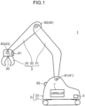
- FIG. 1 is a diagram schematically illustrating a configuration of a work machine 1 according to an embodiment of the present invention.
- the work machine 1 is a construction machine to which a nibbler is attached as a replaceable attachment 33. It is noted that the attachment is not limited to a nibbler, and another attachment 33 such as a bucket or a breaker may be attached.
- the work machine is not limited to a construction machine, and may be another work machine such as an agricultural machine or an industrial machine to which an arbitrary replaceable and attitude-changeable attachment is attached.
- the work machine 1 includes a crawler type lower travelling body 21, an upper slewing body 22 slewably disposed on the lower travelling body 21, and a work device 3 attached to the upper slewing body 22.
- the lower travelling body 21 and the upper slewing body 22 constitute a main body part 2 of the work machine 1.
- the work device 3 includes a boom 31 attached to the upper slewing body 22 so as to be raised and lowered, an arm 32 swingably attached to a distal end of the boom 31, and an attachment 33 swingably attached to a distal end of the arm 32.
- the work device 3 includes an actuator such as a boom cylinder that raises and lowers the boom 31 with respect to the upper slewing body 22, an actuator such as an arm cylinder that swings the arm 32 with respect to the boom 31, and an actuator such as an attachment cylinder that swings the attachment 33 with respect to the arm 32.
- a controller 7 that controls the entire work machine 1 is disposed inside the upper slewing body 22.
- An attitude of the work device 3 is changed by changing an angle (boom angle) of the boom 31 with respect to the upper slewing body 22, an angle (arm angle) of the arm 32 with respect to the boom 31, and an angle (attachment angle) of the attachment 33 with respect to the arm 32 by hydraulic control of the controller 7 according to lever operation by an operator of the work machine 1.
- the work machine 1 further includes angle sensors 41 to 43 each configured with a potentiometer, a rotary encoder, or the like.
- the angle sensor 41 detects a boom angle ⁇ 1 (see FIG. 9 ) by detecting a rotation angle of a rotation shaft 81 (also referred to as a "boom foot pin") coupling the upper slewing body 22 and the boom 31, and outputs boom angle data indicating the boom angle ⁇ 1.
- the angle sensor 42 (arm angle sensor) detects an arm angle ⁇ 2 (see FIG.
- the angle sensor 43 detects an attachment angle ⁇ 3 (see FIG. 9 ) by detecting a rotation angle of a rotation shaft 83 (also referred to as an "arm top pin”) coupling the arm 32 and the attachment 33, and outputs attachment angle data indicating the attachment angle ⁇ 3.
- the angle sensors 41 to 43 are connected to the controller 7 by wire, and the boom angle data, the arm angle data, and the attachment angle data are input from the angle sensors 41 to 43 to the controller 7, respectively.
- the work machine 1 further includes an inclination sensor 5 configured with an inertial sensor such as an acceleration sensor or a gyro sensor.
- the inclination sensor 5 is disposed in the upper slewing body 22.
- the inclination sensor 5 detects an inclination angle ⁇ 4 (see FIG. 9 ) of a slewing plane L1 of the upper slewing body 22 with respect to a horizontal direction X, and outputs inclination angle data indicating the inclination angle ⁇ 4.
- the inclination sensor 5 is connected to the controller 7 by wire, and the inclination angle data is input from the inclination sensor 5 to the controller 7.
- the work machine 1 includes a slave device 61 as a first communication device and a master device 62 as a second communication device.
- the slave device 61 and the master device 62 can wirelessly communicate with each other by an arbitrary communication system such as Wi-Fi, Bluetooth (registered trademark), or a low power wide area (LPWA).
- the slave device 61 is disposed at the attachment 33, and the master device 62 is disposed at the upper slewing body 22. In a case where there are a plurality of attachments 33, the slave device 61 is disposed for each of the plurality of attachments 33.
- the slave device 61 is disposed on a back surface 30 (a surface opposed to the upper slewing body 22) of the attachment 33
- the master device 62 is disposed on a front surface (a surface opposed to the attachment 33) of the upper slewing body 22.
- the master device 62 and the controller 7 can perform wired communication or wireless communication with each other by an arbitrary communication system such as a controller area network (CAN).
- CAN controller area network
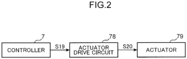
- FIG. 2 is a block diagram illustrating a configuration for operating the work device 3 in a simplified manner.
- the controller 7 controls an actuator drive circuit 78 by control information S19, and the actuator drive circuit 78 controls an actuator 79 by control information S20.
- the actuator 79 includes the above-described boom cylinder, arm cylinder, attachment cylinder, and the like.
- the actuator drive circuit 78 includes a hydraulic pump driven by an engine as a power source, a control valve for regulating a supply amount of hydraulic oil from the hydraulic pump to each actuator 79, an operation lever for generating a pilot pressure for controlling the control valve, and the like.
- the control valve is controlled by the pilot pressure varying according to an operation amount of the operation lever, and the hydraulic oil of a discharge amount according to the pilot pressure is supplied to the actuator 79, so that the actuator 79 is operated by a hydraulic pressure of the hydraulic oil.
- the work device 3 executes desired operation according to the lever operation of the operator.
- FIG. 3 is a view illustrating a part of the configuration of the work device 3.
- the attachment 33 is rotatably fixed to the distal end of the arm 32 by an arm top pin 83 that is detachable when the attachment 33 is replaced.
- One end of an idler link 89 is rotatably fixed to the arm 32 by an idler link pin 85.
- One end of an attachment link 90 is rotatably fixed to the attachment 33 by an attachment link pin 84 that is detachable when the attachment 33 is replaced.
- the other end of the idler link 89 and the other end of the attachment link 90 are rotatably fixed to a distal end of a rod 88 of an attachment cylinder 87 by an attachment rod pin 86.
- an extending direction of a straight line connecting the arm top pin 83 and the attachment link pin 84 is perpendicular to the back surface 30 of the attachment 33 at which the slave device 61 is disposed.
- FIG. 4 is a block diagram illustrating a configuration of the slave device 61.
- the slave device 61 includes an inertial sensor 611 such as an acceleration sensor or a gyro sensor, a signal processing unit 612, a nonvolatile storage unit 613 such as a ROM, a transmitter 614 for wireless communication, and a counter 615 that counts the number of clocks of a predetermined operation clock.
- the inertial sensor 611 detects an angle ⁇ 1 (see FIG. 9 ) of a principal surface normal line direction of the slave device 61 with respect to a predetermined reference direction, and outputs a signal S11 including first direction data D1 indicating the angle ⁇ 1.
- the predetermined reference direction is a vertically downward direction Y
- the principal surface normal line direction of the slave device 61 is equal to a direction in which a normal line H of the back surface 30 of the attachment 33 extends.
- the storage unit 613 stores control information S12 regarding the attachment 33 at which its own slave device 61 is disposed.
- the control information S12 includes, for example, type information, unique identification information, manufacturer information, control parameters, and the like of the attachment 33.
- the control parameters include pressure information (relief pressure, allowable upper limit value of in-cylinder pressure, etc.) of hydraulic oil supplied to the attachment 33, flow rate information (pump flow rate, pilot pressure, etc.) of the hydraulic oil supplied to the attachment 33, dimensional information (outer dimension, gravity center positional information, etc.) of the attachment, and the like.
- the signal processing unit 612 generates attachment information S13 including the first direction data D1 input from the inertial sensor 611 and the control information S12 read from the storage unit 613, and transfers the generated attachment information S13 to the transmitter 614.
- the signal processing unit 612 repeatedly executes generation processing and transfer processing of the attachment information S13 at a predetermined transmission time interval defined by the counter 615.
- the transmission time interval can be set to an arbitrary value within a range of several seconds to several minutes, for example.
- the transmitter 614 modulates the attachment information S13 input from the signal processing unit 612 to transmit attachment information S14 as a radio signal with a predetermined transmission signal strength.
- FIG. 5 is a flowchart illustrating an operation flow of the slave device 61.
- a drive power of the slave device 61 is supplied from a button battery or the like contained in the slave device 61.
- the counter 615 first clears a counter value in Step SP21.
- Step SP22 the counter 615 increments the counter value by counting the number of clocks of the predetermined operation clock.
- Step SP23 the signal processing unit 612 determines whether or not the counter value of the counter 615 has reached a predetermined set value (corresponding to the above described transmission time interval).
- Step SP23 NO
- the operations of Steps SP22 and SP23 are repeatedly executed.
- Step SP24 the signal processing unit 612 generates the attachment information S13 based on the first direction data D1 and the control information S12, and inputs the generated attachment information S13 to the transmitter 614.
- the attachment information S14 as the radio signal is transmitted from the transmitter 614.
- Step SP25 the signal processing unit 612 determines whether or not to stop power supply to the slave device 61 due to shortage of a remaining capacity of the button battery or the like.
- Step SP25 NO
- the operations after Step SP21 are repeatedly executed.
- Step SP25 the signal processing unit 612 ends the operation of each part of the slave device 61 to stop the power supply to the slave device 61.
- FIG. 6 is a block diagram illustrating a configuration of the master device 62. As illustrated in a connection relationship of FIG. 6 , the master device 62 includes a receiver 621 for wireless communication, a signal processing unit 622, and a transfer processing unit 623.
- the receiver 621 receives the attachment information S14 as the radio signal transmitted from the transmitter 614 of the slave device 61, and demodulates the attachment information S13.
- the receiver 621 generates attachment information S15 including an RSSI value indicating a received signal strength of the attachment information S14 by adding the RSSI value to the attachment information S13.
- the signal processing unit 622 performs error detection processing and error correction processing by an arbitrary algorithm on the attachment information S15 input from the receiver 621 to output attachment information S16 in which a code error accompanying the wireless communication is corrected.
- the transfer processing unit 623 transfers the attachment information S16 input from the signal processing unit 622 to the controller 7 according to a predetermined transfer condition.
- the transfer condition is, for example, transfer in a case where the type of the attachment is nibbler, and no transfer in other cases, or transfer in a case where a manufacturer of the attachment is an authorized manufacturer, and no transfer in other cases. Note that the transfer processing unit 623 may be omitted.
- FIG. 7 is a block diagram illustrating a configuration of the controller 7. As illustrated in a connection relationship of FIG. 7 , the controller 7 includes a determination unit 71 realized as a function of an information processing device such as a CPU, a control unit 72, and a nonvolatile storage unit 73 such as a ROM. The storage unit 73 stores a program 100.
- FIG. 8 is a block diagram illustrating a functional configuration of the determination unit 71.
- the information processing device reads the program 100 illustrated in FIG. 7 from the storage unit 73 and executes the program, whereby the determination unit 71 functions as a direction specifying unit 711 and a difference/similarity determination unit 712.
- the program 100 is a program for causing the information processing device mounted on the work machine 1 to function as the direction specifying unit 711 and the difference/similarity determination unit 712.
- the direction specifying unit 711 specifies a direction of the attachment 33 with respect to the reference direction (the vertically downward direction Y) based on angle data S17 (first to fourth angle data) input from the angle detection means (the angle sensors 41 to 43 and the inclination sensor 5), and outputs second direction data D2 indicating the direction.
- the direction of the attachment 33 is an angle ⁇ 2 (see FIG. 9 ) of the principal surface normal line direction of the slave device 61.
- FIG. 9 is a diagram illustrating a relationship among the boom angle ⁇ 1, the arm angle ⁇ 2, the attachment angle ⁇ 3, the inclination angle 04, and the angle ⁇ 2.
- the boom angle ⁇ 1 is an angle formed by the slewing plane L1 of the upper slewing body 22 and a straight line L2 passing through the boom foot pin 81 and the boom top pin 82.
- the arm angle ⁇ 2 is an angle formed by the straight line L2 and a straight line L3 passing through the arm foot pin 82 and the arm top pin 83.
- the attachment angle ⁇ 3 is an angle formed by the straight line L3 and a straight line L4 passing through the arm top pin 83 and the attachment link pin 84.
- the inclination angle ⁇ 4 is an angle formed by the horizontal direction X and the slewing plane L1 of the upper slewing body 22.
- the angle ⁇ 2 is an angle formed by the vertically downward direction Y and the straight line L4.
- the angle ⁇ 2 is expressed by the following Formula (1) using the boom angle ⁇ 1, the arm angle ⁇ 2, the attachment angle ⁇ 3, and the inclination angle ⁇ 4.
- ⁇ 2 ⁇ 3 + ⁇ 2 ⁇ ⁇ 1 + ⁇ 4 ⁇ 90
- the direction specifying unit 711 calculates the angle ⁇ 2 by performing the calculation of the Formula (1) based on the angle data S17 and outputs the second direction data D2 indicating the angle ⁇ 2.
- the difference/similarity determination unit 712 determines difference or similarity between an attachment of a transmission source of the attachment information S14 (hereinafter referred to as "transmission source attachment”) and the attachment attached to the work device 3 of the own machine (hereinafter referred to as "own machine attachment").
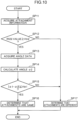
- FIG. 10 is a flowchart illustrating a processing flow of the determination unit 71.
- the difference/similarity determination unit 712 acquires the attachment information S16 from the master device 62.
- the attachment information S16 includes the first direction data D1, the control information S12, and the RSSI value.
- the difference/similarity determination unit 712 determines whether or not the RSSI value included in the attachment information S16 is equal to or greater than a predetermined threshold value Vth2 set in advance.
- the threshold value Vth2 is set such that an RSSI value when the attachment information S14 transmitted from the own machine attachment is received by the receiver 621 of the own machine is equal to or greater than the threshold value Vth2, and an RSSI value when the attachment information S14 transmitted from an attachment (hereinafter referred to as a "nearby attachment") attached to a work machine parked in the vicinity of the own machine is received by the receiver 621 of the own machine is less than the threshold value Vth2.
- Step SP17 the difference/similarity determination unit 712 determines that the transmission source attachment and the own machine attachment are different from each other, and ends the processing.
- Step SP12 When the RSSI value included in the attachment information S16 is equal to or greater than the threshold value Vth2 (Step SP12: YES), next, in Step SP13, the direction specifying unit 711 acquires the angle data S17 (boom angle data, arm angle data, attachment angle data, and inclination angle data) from the angle sensors 41 to 43 and the inclination sensor 5.
- the angle data S17 boost angle data, arm angle data, attachment angle data, and inclination angle data
- Step SP14 the direction specifying unit 711 calculates the angle ⁇ 2 by performing the calculation of the Formula (1) based on the angle data S17, and outputs the second direction data D2 indicating the angle ⁇ 2.
- the second direction data D2 is input to the difference/similarity determination unit 712.
- Step SP15 the difference/similarity determination unit 712 calculates an absolute value of a difference between the angle ⁇ 1 indicated by the first direction data D1 included in the attachment information S16 and the angle ⁇ 2 indicated by the second direction data D2 input from the direction specifying unit 711, and determines whether or not the value is equal to or less than a predetermined threshold value Vth1.
- Step SP17 the difference/similarity determination unit 712 determines that the transmission source attachment and the own machine attachment are different from each other, and ends the processing.
- Step SP16 the difference/similarity determination unit 712 determines that the transmission source attachment and the own machine attachment are the same, inputs the control information S12 included in the attachment information S16 to the control unit 72 as control information S18, and ends the processing.
- the control unit 72 updates the control information S19 for controlling the actuator drive circuit 78 with the control information S18 input from the determination unit 71.
- the control unit 72 updates a drive start pressure value of an electromagnetic relief valve based on hydraulic oil pressure information included in the control information S18.
- the control unit 72 updates a flow rate of the hydraulic pump or the pilot pressure of the control valve based on hydraulic oil flow rate information included in the control information S18.
- the control unit 72 updates a control parameter of interference prevention control between the main body part 2 and the attachment 33 or a control parameter of falling alarm control of the work machine 1 based on the dimensional information included in the control information S18.
- control unit 72 unconditionally updates the control information S19 based on the control information S18
- the control unit 72 displays a confirmation message for inquiring the operator about necessity of updating the control information S19 on a display device (not illustrated) in the main body part 2, and executes update processing of the control information S19 on condition that an update command is input by the operator.
- control information S12 including specification information of each attachment 33 is transmitted from the slave device 61 to the master device 62
- the determination unit 71 determines that the transmission source attachment and the own machine attachment are the same
- the unique identification information received from the slave device 61 is input to the control unit 72, and the control unit 72 reads specification information corresponding to the input unique identification information from the above described nonvolatile storage unit as the control information S18.
- an amount of transmission data from the slave device 61 to the master device 62 can be reduced.
- the determination unit 71 is mounted in the controller 7, it may be configured such that the determination unit 71 is mounted in the master device 62. This enables reduction in a processing load of the controller 7.
- the controller 7 or the master device 62 may omit the processing after Step SP12 with respect to the attachment information S16 acquired this time.
- the difference/similarity determination unit 712 compares the control information S12 included in the attachment information S16 acquired this time with the control information S12 included in the attachment information S16 acquired last time, and determines that the attachment information S16 acquired this time is the same as the attachment information S16 acquired last time when the contents (particularly, the unique identification information and the control parameters) of both pieces of the control information are the same.
- the transmitter 614 of the slave device 61 (the first communication device) transmits the attachment information S14 including the first direction data D1 as a radio signal
- the receiver 621 of the master device 62 (the second communication device) receives the attachment information S14.
- the direction specifying unit 711 specifies the direction of the attachment 33 with respect to the reference direction based on the angle data S17 input from the angle detection means (the angle sensors 41 to 43 and the inclination sensor 5), and outputs the second direction data D2.
- the difference/similarity determination unit 712 determines difference or similarity between the transmission source attachment and the own machine attachment based on the first direction data D1 included in the attachment information S16 input from the receiver 621 and the second direction data D2 input from the direction specifying unit 711. Therefore, the determination unit 71 can allow the attachment information (the control information S18) to be input of to the control unit 72 on condition that the difference/similarity determination unit 712 determines that the transmission source attachment and the own machine attachment are the same. As a result, the control unit 72 can efficiently and accurately acquire the attachment information (the control information S18) of the replaceable attachment 33.
- the transmitter 614 transmits the attachment information S14 including the control information S12.
- the control unit 72 updates the control parameter (the control information S19) of the work device 3 based on the control information S12 included in the attachment information S16 input from the receiver 621 on condition that the difference/similarity determination unit 712 determines that the transmission source attachment and the own machine attachment are the same.
- the difference/similarity determination unit 712 determines that the transmission source attachment and the own machine attachment are the same.
- the control information S12 transmitted from the slave device 61 to the master device 62 includes at least one of the pressure information of the hydraulic oil supplied to the attachment 33, the flow rate information of the hydraulic oil, and the dimensional information of the attachment 33.
- the pressure information of the hydraulic oil it is possible to perform optimum relief pressure control, overload alarm control, and the like for each attachment 33.
- the flow rate information of the hydraulic oil it is possible to perform optimum pump flow rate control, pilot pressure control, and the like for each attachment 33.
- the dimensional information of the attachment 33 it is possible to perform optimum interference prevention control, falling alarm control, and the like for each attachment 33.
- the difference/similarity determination unit 712 determines that the transmission source attachment and the own machine attachment are the same on condition that the difference between the first direction data D1 included in the attachment information S16 input from the receiver 621 and the second direction data D2 input from the direction specifying unit 711 is equal to or less than the first threshold value Vth1. Therefore, it is possible to accurately determine difference or similarity between both attachments by simple processing of comparing the difference between the first direction data D1 and the second direction data D2 with the first threshold value Vth1.
- the difference/similarity determination unit 712 further determines that the transmission source attachment and the own machine attachment are the same on condition that the RSSI value (the received signal strength) of the attachment information S14 received by the receiver 621 is equal to or greater than the second threshold value Vth2. Therefore, even when the difference between the first direction data D1 and the second direction data D2 is equal to or less than the first threshold value Vth1, if the RSSI value of the attachment information S14 received by the receiver 621 is less than the second threshold value Vth2, the difference/similarity determination unit 712 determines that both attachments are different.
- the second threshold value Vth2 is set such that the RSSI value when the attachment information S14 transmitted from the own machine attachment is received by the receiver 621 of the own machine is equal to or greater than the second threshold value Vth2, and the RSSI value when the attachment information S14 transmitted from a nearby attachment is received by the receiver 621 of the own machine is less than the second threshold value Vth2. Therefore, in a case where an attitude of the nearby attachment is the same as or approximate to an attitude of the own machine attachment, it is possible to more reliably avoid a situation in which the attachment information S14 transmitted from the nearby attachment is erroneously acquired as the attachment information S14 of the own machine attachment.
- the transfer processing unit 623 determines whether or not to transfer the attachment information S16 input from the signal processing unit 622 to the controller 7 based on the predetermined transfer condition. Therefore, since the attachment information S16 is not transferred to the controller 7 when the transfer condition is not satisfied, it is possible to select whether or not to transfer the attachment information S16 to the controller 7 according to a type, a manufacturer, or the like of the attachment 33.
- the direction specifying unit 711 specifies the direction of the attachment 33 with respect to the reference direction based on the boom angle data indicating the boom angle ⁇ 1, the arm angle data indicating the arm angle ⁇ 2, the attachment angle data indicating the attachment angle 03, and the inclination angle data indicating the inclination angle ⁇ 4 of the main body part 2. Therefore, the present invention can be applied to a construction machine having a work arm including the boom 31, the arm 32, and the attachment 33.
- the boom angle data, the arm angle data, and the attachment angle data but also the inclination angle data indicating the inclination angle ⁇ 4 of the main body part 2 are referred to, even in a case where the work machine 1 is parked on an inclined surface, the direction of the attachment 33 with respect to the reference direction can be accurately specified, resulting in enabling improvement in the accuracy of difference/similarity determination processing by the difference/similarity determination unit 712.
- FIG. 11 is a block diagram illustrating a configuration of a controller 7 according to a modification.
- the controller 7 includes a replacement detection unit 74 in addition to the configuration illustrated in FIG. 7 .
- the replacement detection unit 74 measures a weight of the attachment 33 attached to the arm 32 by a weight sensor disposed at the distal end of the arm 32, or measures a pressure in a pipe of the attachment 33 attached to the arm 32 by a pressure sensor disposed at a distal end of the pipe in the arm 32. Then, the replacement detection unit 74 detects replacement of the attachment 33 by detecting a change in these measurement results.
- the replacement detection unit 74 When detecting replacement of the attachment 33, the replacement detection unit 74 inputs a replacement detection signal S30 to the control unit 72.
- the control unit 72 inputs, to the master device 62, an attachment information request signal S31 for requesting the new attachment 33 after replacement to transmit attachment information.
- the master device 62 transmits the input attachment information request signal S31 to the slave device 61 as a radio signal.
- the slave device 61 Upon receiving the attachment information request signal S31, the slave device 61 generates the attachment information S14 and wirelessly transmits the attachment information toward the master device 62 similarly to the above embodiment.
- control unit 72 updates the control parameter (the control information S19) of the work device 3 based on the control information S12 included in the attachment information S14 received from the slave device 61 on condition that the difference/similarity determination unit 712 determines that the transmission source attachment and the own machine attachment are the same.
- the control unit 72 when the replacement detection unit 74 detects replacement of the attachment 33, the control unit 72 receives the attachment information S14 from the slave device 61 disposed at the new attachment 33 after the replacement, and executes the update processing of the control parameter (the control information S19) of the work device 3 based on the attachment information S14. As a result, it is possible to realize optimum drive control for the new attachment 33 after the replacement.
- a work machine includes: a main body part; a work device to which a replaceable attachment is attached and which is attached to the main body part so as to be changeable in attitude; an angle detection means that detects a drive angle of the work device and outputs angle data; a first communication device disposed at the attachment; a second communication device disposed at the main body part; and a determination unit, in which the first communication device includes: an inertial sensor that detects a direction of the attachment with respect to a predetermined reference direction to output first direction data; and a transmitter that transmits attachment information including the first direction data as a radio signal, the second communication device includes a receiver that receives the attachment information transmitted from the transmitter, and the determination unit includes: a direction specifying unit that specifies a direction of the attachment with respect to the reference direction based on the angle data input from the angle detection means to output second direction data; and a difference/similarity determination unit that determines difference or similarity between a transmission source attachment of the attachment information and the attachment attached to the work
- the transmitter of the first communication device transmits attachment information including the first direction data as a radio signal
- the receiver of the second communication device receives the attachment information.
- the direction specifying unit specifies a direction of the attachment with respect to the reference direction based on the angle data input from the angle detection means, and outputs the second direction data. Then, based on the first direction data included in the attachment information input from the receiver and the second direction data input from the direction specifying unit, the difference/similarity determination unit determines difference or similarity between a transmission source attachment of the attachment information and the attachment attached to the work device.
- the determination unit can allow the attachment information to be input to a control unit that controls the work device on condition that the difference/similarity determination unit determines that the transmission source attachment of the attachment information and the attachment attached to the work device are the same.
- the control unit can efficiently and accurately acquire attachment information of a replaceable attachment. For example, even in a situation where a plurality of work machines are parked side by side in a parking lot, it is possible to avoid erroneous acquisition of attachment information transmitted from an attachment attached to a nearby work machine as attachment information of an attachment attached to the own machine.
- the work machine preferably further includes a control unit that controls the work device, in which the first communication device further includes a storage unit that stores control information regarding an attachment at which the first communication device is disposed, the transmitter transmits the attachment information further including the control information read from the storage unit, and the control unit updates a control parameter of the work device based on the control information included in the attachment information input from the receiver on condition that the difference/similarity determination unit determines that a transmission source attachment of the attachment information is same as the attachment attached to the work device.
- the transmitter transmits the attachment information including the control information.
- the control unit updates the control parameter of the work device based on the control information included in the attachment information input from the receiver on condition that the difference/similarity determination unit determines that the transmission source attachment of the attachment information is the same as the attachment attached to the work device.
- the attachment is hydraulically controlled, and the control information includes at least one of pressure information of hydraulic oil supplied to the attachment, flow rate information of the hydraulic oil, and dimensional information of the attachment.
- the control information transmitted from the first communication device to the second communication device includes at least one of pressure information of hydraulic oil supplied to the attachment, flow rate information of the hydraulic oil, and dimensional information of the attachment.
- pressure information of the hydraulic oil By including the pressure information of the hydraulic oil, optimum relief pressure control, overload alarm control, and the like can be performed for each attachment.
- flow rate information of the hydraulic oil By including the flow rate information of the hydraulic oil, optimum pump flow rate control, pilot pressure control, and the like can be performed for each attachment.
- optimum interference prevention control, falling alarm control, and the like can be performed for each attachment.
- control unit preferably includes a replacement detection unit that detects the attachment having been replaced, and in a case where replacement of the attachment is detected by the replacement detection unit, receives the attachment information from the attachment newly replaced, and executes update processing of a control parameter of the work device based on the attachment information.
- the control unit receives the attachment information from the attachment newly replaced, and executes update processing of a control parameter of the work device based on the attachment information. As a result, it is possible to realize optimum drive control for the newly replaced attachment.
- the difference/similarity determination unit preferably determines that a transmission source attachment of the attachment information is the same as the attachment attached to the work device.
- the difference/similarity determination unit determines that the transmission source attachment of the attachment information and the attachment attached to the work device are the same on condition that a difference between the first direction data included in the attachment information input from the receiver and the second direction data input from the direction specifying unit is equal to or less than the first threshold value. Therefore, it is possible to accurately determine difference or similarity between both the attachments by simple processing of comparing the difference between the first direction data and the second direction data with the first threshold value.
- the difference/similarity determination unit further determines that a transmission source attachment of the attachment information is the same as the attachment attached to the work device.
- the difference/similarity determination unit on condition that a received signal strength of the attachment information received by the receiver is equal to or greater than the second threshold value, the difference/similarity determination unit further determines that a transmission source attachment of the attachment information is the same as the attachment attached to the work device. Therefore, even if the difference between the first direction data and the second direction data is equal to or less than the first threshold value, when the received signal strength of the attachment information received by the receiver is less than the second threshold value, the difference/similarity determination unit determines that both attachments are different.
- the second threshold value is set such that the received signal strength when the attachment information transmitted from the attachment attached to the own machine (hereinafter referred to as "own machine attachment”) is received by the receiver of the own machine is equal to or greater than the second threshold value, and the received signal strength when the attachment information transmitted from the attachment attached to a work machine parked near the own machine (hereinafter referred to as "nearby attachment”) is received by the receiver of the own machine is less than the second threshold value. Therefore, in a case where an attitude of the nearby attachment is the same as or approximate to an attitude of the own machine attachment, it is possible to more reliably avoid a situation in which the attachment information transmitted from the nearby attachment is erroneously acquired as the attachment information of the own machine attachment.
- the second communication device preferably further includes a transfer processing unit that determines whether or not to input the attachment information received by the receiver to the determination unit based on a predetermined transfer condition.
- the transfer processing unit determines whether or not to input the attachment information received by the receiver to the determination unit based on a predetermined transfer condition. Therefore, since the attachment information is not transferred to the determination unit when the transfer condition is not satisfied, it is possible to select whether or not to transfer the attachment information from the receiver to the determination unit according to a type, a manufacturer, or the like of the attachment.
- the work device includes: a boom having one end rotatably coupled to the main body part; an arm having one end rotatably coupled to the other end of the boom; and the attachment rotatably attached to the other end of the arm
- the angle detection means includes: a boom angle sensor that detects a boom angle that is an angle of the boom with respect to the main body part, and outputs boom angle data; an arm angle sensor that detects an arm angle that is an angle of the arm with respect to the boom, and outputs arm angle data; an attachment angle sensor that detects an attachment angle that is an angle of the attachment with respect to the arm, and outputs attachment angle data; and an inclination angle sensor that detects an inclination angle of the main body part with respect to a horizontal direction, and outputs inclination angle data, and the direction specifying unit specifies a direction of the attachment with respect to the reference direction based on the boom angle data, the arm angle data, the attachment angle data, and the inclination angle data.
- the direction specifying unit specifies the direction of the attachment with respect to the reference direction based on the boom angle data, the arm angle data, the attachment angle data, and the inclination angle data.
- This enables the present invention to be applied to a construction machine having a work arm including a boom, an arm, and an attachment.
- the boom angle data, the arm angle data, and the attachment angle data but also the inclination angle data indicating the inclination angle of the main body part are referred to, even in a case where the work machine is parked on an inclined surface, the direction of the attachment with respect to the reference direction can be accurately specified, resulting in improving the accuracy of the difference/similarity determination processing by the difference/similarity determination unit.
- a program is a program for causing an information processing device mounted on a work machine to function as a direction specifying means and a difference/similarity determination means, the work machine including: a main body part; a work device to which a replaceable attachment is attached and which is attached to the main body part so as to be changeable in attitude; an angle detection means that detects a drive angle of the work device and outputs angle data; a first communication device disposed at the attachment; and a second communication device disposed at the main body part, the first communication device including: an inertial sensor that detects a direction of the attachment with respect to a predetermined reference direction to output first direction data; and a transmitter that transmits attachment information including the first direction data as a radio signal, and the second communication device including: a receiver that receives the attachment information transmitted from the transmitter, in which the direction specifying means specifies a direction of the attachment with respect to the reference direction based on the angle data input from the angle detection means to output second direction data, and the difference/similarity
- the transmitter of the first communication device transmits attachment information including the first direction data as a radio signal
- the receiver of the second communication device receives the attachment information.
- the direction specifying means specifies the direction of the attachment with respect to the reference direction based on the angle data input from the angle detection means, and outputs the second direction data. Then, based on the first direction data included in the attachment information input from the receiver and the second direction data input from the direction specifying means, the difference/similarity determination means determines difference or similarity between a transmission source attachment of the attachment information and the attachment attached to the work device.
- the information processing device can allow the attachment information to be input to the control unit that controls the work device on condition that the difference/similarity determination means determines that the transmission source attachment of the attachment information and the attachment attached to the work device are the same.
- the control unit can efficiently and accurately acquire attachment information of a replaceable attachment. For example, even in a situation where a plurality of work machines are parked side by side in a parking lot, it is possible to avoid erroneous acquisition of attachment information transmitted from an attachment attached to a nearby work machine as attachment information of an attachment attached to the own machine.
- a method for controlling a work machine including: a main body part; a work device to which a replaceable attachment is attached and which is attached to the main body part so as to be changeable in attitude; an angle detection means that detects a drive angle of the work device and outputs angle data; a first communication device disposed at the attachment; and a second communication device disposed at the main body part, the first communication device including: an inertial sensor that detects a direction of the attachment with respect to a predetermined reference direction to output first direction data; and a transmitter that transmits attachment information including the first direction data as a radio signal, and the second communication device including: a receiver that receives the attachment information transmitted from the transmitter, the method for controlling a work machine including: (A) a step of specifying a direction of the attachment with respect to the reference direction based on the angle data input from the angle detection means and generating second direction data; and (B) a step of determining difference or similarity between a transmission source attachment of the attachment information
- the transmitter of the first communication device transmits attachment information including the first direction data as the radio signal
- the receiver of the second communication device receives the attachment information.
- the direction of the attachment with respect to the reference direction is specified based on the angle data input from the angle detection means, and the second direction data is generated.
- the step (B) based on the first direction data included in the attachment information input from the receiver and the second direction data generated by the step (A), the difference or similarity between the transmission source attachment of the attachment information and the attachment attached to the work device is determined.
- the attachment information is allowed to be input to the control unit that controls the work device.
- the control unit can efficiently and accurately acquire attachment information of a replaceable attachment. For example, even in a situation where a plurality of work machines are parked side by side in a parking lot, it is possible to avoid erroneous acquisition of attachment information transmitted from an attachment attached to a nearby work machine as attachment information of an attachment attached to the own machine.
Landscapes
- Engineering & Computer Science (AREA)
- Structural Engineering (AREA)
- Mining & Mineral Resources (AREA)
- Civil Engineering (AREA)
- General Engineering & Computer Science (AREA)
- Mechanical Engineering (AREA)
- Operation Control Of Excavators (AREA)
- Component Parts Of Construction Machinery (AREA)
Abstract
Description
- The present invention relates to a work machine such as a construction machine, a program, and a method for controlling a work machine, and particularly relates to a work machine that transmits attachment information from a communication device disposed at a replaceable attachment to a communication device disposed at a main body part, a program, and a method for controlling the work machine.
- A work machine has been put into practical use such as a construction machine including a main body part having a lower travelling body and an upper slewing body, and a work device to which a replaceable attachment is attached and which is attached to the main body part so as to be changeable in attitude. In recent years, it is required to identify an attachment attached to a work device in real time for appropriate control of a work machine and appropriate management of an operation condition of the work machine.
- According to the work machine disclosed in
Patent Literature 1 below, a two-dimensional bar code indicating attachment information is attached to an attachment. The attachment information is acquired by reading the two-dimensional bar code using a mobile terminal by a worker. The acquired attachment information is wirelessly transmitted from the mobile terminal to a control unit of the work machine. The control unit controls a maximum flow rate of hydraulic oil supplied to the attachment based on the received attachment information. - In addition, according to the work machine disclosed in
Patent Literature 2 below, a plurality of pieces of correlation data is stored in a storage unit in advance, the correlation data indicating a relationship between a cylinder speed of a hydraulic cylinder and an operation command value for operating the hydraulic cylinder according to a type of bucket. Type data indicating a type of bucket is acquired by an acquisition unit. A control unit selects one piece of the correlation data corresponding to the type data acquired by the acquisition unit from among the plurality of pieces of correlation data stored in the storage unit, and controls the operation command value based on the selected correlation data. - However, according to the work machine disclosed in
Patent Literature 1, since it is necessary for a worker to get off the work machine and perform work of reading the two-dimensional bar code to acquire the attachment information, work efficiency is low. - In addition, according to the work machine disclosed in
Patent Literature 2, since it is necessary to prepare in advance a plurality of pieces of correlation data indicating a relationship between a cylinder speed of the hydraulic cylinder and an operation command value for operating the hydraulic cylinder according to a type of bucket, preparation work therefor is complicated and inefficient. -
- Patent Literature 1:
JP 2016-70004 A - Patent Literature 2:
Japanese Patent No. 5990642 - An object of the present invention is to obtain a work machine capable of efficiently and accurately acquiring attachment information of a replaceable attachment, a program, and a method for controlling the work machine.
- A work machine according to one aspect of the present invention includes: a main body part; a work device to which a replaceable attachment is attached and which is attached to the main body part so as to be changeable in attitude; an angle detection means that detects a drive angle of the work device and outputs angle data; a first communication device disposed at the attachment; a second communication device disposed at the main body part; and a determination unit, in which the first communication device includes: an inertial sensor that detects a direction of the attachment with respect to a predetermined reference direction to output first direction data; and a transmitter that transmits attachment information including the first direction data as a radio signal, the second communication device includes a receiver that receives the attachment information transmitted from the transmitter, and the determination unit includes: a direction specifying unit that specifies a direction of the attachment with respect to the reference direction based on the angle data input from the angle detection means to output second direction data; and a difference/similarity determination unit that determines difference or similarity between a transmission source attachment of the attachment information and the attachment attached to the work device based on the first direction data included in the attachment information input from the receiver and the second direction data input from the direction specifying unit.
-
-
FIG. 1 is a view schematically illustrating a configuration of a work machine according to an embodiment of the present invention. -
FIG. 2 is a block diagram illustrating a configuration for operating a work device in a simplified manner. -
FIG. 3 is a view illustrating a part of the configuration of the work device. -
FIG. 4 is a block diagram illustrating a configuration of a slave device. -
FIG. 5 is a flowchart illustrating an operation flow of the slave device. -
FIG. 6 is a block diagram illustrating a configuration of a master device. -
FIG. 7 is a block diagram illustrating a configuration of a controller. -
FIG. 8 is a block diagram illustrating a functional configuration of a determination unit. -
FIG. 9 is a diagram illustrating a relationship between angles θ1 to Θ4 and an angle α2. -
FIG. 10 is a flowchart illustrating a processing flow of the determination unit. -
FIG. 11 is a block diagram illustrating a configuration of a controller according to a modification. -
FIG. 1 is a diagram schematically illustrating a configuration of awork machine 1 according to an embodiment of the present invention. In an example of the present embodiment, thework machine 1 is a construction machine to which a nibbler is attached as areplaceable attachment 33. It is noted that the attachment is not limited to a nibbler, and anotherattachment 33 such as a bucket or a breaker may be attached. In addition, the work machine is not limited to a construction machine, and may be another work machine such as an agricultural machine or an industrial machine to which an arbitrary replaceable and attitude-changeable attachment is attached. - As illustrated in
FIG. 1 , thework machine 1 includes a crawler typelower travelling body 21, anupper slewing body 22 slewably disposed on thelower travelling body 21, and awork device 3 attached to theupper slewing body 22. Thelower travelling body 21 and theupper slewing body 22 constitute amain body part 2 of thework machine 1. - The
work device 3 includes aboom 31 attached to theupper slewing body 22 so as to be raised and lowered, anarm 32 swingably attached to a distal end of theboom 31, and anattachment 33 swingably attached to a distal end of thearm 32. Although not illustrated, thework device 3 includes an actuator such as a boom cylinder that raises and lowers theboom 31 with respect to theupper slewing body 22, an actuator such as an arm cylinder that swings thearm 32 with respect to theboom 31, and an actuator such as an attachment cylinder that swings theattachment 33 with respect to thearm 32. - A
controller 7 that controls theentire work machine 1 is disposed inside theupper slewing body 22. An attitude of thework device 3 is changed by changing an angle (boom angle) of theboom 31 with respect to theupper slewing body 22, an angle (arm angle) of thearm 32 with respect to theboom 31, and an angle (attachment angle) of theattachment 33 with respect to thearm 32 by hydraulic control of thecontroller 7 according to lever operation by an operator of thework machine 1. - The
work machine 1 further includesangle sensors 41 to 43 each configured with a potentiometer, a rotary encoder, or the like. The angle sensor 41 (boom angle sensor) detects a boom angle θ1 (seeFIG. 9 ) by detecting a rotation angle of a rotation shaft 81 (also referred to as a "boom foot pin") coupling theupper slewing body 22 and theboom 31, and outputs boom angle data indicating the boom angle θ1. The angle sensor 42 (arm angle sensor) detects an arm angle Θ2 (seeFIG. 9 ) by detecting a rotation angle of a rotation shaft 82 (also referred to as a "boom top pin" or an "arm foot pin") coupling theboom 31 and thearm 32, and outputs arm angle data indicating the arm angle Θ2. The angle sensor 43 (attachment angle sensor) detects an attachment angle Θ3 (seeFIG. 9 ) by detecting a rotation angle of a rotation shaft 83 (also referred to as an "arm top pin") coupling thearm 32 and theattachment 33, and outputs attachment angle data indicating the attachment angle Θ3. Theangle sensors 41 to 43 are connected to thecontroller 7 by wire, and the boom angle data, the arm angle data, and the attachment angle data are input from theangle sensors 41 to 43 to thecontroller 7, respectively. - The
work machine 1 further includes aninclination sensor 5 configured with an inertial sensor such as an acceleration sensor or a gyro sensor. Theinclination sensor 5 is disposed in theupper slewing body 22. Theinclination sensor 5 detects an inclination angle Θ4 (seeFIG. 9 ) of a slewing plane L1 of theupper slewing body 22 with respect to a horizontal direction X, and outputs inclination angle data indicating the inclination angle Θ4. Theinclination sensor 5 is connected to thecontroller 7 by wire, and the inclination angle data is input from theinclination sensor 5 to thecontroller 7. - In addition, the
work machine 1 includes aslave device 61 as a first communication device and amaster device 62 as a second communication device. Theslave device 61 and themaster device 62 can wirelessly communicate with each other by an arbitrary communication system such as Wi-Fi, Bluetooth (registered trademark), or a low power wide area (LPWA). Theslave device 61 is disposed at theattachment 33, and themaster device 62 is disposed at theupper slewing body 22. In a case where there are a plurality ofattachments 33, theslave device 61 is disposed for each of the plurality ofattachments 33. In order to ensure good communication condition between theslave device 61 and themaster device 62, theslave device 61 is disposed on a back surface 30 (a surface opposed to the upper slewing body 22) of theattachment 33, and themaster device 62 is disposed on a front surface (a surface opposed to the attachment 33) of theupper slewing body 22. Themaster device 62 and thecontroller 7 can perform wired communication or wireless communication with each other by an arbitrary communication system such as a controller area network (CAN). -
FIG. 2 is a block diagram illustrating a configuration for operating thework device 3 in a simplified manner. Thecontroller 7 controls anactuator drive circuit 78 by control information S19, and theactuator drive circuit 78 controls anactuator 79 by control information S20. Theactuator 79 includes the above-described boom cylinder, arm cylinder, attachment cylinder, and the like. Theactuator drive circuit 78 includes a hydraulic pump driven by an engine as a power source, a control valve for regulating a supply amount of hydraulic oil from the hydraulic pump to eachactuator 79, an operation lever for generating a pilot pressure for controlling the control valve, and the like. When the operation lever is operated by the operator of thework machine 1, the control valve is controlled by the pilot pressure varying according to an operation amount of the operation lever, and the hydraulic oil of a discharge amount according to the pilot pressure is supplied to theactuator 79, so that theactuator 79 is operated by a hydraulic pressure of the hydraulic oil. As a result, thework device 3 executes desired operation according to the lever operation of the operator. -
FIG. 3 is a view illustrating a part of the configuration of thework device 3. Theattachment 33 is rotatably fixed to the distal end of thearm 32 by anarm top pin 83 that is detachable when theattachment 33 is replaced. One end of anidler link 89 is rotatably fixed to thearm 32 by anidler link pin 85. One end of anattachment link 90 is rotatably fixed to theattachment 33 by anattachment link pin 84 that is detachable when theattachment 33 is replaced. The other end of theidler link 89 and the other end of theattachment link 90 are rotatably fixed to a distal end of arod 88 of anattachment cylinder 87 by anattachment rod pin 86. In the example of the present embodiment, an extending direction of a straight line connecting thearm top pin 83 and theattachment link pin 84 is perpendicular to theback surface 30 of theattachment 33 at which theslave device 61 is disposed. -
FIG. 4 is a block diagram illustrating a configuration of theslave device 61. As illustrated in a connection relationship ofFIG. 4 , theslave device 61 includes aninertial sensor 611 such as an acceleration sensor or a gyro sensor, asignal processing unit 612, anonvolatile storage unit 613 such as a ROM, atransmitter 614 for wireless communication, and acounter 615 that counts the number of clocks of a predetermined operation clock. - The
inertial sensor 611 detects an angle α1 (seeFIG. 9 ) of a principal surface normal line direction of theslave device 61 with respect to a predetermined reference direction, and outputs a signal S11 including first direction data D1 indicating the angle α1. As illustrated inFIG. 9 , in the example of the present embodiment, the predetermined reference direction is a vertically downward direction Y, and the principal surface normal line direction of theslave device 61 is equal to a direction in which a normal line H of theback surface 30 of theattachment 33 extends. - The
storage unit 613 stores control information S12 regarding theattachment 33 at which itsown slave device 61 is disposed. The control information S12 includes, for example, type information, unique identification information, manufacturer information, control parameters, and the like of theattachment 33. The control parameters include pressure information (relief pressure, allowable upper limit value of in-cylinder pressure, etc.) of hydraulic oil supplied to theattachment 33, flow rate information (pump flow rate, pilot pressure, etc.) of the hydraulic oil supplied to theattachment 33, dimensional information (outer dimension, gravity center positional information, etc.) of the attachment, and the like. - The
signal processing unit 612 generates attachment information S13 including the first direction data D1 input from theinertial sensor 611 and the control information S12 read from thestorage unit 613, and transfers the generated attachment information S13 to thetransmitter 614. Thesignal processing unit 612 repeatedly executes generation processing and transfer processing of the attachment information S13 at a predetermined transmission time interval defined by thecounter 615. The transmission time interval can be set to an arbitrary value within a range of several seconds to several minutes, for example. - The
transmitter 614 modulates the attachment information S13 input from thesignal processing unit 612 to transmit attachment information S14 as a radio signal with a predetermined transmission signal strength. -
FIG. 5 is a flowchart illustrating an operation flow of theslave device 61. A drive power of theslave device 61 is supplied from a button battery or the like contained in theslave device 61. When power supply to theslave device 61 is started, thecounter 615 first clears a counter value in Step SP21. - Next, in Step SP22, the
counter 615 increments the counter value by counting the number of clocks of the predetermined operation clock. - Next, in Step SP23, the
signal processing unit 612 determines whether or not the counter value of thecounter 615 has reached a predetermined set value (corresponding to the above described transmission time interval). - In a case where the counter value has not reached the set value (Step SP23: NO), the operations of Steps SP22 and SP23 are repeatedly executed.
- When the counter value reaches the set value (Step SP23: YES), next, in Step SP24, the
signal processing unit 612 generates the attachment information S13 based on the first direction data D1 and the control information S12, and inputs the generated attachment information S13 to thetransmitter 614. As a result, the attachment information S14 as the radio signal is transmitted from thetransmitter 614. - Next, in Step SP25, the
signal processing unit 612 determines whether or not to stop power supply to theslave device 61 due to shortage of a remaining capacity of the button battery or the like. - In a case where the power supply to the
slave device 61 is not stopped (Step SP25: NO), the operations after Step SP21 are repeatedly executed. - In a case where the power supply to the
slave device 61 is stopped (Step SP25: YES), thesignal processing unit 612 ends the operation of each part of theslave device 61 to stop the power supply to theslave device 61. -
FIG. 6 is a block diagram illustrating a configuration of themaster device 62. As illustrated in a connection relationship ofFIG. 6 , themaster device 62 includes areceiver 621 for wireless communication, asignal processing unit 622, and atransfer processing unit 623. - The
receiver 621 receives the attachment information S14 as the radio signal transmitted from thetransmitter 614 of theslave device 61, and demodulates the attachment information S13. Thereceiver 621 generates attachment information S15 including an RSSI value indicating a received signal strength of the attachment information S14 by adding the RSSI value to the attachment information S13. - The
signal processing unit 622 performs error detection processing and error correction processing by an arbitrary algorithm on the attachment information S15 input from thereceiver 621 to output attachment information S16 in which a code error accompanying the wireless communication is corrected. - The
transfer processing unit 623 transfers the attachment information S16 input from thesignal processing unit 622 to thecontroller 7 according to a predetermined transfer condition. The transfer condition is, for example, transfer in a case where the type of the attachment is nibbler, and no transfer in other cases, or transfer in a case where a manufacturer of the attachment is an authorized manufacturer, and no transfer in other cases. Note that thetransfer processing unit 623 may be omitted. -
FIG. 7 is a block diagram illustrating a configuration of thecontroller 7. As illustrated in a connection relationship ofFIG. 7 , thecontroller 7 includes adetermination unit 71 realized as a function of an information processing device such as a CPU, acontrol unit 72, and anonvolatile storage unit 73 such as a ROM. Thestorage unit 73 stores aprogram 100. -
FIG. 8 is a block diagram illustrating a functional configuration of thedetermination unit 71. The information processing device reads theprogram 100 illustrated inFIG. 7 from thestorage unit 73 and executes the program, whereby thedetermination unit 71 functions as adirection specifying unit 711 and a difference/similarity determination unit 712. In other words, theprogram 100 is a program for causing the information processing device mounted on thework machine 1 to function as thedirection specifying unit 711 and the difference/similarity determination unit 712. - The
direction specifying unit 711 specifies a direction of theattachment 33 with respect to the reference direction (the vertically downward direction Y) based on angle data S17 (first to fourth angle data) input from the angle detection means (theangle sensors 41 to 43 and the inclination sensor 5), and outputs second direction data D2 indicating the direction. In the example of the present embodiment, the direction of theattachment 33 is an angle α2 (seeFIG. 9 ) of the principal surface normal line direction of theslave device 61. -
FIG. 9 is a diagram illustrating a relationship among the boom angle θ1, the arm angle Θ2, the attachment angle Θ3, theinclination angle 04, and the angle α2. As illustrated inFIG. 9 , the boom angle θ1 is an angle formed by the slewing plane L1 of theupper slewing body 22 and a straight line L2 passing through theboom foot pin 81 and theboom top pin 82. The arm angle Θ2 is an angle formed by the straight line L2 and a straight line L3 passing through thearm foot pin 82 and thearm top pin 83. The attachment angle Θ3 is an angle formed by the straight line L3 and a straight line L4 passing through thearm top pin 83 and theattachment link pin 84. The inclination angle Θ4 is an angle formed by the horizontal direction X and the slewing plane L1 of theupper slewing body 22. The angle α2 is an angle formed by the vertically downward direction Y and the straight line L4. When the boom angle θ1, the arm angle Θ2, theattachment angle 03, theinclination angle 04, and the angle α2 are defined as described above, the angle α2 is expressed by the following Formula (1) using the boom angle θ1, the arm angle Θ2, the attachment angle θ3, and the inclination angle Θ4.

- The
direction specifying unit 711 calculates the angle α2 by performing the calculation of the Formula (1) based on the angle data S17 and outputs the second direction data D2 indicating the angle α2. - Based on the attachment information S16 input from the
master device 62 and the second direction data D2 input from thedirection specifying unit 711, the difference/similarity determination unit 712 determines difference or similarity between an attachment of a transmission source of the attachment information S14 (hereinafter referred to as "transmission source attachment") and the attachment attached to thework device 3 of the own machine (hereinafter referred to as "own machine attachment"). -
FIG. 10 is a flowchart illustrating a processing flow of thedetermination unit 71. First, in Step SP11, the difference/similarity determination unit 712 acquires the attachment information S16 from themaster device 62. The attachment information S16 includes the first direction data D1, the control information S12, and the RSSI value. - Next, in Step SP12, the difference/
similarity determination unit 712 determines whether or not the RSSI value included in the attachment information S16 is equal to or greater than a predetermined threshold value Vth2 set in advance. The threshold value Vth2 is set such that an RSSI value when the attachment information S14 transmitted from the own machine attachment is received by thereceiver 621 of the own machine is equal to or greater than the threshold value Vth2, and an RSSI value when the attachment information S14 transmitted from an attachment (hereinafter referred to as a "nearby attachment") attached to a work machine parked in the vicinity of the own machine is received by thereceiver 621 of the own machine is less than the threshold value Vth2. - In a case where the RSSI value included in the attachment information S16 is less than the threshold value Vth2 (Step SP12: NO), then in Step SP17, the difference/
similarity determination unit 712 determines that the transmission source attachment and the own machine attachment are different from each other, and ends the processing. - When the RSSI value included in the attachment information S16 is equal to or greater than the threshold value Vth2 (Step SP12: YES), next, in Step SP13, the
direction specifying unit 711 acquires the angle data S17 (boom angle data, arm angle data, attachment angle data, and inclination angle data) from theangle sensors 41 to 43 and theinclination sensor 5. - Next, in Step SP14, the
direction specifying unit 711 calculates the angle α2 by performing the calculation of the Formula (1) based on the angle data S17, and outputs the second direction data D2 indicating the angle α2. The second direction data D2 is input to the difference/similarity determination unit 712. - Next, in Step SP15, the difference/
similarity determination unit 712 calculates an absolute value of a difference between the angle α1 indicated by the first direction data D1 included in the attachment information S16 and the angle α2 indicated by the second direction data D2 input from thedirection specifying unit 711, and determines whether or not the value is equal to or less than a predetermined threshold value Vth1. - In a case where the absolute value of the difference between the angle α1 and the angle α2 is greater than the threshold value Vth1 (Step SP15: NO), then in Step SP17, the difference/
similarity determination unit 712 determines that the transmission source attachment and the own machine attachment are different from each other, and ends the processing. - In a case where the absolute value of the difference between the angle α1 and the angle α2 is equal to or less than the threshold value Vth1 (Step SP15: YES), then in Step SP16, the difference/
similarity determination unit 712 determines that the transmission source attachment and the own machine attachment are the same, inputs the control information S12 included in the attachment information S16 to thecontrol unit 72 as control information S18, and ends the processing. - As illustrated in
FIG. 7 , thecontrol unit 72 updates the control information S19 for controlling theactuator drive circuit 78 with the control information S18 input from thedetermination unit 71. For example, thecontrol unit 72 updates a drive start pressure value of an electromagnetic relief valve based on hydraulic oil pressure information included in the control information S18. Alternatively, thecontrol unit 72 updates a flow rate of the hydraulic pump or the pilot pressure of the control valve based on hydraulic oil flow rate information included in the control information S18. Alternatively, thecontrol unit 72 updates a control parameter of interference prevention control between themain body part 2 and theattachment 33 or a control parameter of falling alarm control of thework machine 1 based on the dimensional information included in the control information S18. - Instead of the above configuration in which the
control unit 72 unconditionally updates the control information S19 based on the control information S18, it may be configured such that when the control information S18 is input from thedetermination unit 71, thecontrol unit 72 displays a confirmation message for inquiring the operator about necessity of updating the control information S19 on a display device (not illustrated) in themain body part 2, and executes update processing of the control information S19 on condition that an update command is input by the operator. As a result, it is possible to avoid a situation in which the control information S19 is unintentionally updated when the update of the control information S19 is unnecessary. - In addition, instead of the above configuration in which the control information S12 including specification information of each
attachment 33 is transmitted from theslave device 61 to themaster device 62, it may be configured such that the specification information of eachattachment 33 is stored in a nonvolatile storage unit that can be referred to by thecontrol unit 72 in association with unique identification information, and only the first direction data D1 and the unique identification information are transmitted from theslave device 61 to themaster device 62. In this case, when thedetermination unit 71 determines that the transmission source attachment and the own machine attachment are the same, the unique identification information received from theslave device 61 is input to thecontrol unit 72, and thecontrol unit 72 reads specification information corresponding to the input unique identification information from the above described nonvolatile storage unit as the control information S18. As a result, an amount of transmission data from theslave device 61 to themaster device 62 can be reduced. - Further, instead of the above configuration in which the
determination unit 71 is mounted in thecontroller 7, it may be configured such that thedetermination unit 71 is mounted in themaster device 62. This enables reduction in a processing load of thecontroller 7. - In addition, when the content of the attachment information S16 acquired this time in Step SP11 is the same as the content of the attachment information S16 acquired last time, the
controller 7 or themaster device 62 may omit the processing after Step SP12 with respect to the attachment information S16 acquired this time. Specifically, when acquiring the attachment information S16 in Step SP11, the difference/similarity determination unit 712 compares the control information S12 included in the attachment information S16 acquired this time with the control information S12 included in the attachment information S16 acquired last time, and determines that the attachment information S16 acquired this time is the same as the attachment information S16 acquired last time when the contents (particularly, the unique identification information and the control parameters) of both pieces of the control information are the same. - According to the
work machine 1 of the present embodiment, thetransmitter 614 of the slave device 61 (the first communication device) transmits the attachment information S14 including the first direction data D1 as a radio signal, and thereceiver 621 of the master device 62 (the second communication device) receives the attachment information S14. In addition, thedirection specifying unit 711 specifies the direction of theattachment 33 with respect to the reference direction based on the angle data S17 input from the angle detection means (theangle sensors 41 to 43 and the inclination sensor 5), and outputs the second direction data D2. Then, the difference/similarity determination unit 712 determines difference or similarity between the transmission source attachment and the own machine attachment based on the first direction data D1 included in the attachment information S16 input from thereceiver 621 and the second direction data D2 input from thedirection specifying unit 711. Therefore, thedetermination unit 71 can allow the attachment information (the control information S18) to be input of to thecontrol unit 72 on condition that the difference/similarity determination unit 712 determines that the transmission source attachment and the own machine attachment are the same. As a result, thecontrol unit 72 can efficiently and accurately acquire the attachment information (the control information S18) of thereplaceable attachment 33. For example, even in a situation where a plurality ofwork machines 1 are parked side by side in a parking lot, it is possible to avoid erroneous acquisition of attachment information transmitted from anattachment 33 attached to anearby work machine 1 as attachment information of anattachment 33 attached to the own machine. - According to the
work machine 1 of the present embodiment, thetransmitter 614 transmits the attachment information S14 including the control information S12. Thecontrol unit 72 updates the control parameter (the control information S19) of thework device 3 based on the control information S12 included in the attachment information S16 input from thereceiver 621 on condition that the difference/similarity determination unit 712 determines that the transmission source attachment and the own machine attachment are the same. As a result, it is possible to efficiently and accurately update the control parameter (the control information S19) of thework device 3 to which thereplaceable attachment 33 is attached. - According to the
work machine 1 of the present embodiment, the control information S12 transmitted from theslave device 61 to themaster device 62 includes at least one of the pressure information of the hydraulic oil supplied to theattachment 33, the flow rate information of the hydraulic oil, and the dimensional information of theattachment 33. By including the pressure information of the hydraulic oil, it is possible to perform optimum relief pressure control, overload alarm control, and the like for eachattachment 33. By including the flow rate information of the hydraulic oil, it is possible to perform optimum pump flow rate control, pilot pressure control, and the like for eachattachment 33. By including the dimensional information of theattachment 33, it is possible to perform optimum interference prevention control, falling alarm control, and the like for eachattachment 33. - In addition, in the
work machine 1 according to the present embodiment, the difference/similarity determination unit 712 determines that the transmission source attachment and the own machine attachment are the same on condition that the difference between the first direction data D1 included in the attachment information S16 input from thereceiver 621 and the second direction data D2 input from thedirection specifying unit 711 is equal to or less than the first threshold value Vth1. Therefore, it is possible to accurately determine difference or similarity between both attachments by simple processing of comparing the difference between the first direction data D1 and the second direction data D2 with the first threshold value Vth1. - Further, according to the
work machine 1 of the present embodiment, the difference/similarity determination unit 712 further determines that the transmission source attachment and the own machine attachment are the same on condition that the RSSI value (the received signal strength) of the attachment information S14 received by thereceiver 621 is equal to or greater than the second threshold value Vth2. Therefore, even when the difference between the first direction data D1 and the second direction data D2 is equal to or less than the first threshold value Vth1, if the RSSI value of the attachment information S14 received by thereceiver 621 is less than the second threshold value Vth2, the difference/similarity determination unit 712 determines that both attachments are different. The second threshold value Vth2 is set such that the RSSI value when the attachment information S14 transmitted from the own machine attachment is received by thereceiver 621 of the own machine is equal to or greater than the second threshold value Vth2, and the RSSI value when the attachment information S14 transmitted from a nearby attachment is received by thereceiver 621 of the own machine is less than the second threshold value Vth2. Therefore, in a case where an attitude of the nearby attachment is the same as or approximate to an attitude of the own machine attachment, it is possible to more reliably avoid a situation in which the attachment information S14 transmitted from the nearby attachment is erroneously acquired as the attachment information S14 of the own machine attachment. - According to the
work machine 1 of the present embodiment, thetransfer processing unit 623 determines whether or not to transfer the attachment information S16 input from thesignal processing unit 622 to thecontroller 7 based on the predetermined transfer condition. Therefore, since the attachment information S16 is not transferred to thecontroller 7 when the transfer condition is not satisfied, it is possible to select whether or not to transfer the attachment information S16 to thecontroller 7 according to a type, a manufacturer, or the like of theattachment 33. - Further, according to the
work machine 1 of the present embodiment, thedirection specifying unit 711 specifies the direction of theattachment 33 with respect to the reference direction based on the boom angle data indicating the boom angle θ1, the arm angle data indicating the arm angle θ2, the attachment angle data indicating theattachment angle 03, and the inclination angle data indicating the inclination angle Θ4 of themain body part 2. Therefore, the present invention can be applied to a construction machine having a work arm including theboom 31, thearm 32, and theattachment 33. In addition, since not only the boom angle data, the arm angle data, and the attachment angle data but also the inclination angle data indicating the inclination angle Θ4 of themain body part 2 are referred to, even in a case where thework machine 1 is parked on an inclined surface, the direction of theattachment 33 with respect to the reference direction can be accurately specified, resulting in enabling improvement in the accuracy of difference/similarity determination processing by the difference/similarity determination unit 712. -
FIG. 11 is a block diagram illustrating a configuration of acontroller 7 according to a modification. Thecontroller 7 includes areplacement detection unit 74 in addition to the configuration illustrated inFIG. 7 . - The
replacement detection unit 74 measures a weight of theattachment 33 attached to thearm 32 by a weight sensor disposed at the distal end of thearm 32, or measures a pressure in a pipe of theattachment 33 attached to thearm 32 by a pressure sensor disposed at a distal end of the pipe in thearm 32. Then, thereplacement detection unit 74 detects replacement of theattachment 33 by detecting a change in these measurement results. - When detecting replacement of the
attachment 33, thereplacement detection unit 74 inputs a replacement detection signal S30 to thecontrol unit 72. When the replacement detection signal S30 is input, thecontrol unit 72 inputs, to themaster device 62, an attachment information request signal S31 for requesting thenew attachment 33 after replacement to transmit attachment information. Themaster device 62 transmits the input attachment information request signal S31 to theslave device 61 as a radio signal. Upon receiving the attachment information request signal S31, theslave device 61 generates the attachment information S14 and wirelessly transmits the attachment information toward themaster device 62 similarly to the above embodiment. - Similarly to the above embodiment, the
control unit 72 updates the control parameter (the control information S19) of thework device 3 based on the control information S12 included in the attachment information S14 received from theslave device 61 on condition that the difference/similarity determination unit 712 determines that the transmission source attachment and the own machine attachment are the same. - According to the
work machine 1 of the present modification, when thereplacement detection unit 74 detects replacement of theattachment 33, thecontrol unit 72 receives the attachment information S14 from theslave device 61 disposed at thenew attachment 33 after the replacement, and executes the update processing of the control parameter (the control information S19) of thework device 3 based on the attachment information S14. As a result, it is possible to realize optimum drive control for thenew attachment 33 after the replacement. - Characteristics of the above-described embodiments are summarized as follows.
- A work machine according to one aspect of the present invention includes: a main body part; a work device to which a replaceable attachment is attached and which is attached to the main body part so as to be changeable in attitude; an angle detection means that detects a drive angle of the work device and outputs angle data; a first communication device disposed at the attachment; a second communication device disposed at the main body part; and a determination unit, in which the first communication device includes: an inertial sensor that detects a direction of the attachment with respect to a predetermined reference direction to output first direction data; and a transmitter that transmits attachment information including the first direction data as a radio signal, the second communication device includes a receiver that receives the attachment information transmitted from the transmitter, and the determination unit includes: a direction specifying unit that specifies a direction of the attachment with respect to the reference direction based on the angle data input from the angle detection means to output second direction data; and a difference/similarity determination unit that determines difference or similarity between a transmission source attachment of the attachment information and the attachment attached to the work device based on the first direction data included in the attachment information input from the receiver and the second direction data input from the direction specifying unit.
- According to the work machine according to this aspect, the transmitter of the first communication device transmits attachment information including the first direction data as a radio signal, and the receiver of the second communication device receives the attachment information. In addition, the direction specifying unit specifies a direction of the attachment with respect to the reference direction based on the angle data input from the angle detection means, and outputs the second direction data. Then, based on the first direction data included in the attachment information input from the receiver and the second direction data input from the direction specifying unit, the difference/similarity determination unit determines difference or similarity between a transmission source attachment of the attachment information and the attachment attached to the work device. Therefore, the determination unit can allow the attachment information to be input to a control unit that controls the work device on condition that the difference/similarity determination unit determines that the transmission source attachment of the attachment information and the attachment attached to the work device are the same. As a result, the control unit can efficiently and accurately acquire attachment information of a replaceable attachment. For example, even in a situation where a plurality of work machines are parked side by side in a parking lot, it is possible to avoid erroneous acquisition of attachment information transmitted from an attachment attached to a nearby work machine as attachment information of an attachment attached to the own machine.
- The work machine according to the above aspect preferably further includes a control unit that controls the work device, in which the first communication device further includes a storage unit that stores control information regarding an attachment at which the first communication device is disposed, the transmitter transmits the attachment information further including the control information read from the storage unit, and the control unit updates a control parameter of the work device based on the control information included in the attachment information input from the receiver on condition that the difference/similarity determination unit determines that a transmission source attachment of the attachment information is same as the attachment attached to the work device.
- According to the work machine according to this aspect, the transmitter transmits the attachment information including the control information. The control unit updates the control parameter of the work device based on the control information included in the attachment information input from the receiver on condition that the difference/similarity determination unit determines that the transmission source attachment of the attachment information is the same as the attachment attached to the work device. As a result, it is possible to efficiently and accurately update the control parameter of the work device to which the replaceable attachment is attached.
- In the work machine according to the above aspect, it is preferable that the attachment is hydraulically controlled, and the control information includes at least one of pressure information of hydraulic oil supplied to the attachment, flow rate information of the hydraulic oil, and dimensional information of the attachment.
- According to the work machine according to this aspect, the control information transmitted from the first communication device to the second communication device includes at least one of pressure information of hydraulic oil supplied to the attachment, flow rate information of the hydraulic oil, and dimensional information of the attachment. By including the pressure information of the hydraulic oil, optimum relief pressure control, overload alarm control, and the like can be performed for each attachment. By including the flow rate information of the hydraulic oil, optimum pump flow rate control, pilot pressure control, and the like can be performed for each attachment. By including the dimensional information of the attachment, optimum interference prevention control, falling alarm control, and the like can be performed for each attachment.
- In the work machine according to the above aspect, the control unit preferably includes a replacement detection unit that detects the attachment having been replaced, and in a case where replacement of the attachment is detected by the replacement detection unit, receives the attachment information from the attachment newly replaced, and executes update processing of a control parameter of the work device based on the attachment information.
- According to the work machine according to this aspect, in a case where replacement of the attachment is detected by the replacement detection unit, the control unit receives the attachment information from the attachment newly replaced, and executes update processing of a control parameter of the work device based on the attachment information. As a result, it is possible to realize optimum drive control for the newly replaced attachment.
- In the work machine according to the above aspect, on condition that a difference between the first direction data included in the attachment information input from the receiver and the second direction data input from the direction specifying unit is equal to or less than a first threshold value, the difference/similarity determination unit preferably determines that a transmission source attachment of the attachment information is the same as the attachment attached to the work device.
- According to the work machine according to this aspect, the difference/similarity determination unit determines that the transmission source attachment of the attachment information and the attachment attached to the work device are the same on condition that a difference between the first direction data included in the attachment information input from the receiver and the second direction data input from the direction specifying unit is equal to or less than the first threshold value. Therefore, it is possible to accurately determine difference or similarity between both the attachments by simple processing of comparing the difference between the first direction data and the second direction data with the first threshold value.
- In the work machine according to the above aspect, it is preferable that on condition that a received signal strength of the attachment information received by the receiver is equal to or greater than a second threshold value, the difference/similarity determination unit further determines that a transmission source attachment of the attachment information is the same as the attachment attached to the work device.
- According to the work machine according to this aspect, on condition that a received signal strength of the attachment information received by the receiver is equal to or greater than the second threshold value, the difference/similarity determination unit further determines that a transmission source attachment of the attachment information is the same as the attachment attached to the work device. Therefore, even if the difference between the first direction data and the second direction data is equal to or less than the first threshold value, when the received signal strength of the attachment information received by the receiver is less than the second threshold value, the difference/similarity determination unit determines that both attachments are different. The second threshold value is set such that the received signal strength when the attachment information transmitted from the attachment attached to the own machine (hereinafter referred to as "own machine attachment") is received by the receiver of the own machine is equal to or greater than the second threshold value, and the received signal strength when the attachment information transmitted from the attachment attached to a work machine parked near the own machine (hereinafter referred to as "nearby attachment") is received by the receiver of the own machine is less than the second threshold value. Therefore, in a case where an attitude of the nearby attachment is the same as or approximate to an attitude of the own machine attachment, it is possible to more reliably avoid a situation in which the attachment information transmitted from the nearby attachment is erroneously acquired as the attachment information of the own machine attachment.
- In the work machine according to the above aspect, the second communication device preferably further includes a transfer processing unit that determines whether or not to input the attachment information received by the receiver to the determination unit based on a predetermined transfer condition.
- In the work machine according to this aspect, the transfer processing unit determines whether or not to input the attachment information received by the receiver to the determination unit based on a predetermined transfer condition. Therefore, since the attachment information is not transferred to the determination unit when the transfer condition is not satisfied, it is possible to select whether or not to transfer the attachment information from the receiver to the determination unit according to a type, a manufacturer, or the like of the attachment.
- In the work machine according to the above aspect, it is preferable that the work device includes: a boom having one end rotatably coupled to the main body part; an arm having one end rotatably coupled to the other end of the boom; and the attachment rotatably attached to the other end of the arm, the angle detection means includes: a boom angle sensor that detects a boom angle that is an angle of the boom with respect to the main body part, and outputs boom angle data; an arm angle sensor that detects an arm angle that is an angle of the arm with respect to the boom, and outputs arm angle data; an attachment angle sensor that detects an attachment angle that is an angle of the attachment with respect to the arm, and outputs attachment angle data; and an inclination angle sensor that detects an inclination angle of the main body part with respect to a horizontal direction, and outputs inclination angle data, and the direction specifying unit specifies a direction of the attachment with respect to the reference direction based on the boom angle data, the arm angle data, the attachment angle data, and the inclination angle data.
- In the work machine according to this aspect, the direction specifying unit specifies the direction of the attachment with respect to the reference direction based on the boom angle data, the arm angle data, the attachment angle data, and the inclination angle data. This enables the present invention to be applied to a construction machine having a work arm including a boom, an arm, and an attachment. In addition, since not only the boom angle data, the arm angle data, and the attachment angle data but also the inclination angle data indicating the inclination angle of the main body part are referred to, even in a case where the work machine is parked on an inclined surface, the direction of the attachment with respect to the reference direction can be accurately specified, resulting in improving the accuracy of the difference/similarity determination processing by the difference/similarity determination unit.
- A program according to one aspect of the present invention is a program for causing an information processing device mounted on a work machine to function as a direction specifying means and a difference/similarity determination means, the work machine including: a main body part; a work device to which a replaceable attachment is attached and which is attached to the main body part so as to be changeable in attitude; an angle detection means that detects a drive angle of the work device and outputs angle data; a first communication device disposed at the attachment; and a second communication device disposed at the main body part, the first communication device including: an inertial sensor that detects a direction of the attachment with respect to a predetermined reference direction to output first direction data; and a transmitter that transmits attachment information including the first direction data as a radio signal, and the second communication device including: a receiver that receives the attachment information transmitted from the transmitter, in which the direction specifying means specifies a direction of the attachment with respect to the reference direction based on the angle data input from the angle detection means to output second direction data, and the difference/similarity determination means determines difference or similarity between a transmission source attachment of the attachment information and the attachment attached to the work device based on the first direction data included in the attachment information input from the receiver and the second direction data input from the direction specifying means.
- According to the program according to this aspect, the transmitter of the first communication device transmits attachment information including the first direction data as a radio signal, and the receiver of the second communication device receives the attachment information. In addition, the direction specifying means specifies the direction of the attachment with respect to the reference direction based on the angle data input from the angle detection means, and outputs the second direction data. Then, based on the first direction data included in the attachment information input from the receiver and the second direction data input from the direction specifying means, the difference/similarity determination means determines difference or similarity between a transmission source attachment of the attachment information and the attachment attached to the work device. Therefore, the information processing device can allow the attachment information to be input to the control unit that controls the work device on condition that the difference/similarity determination means determines that the transmission source attachment of the attachment information and the attachment attached to the work device are the same. As a result, the control unit can efficiently and accurately acquire attachment information of a replaceable attachment. For example, even in a situation where a plurality of work machines are parked side by side in a parking lot, it is possible to avoid erroneous acquisition of attachment information transmitted from an attachment attached to a nearby work machine as attachment information of an attachment attached to the own machine.
- A method for controlling a work machine according to one aspect of the present invention, the work machine including: a main body part; a work device to which a replaceable attachment is attached and which is attached to the main body part so as to be changeable in attitude; an angle detection means that detects a drive angle of the work device and outputs angle data; a first communication device disposed at the attachment; and a second communication device disposed at the main body part, the first communication device including: an inertial sensor that detects a direction of the attachment with respect to a predetermined reference direction to output first direction data; and a transmitter that transmits attachment information including the first direction data as a radio signal, and the second communication device including: a receiver that receives the attachment information transmitted from the transmitter, the method for controlling a work machine including: (A) a step of specifying a direction of the attachment with respect to the reference direction based on the angle data input from the angle detection means and generating second direction data; and (B) a step of determining difference or similarity between a transmission source attachment of the attachment information and the attachment attached to the work device based on the first direction data included in the attachment information input from the receiver and the second direction data generated by the step (A).
- According to the method for controlling a work machine according to this aspect, the transmitter of the first communication device transmits attachment information including the first direction data as the radio signal, and the receiver of the second communication device receives the attachment information. In addition, in the step (A), the direction of the attachment with respect to the reference direction is specified based on the angle data input from the angle detection means, and the second direction data is generated. Then, in the step (B), based on the first direction data included in the attachment information input from the receiver and the second direction data generated by the step (A), the difference or similarity between the transmission source attachment of the attachment information and the attachment attached to the work device is determined. Therefore, on condition that it is determined in the step (B) that the transmission source attachment of the attachment information and the attachment attached to the work device are the same, the attachment information is allowed to be input to the control unit that controls the work device. As a result, the control unit can efficiently and accurately acquire attachment information of a replaceable attachment. For example, even in a situation where a plurality of work machines are parked side by side in a parking lot, it is possible to avoid erroneous acquisition of attachment information transmitted from an attachment attached to a nearby work machine as attachment information of an attachment attached to the own machine.
Claims (10)
- A work machine comprising:a main body part;a work device to which a replaceable attachment is attached and which is attached to the main body part so as to be changeable in attitude;an angle detection means that detects a drive angle of the work device and outputs angle data;a first communication device disposed at the attachment;a second communication device disposed at the main body part; anda determination unit,wherein the first communication device includes:an inertial sensor that detects a direction of the attachment with respect to a predetermined reference direction to output first direction data; anda transmitter that transmits attachment information including the first direction data as a radio signal,the second communication device includes a receiver that receives the attachment information transmitted from the transmitter, andthe determination unit includes:a direction specifying unit that specifies a direction of the attachment with respect to the reference direction based on the angle data input from the angle detection means to output second direction data; anda difference/similarity determination unit that determines difference or similarity between a transmission source attachment of the attachment information and the attachment attached to the work device based on the first direction data included in the attachment information input from the receiver and the second direction data input from the direction specifying unit.
- The work machine according to claim 1, further comprising a control unit that controls the work device,wherein the first communication device further includes a storage unit that stores control information regarding an attachment at which the first communication device is disposed,the transmitter transmits the attachment information further including the control information read from the storage unit, andthe control unit updates a control parameter of the work device based on the control information included in the attachment information input from the receiver on condition that the difference/similarity determination unit determines that a transmission source attachment of the attachment information is same as the attachment attached to the work device.
- The work machine according to claim 2, wherein the attachment is hydraulically controlled, and the control information includes at least one of pressure information of hydraulic oil supplied to the attachment, flow rate information of the hydraulic oil, and dimensional information of the attachment.
- The work machine according to claim 2 or 3, whereinthe control unitincludes a replacement detection unit that detects the attachment having been replaced, andin a case where replacement of the attachment is detected by the replacement detection unit, receives the attachment information from the attachment newly replaced, and executes update processing of a control parameter of the work device based on the attachment information.
- The work machine according to any one of claims 1 to 4, wherein on condition that a difference between the first direction data included in the attachment information input from the receiver and the second direction data input from the direction specifying unit is equal to or less than a first threshold value, the difference/similarity determination unit determines that a transmission source attachment of the attachment information is same as the attachment attached to the work device.
- The work machine according to claim 5, wherein on condition that a received signal strength of the attachment information received by the receiver is equal to or greater than a second threshold value, the difference/similarity determination unit further determines that a transmission source attachment of the attachment information is the same as the attachment attached to the work device.
- The work machine according to any one of claims 1 to 6, wherein the second communication device further includes a transfer processing unit that determines whether or not to input the attachment information received by the receiver to the determination unit based on a predetermined transfer condition.
- The work machine according to any one of claims 1 to 7, whereinthe work device includes:a boom having one end rotatably coupled to the main body part;an arm having one end rotatably coupled to the other end of the boom; andthe attachment rotatably attached to the other end of the arm,the angle detection means includes:a boom angle sensor that detects a boom angle that is an angle of the boom with respect to the main body part, and outputs boom angle data;an arm angle sensor that detects an arm angle that is an angle of the arm with respect to the boom, and outputs arm angle data;an attachment angle sensor that detects an attachment angle that is an angle of the attachment with respect to the arm, and outputs attachment angle data; andan inclination angle sensor that detects an inclination angle of the main body part with respect to a horizontal direction, and outputs inclination angle data, andthe direction specifying unit specifies a direction of the attachment with respect to the reference direction based on the boom angle data, the arm angle data, the attachment angle data, and the inclination angle data.
- A program for causing an information processing device mounted on a work machine to function as a direction specifying means and a difference/similarity determination means,the work machine including: a main body part; a work device to which a replaceable attachment is attached and which is attached to the main body part so as to be changeable in attitude; an angle detection means that detects a drive angle of the work device and outputs angle data; a first communication device disposed at the attachment; and a second communication device disposed at the main body part,the first communication device including: an inertial sensor that detects a direction of the attachment with respect to a predetermined reference direction to output first direction data; and a transmitter that transmits attachment information including the first direction data as a radio signal, andthe second communication device including a receiver that receives the attachment information transmitted from the transmitter,wherein the direction specifying means specifies a direction of the attachment with respect to the reference direction based on the angle data input from the angle detection means to output second direction data, andthe difference/similarity determination means determines difference or similarity between a transmission source attachment of the attachment information and the attachment attached to the work device based on the first direction data included in the attachment information input from the receiver and the second direction data input from the direction specifying means.
- A method for controlling a work machine that includes: a main body part; a work device to which a replaceable attachment is attached and which is attached to the main body part so as to be changeable in attitude; an angle detection means that detects a drive angle of the work device and outputs angle data; a first communication device disposed at the attachment; and a second communication device disposed at the main body part,the first communication device including: an inertial sensor that detects a direction of the attachment with respect to a predetermined reference direction to output first direction data; and a transmitter that transmits attachment information including the first direction data as a radio signal, andthe second communication device including a receiver that receives the attachment information transmitted from the transmitter,the method comprising:(A) a step of specifying a direction of the attachment with respect to the reference direction based on the angle data input from the angle detection means and generating second direction data; and(B) a step of determining difference or similarity between a transmission source attachment of the attachment information and the attachment attached to the work device based on the first direction data included in the attachment information input from the receiver and the second direction data generated by the step (A).
Applications Claiming Priority (2)
| Application Number | Priority Date | Filing Date | Title |
|---|---|---|---|
| JP2020117641A JP7471163B2 (en) | 2020-07-08 | 2020-07-08 | Work machine, program, and work machine control method |
| PCT/JP2021/025615 WO2022009922A1 (en) | 2020-07-08 | 2021-07-07 | Work machine, program, and method for controlling work machine |
Publications (2)
| Publication Number | Publication Date |
|---|---|
| EP4180586A1 true EP4180586A1 (en) | 2023-05-17 |
| EP4180586A4 EP4180586A4 (en) | 2024-09-25 |
Family
ID=79553185
Family Applications (1)
| Application Number | Title | Priority Date | Filing Date |
|---|---|---|---|
| EP21837915.4A Pending EP4180586A4 (en) | 2020-07-08 | 2021-07-07 | Work machine, program, and method for controlling work machine |
Country Status (3)
| Country | Link |
|---|---|
| EP (1) | EP4180586A4 (en) |
| JP (1) | JP7471163B2 (en) |
| WO (1) | WO2022009922A1 (en) |
Families Citing this family (2)
| Publication number | Priority date | Publication date | Assignee | Title |
|---|---|---|---|---|
| DE102021116246A1 (en) * | 2021-06-23 | 2022-12-29 | Liebherr-Hydraulikbagger Gmbh | System and method for locating an attachment |
| US12590444B2 (en) * | 2024-01-31 | 2026-03-31 | Kubota Corporation | Working vehicle and attachment usage system |
Family Cites Families (10)
| Publication number | Priority date | Publication date | Assignee | Title |
|---|---|---|---|---|
| JPH11140911A (en) * | 1997-11-06 | 1999-05-25 | Shin Caterpillar Mitsubishi Ltd | Device and method for controlling construction machine |
| JP3643300B2 (en) * | 2000-06-21 | 2005-04-27 | コベルコ建機株式会社 | Hydraulic work machine |
| US7441404B2 (en) * | 2004-11-30 | 2008-10-28 | Caterpillar Inc. | Configurable hydraulic control system |
| WO2008126112A1 (en) * | 2007-04-12 | 2008-10-23 | C.O.B.O. S.P.A. | Device and method to control operating machines |
| CN105008623B (en) | 2014-06-04 | 2017-07-14 | 株式会社小松制作所 | Control system for construction machinery, construction machinery, and control method for construction machinery |
| JP6636240B2 (en) | 2014-09-30 | 2020-01-29 | 株式会社クボタ | Work machine flow setting system |
| US11144808B2 (en) * | 2017-08-16 | 2021-10-12 | Joy Global Underground Mining Llc | Systems and methods for monitoring an attachment for a mining machine |
| JP2019078131A (en) * | 2017-10-27 | 2019-05-23 | コベルコ建機株式会社 | Work machine |
| JP6973138B2 (en) * | 2018-02-06 | 2021-11-24 | コベルコ建機株式会社 | Interference suppression device |
| JP7082906B2 (en) * | 2018-05-28 | 2022-06-09 | 株式会社小松製作所 | Control device and control method |
-
2020
- 2020-07-08 JP JP2020117641A patent/JP7471163B2/en active Active
-
2021
- 2021-07-07 EP EP21837915.4A patent/EP4180586A4/en active Pending
- 2021-07-07 WO PCT/JP2021/025615 patent/WO2022009922A1/en not_active Ceased
Also Published As
| Publication number | Publication date |
|---|---|
| EP4180586A4 (en) | 2024-09-25 |
| WO2022009922A1 (en) | 2022-01-13 |
| JP7471163B2 (en) | 2024-04-19 |
| JP2022015040A (en) | 2022-01-21 |
Similar Documents
| Publication | Publication Date | Title |
|---|---|---|
| AU2018349451B2 (en) | Wireless system and method for connected work tool identification | |
| US11619029B2 (en) | System and method for coupled work tool identification | |
| KR102570490B1 (en) | Shovel and shovel display device | |
| US20150240458A1 (en) | Work machine and work management system | |
| JP2023003397A (en) | System and method for specifying position of attachment tool | |
| JP7106374B2 (en) | working machine | |
| KR101793882B1 (en) | Construction equipment and operating-status management system for construction equipment | |
| WO2020255635A1 (en) | Work machine, system, and method for controlling work machine | |
| CN105339560A (en) | Excavating machinery control system and excavating machinery | |
| WO2022009922A1 (en) | Work machine, program, and method for controlling work machine | |
| US20190234047A1 (en) | Implement and a method for obtaining information related to said implement | |
| US20200256038A1 (en) | System and Method for Determining Usage of Work Implement | |
| CN116300859A (en) | Visual overlay to indicate stopping distance for remote controlled machines | |
| KR101626657B1 (en) | Control system for position of bucket in excavator | |
| US20160349733A1 (en) | Machine Performance Evaluation and Feedback System | |
| JP2008180024A (en) | Construction machine monitoring system | |
| JP7069945B2 (en) | Hydraulic oil amount measuring device for construction machinery | |
| EP4141176B1 (en) | Actual machine state monitoring system and actual machine state monitoring method | |
| CN115279978B (en) | Excavation state detection device | |
| KR20090117141A (en) | Remote control system and construction method of construction equipment | |
| EP3985178A1 (en) | System for determining content of work performed by construction machine and method for determining work | |
| KR102756381B1 (en) | Wireless sensor system for monitoring and automation of construction machinery | |
| EP4368781B1 (en) | Work machine and information processing device | |
| JP6770259B2 (en) | Wireless communication device | |
| US20250198130A1 (en) | Working machine and management system for working machine |
Legal Events
| Date | Code | Title | Description |
|---|---|---|---|
| STAA | Information on the status of an ep patent application or granted ep patent |
Free format text: STATUS: THE INTERNATIONAL PUBLICATION HAS BEEN MADE |
|
| PUAI | Public reference made under article 153(3) epc to a published international application that has entered the european phase |
Free format text: ORIGINAL CODE: 0009012 |
|
| STAA | Information on the status of an ep patent application or granted ep patent |
Free format text: STATUS: REQUEST FOR EXAMINATION WAS MADE |
|
| 17P | Request for examination filed |
Effective date: 20230119 |
|
| AK | Designated contracting states |
Kind code of ref document: A1 Designated state(s): AL AT BE BG CH CY CZ DE DK EE ES FI FR GB GR HR HU IE IS IT LI LT LU LV MC MK MT NL NO PL PT RO RS SE SI SK SM TR |
|
| DAV | Request for validation of the european patent (deleted) | ||
| DAX | Request for extension of the european patent (deleted) | ||
| A4 | Supplementary search report drawn up and despatched |
Effective date: 20240822 |
|
| RIC1 | Information provided on ipc code assigned before grant |
Ipc: E02F 3/43 20060101ALI20240817BHEP Ipc: E02F 3/96 20060101ALI20240817BHEP Ipc: E02F 9/26 20060101ALI20240817BHEP Ipc: E02F 9/20 20060101AFI20240817BHEP |
|
| GRAP | Despatch of communication of intention to grant a patent |
Free format text: ORIGINAL CODE: EPIDOSNIGR1 |
|
| STAA | Information on the status of an ep patent application or granted ep patent |
Free format text: STATUS: GRANT OF PATENT IS INTENDED |
|
| INTG | Intention to grant announced |
Effective date: 20260327 |