EP4180312B1 - Sliding hatch device and improved sidewall therefore as well as a method of manufacture - Google Patents
Sliding hatch device and improved sidewall therefore as well as a method of manufacture Download PDFInfo
- Publication number
- EP4180312B1 EP4180312B1 EP22207824.8A EP22207824A EP4180312B1 EP 4180312 B1 EP4180312 B1 EP 4180312B1 EP 22207824 A EP22207824 A EP 22207824A EP 4180312 B1 EP4180312 B1 EP 4180312B1
- Authority
- EP
- European Patent Office
- Prior art keywords
- sliding hatch
- side wall
- ship
- folded
- sliding
- Prior art date
- Legal status (The legal status is an assumption and is not a legal conclusion. Google has not performed a legal analysis and makes no representation as to the accuracy of the status listed.)
- Active
Links
Images


Classifications
-
- B—PERFORMING OPERATIONS; TRANSPORTING
- B63—SHIPS OR OTHER WATERBORNE VESSELS; RELATED EQUIPMENT
- B63B—SHIPS OR OTHER WATERBORNE VESSELS; EQUIPMENT FOR SHIPPING
- B63B19/00—Arrangements or adaptations of ports, doors, windows, port-holes, or other openings or covers
- B63B19/12—Hatches; Hatchways
- B63B19/14—Hatch covers
- B63B19/18—Hatch covers slidable
Definitions
- the invention relates in a first aspect to a sliding hatch device for closing off a cargo hold of a ship or more generally for closing off a space, mainly made of aluminum and constructed from a lying top plate fastened to two upright side wall sections.
- the invention in a second aspect, relates to a sliding hatch roof for closing off a cargo hold of a ship or more generally for closing off a space, composed of a set of at least 2 sliding hatch devices.
- the invention in a third aspect, relates to a method for manufacturing a sliding hatch device for closing off a cargo hold of a ship or more generally for closing off a space.
- cargo hatch devices have been realized mainly in aluminum in order to keep the weight as low as possible.
- These cargo hatch devices are essentially constructed from two upright side wall sections which are connected via a lying top plate. It is known that various welding operations and metal cutting operations are carried out for the manufacture of such cargo hatches.
- BE 899 006 describes improved cargo hatches for ships which are made of metal, usually aluminum, and are extended upwards in the middle to rest with the ends on the so-called side coamings.
- BE 1 013 343 describes an improved cargo hatch as is mainly used on inland vessels to close the hold.
- the improved cargo hatch consists of at least two parts that can be moved relative to each other according to the longitudinal direction of the cargo hatch, so that the length of the cargo hatch can be adjusted to the distance between the side coamings of a ship.
- EP 1 155 955 B1 discloses a sliding hatch device according to the preamble of claim 1 and a method for producing a sliding hatch device.
- a problem with the known sliding hatch devices as described above is that the side wall sections of such sliding hatch devices are made up of a range of different aluminum sections. In the manufacture of such side wall sections, several welding operations and metal cutting operations must be carried out before a complete sliding hatch device can be manufactured. Welding operations and metal cutting operations are labor intensive and consequently cost intensive.
- each welding operation provides an extra place where the material has a certain form of freedom. This is detrimental to the wear of components and to the functional life of a sliding hatch device.
- the present invention aims to find a solution to at least one of the aforementioned problems.
- the invention provides a sliding hatch device suitable for closing off a cargo hold of a ship or more generally for closing off a space, substantially made of aluminum and constructed of a lying top plate fixed on two upright side wall sections, the side wall section comprising a closed longitudinally extended hollow section, which hollow section is folded according to at least one fold line, which fold line is provided with a material reduction.
- the invention relates to a method for manufacturing a sliding hatch device according to the first aspect, the sliding hatch device being suitable for closing off a cargo hold of a ship or more generally for closing off a space, the method comprising the steps of:
- the present invention has the advantage, among other things, that the use of welding operations and metal cutting operations can be limited. This by using folded side wall sections in the sliding hatch devices. Welding operations and metal cutting operations are a labor-intensive and time-consuming process. Therefore, by limiting welding operations, a considerable economic advantage can be gained in the manufacture of such sliding hatch devices.
- An additional advantage of limiting welding operations is that freedoms of the material are limited. In this way, the wear of components is limited, and this benefits the service life of the sliding hatch device.
- a closed folded side wall section provides a more defined finish to the sliding hatch device.
- this is an aesthetic advantage, but as a result, no cargo from the cargo hold of a ship can be left behind on the inside of the side wall section of a sliding hatch device.
- a closed folded side wall section is more uniform than a side wall section that is composed of several sections.
- a surprising advantage of the present invention is that, through the use of a folded side wall section, substantially less customization and calculation work is required during the assembly of the components to the folded side wall section. This ensures an improved uniformity of the side wall sections since each component has a predetermined assembly location on the side wall section. In this case, no other interpretation is possible where the components have to be assembled and consequently the risk of incorrect assembly is considerably smaller. In addition, this also ensures an increased quality of the entire sliding hatch device.
- a particular advantage is that, through the use of a folded side wall section, there is a considerably better distribution of forces over the side wall section. As a result, the forces exerted by the top plate are better distributed over the entire side wall section. In addition, the support surface of the folded side wall section provides better support for the top plate. Overall, a sturdier side wall section is thus obtained according to the present invention.
- An advantage of the current method for manufacturing a sliding hatch device includes an advantage regarding the specific sequence of method steps c, d and e. Steps comprising, respectively, folding a flat aluminum plate into a partially folded plate, assembling additional components to the partially folded plate, and folding the partially folded plate into a closed, longitudinally extended hollow section. Because the folding of the hollow section comprises two steps, it is possible to mount the additional components via tongue and groove connections. This would be impossible if the hollow section were folded in one step. The tongue and groove connections have a considerable mechanical advantage over other mounting techniques such as welding.
- the invention relates to a sliding hatch device suitable for closing off a cargo hold of a ship or more generally for closing off a space, a sliding hatch roof composed of a set of at least two sliding hatch devices and a method for manufacturing such sliding hatch devices.
- a segment means one or more segments.
- the invention relates to a sliding hatch device suitable for closing off a cargo hold of a ship or more generally for closing off a space, substantially made of aluminum and constructed of a lying top plate fixed on two upright side wall sections, characterized in that the side wall section comprises a closed longitudinally extended hollow section, which hollow section is folded according to at least one fold line, which fold line is provided with a material reduction.
- a fold line is understood to mean a line along which one can or must easily fold; it can also be the line that has already been folded.
- material reduction is understood to mean that a material, in the case of the present invention being aluminum, is weakened by means of material removal, by any technique, at a certain area of the material.
- material reduction of a fold line will be arranged according to a line pattern.
- the percentage of material reduction at the level of the line pattern of a fold line will preferably be more than 50%, more preferably more than 75% and even more preferably more than 90%.
- a preferred embodiment of this line pattern comprises a repetition of longitudinally extended and cut-out U-shapes arranged one after the other along a line. This line pattern in combination with a material reduction percentage of more than 90% has the advantage that an optimal relationship between the retention of material strength and the foldability of the aluminum along the fold line is achieved.
- the configuration of a fold line by means of material reduction according to a line pattern has the advantage, among other things, that aluminum plates can be folded in a simple manner into a folded or more closed structure, without the aluminum plates breaking or considerable pressure having to be exerted on the aluminum plate.
- a sliding hatch device comprises a hollow section folded into a closed longitudinally extended polygon, preferably an irregular pentagon.
- the folded hollow section serves as a side wall section of a sliding hatch device.
- a closed side wall section has the advantage, inter alia, that no cargo from the cargo hold can be left behind on the inside of a side wall section.
- a closed hollow section comprises a defined finish to the side wall section where a minimum of welds are visible, which can be seen as an aesthetic advantage.
- a folded side wall section has the advantage, inter alia, that there is a considerably better distribution of forces over the side wall section. As a result, the forces exerted by the top plate are better distributed over the entire side wall section. In addition, the support surface of the folded side wall section provides better support for the top plate.
- a sliding hatch device comprises the lying top plate having a height that, from the center thereof, progressively decreases toward both ends thereof.
- a sliding hatch device comprises supporting aluminum reinforcing ribs attached to the inside of the cavity of the hollow section in the hollow section.
- Such reinforcing ribs provide the side wall section with additional load-bearing capacity.
- the attached reinforcing ribs have the advantage, among other things, that reinforcement of the side wall section can be realized as well as limiting the number of welding operations.
- An additional advantage of limiting welding operations is that freedoms of the material are limited. In this way, the wear of components is limited and this benefits the service life of the sliding hatch device.
- a sliding hatch device will span the opening of the cargo hold in the transverse direction of the ship, characterized in that a sliding hatch device rests with both outer edges on the side coamings of the ship.
- a side coaming comprises the upright side of the ship's hold, from the deck of an inland vessel.
- at least one side coaming of a ship will be provided with rails according to the longitudinal position of the ship.
- additional material reductions will be provided in the hollow section for assembling additional components, which additional components include wheel housings, handle housings, latch housings and hatch hook housings. These additional components provide the side wall section and, by extension, a sliding hatch device with an optimal embodiment.
- wheel housings will be provided with bearing-mounted or double-bearing wheels, which are slidable over a rail on the side coamings according to the longitudinal position of the ship.
- the invention in a second aspect, relates to a sliding hatch roof suitable for closing off a cargo hold of a ship or more generally for closing off a space, composed of a set of at least two sliding hatch devices, characterized in that the sliding hatch devices are horizontally bearing-mounted with respect to each other.
- the horizontally bearing-mounted positioning of a set of sliding hatch devices means that the vertical height of each successive sliding hatch increases progressively. This has the advantage, among other things, that they fit on top of each other when retracted and they do not take up more space than a single sliding hatch device.
- all sliding hatch devices of the sliding hatch roof will be slidable over a rail on the side coamings of a ship according to the longitudinal direction of the ship.
- seals in Ethylene Propylene Diene Monomer rubber will be fitted between the different sliding hatch devices of a sliding hatch roof.
- EPDM Ethylene Propylene Diene Monomer rubber
- the invention relates to a method for manufacturing a sliding hatch device according to the first aspect, the sliding hatch device being suitable for closing off a cargo hold of a ship or more generally for closing off a space, the method comprising the steps of:
- the method comprises material reductions being made by one of the following techniques: punching, cutting or laser cutting, which material reductions comprise fold lines according to a line pattern and cut-outs for additional components.
- punching comprises a processing technique in which shapes are cut from (sheet) material or parts of a structure are removed in some other way by means of compressive force, while the structure itself is supported at the rear.
- the openings made in the (sheet) material are the product and not the cut-out shapes.
- the method comprises additional components comprising wheel housings, handle housings, latch housings and hatch hook housings, which are attached to at least one side wall section of the sliding hatch device.
- the method comprises manufacturing a hollow section from a flat aluminum plate, characterized in that the flat plate has a thickness of 1-100 mm, preferably 2-20 mm and even more preferably 3-10 mm; characterized in that the flat plate has a length of 1-25 m, preferably 3-12 m and even more preferably 6-8 m and characterized in that the flat plate has a width of 1-15 m, preferably 2-8 m and even more preferably 3-5 m.
- a preferred embodiment with a thickness between 3-10 mm has the advantage, among other things, that an optimum ratio is obtained between the retention of material strength, which is required for a side wall of a sliding hatch device, and the foldability of the aluminum along the fold line.
- An example suitable for understanding the current invention relates to a pleated side wall section suitable for the construction of a sliding hatch device.
- the present invention as described above has the advantage, among other things, that the use of welding operations can be limited to a minimum. Welding operations are a labor intensive and time consuming process. Therefore, by limiting welding operations, a considerable economic advantage can be gained in the manufacture of such sliding hatch devices.
- An additional advantage of the present invention is that a folded side wall section is more resistant to corrosion. On the one hand because welding is limited and on the other hand because the folded hollow section provides better drainage of condensation.
- a surprising advantage of the present invention is that, through the use of a folded side wall section, substantially less customization and calculation work is required during the assembly of the components to the folded side wall section. This ensures an improved uniformity of the side wall sections since each component has a predetermined assembly location on the side wall section. In this case, no other interpretation is possible where the components have to be assembled and consequently the risk of incorrect assembly is considerably smaller. In addition, this also ensures an increased quality of the entire sliding hatch device.
- An advantage of the current method for manufacturing a sliding hatch device includes an advantage regarding the specific sequence of method steps c, d and e. Steps comprising, respectively, folding a flat aluminum plate into a partially folded plate, assembling additional components to the partially folded plate, and folding the partially folded plate into a closed, longitudinally extended hollow section. Because the folding of the hollow section comprises two steps, it is possible to mount the additional components via tongue and groove connections. This would be impossible if the hollow section were folded in one step. The tongue and groove connections have a considerable mechanical advantage over other mounting techniques such as welding.
- the present invention involves significantly fewer metal cutting operations since no use is made of beam-shaped and prism-shaped hollow sections for supporting the side wall.
- the reduction of cutting operations also results in a time saving and therefore an economic advantage in manufacturing the present invention.
- the present invention not only offers a lower manufacturing cost for a sliding hatch device, but also a more defined finish of the side wall section so that no cargo from a ship's cargo hold can be left behind on the inside of the side wall section of a sliding hatch device.
- a sliding hatch device is adapted for closing off the cargo hold of a ship. It goes without saying that, more generally, the described sliding hatch device can also be adapted for closing off other spaces, such as, for example, storage areas of buildings.
- a sliding hatch device 1 from the prior art is composed of a lying, sheet pile-shaped top plate 4 which is fixed via a pleated support surface 5 of, on the one hand, a left upright side wall section 2 and, on the other hand, a right upright side wall section 3.
- a left side wall section 2 is constructed of aluminum beam-shaped hollow sections 6 which are fixed via welding to the inside of the outer upright side 7 of the left side wall section 2.
- the beam-shaped hollow sections 6 are arranged at regular intervals along the entire longitudinal direction of the left side wall section 2 and form a reinforcement that provides support between the outer upright side 7 and the support surface 5 of the left side wall section 2.
- aluminum prism-shaped hollow sections 8 are arranged that connect the support surface 5 and the beam-shaped hollow sections 6.
- prism-shaped hollow sections 8 are fixed via welds and attached to all beam-shaped hollow sections 6 arranged along the entire longitudinal direction of the left side wall section 2.
- the support surface 5 is provided with a pleated drip lip 33.
- the drip lip 33 provides the side wall section with a drainage when condensation accumulates on the underside of the lying top plate 4. This drainage is designed to avoid corrosion to the welds of the prism-shaped hollow sections 8 and beam-shaped hollow sections 6.
- a steel beam-shaped wheel housing 9 is attached to the underside of the outer upright side 7 of the left side wall section 2. This wheel housing 9 is fixed on the one hand via welds and on the other hand via nuts 10 on the inside of the left side wall section 2.
- the wheel housing 9 forms a housing for a wheel 11.
- a sliding hatch device 1 from the prior art is mirror symmetrical with respect to the center axis of the longitudinal direction of the sliding hatch device 1, therefore a right side wall section 3 can be seen as the mirror image of a left side wall section 2.
- FIG. 3 to 12 Schematic representations of a sliding hatch device 1 according to the present invention are shown in Figures 3 to 12 .
- a sliding hatch device 1 is composed of a lying top plate 4 which is fixed via a pleated support surface 5 of, on the one hand, a left upright side wall section 2 and, on the other hand, a right upright side wall section 3.
- Both the left side wall section 2 and the right side wall section 3 are constructed from a pentagonal aluminum closed and longitudinally extended folded hollow section 12.
- This folded hollow section 12 is fastened via the support surface 5 to the underside of the ends of the longitudinal direction of the lying top plate 4 and this for the entire length of the folded hollow section 12 and for the entire surface of the support surface 5.
- Such a sliding hatch device 1 is mirror symmetrical with respect to the center axis of the longitudinal direction of the sliding hatch device 1, therefore a left side wall section 2 can be seen as the mirror image of a right side wall section 3.
- the folded hollow section 12 is pentagonal and therefore comprises five sides.
- the outer upright side 7 is located along the outside of the folded hollow section 12 and therefore along the outside of the sliding hatch device 1.
- the inner upright side 7' is arranged parallel to the outer upright side 7 and always has a shorter length than the outer upright side 7.
- the support surface 5 is located on the top side of the folded hollow section 12 and forms the mounting surface on which the lying top plate 4 is mounted.
- the lower side 15 runs horizontally and connects the outer upright side 7 with the inner upright side 7'.
- the sloping side 16 connects the support surface 5 with the inner upright side 7'. This sloping side 16 always has a slope beta which depends on the type of sliding hatch device 1.
- the angle alpha forms the angle between the outer upright side 7 and the support surface 5 and also depends on the type of sliding hatch device 1.
- the angle gamma is the angle along the inside of the folded hollow section 12 formed by the sloping side 16 and the inner upright side 7'.
- the folded hollow section 12 encloses a pentagonal hollow space in which various additional components are mounted.
- steel beam-shaped wheel housings 9 are mounted between the outer upright side 7 and the inner upright side 7' of the folded hollow section 12.
- the wheel housings 9 are closed along each side with the exception of the bottom which is open.
- These wheel housings 9 are attached at the level of a rectangular opening 17 in the folded hollow section 12, more specifically an opening 17 in the inner upright side 7'.
- the wheel housing 9 is fixed in the opening 17 via a U-shaped aluminum section 18 on the one hand and nuts 10 on the other.
- a folded hollow section 12 is provided with two wheel housings per side wall section, therefore a sliding hatch device 1 comprises four wheel housings in total.
- Each wheel housing 9 is on one end of a folded hollow section 12.
- the wheel housing 9 forms a housing for a wheel 11.
- This wheel 11 can be both a grooved wheel and a convex flat wheel. About half of the wheel 11 projects along the underside of the wheel housing 9.
- a sliding hatch device 1 is provided with two hatch hooks 20 per sliding hatch device 1 wherein one hatch hook 20 is fastened per folded hollow section 12.
- the hatch hook 20 is located in each case at the end of the front side of the folded hollow section 12 in the provided rectangular opening 17'.
- flat aluminum reinforcing ribs 21 are arranged in the hollow space enclosed by the folded hollow section 12. These reinforcing ribs 21 have the same pentagonal shape as a cross-section of the folded hollow section 12 and are attached via welds transverse to the outer upright side 7 of the folded hollow section 12. In this way, a few reinforcing ribs 21 are placed per folded hollow section 12 distributed along the entire length direction of the folded hollow section 12. When the folded hollow section 12 is fully folded into a closed section, the reinforcing rib 21 is attached to each inner side of the folded hollow section 12.
- a rust-proof handle housing 22 and a rust-proof latch housing 23 are fastened.
- the handle housing 22 or latch housing 23 are fastened in the same rectangular opening 17' in which the hatch hook housing 19 is fastened.
- the hatch hook housing 19 is always more towards the end of the folded hollow section 12 than the handle housing 22 or latch housing 23.
- a sliding hatch device 1 comprises one handle housing 22 and one latch housing 23 in total.
- the handle housing 22 is always located in the right side wall section 3, along the port side.
- the handle housing 22 is fastened via nuts 10 in the opening 17' of the right side wall section 3 along the rear end of the folded hollow section 12.
- the latch housing 23 is always located in the left side wall section 2, along the starboard side.
- the latch housing 23 is fastened via nuts 10 in the opening 17' of the left side wall section 3 along the rear end of the folded hollow section 12.
- a sliding hatch device 1 can be positioned in a bearing-mounted manner relative to the next sliding hatch device 1. Therefore, an adapted height is provided in both the left side wall section 2 and the right side wall section 3, depending on whether the sliding hatch device 1 belongs to a sliding hatch device of the low, middle or high type.
- a folded hollow section 12 comprises five sides which comprise different dimensions depending on the type of sliding hatch device 1. Furthermore, a folded hollow section 12 is also characterized by three angles alpha, beta and gamma, which may differ depending on the type of sliding hatch device 1. Figures 7 to 9 illustrate these dimensions of a low, medium and high type sliding shutter device 1 respectively.
- the low type sliding hatch device 1 comprises an angle alpha of preferably between 90°-110°, more preferably between 92°-100° and even more preferably between 95°-99°.
- the angle beta preferably comprises 30°-50°, more preferably between 35°-45° and even more preferably between 38°-42°.
- the angle gamma preferably comprises 210°-230°, more preferably between 215°-225° and even more preferably between 218°-222°.
- the outer upright side 7 has a length of preferably 180-250 mm, more preferably 200-220 mm and even more preferably 205-215 mm.
- the inner upright side 7' has a length of preferably 170-240 mm, more preferably 180-200 mm and even more preferably 185-195 mm.
- the support surface 5 has a length of preferably 100-170 mm, more preferably 120-140 mm and even more preferably 125-135 mm.
- the sloping side 16 has a length of preferably 60-130 mm, more preferably 80-100 mm and even more preferably 85-95 mm.
- the lower side 15 preferably has a length of about 1/3 of the length of the support surface 5.
- the middle type sliding hatch device 1 comprises an angle alpha of preferably between 90°-110°, more preferably between 92°-100° and even more preferably between 95°-99°.
- the angle beta preferably comprises 40°-60°, more preferably between 45°-55° and even more preferably between 48°-52°.
- the angle gamma preferably comprises 210°-230°, more preferably between 215°-225° and even more preferably between 218°-222°.
- the outer upright side 7 has a length of preferably 330-400 mm, more preferably 360-380 mm and even more preferably 365-375 mm.
- the inner upright side 7' has a length of preferably 330-400 mm, more preferably 355-375 mm and even more preferably 260-270 mm.
- the support surface 5 has a length of preferably 130-200 mm, more preferably 160-180 mm and even more preferably 165-175 mm.
- the sloping side 16 has a length of preferably 150-220 mm, more preferably 180-200 mm and even more preferably 185-195 mm.
- the lower side 15 preferably has a length of about 1/3 of the length of the support surface 5.
- the high type sliding hatch device 1 comprises an angle alpha of preferably between 90°-110°, more preferably between 92°-100° and even more preferably between 95°-99°.
- the angle beta preferably comprises 40°-60°, more preferably between 45°-55° and even more preferably between 48°-52°.
- the angle gamma preferably comprises 210°-230°, more preferably between 215°-225° and even more preferably between 218°-222°.
- the outer upright side 7 has a length of preferably 500-570 mm, more preferably 520-540 mm and even more preferably 525-535 mm.
- the inner upright side 7' has a length of preferably 390-460 mm, more preferably 415-435 mm and even more preferably 420-430 mm.
- the support surface 5 has a length of preferably 130-200 mm, more preferably 160-180 mm and even more preferably 165-175 mm.
- the sloping side 16 has a length of preferably 150-220 mm, more preferably 180-200 mm and even more preferably 185-195 mm.
- the lower side 15 preferably has a length of about 1/3 of the length of the support surface 5.
- a pentagonal folded hollow section 12 comprises four fold lines 13, which are arranged in the longitudinal direction of an elongated rectangular aluminum plate 14 from which the folded hollow section 12 is produced. Folding the plate 14 according to these four fold lines 13 results in a pentagonal and longitudinally extended folded hollow section 12.
- Each fold line 13 is made up of a line pattern 24 of successively extended U-shaped material reductions 25.
- Figure 10 illustrates an aluminum plate 14 with several different line patterns 24 wherein different sizes of material reductions 25 are used.
- the legs of the U-shaped material reductions 25 are directed alternately upwards or downwards. A detail of this can be seen in Figure 11 .
- the manufacture of a sliding hatch device 1 comprises various steps: In a first step ( Figure 13 ), a blank rectangular aluminum plate 14 with a thickness of 4 mm is collected.
- a second step material reductions are applied to the plate 14 by means of a machine suitable for applying these material reductions.
- a machine suitable for applying these material reductions is a laser cutting machine.
- the first material reductions applied are the U-shaped material reductions 25. These are arranged according to a line pattern 24 which runs along the longitudinal direction of the plate 14. For example, a total of four line patterns 24 are applied to the plate 14, all of which form a fold line 13', 13", 13"' and 13"".
- four rectangular openings are also made in the plate 14, in fact these openings can also be seen as material reductions. These openings comprise the opening for the wheel housing 17, the two openings for the hatch hook housing 17' and 17" and the opening for the wheel 26.
- a third step ( Figure 15 ) the plate 14 is folded according to the applied fold lines 13 by means of a press brake. It is folded according to all fold lines 13 with the exception of fold line 13".
- Fold line 13′′′ and fold line 13"" are folded in such a way that the folded parts form an angle of 90° with the side which will later become the outer upright side 7 of the folded hollow section 12. In this case, both folded parts are parallel to each other.
- Fold line 13' is folded in the opposite direction than fold line 13′′′ and 13"" are folded. In this way, a partially folded plate 14' is obtained.
- a fourth step ( Figure 16 ) additional components are assembled to the partially folded plate 14'.
- the reinforcing ribs 21 are mounted transversely on the outer upright side 7 via welds.
- the wheel housing 9 is also mounted on the outer upright side 7 at the level of the wheel housing opening 17 via nuts 10 and a U-section 18. Furthermore, a hatch hook housing with either a handle housing or a latch housing is attached and this at the height of the opening 17".
- a fifth step ( Figure 17 ) the partially folded plate 14' is further folded according to fold line 13" into the folded pentagonal hollow section 12.
- a few spot welds 27 are applied to the fold line 13", this at a regular distance and along the entire length of the fold line 13".
- a few spot welds are attached to the underside of the folded hollow section 12 at the level of the overhanging part of the inner upright side 7' of the folded hollow section 12.
- the spot welds 27 are also arranged at a regular distance and over the entire length of the folded hollow section 12.
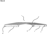
- a seventh step ( Figure 19 ) the lying top plate 4 is mounted on a left side wall section 2 and a right side wall section 3.
- both side wall sections consist of a folded hollow section 12.
- the top plate 4 is fastened to the side wall sections via welds along the entire longitudinal direction of the top plate 4 and over the entire surface of the support surface 5. In this way, a complete sliding hatch device 1 is manufactured.
- a sliding hatch device 1 is often part of a sliding hatch roof 28.
- Figure 12 illustrates such a sliding hatch roof 28, which consists of a set of successive bearing-mounted sliding hatch devices 1 which are horizontally slidable relative to each other. In this way, a sliding hatch roof 28 can completely span the cargo hold of a ship.
Landscapes
- Chemical & Material Sciences (AREA)
- Engineering & Computer Science (AREA)
- Combustion & Propulsion (AREA)
- Mechanical Engineering (AREA)
- Ocean & Marine Engineering (AREA)
- Specific Sealing Or Ventilating Devices For Doors And Windows (AREA)
- Operating, Guiding And Securing Of Roll- Type Closing Members (AREA)
Description
- The invention relates in a first aspect to a sliding hatch device for closing off a cargo hold of a ship or more generally for closing off a space, mainly made of aluminum and constructed from a lying top plate fastened to two upright side wall sections.
- In a second aspect, the invention relates to a sliding hatch roof for closing off a cargo hold of a ship or more generally for closing off a space, composed of a set of at least 2 sliding hatch devices.
- In a third aspect, the invention relates to a method for manufacturing a sliding hatch device for closing off a cargo hold of a ship or more generally for closing off a space.
- It is known to cover the cargo hold of ships with hatches which extend from one side coaming to the opposite side coaming of the cargo hold, several of which are required side by side to cover the entire hold.
- For some time now, such cargo hatch devices have been realized mainly in aluminum in order to keep the weight as low as possible. These cargo hatch devices are essentially constructed from two upright side wall sections which are connected via a lying top plate. It is known that various welding operations and metal cutting operations are carried out for the manufacture of such cargo hatches.
-
BE 899 006 -
BE 1 013 343 -
EP 1 155 955 B1claim 1 and a method for producing a sliding hatch device. - A problem with the known sliding hatch devices as described above is that the side wall sections of such sliding hatch devices are made up of a range of different aluminum sections. In the manufacture of such side wall sections, several welding operations and metal cutting operations must be carried out before a complete sliding hatch device can be manufactured. Welding operations and metal cutting operations are labor intensive and consequently cost intensive.
- Moreover, each welding operation provides an extra place where the material has a certain form of freedom. This is detrimental to the wear of components and to the functional life of a sliding hatch device.
- The present invention aims to find a solution to at least one of the aforementioned problems.
- For this purpose, in a first aspect, the invention provides a sliding hatch device suitable for closing off a cargo hold of a ship or more generally for closing off a space, substantially made of aluminum and constructed of a lying top plate fixed on two upright side wall sections, the side wall section comprising a closed longitudinally extended hollow section, which hollow section is folded according to at least one fold line, which fold line is provided with a material reduction.
- In a second aspect, the invention relates to a sliding hatch roof suitable for closing off a cargo hold of a ship or more generally for closing off a space, composed of a set of at least two sliding hatch devices, the sliding hatch devices being horizontally bearing-mounted with respect to each other.
- In a third aspect, the invention relates to a method for manufacturing a sliding hatch device according to the first aspect, the sliding hatch device being suitable for closing off a cargo hold of a ship or more generally for closing off a space, the method comprising the steps of:
- a. gathering a rectangular, flat aluminum plate;
- b. applying material reductions to a flat aluminum plate;
- c. folding a flat aluminum plate into a partially folded plate;
- d. assembling additional components to the partially folded plate;
- e. folding the partially folded plate into a closed longitudinally extended hollow section
- f. applying spot welds to the closed longitudinally extended hollow section;
- g. mounting a lying aluminum top plate on top of two upright hollow sections.
- The present invention has the advantage, among other things, that the use of welding operations and metal cutting operations can be limited. This by using folded side wall sections in the sliding hatch devices. Welding operations and metal cutting operations are a labor-intensive and time-consuming process. Therefore, by limiting welding operations, a considerable economic advantage can be gained in the manufacture of such sliding hatch devices.
- An additional advantage of limiting welding operations is that freedoms of the material are limited. In this way, the wear of components is limited, and this benefits the service life of the sliding hatch device.
- Another additional advantage is that a closed folded side wall section provides a more defined finish to the sliding hatch device. On the one hand, this is an aesthetic advantage, but as a result, no cargo from the cargo hold of a ship can be left behind on the inside of the side wall section of a sliding hatch device. In addition, a closed folded side wall section is more uniform than a side wall section that is composed of several sections.
- A surprising advantage of the present invention is that, through the use of a folded side wall section, substantially less customization and calculation work is required during the assembly of the components to the folded side wall section. This ensures an improved uniformity of the side wall sections since each component has a predetermined assembly location on the side wall section. In this case, no other interpretation is possible where the components have to be assembled and consequently the risk of incorrect assembly is considerably smaller. In addition, this also ensures an increased quality of the entire sliding hatch device.
- A particular advantage is that, through the use of a folded side wall section, there is a considerably better distribution of forces over the side wall section. As a result, the forces exerted by the top plate are better distributed over the entire side wall section. In addition, the support surface of the folded side wall section provides better support for the top plate. Overall, a sturdier side wall section is thus obtained according to the present invention.
- An advantage of the current method for manufacturing a sliding hatch device includes an advantage regarding the specific sequence of method steps c, d and e. Steps comprising, respectively, folding a flat aluminum plate into a partially folded plate, assembling additional components to the partially folded plate, and folding the partially folded plate into a closed, longitudinally extended hollow section. Because the folding of the hollow section comprises two steps, it is possible to mount the additional components via tongue and groove connections. This would be impossible if the hollow section were folded in one step. The tongue and groove connections have a considerable mechanical advantage over other mounting techniques such as welding.
- The invention relates to a sliding hatch device suitable for closing off a cargo hold of a ship or more generally for closing off a space, a sliding hatch roof composed of a set of at least two sliding hatch devices and a method for manufacturing such sliding hatch devices.
- Unless otherwise defined, all terms used in the description of the invention, including technical and scientific terms, have the meaning as commonly understood by a person skilled in the art to which the invention pertains. For a better understanding of the description of the invention, the following terms are explained explicitly.
- In this document, "a" and "the" refer to both the singular and the plural, unless the context presupposes otherwise. For example, "a segment" means one or more segments.
- The terms 'comprise', 'comprising', 'consist of', 'consisting of', 'provided with', 'have', 'having', 'include', 'including', 'contain', 'containing' are synonyms and are inclusive or open terms that indicate the presence of what follows, and which do not exclude or prevent the presence of other components, characteristics, elements, members, steps, as known from or disclosed in the prior art.
- When the term "around" or "about" is used in this document with a measurable quantity, a parameter, a duration or moment, and the like, then variations are meant of approx. 20% or less, preferably approx. 10% or less, more preferably approx. 5% or less, even more preferably approx. 1% or less, and even more preferably approx. 0.1% or less than and of the quoted value, insofar as such variations are applicable in the described invention. However, it must be understood that the value of a quantity used where the term "about" or "around" is used, is itself specifically disclosed.
- In a first aspect, the invention relates to a sliding hatch device suitable for closing off a cargo hold of a ship or more generally for closing off a space, substantially made of aluminum and constructed of a lying top plate fixed on two upright side wall sections, characterized in that the side wall section comprises a closed longitudinally extended hollow section, which hollow section is folded according to at least one fold line, which fold line is provided with a material reduction. In this context, a fold line is understood to mean a line along which one can or must easily fold; it can also be the line that has already been folded.
- Furthermore, material reduction is understood to mean that a material, in the case of the present invention being aluminum, is weakened by means of material removal, by any technique, at a certain area of the material.
- In an embodiment of the present invention, material reduction of a fold line will be arranged according to a line pattern. In a further embodiment, the percentage of material reduction at the level of the line pattern of a fold line will preferably be more than 50%, more preferably more than 75% and even more preferably more than 90%. A preferred embodiment of this line pattern comprises a repetition of longitudinally extended and cut-out U-shapes arranged one after the other along a line. This line pattern in combination with a material reduction percentage of more than 90% has the advantage that an optimal relationship between the retention of material strength and the foldability of the aluminum along the fold line is achieved.
- The configuration of a fold line by means of material reduction according to a line pattern has the advantage, among other things, that aluminum plates can be folded in a simple manner into a folded or more closed structure, without the aluminum plates breaking or considerable pressure having to be exerted on the aluminum plate.
- In an embodiment of the present invention, a sliding hatch device comprises a hollow section folded into a closed longitudinally extended polygon, preferably an irregular pentagon. In this case, the folded hollow section serves as a side wall section of a sliding hatch device.
- A closed side wall section has the advantage, inter alia, that no cargo from the cargo hold can be left behind on the inside of a side wall section. In addition, a closed hollow section comprises a defined finish to the side wall section where a minimum of welds are visible, which can be seen as an aesthetic advantage.
- A folded side wall section has the advantage, inter alia, that there is a considerably better distribution of forces over the side wall section. As a result, the forces exerted by the top plate are better distributed over the entire side wall section. In addition, the support surface of the folded side wall section provides better support for the top plate.
- In an embodiment of the present invention, a sliding hatch device comprises the lying top plate having a height that, from the center thereof, progressively decreases toward both ends thereof.
- In an embodiment of the present invention, a sliding hatch device comprises supporting aluminum reinforcing ribs attached to the inside of the cavity of the hollow section in the hollow section. Such reinforcing ribs provide the side wall section with additional load-bearing capacity. The attached reinforcing ribs have the advantage, among other things, that reinforcement of the side wall section can be realized as well as limiting the number of welding operations. An additional advantage of limiting welding operations is that freedoms of the material are limited. In this way, the wear of components is limited and this benefits the service life of the sliding hatch device.
- In an embodiment of the present invention, a sliding hatch device will span the opening of the cargo hold in the transverse direction of the ship, characterized in that a sliding hatch device rests with both outer edges on the side coamings of the ship. In this case, a side coaming comprises the upright side of the ship's hold, from the deck of an inland vessel. In a further embodiment of the present invention, at least one side coaming of a ship will be provided with rails according to the longitudinal position of the ship.
- In an embodiment of the present invention, additional material reductions will be provided in the hollow section for assembling additional components, which additional components include wheel housings, handle housings, latch housings and hatch hook housings. These additional components provide the side wall section and, by extension, a sliding hatch device with an optimal embodiment. In a further embodiment of the present invention, wheel housings will be provided with bearing-mounted or double-bearing wheels, which are slidable over a rail on the side coamings according to the longitudinal position of the ship.
- In a second aspect, the invention relates to a sliding hatch roof suitable for closing off a cargo hold of a ship or more generally for closing off a space, composed of a set of at least two sliding hatch devices, characterized in that the sliding hatch devices are horizontally bearing-mounted with respect to each other.
- The horizontally bearing-mounted positioning of a set of sliding hatch devices means that the vertical height of each successive sliding hatch increases progressively. This has the advantage, among other things, that they fit on top of each other when retracted and they do not take up more space than a single sliding hatch device.
- In an embodiment of the present invention, all sliding hatch devices of the sliding hatch roof will be slidable over a rail on the side coamings of a ship according to the longitudinal direction of the ship.
- In an embodiment of the present invention, seals in Ethylene Propylene Diene Monomer rubber (EPDM) will be fitted between the different sliding hatch devices of a sliding hatch roof. Such seals in EPDM have the advantage, among other things, that a sliding hatch roof is made watertight. In this way, the cargo in the cargo hold of a ship is protected against moisture.
- In a third aspect, the invention relates to a method for manufacturing a sliding hatch device according to the first aspect, the sliding hatch device being suitable for closing off a cargo hold of a ship or more generally for closing off a space, the method comprising the steps of:
- a. gathering a rectangular, flat aluminum plate;
- b. applying material reductions to a flat aluminum plate;
- c. folding a flat aluminum plate into a partially folded plate;
- d. assembling additional components to the partially folded plate;
- e. folding the partially folded plate into a closed longitudinally extended hollow section;
- f. applying spot welds to the closed longitudinally extended hollow section;
- g. mounting a lying aluminum top plate on top of two upright hollow sections.
- In an embodiment of the present invention, the method comprises material reductions being made by one of the following techniques: punching, cutting or laser cutting, which material reductions comprise fold lines according to a line pattern and cut-outs for additional components.
- In this context, punching comprises a processing technique in which shapes are cut from (sheet) material or parts of a structure are removed in some other way by means of compressive force, while the structure itself is supported at the rear. The openings made in the (sheet) material are the product and not the cut-out shapes.
- In an embodiment of the present invention, the method comprises additional components comprising wheel housings, handle housings, latch housings and hatch hook housings, which are attached to at least one side wall section of the sliding hatch device.
- In a preferred embodiment of the present invention, the method comprises manufacturing a hollow section from a flat aluminum plate, characterized in that the flat plate has a thickness of 1-100 mm, preferably 2-20 mm and even more preferably 3-10 mm; characterized in that the flat plate has a length of 1-25 m, preferably 3-12 m and even more preferably 6-8 m and characterized in that the flat plate has a width of 1-15 m, preferably 2-8 m and even more preferably 3-5 m.
- A preferred embodiment with a thickness between 3-10 mm has the advantage, among other things, that an optimum ratio is obtained between the retention of material strength, which is required for a side wall of a sliding hatch device, and the foldability of the aluminum along the fold line.
- An example suitable for understanding the current invention relates to a pleated side wall section suitable for the construction of a sliding hatch device.
- The present invention as described above has the advantage, among other things, that the use of welding operations can be limited to a minimum. Welding operations are a labor intensive and time consuming process. Therefore, by limiting welding operations, a considerable economic advantage can be gained in the manufacture of such sliding hatch devices.
- An additional advantage of the present invention is that a folded side wall section is more resistant to corrosion. On the one hand because welding is limited and on the other hand because the folded hollow section provides better drainage of condensation.
- A surprising advantage of the present invention is that, through the use of a folded side wall section, substantially less customization and calculation work is required during the assembly of the components to the folded side wall section. This ensures an improved uniformity of the side wall sections since each component has a predetermined assembly location on the side wall section. In this case, no other interpretation is possible where the components have to be assembled and consequently the risk of incorrect assembly is considerably smaller. In addition, this also ensures an increased quality of the entire sliding hatch device.
- An advantage of the current method for manufacturing a sliding hatch device includes an advantage regarding the specific sequence of method steps c, d and e. Steps comprising, respectively, folding a flat aluminum plate into a partially folded plate, assembling additional components to the partially folded plate, and folding the partially folded plate into a closed, longitudinally extended hollow section. Because the folding of the hollow section comprises two steps, it is possible to mount the additional components via tongue and groove connections. This would be impossible if the hollow section were folded in one step. The tongue and groove connections have a considerable mechanical advantage over other mounting techniques such as welding.
- Furthermore, the present invention involves significantly fewer metal cutting operations since no use is made of beam-shaped and prism-shaped hollow sections for supporting the side wall. The reduction of cutting operations also results in a time saving and therefore an economic advantage in manufacturing the present invention.
- The present invention not only offers a lower manufacturing cost for a sliding hatch device, but also a more defined finish of the side wall section so that no cargo from a ship's cargo hold can be left behind on the inside of the side wall section of a sliding hatch device.
- The detailed description describes the preferred embodiments of the present invention wherein a sliding hatch device is adapted for closing off the cargo hold of a ship. It goes without saying that, more generally, the described sliding hatch device can also be adapted for closing off other spaces, such as, for example, storage areas of buildings.
- In what follows, the invention is described by way of non-limiting examples and figures illustrating preferred embodiments of the invention, and which are not intended to and should not be interpreted as limiting the scope of the invention.
-
-
Figure 1 illustrates a perspective schematic representation of a prior art sliding hatch device. -
Figure 2 illustrates a schematic representation of a front view of a portion of a sliding hatch device fitted with a prior art side wall section. -
Figure 3 illustrates a perspective schematic representation of a sliding hatch device with a folded side wall section according to the invention. -
Figure 4 illustrates a schematic representation of a front view of a portion of a sliding hatch device fitted with a folded side wall section according to the invention. -
Figure 5 illustrates a schematic representation of a top view of a sliding hatch device. -
Figure 6 illustrates a perspective schematic representation of a pentagonal folded hollow section. -
Figure 7 illustrates a schematic representation of a front view of a pentagonal folded hollow section belonging to a low type sliding hatch device. -
Figure 8 illustrates a schematic representation of a front view of a pentagonal folded hollow section belonging to a middle type sliding hatch device. -
Figure 9 illustrates a schematic representation of a front view of a pentagonal folded hollow section belonging to a high type sliding hatch device. -
Figure 10 illustrates a schematic representation of a flat aluminum plate with several line patterns with material reductions. -
Figure 11 illustrates a schematic detail representation of a line pattern with material reduction. -
Figure 12 illustrates a perspective schematic representation of a sliding hatch roof made up of several sliding hatch devices. -
Figure 13 illustrates a perspective schematic representation of a flat aluminum plate. -
Figure 14 illustrates a perspective schematic representation of a flat aluminum plate on which material reductions are made by laser cutting. -
Figure 15 illustrates a perspective schematic representation of a partially folded plate. -
Figure 16 illustrates a perspective schematic representation of a partially folded plate with assembled additional components. -
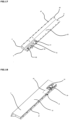
Figure 17 illustrates a perspective schematic representation of the inside of a closed folded hollow section. -
Figure 18 illustrates a perspective schematic representation of the inside of a closed folded hollow section. -
Figure 19 illustrates a perspective schematic representation of a sliding hatch device with a folded side wall section according to the invention. - In the different figures, the same reference numerals refer to the same elements.
- A sliding
hatch device 1 from the prior art is composed of a lying, sheet pile-shapedtop plate 4 which is fixed via apleated support surface 5 of, on the one hand, a left uprightside wall section 2 and, on the other hand, a right uprightside wall section 3. A leftside wall section 2 is constructed of aluminum beam-shapedhollow sections 6 which are fixed via welding to the inside of the outerupright side 7 of the leftside wall section 2. The beam-shapedhollow sections 6 are arranged at regular intervals along the entire longitudinal direction of the leftside wall section 2 and form a reinforcement that provides support between the outerupright side 7 and thesupport surface 5 of the leftside wall section 2. Furthermore, aluminum prism-shapedhollow sections 8 are arranged that connect thesupport surface 5 and the beam-shapedhollow sections 6. These prism-shapedhollow sections 8 are fixed via welds and attached to all beam-shapedhollow sections 6 arranged along the entire longitudinal direction of the leftside wall section 2. Thesupport surface 5 is provided with apleated drip lip 33. Thedrip lip 33 provides the side wall section with a drainage when condensation accumulates on the underside of the lyingtop plate 4. This drainage is designed to avoid corrosion to the welds of the prism-shapedhollow sections 8 and beam-shapedhollow sections 6. A steel beam-shapedwheel housing 9 is attached to the underside of the outerupright side 7 of the leftside wall section 2. Thiswheel housing 9 is fixed on the one hand via welds and on the other hand vianuts 10 on the inside of the leftside wall section 2. Thewheel housing 9 forms a housing for awheel 11. A slidinghatch device 1 from the prior art is mirror symmetrical with respect to the center axis of the longitudinal direction of the slidinghatch device 1, therefore a rightside wall section 3 can be seen as the mirror image of a leftside wall section 2. - Schematic representations of a sliding
hatch device 1 according to the present invention are shown inFigures 3 to 12 . Such a slidinghatch device 1 is composed of a lyingtop plate 4 which is fixed via apleated support surface 5 of, on the one hand, a left uprightside wall section 2 and, on the other hand, a right uprightside wall section 3. Both the leftside wall section 2 and the rightside wall section 3 are constructed from a pentagonal aluminum closed and longitudinally extended foldedhollow section 12. This foldedhollow section 12 is fastened via thesupport surface 5 to the underside of the ends of the longitudinal direction of the lyingtop plate 4 and this for the entire length of the foldedhollow section 12 and for the entire surface of thesupport surface 5. Such a slidinghatch device 1 is mirror symmetrical with respect to the center axis of the longitudinal direction of the slidinghatch device 1, therefore a leftside wall section 2 can be seen as the mirror image of a rightside wall section 3. - The folded
hollow section 12 is pentagonal and therefore comprises five sides. The outerupright side 7 is located along the outside of the foldedhollow section 12 and therefore along the outside of the slidinghatch device 1. The inner upright side 7' is arranged parallel to the outerupright side 7 and always has a shorter length than the outerupright side 7. Thesupport surface 5 is located on the top side of the foldedhollow section 12 and forms the mounting surface on which the lyingtop plate 4 is mounted. Thelower side 15 runs horizontally and connects the outerupright side 7 with the inner upright side 7'. The slopingside 16 connects thesupport surface 5 with the inner upright side 7'. This slopingside 16 always has a slope beta which depends on the type of slidinghatch device 1. The angle alpha forms the angle between the outerupright side 7 and thesupport surface 5 and also depends on the type of slidinghatch device 1. The angle gamma is the angle along the inside of the foldedhollow section 12 formed by the slopingside 16 and the inner upright side 7'. - The folded
hollow section 12 encloses a pentagonal hollow space in which various additional components are mounted. In the hollow space enclosed by the foldedhollow section 12, steel beam-shapedwheel housings 9, among other things, are mounted between the outerupright side 7 and the inner upright side 7' of the foldedhollow section 12. Thewheel housings 9 are closed along each side with the exception of the bottom which is open. Thesewheel housings 9 are attached at the level of arectangular opening 17 in the foldedhollow section 12, more specifically anopening 17 in the inner upright side 7'. Thewheel housing 9 is fixed in theopening 17 via aU-shaped aluminum section 18 on the one hand and nuts 10 on the other. A foldedhollow section 12 is provided with two wheel housings per side wall section, therefore a slidinghatch device 1 comprises four wheel housings in total. Eachwheel housing 9 is on one end of a foldedhollow section 12. Thewheel housing 9 forms a housing for awheel 11. Thiswheel 11 can be both a grooved wheel and a convex flat wheel. About half of thewheel 11 projects along the underside of thewheel housing 9. - In the hollow space enclosed by the folded
hollow section 12, aluminumhatch hook housings 19 are fastened in a rectangular opening 17' at the level of the inner upright side 7' of the foldedhollow section 12. Thehatch hook housing 19 is fastened in the rectangular opening 17' by means of nuts 10. The hatch hook housing forms a housing for ahatch hook 20. Thishatch hook 20 is U-shaped and protrudes along the underside of the foldedhollow section 12. In this case, the lower leg of theU-shaped hatch hook 20 is directed toward the inside of the slidinghatch device 1. A slidinghatch device 1 is provided with two hatch hooks 20 per slidinghatch device 1 wherein onehatch hook 20 is fastened per foldedhollow section 12. Thehatch hook 20 is located in each case at the end of the front side of the foldedhollow section 12 in the provided rectangular opening 17'. - In the hollow space enclosed by the folded
hollow section 12, flataluminum reinforcing ribs 21 are arranged. These reinforcingribs 21 have the same pentagonal shape as a cross-section of the foldedhollow section 12 and are attached via welds transverse to the outerupright side 7 of the foldedhollow section 12. In this way, a few reinforcingribs 21 are placed per foldedhollow section 12 distributed along the entire length direction of the foldedhollow section 12. When the foldedhollow section 12 is fully folded into a closed section, the reinforcingrib 21 is attached to each inner side of the foldedhollow section 12. - In the hollow space enclosed by the folded
hollow section 12, a rust-proof handle housing 22 and a rust-proof latch housing 23 are fastened. Thehandle housing 22 or latchhousing 23 are fastened in the same rectangular opening 17' in which thehatch hook housing 19 is fastened. Thehatch hook housing 19 is always more towards the end of the foldedhollow section 12 than thehandle housing 22 or latchhousing 23. For each foldedhollow section 12, either ahandle housing 22 or alatch housing 23 is fastened in each case. Consequently, a slidinghatch device 1 comprises onehandle housing 22 and onelatch housing 23 in total. - The
handle housing 22 is always located in the rightside wall section 3, along the port side. Thehandle housing 22 is fastened vianuts 10 in the opening 17' of the rightside wall section 3 along the rear end of the foldedhollow section 12. Thelatch housing 23 is always located in the leftside wall section 2, along the starboard side. Thelatch housing 23 is fastened vianuts 10 in the opening 17' of the leftside wall section 3 along the rear end of the foldedhollow section 12. - A sliding
hatch device 1 can be positioned in a bearing-mounted manner relative to the next slidinghatch device 1. Therefore, an adapted height is provided in both the leftside wall section 2 and the rightside wall section 3, depending on whether the slidinghatch device 1 belongs to a sliding hatch device of the low, middle or high type. A foldedhollow section 12 comprises five sides which comprise different dimensions depending on the type of slidinghatch device 1. Furthermore, a foldedhollow section 12 is also characterized by three angles alpha, beta and gamma, which may differ depending on the type of slidinghatch device 1.Figures 7 to 9 illustrate these dimensions of a low, medium and high type slidingshutter device 1 respectively. - The low type sliding
hatch device 1 comprises an angle alpha of preferably between 90°-110°, more preferably between 92°-100° and even more preferably between 95°-99°. The angle beta preferably comprises 30°-50°, more preferably between 35°-45° and even more preferably between 38°-42°. The angle gamma preferably comprises 210°-230°, more preferably between 215°-225° and even more preferably between 218°-222°. The outerupright side 7 has a length of preferably 180-250 mm, more preferably 200-220 mm and even more preferably 205-215 mm. The inner upright side 7' has a length of preferably 170-240 mm, more preferably 180-200 mm and even more preferably 185-195 mm. Thesupport surface 5 has a length of preferably 100-170 mm, more preferably 120-140 mm and even more preferably 125-135 mm. The slopingside 16 has a length of preferably 60-130 mm, more preferably 80-100 mm and even more preferably 85-95 mm. Thelower side 15 preferably has a length of about 1/3 of the length of thesupport surface 5. - The middle type sliding
hatch device 1 comprises an angle alpha of preferably between 90°-110°, more preferably between 92°-100° and even more preferably between 95°-99°. The angle beta preferably comprises 40°-60°, more preferably between 45°-55° and even more preferably between 48°-52°. The angle gamma preferably comprises 210°-230°, more preferably between 215°-225° and even more preferably between 218°-222°. The outerupright side 7 has a length of preferably 330-400 mm, more preferably 360-380 mm and even more preferably 365-375 mm. The inner upright side 7' has a length of preferably 330-400 mm, more preferably 355-375 mm and even more preferably 260-270 mm. Thesupport surface 5 has a length of preferably 130-200 mm, more preferably 160-180 mm and even more preferably 165-175 mm. The slopingside 16 has a length of preferably 150-220 mm, more preferably 180-200 mm and even more preferably 185-195 mm. Thelower side 15 preferably has a length of about 1/3 of the length of thesupport surface 5. - The high type sliding
hatch device 1 comprises an angle alpha of preferably between 90°-110°, more preferably between 92°-100° and even more preferably between 95°-99°. The angle beta preferably comprises 40°-60°, more preferably between 45°-55° and even more preferably between 48°-52°. The angle gamma preferably comprises 210°-230°, more preferably between 215°-225° and even more preferably between 218°-222°. The outerupright side 7 has a length of preferably 500-570 mm, more preferably 520-540 mm and even more preferably 525-535 mm. The inner upright side 7' has a length of preferably 390-460 mm, more preferably 415-435 mm and even more preferably 420-430 mm. Thesupport surface 5 has a length of preferably 130-200 mm, more preferably 160-180 mm and even more preferably 165-175 mm. The slopingside 16 has a length of preferably 150-220 mm, more preferably 180-200 mm and even more preferably 185-195 mm. Thelower side 15 preferably has a length of about 1/3 of the length of thesupport surface 5. - A pentagonal folded
hollow section 12 comprises fourfold lines 13, which are arranged in the longitudinal direction of an elongatedrectangular aluminum plate 14 from which the foldedhollow section 12 is produced. Folding theplate 14 according to these fourfold lines 13 results in a pentagonal and longitudinally extended foldedhollow section 12. - Each
fold line 13 is made up of aline pattern 24 of successively extendedU-shaped material reductions 25.Figure 10 illustrates analuminum plate 14 with severaldifferent line patterns 24 wherein different sizes ofmaterial reductions 25 are used. The legs of theU-shaped material reductions 25 are directed alternately upwards or downwards. A detail of this can be seen inFigure 11 . - The manufacture of a sliding
hatch device 1 comprises various steps:
In a first step (Figure 13 ), a blankrectangular aluminum plate 14 with a thickness of 4 mm is collected. - In a second step (
Figure 14 ), material reductions are applied to theplate 14 by means of a machine suitable for applying these material reductions. An example of such a machine is a laser cutting machine. The first material reductions applied are theU-shaped material reductions 25. These are arranged according to aline pattern 24 which runs along the longitudinal direction of theplate 14. For example, a total of fourline patterns 24 are applied to theplate 14, all of which form afold line 13', 13", 13"' and 13"". Furthermore, four rectangular openings are also made in theplate 14, in fact these openings can also be seen as material reductions. These openings comprise the opening for thewheel housing 17, the two openings for thehatch hook housing 17' and 17" and the opening for thewheel 26. - In a third step (
Figure 15 ), theplate 14 is folded according to the appliedfold lines 13 by means of a press brake. It is folded according to all foldlines 13 with the exception offold line 13". Foldline 13‴ and foldline 13"" are folded in such a way that the folded parts form an angle of 90° with the side which will later become the outerupright side 7 of the foldedhollow section 12. In this case, both folded parts are parallel to each other. Fold line 13' is folded in the opposite direction thanfold line 13‴ and 13"" are folded. In this way, a partially folded plate 14' is obtained. - In a fourth step (
Figure 16 ), additional components are assembled to the partially folded plate 14'. The reinforcingribs 21 are mounted transversely on the outerupright side 7 via welds. Thewheel housing 9 is also mounted on the outerupright side 7 at the level of thewheel housing opening 17 vianuts 10 and a U-section 18. Furthermore, a hatch hook housing with either a handle housing or a latch housing is attached and this at the height of theopening 17". - In a fifth step (
Figure 17 ), the partially folded plate 14' is further folded according to foldline 13" into the folded pentagonalhollow section 12. In this case, after the folding, afew spot welds 27 are applied to thefold line 13", this at a regular distance and along the entire length of thefold line 13". - In a sixth step (
Figure 18 ), a few spot welds are attached to the underside of the foldedhollow section 12 at the level of the overhanging part of the inner upright side 7' of the foldedhollow section 12. The spot welds 27 are also arranged at a regular distance and over the entire length of the foldedhollow section 12. - In a seventh step (
Figure 19 ), the lyingtop plate 4 is mounted on a leftside wall section 2 and a rightside wall section 3. In this case, both side wall sections consist of a foldedhollow section 12. Thetop plate 4 is fastened to the side wall sections via welds along the entire longitudinal direction of thetop plate 4 and over the entire surface of thesupport surface 5. In this way, a complete slidinghatch device 1 is manufactured. - A sliding
hatch device 1 is often part of a slidinghatch roof 28.Figure 12 illustrates such a slidinghatch roof 28, which consists of a set of successive bearing-mounted slidinghatch devices 1 which are horizontally slidable relative to each other. In this way, a slidinghatch roof 28 can completely span the cargo hold of a ship. - Below is an overview of the meaning of the numbers and letters used in the figures:
- 1
- sliding hatch device
- 2
- left side wall section
- 3
- right side wall section
- 4
- lying top plate
- 5
- support surface of side wall section
- 6
- beam-shaped hollow sections
- 7
- outer upright side of side wall section
- 7'
- inner upright side of side wall section
- 8
- prism-shaped hollow sections
- 9
- wheel housing
- 10
- nut
- 11
- wheel
- 12
- folded hollow section
- 13
- fold line
- 13'
- first fold line
- 13"
- second fold line
- 13‴
- third fold line
- 13""
- fourth fold line
- 14
- plate
- 14'
- partially folded plate
- 15
- lower side of side wall section
- 16
- sloping side of side wall section
- 17
- opening for wheel housing
- 17'
- opening for hatch hook housing (inside side wall section)
- 17"
- opening for hatch hook housing (outside side wall section)
- 18
- U-section
- 19
- hatch hook housing
- 20
- hatch hook
- 21
- reinforcement rib
- 22
- handle housing
- 23
- latch housing
- 24
- line pattern
- 25
- U-shaped material reductions
- 26
- wheel opening
- 27
- spot welds
- 28
- sliding hatch roof
- 29
- port side
- 30
- starboard side
- 31
- front sliding hatch device
- 32
- rear sliding hatch device
- 33
- drip lip
- α
- angle enclosed by outer upright side of side wall section and support surface of side wall section
- β
- angle enclosed by support surface of side wall section and sloping side of side wall section
- γ
- angle enclosed by sloping side of side wall section and inner upright side of side wall section
Claims (14)
- A sliding hatch device suitable for closing off a cargo hold of a ship or more generally for closing off a space, substantially made of aluminum and constructed of a lying top plate fixed on two upright side wall sections, wherein the side wall section comprises a closed longitudinally extended hollow section, which hollow section is folded according to at least one fold line,
characterised in that said fold line is provided with a material reduction. - The sliding hatch device according to the preceding claim, wherein material reduction of a fold line is arranged according to a line pattern.
- The sliding hatch device according to any of the preceding claims, wherein
a hollow section is folded into a closed longitudinally extended polygon, preferably an irregular pentagon. - The sliding hatch device according to any of the preceding wherein
the lying top plate has a height which, from its center, decreases progressively towards both ends thereof. - The sliding hatch device according to any of the preceding claims, wherein
supporting aluminum reinforcing ribs are attached to the inside of the cavity of the hollow section. - The sliding hatch device according to any of the preceding claims, which in use spans the opening of the cargo hold in the transverse direction of the ship, and rests with both outer edges on the ship's side coamings.
- The sliding hatch device according to the preceding claim, wherein in use the at least one side coaming of a ship is provided with rails according to the longitudinal position of the ship.
- The sliding hatch device according to any of the preceding claims, wherein additional material reductions are provided in the hollow section for assembling additional components, which additional components include wheel housings, handle housings, latch housings and hatch hook housings.
- The sliding hatch device according to the preceding claim, wherein wheel housings are provided with bearing-mounted or double-bearing wheels, which in use are slidable over a rail on the side coamings according to the longitudinal position of the ship.
- A sliding hatch roof suitable for closing off a cargo hold of a ship or more generally for closing off a space, composed of a set of at least 2 sliding hatch devices as described according to claims 1-9, wherein the sliding hatch devices are horizontally bearing-mounted with respect to each other.
- The sliding hatch roof according to the preceding claim, wherein all sliding hatch devices of the sliding hatch roof are slidable over a rail on the side coamings of a ship according to the longitudinal direction of the ship.
- Method for manufacturing a sliding hatch device according to any of claims 1-9, the sliding hatch device being suitable for closing off a cargo hold of a ship or more generally closing off a space, the method comprising the steps of:a. gathering a rectangular, flat aluminum plate;b. applying material reductions to a flat aluminum plate;c. folding a flat aluminum plate into a partially folded plate;d. assembling additional components to the partially folded plate;e. folding the partially folded plate into a closed longitudinally extended hollow sectionf. applying spot welds to the closed longitudinally extended hollow section;g. mounting a lying aluminum top plate on top of two upright hollow sections.
- Method according to the preceding claim, wherein material reductions are made by one of the following techniques: punching, cutting or laser cutting, which material reductions comprise fold lines according to a line pattern and cut-outs for additional components.
- Method according to any of the preceding claims, wherein additional components comprise wheel housings, handle housings, latch housings and hatch hook housings, which are attached to at least one side wall section of the sliding hatch device.
Applications Claiming Priority (1)
| Application Number | Priority Date | Filing Date | Title |
|---|---|---|---|
| BE20215883A BE1029925B1 (en) | 2021-11-16 | 2021-11-16 | Sliding shutter device and improved side wall for it as well as a method of manufacture |
Publications (3)
| Publication Number | Publication Date |
|---|---|
| EP4180312A1 EP4180312A1 (en) | 2023-05-17 |
| EP4180312C0 EP4180312C0 (en) | 2024-07-17 |
| EP4180312B1 true EP4180312B1 (en) | 2024-07-17 |
Family
ID=78695411
Family Applications (1)
| Application Number | Title | Priority Date | Filing Date |
|---|---|---|---|
| EP22207824.8A Active EP4180312B1 (en) | 2021-11-16 | 2022-11-16 | Sliding hatch device and improved sidewall therefore as well as a method of manufacture |
Country Status (2)
| Country | Link |
|---|---|
| EP (1) | EP4180312B1 (en) |
| BE (1) | BE1029925B1 (en) |
Family Cites Families (5)
| Publication number | Priority date | Publication date | Assignee | Title |
|---|---|---|---|---|
| BE899006A (en) | 1984-02-27 | 1984-06-18 | Blommaert Pv | IMPROVED HOOD FOR SHIPS |
| DD272272A1 (en) * | 1988-05-26 | 1989-10-04 | Elbewerften Boizenburg Rosslau | ROLLER ASSEMBLY IN LUKEN COVERS |
| BE1013343A3 (en) | 2000-03-08 | 2001-12-04 | Blommaert Bv Met Beperkte Aans | Improved hatch. |
| BE1013711A5 (en) * | 2000-05-18 | 2002-06-04 | G M Baeck Arthur | Ship liege for covering a wide open. |
| US6877349B2 (en) * | 2000-08-17 | 2005-04-12 | Industrial Origami, Llc | Method for precision bending of sheet of materials, slit sheets fabrication process |
-
2021
- 2021-11-16 BE BE20215883A patent/BE1029925B1/en active IP Right Grant
-
2022
- 2022-11-16 EP EP22207824.8A patent/EP4180312B1/en active Active
Also Published As
| Publication number | Publication date |
|---|---|
| BE1029925B1 (en) | 2023-06-19 |
| EP4180312C0 (en) | 2024-07-17 |
| BE1029925A1 (en) | 2023-06-12 |
| EP4180312A1 (en) | 2023-05-17 |
Similar Documents
| Publication | Publication Date | Title |
|---|---|---|
| CN102481954A (en) | Hybrid reinforcement structure | |
| EP4180312A1 (en) | Sliding hatch device and improved sidewall therefore as well as a method of manufacture | |
| US5996524A (en) | Boat anchor davit | |
| KR101258929B1 (en) | Vessel having welding corrugated plate type bulkhead | |
| US12409921B1 (en) | Pontoon kicker motor mount | |
| DE69419322T2 (en) | CASE DEVICE | |
| US6532889B1 (en) | Aluminum fishing boat | |
| FI124856B (en) | Shipping arrangements for shipping rolls | |
| KR20080012961A (en) | Lashing device for ship cargo and cargo deck provided with the lashing device | |
| JP7129435B2 (en) | Removable flap section for ship ramps | |
| US20070295264A1 (en) | Under-deck storage unit for pontoon boat | |
| US6250662B1 (en) | Boat trailer having aluminum adjustable bunks | |
| KR20130035028A (en) | Structure of floor plate of double bottom in large ore carrier | |
| KR20120012110A (en) | Aluminum vessel using aluminum extrusion | |
| KR200440766Y1 (en) | Lashing Road Rack with Handrail | |
| JP2502454B2 (en) | Disaster prevention equipment for container ships | |
| CN212828926U (en) | Ship deck oil blocking structure | |
| RU2286914C1 (en) | Hull of tanker for liquid cargoes in bulk | |
| WO2015140823A2 (en) | A modified deck cell-guide system for deck stowage of containers | |
| CA2830723A1 (en) | Boat cover assembly | |
| CN212099236U (en) | Marine stainless steel floor plate capable of improving bearing capacity | |
| US11745836B1 (en) | Inflatable kayaks with non-planar hulls | |
| KR100650607B1 (en) | Double hull ship with partially horizontal longitudinal and partially longitudinal profiles | |
| US20260042508A1 (en) | Anchor windlass system | |
| EP0267168A1 (en) | Decks for marine tankers |
Legal Events
| Date | Code | Title | Description |
|---|---|---|---|
| PUAI | Public reference made under article 153(3) epc to a published international application that has entered the european phase |
Free format text: ORIGINAL CODE: 0009012 |
|
| STAA | Information on the status of an ep patent application or granted ep patent |
Free format text: STATUS: THE APPLICATION HAS BEEN PUBLISHED |
|
| AK | Designated contracting states |
Kind code of ref document: A1 Designated state(s): AL AT BE BG CH CY CZ DE DK EE ES FI FR GB GR HR HU IE IS IT LI LT LU LV MC ME MK MT NL NO PL PT RO RS SE SI SK SM TR |
|
| STAA | Information on the status of an ep patent application or granted ep patent |
Free format text: STATUS: REQUEST FOR EXAMINATION WAS MADE |
|
| 17P | Request for examination filed |
Effective date: 20231106 |
|
| RBV | Designated contracting states (corrected) |
Designated state(s): AL AT BE BG CH CY CZ DE DK EE ES FI FR GB GR HR HU IE IS IT LI LT LU LV MC ME MK MT NL NO PL PT RO RS SE SI SK SM TR |
|
| GRAP | Despatch of communication of intention to grant a patent |
Free format text: ORIGINAL CODE: EPIDOSNIGR1 |
|
| STAA | Information on the status of an ep patent application or granted ep patent |
Free format text: STATUS: GRANT OF PATENT IS INTENDED |
|
| INTG | Intention to grant announced |
Effective date: 20240206 |
|
| GRAS | Grant fee paid |
Free format text: ORIGINAL CODE: EPIDOSNIGR3 |
|
| GRAA | (expected) grant |
Free format text: ORIGINAL CODE: 0009210 |
|
| STAA | Information on the status of an ep patent application or granted ep patent |
Free format text: STATUS: THE PATENT HAS BEEN GRANTED |
|
| AK | Designated contracting states |
Kind code of ref document: B1 Designated state(s): AL AT BE BG CH CY CZ DE DK EE ES FI FR GB GR HR HU IE IS IT LI LT LU LV MC ME MK MT NL NO PL PT RO RS SE SI SK SM TR |
|
| REG | Reference to a national code |
Ref country code: CH Ref legal event code: EP |
|
| REG | Reference to a national code |
Ref country code: DE Ref legal event code: R096 Ref document number: 602022004631 Country of ref document: DE |
|
| REG | Reference to a national code |
Ref country code: IE Ref legal event code: FG4D |
|
| U01 | Request for unitary effect filed |
Effective date: 20240816 |
|
| U07 | Unitary effect registered |
Designated state(s): AT BE BG DE DK EE FI FR IT LT LU LV MT NL PT SE SI Effective date: 20240827 |
|
| U20 | Renewal fee for the european patent with unitary effect paid |
Year of fee payment: 3 Effective date: 20241126 |
|
| PG25 | Lapsed in a contracting state [announced via postgrant information from national office to epo] |
Ref country code: NO Free format text: LAPSE BECAUSE OF FAILURE TO SUBMIT A TRANSLATION OF THE DESCRIPTION OR TO PAY THE FEE WITHIN THE PRESCRIBED TIME-LIMIT Effective date: 20241017 |
|
| PG25 | Lapsed in a contracting state [announced via postgrant information from national office to epo] |
Ref country code: PL Free format text: LAPSE BECAUSE OF FAILURE TO SUBMIT A TRANSLATION OF THE DESCRIPTION OR TO PAY THE FEE WITHIN THE PRESCRIBED TIME-LIMIT Effective date: 20240717 Ref country code: GR Free format text: LAPSE BECAUSE OF FAILURE TO SUBMIT A TRANSLATION OF THE DESCRIPTION OR TO PAY THE FEE WITHIN THE PRESCRIBED TIME-LIMIT Effective date: 20241018 |
|
| PG25 | Lapsed in a contracting state [announced via postgrant information from national office to epo] |
Ref country code: IS Free format text: LAPSE BECAUSE OF FAILURE TO SUBMIT A TRANSLATION OF THE DESCRIPTION OR TO PAY THE FEE WITHIN THE PRESCRIBED TIME-LIMIT Effective date: 20241117 |
|
| PG25 | Lapsed in a contracting state [announced via postgrant information from national office to epo] |
Ref country code: HR Free format text: LAPSE BECAUSE OF FAILURE TO SUBMIT A TRANSLATION OF THE DESCRIPTION OR TO PAY THE FEE WITHIN THE PRESCRIBED TIME-LIMIT Effective date: 20240717 |
|
| PG25 | Lapsed in a contracting state [announced via postgrant information from national office to epo] |
Ref country code: RS Free format text: LAPSE BECAUSE OF FAILURE TO SUBMIT A TRANSLATION OF THE DESCRIPTION OR TO PAY THE FEE WITHIN THE PRESCRIBED TIME-LIMIT Effective date: 20241017 Ref country code: ES Free format text: LAPSE BECAUSE OF FAILURE TO SUBMIT A TRANSLATION OF THE DESCRIPTION OR TO PAY THE FEE WITHIN THE PRESCRIBED TIME-LIMIT Effective date: 20240717 |
|
| PG25 | Lapsed in a contracting state [announced via postgrant information from national office to epo] |
Ref country code: RS Free format text: LAPSE BECAUSE OF FAILURE TO SUBMIT A TRANSLATION OF THE DESCRIPTION OR TO PAY THE FEE WITHIN THE PRESCRIBED TIME-LIMIT Effective date: 20241017 Ref country code: PL Free format text: LAPSE BECAUSE OF FAILURE TO SUBMIT A TRANSLATION OF THE DESCRIPTION OR TO PAY THE FEE WITHIN THE PRESCRIBED TIME-LIMIT Effective date: 20240717 Ref country code: NO Free format text: LAPSE BECAUSE OF FAILURE TO SUBMIT A TRANSLATION OF THE DESCRIPTION OR TO PAY THE FEE WITHIN THE PRESCRIBED TIME-LIMIT Effective date: 20241017 Ref country code: IS Free format text: LAPSE BECAUSE OF FAILURE TO SUBMIT A TRANSLATION OF THE DESCRIPTION OR TO PAY THE FEE WITHIN THE PRESCRIBED TIME-LIMIT Effective date: 20241117 Ref country code: HR Free format text: LAPSE BECAUSE OF FAILURE TO SUBMIT A TRANSLATION OF THE DESCRIPTION OR TO PAY THE FEE WITHIN THE PRESCRIBED TIME-LIMIT Effective date: 20240717 Ref country code: GR Free format text: LAPSE BECAUSE OF FAILURE TO SUBMIT A TRANSLATION OF THE DESCRIPTION OR TO PAY THE FEE WITHIN THE PRESCRIBED TIME-LIMIT Effective date: 20241018 Ref country code: ES Free format text: LAPSE BECAUSE OF FAILURE TO SUBMIT A TRANSLATION OF THE DESCRIPTION OR TO PAY THE FEE WITHIN THE PRESCRIBED TIME-LIMIT Effective date: 20240717 |
|
| PG25 | Lapsed in a contracting state [announced via postgrant information from national office to epo] |
Ref country code: SM Free format text: LAPSE BECAUSE OF FAILURE TO SUBMIT A TRANSLATION OF THE DESCRIPTION OR TO PAY THE FEE WITHIN THE PRESCRIBED TIME-LIMIT Effective date: 20240717 |
|
| PG25 | Lapsed in a contracting state [announced via postgrant information from national office to epo] |
Ref country code: CZ Free format text: LAPSE BECAUSE OF FAILURE TO SUBMIT A TRANSLATION OF THE DESCRIPTION OR TO PAY THE FEE WITHIN THE PRESCRIBED TIME-LIMIT Effective date: 20240717 |
|
| PG25 | Lapsed in a contracting state [announced via postgrant information from national office to epo] |
Ref country code: SK Free format text: LAPSE BECAUSE OF FAILURE TO SUBMIT A TRANSLATION OF THE DESCRIPTION OR TO PAY THE FEE WITHIN THE PRESCRIBED TIME-LIMIT Effective date: 20240717 |
|
| PLBE | No opposition filed within time limit |
Free format text: ORIGINAL CODE: 0009261 |
|
| STAA | Information on the status of an ep patent application or granted ep patent |
Free format text: STATUS: NO OPPOSITION FILED WITHIN TIME LIMIT |
|
| 26N | No opposition filed |
Effective date: 20250422 |
|
| PG25 | Lapsed in a contracting state [announced via postgrant information from national office to epo] |
Ref country code: MC Free format text: LAPSE BECAUSE OF FAILURE TO SUBMIT A TRANSLATION OF THE DESCRIPTION OR TO PAY THE FEE WITHIN THE PRESCRIBED TIME-LIMIT Effective date: 20240717 |
|
| PG25 | Lapsed in a contracting state [announced via postgrant information from national office to epo] |
Ref country code: IE Free format text: LAPSE BECAUSE OF NON-PAYMENT OF DUE FEES Effective date: 20241116 |
|
| PG25 | Lapsed in a contracting state [announced via postgrant information from national office to epo] |
Ref country code: RO Free format text: LAPSE BECAUSE OF FAILURE TO SUBMIT A TRANSLATION OF THE DESCRIPTION OR TO PAY THE FEE WITHIN THE PRESCRIBED TIME-LIMIT Effective date: 20240717 |
|
| U20 | Renewal fee for the european patent with unitary effect paid |
Year of fee payment: 4 Effective date: 20251127 |
|
| PG25 | Lapsed in a contracting state [announced via postgrant information from national office to epo] |
Ref country code: HU Free format text: LAPSE BECAUSE OF FAILURE TO SUBMIT A TRANSLATION OF THE DESCRIPTION OR TO PAY THE FEE WITHIN THE PRESCRIBED TIME-LIMIT; INVALID AB INITIO Effective date: 20221116 |
|
| PG25 | Lapsed in a contracting state [announced via postgrant information from national office to epo] |
Ref country code: CY Free format text: LAPSE BECAUSE OF FAILURE TO SUBMIT A TRANSLATION OF THE DESCRIPTION OR TO PAY THE FEE WITHIN THE PRESCRIBED TIME-LIMIT; INVALID AB INITIO Effective date: 20221116 |