EP4180263A1 - System zur erweiterung der reichweite von elektrischen energiespeicher- und -versorgungsvorrichtungen für elektro- oder hybridfahrzeuge - Google Patents
System zur erweiterung der reichweite von elektrischen energiespeicher- und -versorgungsvorrichtungen für elektro- oder hybridfahrzeuge Download PDFInfo
- Publication number
- EP4180263A1 EP4180263A1 EP22166987.2A EP22166987A EP4180263A1 EP 4180263 A1 EP4180263 A1 EP 4180263A1 EP 22166987 A EP22166987 A EP 22166987A EP 4180263 A1 EP4180263 A1 EP 4180263A1
- Authority
- EP
- European Patent Office
- Prior art keywords
- high voltage
- range extension
- connection
- power contactor
- subsystem
- Prior art date
- Legal status (The legal status is an assumption and is not a legal conclusion. Google has not performed a legal analysis and makes no representation as to the accuracy of the status listed.)
- Pending
Links
Images


Classifications
-
- B—PERFORMING OPERATIONS; TRANSPORTING
- B60—VEHICLES IN GENERAL
- B60L—PROPULSION OF ELECTRICALLY-PROPELLED VEHICLES; SUPPLYING ELECTRIC POWER FOR AUXILIARY EQUIPMENT OF ELECTRICALLY-PROPELLED VEHICLES; ELECTRODYNAMIC BRAKE SYSTEMS FOR VEHICLES IN GENERAL; MAGNETIC SUSPENSION OR LEVITATION FOR VEHICLES; MONITORING OPERATING VARIABLES OF ELECTRICALLY-PROPELLED VEHICLES; ELECTRIC SAFETY DEVICES FOR ELECTRICALLY-PROPELLED VEHICLES
- B60L50/00—Electric propulsion with power supplied within the vehicle
- B60L50/50—Electric propulsion with power supplied within the vehicle using propulsion power supplied by batteries or fuel cells
- B60L50/60—Electric propulsion with power supplied within the vehicle using propulsion power supplied by batteries or fuel cells using power supplied by batteries
- B60L50/61—Electric propulsion with power supplied within the vehicle using propulsion power supplied by batteries or fuel cells using power supplied by batteries by batteries charged by engine-driven generators, e.g. series hybrid electric vehicles
- B60L50/62—Electric propulsion with power supplied within the vehicle using propulsion power supplied by batteries or fuel cells using power supplied by batteries by batteries charged by engine-driven generators, e.g. series hybrid electric vehicles charged by low-power generators primarily intended to support the batteries, e.g. range extenders
-
- B—PERFORMING OPERATIONS; TRANSPORTING
- B60—VEHICLES IN GENERAL
- B60L—PROPULSION OF ELECTRICALLY-PROPELLED VEHICLES; SUPPLYING ELECTRIC POWER FOR AUXILIARY EQUIPMENT OF ELECTRICALLY-PROPELLED VEHICLES; ELECTRODYNAMIC BRAKE SYSTEMS FOR VEHICLES IN GENERAL; MAGNETIC SUSPENSION OR LEVITATION FOR VEHICLES; MONITORING OPERATING VARIABLES OF ELECTRICALLY-PROPELLED VEHICLES; ELECTRIC SAFETY DEVICES FOR ELECTRICALLY-PROPELLED VEHICLES
- B60L53/00—Methods of charging batteries, specially adapted for electric vehicles; Charging stations or on-board charging equipment therefor; Exchange of energy storage elements in electric vehicles
- B60L53/20—Methods of charging batteries, specially adapted for electric vehicles; Charging stations or on-board charging equipment therefor; Exchange of energy storage elements in electric vehicles characterised by converters located in the vehicle
- B60L53/22—Constructional details or arrangements of charging converters specially adapted for charging electric vehicles
-
- B—PERFORMING OPERATIONS; TRANSPORTING
- B60—VEHICLES IN GENERAL
- B60L—PROPULSION OF ELECTRICALLY-PROPELLED VEHICLES; SUPPLYING ELECTRIC POWER FOR AUXILIARY EQUIPMENT OF ELECTRICALLY-PROPELLED VEHICLES; ELECTRODYNAMIC BRAKE SYSTEMS FOR VEHICLES IN GENERAL; MAGNETIC SUSPENSION OR LEVITATION FOR VEHICLES; MONITORING OPERATING VARIABLES OF ELECTRICALLY-PROPELLED VEHICLES; ELECTRIC SAFETY DEVICES FOR ELECTRICALLY-PROPELLED VEHICLES
- B60L53/00—Methods of charging batteries, specially adapted for electric vehicles; Charging stations or on-board charging equipment therefor; Exchange of energy storage elements in electric vehicles
- B60L53/10—Methods of charging batteries, specially adapted for electric vehicles; Charging stations or on-board charging equipment therefor; Exchange of energy storage elements in electric vehicles characterised by the energy transfer between the charging station and the vehicle
- B60L53/14—Conductive energy transfer
- B60L53/16—Connectors, e.g. plugs or sockets, specially adapted for charging electric vehicles
-
- B—PERFORMING OPERATIONS; TRANSPORTING
- B60—VEHICLES IN GENERAL
- B60L—PROPULSION OF ELECTRICALLY-PROPELLED VEHICLES; SUPPLYING ELECTRIC POWER FOR AUXILIARY EQUIPMENT OF ELECTRICALLY-PROPELLED VEHICLES; ELECTRODYNAMIC BRAKE SYSTEMS FOR VEHICLES IN GENERAL; MAGNETIC SUSPENSION OR LEVITATION FOR VEHICLES; MONITORING OPERATING VARIABLES OF ELECTRICALLY-PROPELLED VEHICLES; ELECTRIC SAFETY DEVICES FOR ELECTRICALLY-PROPELLED VEHICLES
- B60L53/00—Methods of charging batteries, specially adapted for electric vehicles; Charging stations or on-board charging equipment therefor; Exchange of energy storage elements in electric vehicles
- B60L53/30—Constructional details of charging stations
-
- B—PERFORMING OPERATIONS; TRANSPORTING
- B60—VEHICLES IN GENERAL
- B60L—PROPULSION OF ELECTRICALLY-PROPELLED VEHICLES; SUPPLYING ELECTRIC POWER FOR AUXILIARY EQUIPMENT OF ELECTRICALLY-PROPELLED VEHICLES; ELECTRODYNAMIC BRAKE SYSTEMS FOR VEHICLES IN GENERAL; MAGNETIC SUSPENSION OR LEVITATION FOR VEHICLES; MONITORING OPERATING VARIABLES OF ELECTRICALLY-PROPELLED VEHICLES; ELECTRIC SAFETY DEVICES FOR ELECTRICALLY-PROPELLED VEHICLES
- B60L53/00—Methods of charging batteries, specially adapted for electric vehicles; Charging stations or on-board charging equipment therefor; Exchange of energy storage elements in electric vehicles
- B60L53/30—Constructional details of charging stations
- B60L53/305—Communication interfaces
-
- B—PERFORMING OPERATIONS; TRANSPORTING
- B60—VEHICLES IN GENERAL
- B60L—PROPULSION OF ELECTRICALLY-PROPELLED VEHICLES; SUPPLYING ELECTRIC POWER FOR AUXILIARY EQUIPMENT OF ELECTRICALLY-PROPELLED VEHICLES; ELECTRODYNAMIC BRAKE SYSTEMS FOR VEHICLES IN GENERAL; MAGNETIC SUSPENSION OR LEVITATION FOR VEHICLES; MONITORING OPERATING VARIABLES OF ELECTRICALLY-PROPELLED VEHICLES; ELECTRIC SAFETY DEVICES FOR ELECTRICALLY-PROPELLED VEHICLES
- B60L53/00—Methods of charging batteries, specially adapted for electric vehicles; Charging stations or on-board charging equipment therefor; Exchange of energy storage elements in electric vehicles
- B60L53/80—Exchanging energy storage elements, e.g. removable batteries
-
- B—PERFORMING OPERATIONS; TRANSPORTING
- B60—VEHICLES IN GENERAL
- B60L—PROPULSION OF ELECTRICALLY-PROPELLED VEHICLES; SUPPLYING ELECTRIC POWER FOR AUXILIARY EQUIPMENT OF ELECTRICALLY-PROPELLED VEHICLES; ELECTRODYNAMIC BRAKE SYSTEMS FOR VEHICLES IN GENERAL; MAGNETIC SUSPENSION OR LEVITATION FOR VEHICLES; MONITORING OPERATING VARIABLES OF ELECTRICALLY-PROPELLED VEHICLES; ELECTRIC SAFETY DEVICES FOR ELECTRICALLY-PROPELLED VEHICLES
- B60L58/00—Methods or circuit arrangements for monitoring or controlling batteries or fuel cells, specially adapted for electric vehicles
- B60L58/10—Methods or circuit arrangements for monitoring or controlling batteries or fuel cells, specially adapted for electric vehicles for monitoring or controlling batteries
- B60L58/18—Methods or circuit arrangements for monitoring or controlling batteries or fuel cells, specially adapted for electric vehicles for monitoring or controlling batteries of two or more battery modules
- B60L58/21—Methods or circuit arrangements for monitoring or controlling batteries or fuel cells, specially adapted for electric vehicles for monitoring or controlling batteries of two or more battery modules having the same nominal voltage
-
- Y—GENERAL TAGGING OF NEW TECHNOLOGICAL DEVELOPMENTS; GENERAL TAGGING OF CROSS-SECTIONAL TECHNOLOGIES SPANNING OVER SEVERAL SECTIONS OF THE IPC; TECHNICAL SUBJECTS COVERED BY FORMER USPC CROSS-REFERENCE ART COLLECTIONS [XRACs] AND DIGESTS
- Y02—TECHNOLOGIES OR APPLICATIONS FOR MITIGATION OR ADAPTATION AGAINST CLIMATE CHANGE
- Y02T—CLIMATE CHANGE MITIGATION TECHNOLOGIES RELATED TO TRANSPORTATION
- Y02T10/00—Road transport of goods or passengers
- Y02T10/60—Other road transportation technologies with climate change mitigation effect
- Y02T10/70—Energy storage systems for electromobility, e.g. batteries
-
- Y—GENERAL TAGGING OF NEW TECHNOLOGICAL DEVELOPMENTS; GENERAL TAGGING OF CROSS-SECTIONAL TECHNOLOGIES SPANNING OVER SEVERAL SECTIONS OF THE IPC; TECHNICAL SUBJECTS COVERED BY FORMER USPC CROSS-REFERENCE ART COLLECTIONS [XRACs] AND DIGESTS
- Y02—TECHNOLOGIES OR APPLICATIONS FOR MITIGATION OR ADAPTATION AGAINST CLIMATE CHANGE
- Y02T—CLIMATE CHANGE MITIGATION TECHNOLOGIES RELATED TO TRANSPORTATION
- Y02T10/00—Road transport of goods or passengers
- Y02T10/60—Other road transportation technologies with climate change mitigation effect
- Y02T10/7072—Electromobility specific charging systems or methods for batteries, ultracapacitors, supercapacitors or double-layer capacitors
-
- Y—GENERAL TAGGING OF NEW TECHNOLOGICAL DEVELOPMENTS; GENERAL TAGGING OF CROSS-SECTIONAL TECHNOLOGIES SPANNING OVER SEVERAL SECTIONS OF THE IPC; TECHNICAL SUBJECTS COVERED BY FORMER USPC CROSS-REFERENCE ART COLLECTIONS [XRACs] AND DIGESTS
- Y02—TECHNOLOGIES OR APPLICATIONS FOR MITIGATION OR ADAPTATION AGAINST CLIMATE CHANGE
- Y02T—CLIMATE CHANGE MITIGATION TECHNOLOGIES RELATED TO TRANSPORTATION
- Y02T90/00—Enabling technologies or technologies with a potential or indirect contribution to GHG emissions mitigation
- Y02T90/10—Technologies relating to charging of electric vehicles
- Y02T90/14—Plug-in electric vehicles
Definitions
- the present invention refers to a portable electric energy recharge system to extend the electric energy storage and supply devices autonomy for electric or hybrid vehicles.
- Recharging of electric vehicles lacks mobility in situations where the vehicle immobilization occurs, as it may be necessary to tow the vehicle to a recharging station or to carry recharging equipment including batteries close to the vehicle to recharge it.
- recharging processes are slow and do not allow instantaneous use of the vehicle.
- the portable "SparckCharge” charging unit also uses the vehicle's charging plug and, therefore, instantaneous use of the vehicle is not possible as soon as it is connected to the charging system.
- FIG 8 illustrates an example for a range extension module of the prior at(200) which connects to a charge socket outlet of the vehicle (106) through an alternate voltage connection (210).
- Said range extension module (200) comprises a high voltage battery (201), a converter between direct and alternating voltage (202) and a charger (203), wherein said high voltage battery (201) and the converter between direct and alternating voltage (202) are connected through a positive high voltage connection (204) and a negative high voltage connection (205), and wherein said high voltage battery (201) and charger (203) are connected through a positive high voltage connection (206) and a negative high voltage connection (207).
- the range extension module (200) is recharged from a supply of alternating voltage (209) through an alternating voltage connection (208), which connects to the charger (203), and converts the alternating voltage to direct voltage so that the high voltage battery (201) charging occurs.
- This prior art range extension system has the limitation arising from the fact that the energy stored in the high voltage battery (201) must be converted in the converter between direct and alternating current (202) and converted again from alternating voltage to direct current in a high-voltage charger of the vehicle (105), resulting in a lower efficiency of electric energy transfer.
- connection in terms of electrical cable length also increases energy losses and causes delays in the recharging process, also causing an energy time limit for charging the vehicle's high-voltage batteries.
- the range extension station does not allow the vehicle to operate.
- the range extension system for electric energy storage and supply devices for electric or hybrid vehicles solves the problems referred in the prior art by incorporating in said system a set of electrical connections used for the vehicle's high voltage bus and consequently to the vehicle's high voltage power distribution module, to allow the immediate use of the electrical energy available in the vehicle's range extension batteries.
- the system of the present invention incorporates electrical connection detection elements of the range extension system with the high voltage bus and detection elements of the batteries disconnection onboard the vehicle.
- the disconnection of the batteries onboard the vehicle is necessary for the proper activation of electrical energy supply stored in the range extension batteries, in view of the existing voltage differences between the range extension batteries and the batteries onboard the vehicle.
- the present invention refers to a system for range extension of storage devices and electric power supply for electric or hybrid vehicles that allows instant and immediate use of the vehicle after its installation and activation.
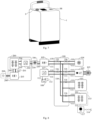
- the system of range extension allows its realization in dimensions and weight that enable its easy transport and installation in the vehicle, for example in its trunk, as can be observed in the implementation method illustrated in Figure 7 .
- the present invention enables the instantaneous use of the total energy available in the range extension batteries, which can be used as emergency batteries. In this way, the vehicle can be used immediately after connection to the system of the present invention.
- the range extension system for storage devices and electric power supply for electric or hybrid vehicles also comprises a pre-charging circuit, which is configured to allow adaptation between the voltage of the range extension batteries and the voltage of the vehicle's high voltage bus.
- the energy stored in the range extension batteries can be used directly by the devices of the vehicle, including the electric traction motor, excluding the necessity to convert energy from direct current (DC) to alternating current (AC) by an inverter and from alternating current (AC) to direct current (DC) by an onboard charger.
- DC direct current
- AC alternating current
- DC direct current
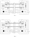
- the present invention refers to a range extension system of electric energy storage and supply devices for electric or hybrid vehicles comprising:
- the external range extension subsystem (1) or the onboard rage extension subsystem (2) include at least one contactor selected from the group consisting of a power contactor for pre-charging and a power contactor for high positive voltage. Additionally, the external range extension subsystem (1) or the onboard range extension subsystem (2) includes at least one pre-charge resistor to ensure adaptation between the voltages observed in the operation of the range extension system of the present invention and the voltages appropriate to the operation of the vehicle modules.
- the first positive high voltage connection (8) includes the first power contactor for pre-charge (16), the first power contactor for positive high voltage (17) and a first pre-charge resistor (19), which are arranged between the range extension battery (5) and the first electrical connection element (3);
- the first negative high voltage connection (9) includes the first power contactor for negative high voltage (18), which is arranged between the range extension battery (5) and the first electrical connection element (3);
- the second positive high voltage connection (10) includes the second power contactor for pre-charge (20), the second power contactor for positive high voltage (21) and a second pre-charge resistor (19), which are arranged between the power distribution module (100) and the second electrical connection element (4);
- the second negative high voltage connection (11) includes the second power contactor for negative high voltage (22), which is arranged between the power distribution module (100) and the second electrical connection element (4);
- a first positive high voltage connection (8) includes a first power contactor for pre-charge (16), a first power contactor for positive high voltage (17) and a first pre-charge resistor (19), and the first negative high voltage connection (9) includes a first power contactor for negative high voltage (18), which are arrange between a range extension battery (5) and a first electrical connection element (3).
- a second positive high voltage connection (10) includes a second power contactor for pre-charge (20), a second power contactor for positive high voltage (21) a second pre-charge resistor (19) and the second negative high voltage connection (11) includes a second power contactor for negative high voltage (22), which are arranged between the power distribution module (100) and the second electrical connection element (4).
- Said power contactor for positive high voltage (17 and 21) are configured to ensure the isolation of high voltage connections, plugs and exposed components of the range extension system, and promote progressive connection after the voltage balance between the system components and the vehicle is reached. The gradual connection initially occurs with the activation of the power contactors for negative high voltage (18 e 22) and the power contactors for pre-charge (16 e 20).
- the pre-charge resistors (19) limit the current in the circuit due to voltage differences between the high voltage bus of the range extender, namely between the first positive high voltage connection (8) and the first negative high voltage connection (9) and the second positive high voltage connection (10) and the second negative high voltage connection (11), protecting components and contacts. Then, the high voltage voltages will tend towards near values and at that instant it will be possible to establish the connection between the high voltage bus, by activating the power contactors for positive high voltage (17 and 21), safely.
- the first electrical connection element (3) and the second electrical connection element (4) are detected by the first range extension control subsystem (6) and by the second range extension control subsystem (7), when the circuit closing on the first electrical contact check connection (12) and second electrical contact check connection (13) occurs.
- the second range extension control subsystem (7) After digital communication between the first digital communications bus (14) and the second digital communications bus (15) and the connection between the external range extension subsystem (1) and the onboard range extension (2), the second range extension control subsystem (7) disables the vehicle's high-voltage batteries by communicating with the battery management unit through a digital communications bus of the vehicle (31).
- the voltage balance is established between the voltage of the range extension battery (5) and the high-voltage components in the vehicle.
- the system of the present invention provides advantages related to an immediate availability stored energy in the range extension battery (5), while it is possible the immediate use of the vehicle, even with the batteries of the vehicle discharged.
- This provides a faster and more efficient recharging process, and it is also possible to extend the vehicle's range, whereby the range extension battery (5) can operate in parallel with the vehicle's high-voltage batteries.
- the system of the present invention comprises a high to low voltage converter (32), which is linked to at least one range extension battery (5) and to the first range extension control subsystem (6), and is configured to provide the electrical supply to low voltage devices.
- a high to low voltage converter 32
- the system of the present invention comprises a high to low voltage converter (32), which is linked to at least one range extension battery (5) and to the first range extension control subsystem (6), and is configured to provide the electrical supply to low voltage devices.
- the second range extension control subsystem (7) is contacted to a digital communications bus of the vehicle (31).
- the system of the present invention comprises a range extension battery loading subsystem (33), which includes a first alternating-to-direct voltage converter (34) and a first battery monitoring and balancing subsystem (35); wherein said first alternating-to-direct voltage converter (34) is configured to connect to at least one range extension battery (5) through a third positive high voltage connection (37) and a third negative high voltage connection (38); and wherein
- the range extension battery loading subsystem (33) can be configured with the possibility of connecting and disconnecting or coupling and uncoupling the range extension system of storage devices and electric power supply for electric or hybrid vehicles with an alternating voltage socket outlet (36), in addition to being configured to manage the range extension battery (5) usage.
- the range extension battery (5) charging will be done by using a first alternating-to-direct voltage converter (34), which converts typically alternating voltages into direct voltages and currents as required to charge the battery and its cells.
- the first battery monitoring and balancing subsystem (35), through connections (39), monitors the state of the range extension battery (5) cells and the relevant voltage and temperature of the range extension battery (5), in addition to controlling the charge parameters of the range extension battery (5) according to the output voltage and current of the first alternating-to-direct voltage converter (34).
- the connections (39) are wire connections to the cells, namely analogue cells, which are configured to measure their voltage and ensure voltage balance.
- the first alternating-to-direct voltage converter (34) can be powered through an alternating voltage socket outlet (36), single-phase or three-phase, or to an electric or hybrid vehicle recharge station (44).
- the first range extension control subsystem (6) comprises a microcontroller (45), a power circuit (46), a power circuit for contactors control (47), a signal adaptation circuit for verifying electrical connections (48) and a module signal adapter for digital communication circuits (49); wherein
- the power circuit for contactors control (47) includes power transistors which enable the contactors to be activated.
- MOSFET Metal Oxide Semiconductor Field Effect Transistor
- a signal adaptation circuit for verifying electrical connections (48) includes signal adapters, which allow impedance and voltage compatibility between the microcontroller's (45) input and output (I/O) port signals and the signals used to detect the presence of the first electrical contact check connection (12).
- the first range extension control subsystem (6) may include a power circuit (46); a microcontroller (45), which executes a code including instructions for the execution of the link control programme between the external range extension subsystem (1) and the onboard range extension subsystem (2).
- the control of the connection between the subsystems (1,2) is through communication between the first range extension control subsystem (6) and the second range extension control subsystem (7), through the connection between the first digital communications bus (14) and the second digital communications bus (15).
- the microcontroller (45) includes a digital communication network controller system, for example a CAN "Controller Area Network" bus and a data input and output ("I/O") module.
- the module signal adapter for digital communication circuits (49) also includes a digital communication network controller system, for example a CAN bus.
- the second range extension control subsystem (7) and the first range extension control subsystem (6) may have similar circuits and components.
- these control subsystems (6,7) have differences with regard to the connection with the battery monitoring and balancing subsystems, since the first range extension control subsystem (6) communicates with the first battery monitoring and balancing subsystem (35), whereas the second range extension control subsystem (7) is connected to a second battery monitoring and balancing subsystem (117) through the digital communications bus of the vehicle (31), as illustrated in figure 6 .
- the power distribution module (100) connects the high-voltage connections from the module of high-voltage batteries (101) and distributes to the other components of the electric or hybrid vehicle.
- the power distribution module (100) is connected to at least one module of high-voltage batteries (101), to a traction system controller of the vehicle (102) configured to actuate in an electric traction motor of the vehicle (103), to a high-voltage charger of the vehicle (105) and with a converter between high and low voltage of the vehicle (107), wherein said connections are carried out respectively through fourth positive high voltage connections (110) and fourth negative high voltage connections (111).
- the module of high-voltage batteries (101) are disabled through the control action of the second range extension control subsystem (7) on the second battery monitoring and balancing subsystem (117), through the digital communications bus of the vehicle (31), and the subsequent communication of the second battery monitoring and balancing subsystem (117) with the module of high-voltage batteries (101), thus allowing the direct supply of another high-voltage system of the vehicle (104), the traction system controller of the vehicle (102) and the converter between high and low voltage of the vehicle (107), between other components.
- the second battery monitoring and balancing subsystem (117) controls at least one the module of high-voltage batteries (101) through a seventh control connection (115). Additionally, the second battery monitoring and balancing subsystem (117) may also feature a digital communication to the bus of the vehicle (114).
- the high-voltage charger of the vehicle (105) is connected to a charge socket outlet of the vehicle (106) through a third alternating voltage connection (109), while preserving the possibility of connecting the vehicle with an electric or hybrid vehicle recharge station (44).
- the converter between high and low voltage of the vehicle (107) is connected with a low-voltage battery in the vehicle (108), through a positive low voltage connection (112), whereby the low-voltage battery in the vehicle (108) is simultaneously connected with a negative low-voltage connection (113).
- the connections between the power distribution module (100) and the module of high-voltage batteries (101), the traction system controller of the vehicle (102), the high-voltage charger of the vehicle (105) and the converter between high and low voltage of the vehicle (107) includes at least one high voltage fuse (116), configured for the protection of the respective connections against overvoltage. Even more preferably, said high voltage fuse (116) can be included in the power distribution module (100).
- the range extension system can work permanently on the electric or hybrid vehicle, maintaining the first electrical connection element (3) and the second electrical connection element (4) connected, and the first power contactor for positive high voltage (17), the first power contactor for negative high voltage (18), the second power contactor for positive high voltage (21) and the second power contactor for negative high voltage (22) permanently activated.
- the range extension system of the invention enables the increase of the module of high-voltage batteries (101) capacity in the vehicle and, as a result, their autonomy.
- the charging of the range extension battery (5) will be done by the high-voltage charger of the vehicle (105).
- the range extension system of the invention allows its implementation in dimensions and weight that provides its easy transport and installation in the vehicle, for example in its boot, as can be observed in the implementation method illustrated in figure 7 , which presents an embodiment in which the external range extension subsystem (1) is incorporated in a transportable unit including a carrying handle and wheels on its base, where the terminals of the first electrical connection element (3) and the alternating voltage socket outlet (36) are arranged in order to provide the respective connections.
- low voltage comprises a standard voltage of 12V for light vehicles and a standard voltage of 24V for heavy vehicles.
- high voltage comprises higher voltages than low voltage referring to the battery storing energy, for which no specific standards are defined.
- the precise value depends on the vehicle power and the number of cells used, the most typical being 48V, 96V, 100V, 300V, 350V, 400V, 600V and 800V, but values are not limited to these examples.
- the term "or” is intended to mean an inclusive “or” rather than an exclusive “or.” That is, unless specified otherwise, or clear from the context, the phrase “X employs A or B” is intended to mean any of the natural inclusive permutations. That is, the phrase “X employs A or B” is satisfied by any of the following instances: X employs A; X employs B; or X employs both A and B.
- exemplary is intended to mean serving as an illustration or example of something and is not intended to indicate a preference.
- the expression “substantially” means that the real value is within around 10% of the desired value, variable, or related limit, particularly within around 5% of the desired value, variable or related limit or particularly within around 1% of the desired value, variable or related limit.
Landscapes
- Engineering & Computer Science (AREA)
- Power Engineering (AREA)
- Transportation (AREA)
- Mechanical Engineering (AREA)
- Life Sciences & Earth Sciences (AREA)
- Sustainable Development (AREA)
- Sustainable Energy (AREA)
- Charge And Discharge Circuits For Batteries Or The Like (AREA)
- Electric Propulsion And Braking For Vehicles (AREA)
Applications Claiming Priority (1)
| Application Number | Priority Date | Filing Date | Title |
|---|---|---|---|
| PT117569A PT117569A (pt) | 2021-11-10 | 2021-11-10 | Sistema de extensão da autonomia de dispositivos de armazenagem e de fornecimento de energia elétrica para veículos elétricos ou híbridos |
Publications (1)
| Publication Number | Publication Date |
|---|---|
| EP4180263A1 true EP4180263A1 (de) | 2023-05-17 |
Family
ID=85937979
Family Applications (1)
| Application Number | Title | Priority Date | Filing Date |
|---|---|---|---|
| EP22166987.2A Pending EP4180263A1 (de) | 2021-11-10 | 2022-04-06 | System zur erweiterung der reichweite von elektrischen energiespeicher- und -versorgungsvorrichtungen für elektro- oder hybridfahrzeuge |
Country Status (2)
| Country | Link |
|---|---|
| EP (1) | EP4180263A1 (de) |
| PT (1) | PT117569A (de) |
Cited By (1)
| Publication number | Priority date | Publication date | Assignee | Title |
|---|---|---|---|---|
| EP4545338A1 (de) * | 2023-10-24 | 2025-04-30 | Thermo King LLC | Verfahren zur schnittstellenbildung zwischen einem elektrischen hilfssystem und einem elektrischen energienetz eines fahrzeugs |
Citations (4)
| Publication number | Priority date | Publication date | Assignee | Title |
|---|---|---|---|---|
| JP2003169401A (ja) * | 2001-11-30 | 2003-06-13 | Sanyo Electric Co Ltd | 漏電検出回路を備える電動車両の電源装置 |
| US10737583B2 (en) * | 2011-05-10 | 2020-08-11 | Stephen G. Johnsen | Mobile variable power system and method |
| US11077760B2 (en) * | 2019-02-26 | 2021-08-03 | Ford Global Technologies, Llc | Precharging for direct current fast charging |
| US11142092B2 (en) * | 2019-03-06 | 2021-10-12 | Toyota Jidosha Kabushiki Kaisha | Power supply system for vehicle |
Family Cites Families (10)
| Publication number | Priority date | Publication date | Assignee | Title |
|---|---|---|---|---|
| DE102008006332A1 (de) * | 2008-01-27 | 2009-07-30 | M200 Gmbh | Anhänger-Range-Extender für Elektrofahrzeuge, Hybridfahrzeuge und Plug-In-Hybridfahrzeuge |
| US9457666B2 (en) * | 2012-03-30 | 2016-10-04 | Elwha Llc | Method and apparatus for supplying auxiliary electrical power to an electric or hybrid vehicle |
| DE102012011960A1 (de) * | 2012-06-18 | 2013-12-19 | Bvb Innovate Gmbh | Einbausatz für Elektrofahrzeuge und anhängerbasierter Range-Extender zur Reichweitenverlängerung |
| KR101393275B1 (ko) * | 2012-09-25 | 2014-05-12 | 자동차부품연구원 | 모듈 확장형 배터리 시스템 |
| US9802558B2 (en) * | 2013-09-27 | 2017-10-31 | GM Global Technology Operations LLC | Distributed vehicle battery high-voltage bus systems and methods |
| CN103640493A (zh) * | 2013-12-17 | 2014-03-19 | 奇瑞汽车股份有限公司 | 一种电动汽车增程系统 |
| CN106740155B (zh) * | 2015-11-20 | 2019-07-16 | 通用电气公司 | 增程器、能量管理系统及能量管理方法 |
| CN108248397A (zh) * | 2016-12-29 | 2018-07-06 | 比亚迪股份有限公司 | 发电控制方法、装置、增程器系统及电动汽车 |
| KR102256097B1 (ko) * | 2017-11-29 | 2021-05-25 | 주식회사 엘지에너지솔루션 | 배터리 팩 |
| CN212332392U (zh) * | 2020-04-16 | 2021-01-12 | 郎忠孝 | 一种新能源汽车增程应急电源 |
-
2021
- 2021-11-10 PT PT117569A patent/PT117569A/pt unknown
-
2022
- 2022-04-06 EP EP22166987.2A patent/EP4180263A1/de active Pending
Patent Citations (4)
| Publication number | Priority date | Publication date | Assignee | Title |
|---|---|---|---|---|
| JP2003169401A (ja) * | 2001-11-30 | 2003-06-13 | Sanyo Electric Co Ltd | 漏電検出回路を備える電動車両の電源装置 |
| US10737583B2 (en) * | 2011-05-10 | 2020-08-11 | Stephen G. Johnsen | Mobile variable power system and method |
| US11077760B2 (en) * | 2019-02-26 | 2021-08-03 | Ford Global Technologies, Llc | Precharging for direct current fast charging |
| US11142092B2 (en) * | 2019-03-06 | 2021-10-12 | Toyota Jidosha Kabushiki Kaisha | Power supply system for vehicle |
Non-Patent Citations (1)
| Title |
|---|
| TU-DELFT: "Electric cars: Technology", 15 March 2010 (2010-03-15), pages 1 - 14, XP055921022, Retrieved from the Internet <URL:https://ocw.tudelft.nl/wp-content/uploads/eCARS2x_Lecture_Notes_L3-3.pdf> [retrieved on 20220513] * |
Cited By (1)
| Publication number | Priority date | Publication date | Assignee | Title |
|---|---|---|---|---|
| EP4545338A1 (de) * | 2023-10-24 | 2025-04-30 | Thermo King LLC | Verfahren zur schnittstellenbildung zwischen einem elektrischen hilfssystem und einem elektrischen energienetz eines fahrzeugs |
Also Published As
| Publication number | Publication date |
|---|---|
| PT117569A (pt) | 2023-05-10 |
Similar Documents
| Publication | Publication Date | Title |
|---|---|---|
| US11447031B2 (en) | Electric vehicle charging apparatus | |
| EP3800083B1 (de) | Stromversorgungs- und wiederaufladegruppen eines elektrofahrzeugs und verfahren dafür | |
| US10052967B2 (en) | Electric voltage system and method for distributing electrical power in an electric voltage system | |
| CN115298056B (zh) | 电动车辆充电控制器及包括该电动车辆充电控制器的电动车辆充电器 | |
| US9227517B2 (en) | Charging device having a bidirectional auxiliary power supply unit | |
| CN106585421B (zh) | 一种电动汽车智能充电装置 | |
| US11285841B2 (en) | Multi-voltage battery device and onboard electrical system for a motor vehicle | |
| US9755443B2 (en) | Safety concept for batteries | |
| CN107206906A (zh) | 用于机动车的高压电池以及机动车 | |
| US20210028642A1 (en) | Electrical energy storage system and method for operating same | |
| US9306403B2 (en) | Battery module, battery management system, system for supplying a drive of a machine suitable for generating torque with electrical energy, and a motor vehicle | |
| CN114228562A (zh) | 动力电池充放电管理系统及其方法 | |
| CN115902687A (zh) | 用于能量存储系统的接地故障监测系统 | |
| CN117500684A (zh) | 用于执行车辆的车载电网的预充电过程的方法和用于车辆的车载电网 | |
| CN204559137U (zh) | 一种纯电动车直流充电互锁控制电路 | |
| US11491886B2 (en) | DC voltage charging post for charging an electric vehicle | |
| CN110450675B (zh) | 一种动力电池系统、控制方法和电动汽车 | |
| CN209257888U (zh) | 电池充电装置及系统 | |
| EP4035922B1 (de) | Verteiltes bordstromversorgungssystem und verfahren und gerät zur steuerung der bordstromversorgung | |
| WO2026001981A1 (zh) | 电池包、并网管理方法、电能设备以及储能系统 | |
| CN216153589U (zh) | 一种交直流充电装置及车辆 | |
| CN107706997A (zh) | 智能均衡配电设备、智能均衡配电系统和复合能源系统 | |
| US11180047B2 (en) | Method for testing a charging process | |
| CN117774690A (zh) | 一种用于储能系统和新能源汽车的配电盒和配电系统 | |
| US11545834B1 (en) | Balancing power from electric vehicle in vehicle-to-building supply |
Legal Events
| Date | Code | Title | Description |
|---|---|---|---|
| PUAI | Public reference made under article 153(3) epc to a published international application that has entered the european phase |
Free format text: ORIGINAL CODE: 0009012 |
|
| STAA | Information on the status of an ep patent application or granted ep patent |
Free format text: STATUS: REQUEST FOR EXAMINATION WAS MADE |
|
| 17P | Request for examination filed |
Effective date: 20220901 |
|
| AK | Designated contracting states |
Kind code of ref document: A1 Designated state(s): AL AT BE BG CH CY CZ DE DK EE ES FI FR GB GR HR HU IE IS IT LI LT LU LV MC MK MT NL NO PL PT RO RS SE SI SK SM TR |