EP4180252A1 - Ventilator - Google Patents
Ventilator Download PDFInfo
- Publication number
- EP4180252A1 EP4180252A1 EP21836862.9A EP21836862A EP4180252A1 EP 4180252 A1 EP4180252 A1 EP 4180252A1 EP 21836862 A EP21836862 A EP 21836862A EP 4180252 A1 EP4180252 A1 EP 4180252A1
- Authority
- EP
- European Patent Office
- Prior art keywords
- airflow
- flow path
- louver
- airflow direction
- convex part
- Prior art date
- Legal status (The legal status is an assumption and is not a legal conclusion. Google has not performed a legal analysis and makes no representation as to the accuracy of the status listed.)
- Granted
Links
Images


Classifications
-
- F—MECHANICAL ENGINEERING; LIGHTING; HEATING; WEAPONS; BLASTING
- F24—HEATING; RANGES; VENTILATING
- F24F—AIR-CONDITIONING; AIR-HUMIDIFICATION; VENTILATION; USE OF AIR CURRENTS FOR SCREENING
- F24F13/00—Details common to, or for air-conditioning, air-humidification, ventilation or use of air currents for screening
- F24F13/08—Air-flow control members, e.g. louvres, grilles, flaps or guide plates
- F24F13/10—Air-flow control members, e.g. louvres, grilles, flaps or guide plates movable, e.g. dampers
- F24F13/14—Air-flow control members, e.g. louvres, grilles, flaps or guide plates movable, e.g. dampers built up of tilting members, e.g. louvre
- F24F13/1413—Air-flow control members, e.g. louvres, grilles, flaps or guide plates movable, e.g. dampers built up of tilting members, e.g. louvre using more than one tilting member, e.g. with several pivoting blades
-
- B—PERFORMING OPERATIONS; TRANSPORTING
- B60—VEHICLES IN GENERAL
- B60H—ARRANGEMENTS OF HEATING, COOLING, VENTILATING OR OTHER AIR-TREATING DEVICES SPECIALLY ADAPTED FOR PASSENGER OR GOODS SPACES OF VEHICLES
- B60H1/00—Heating, cooling or ventilating devices
- B60H1/34—Nozzles; Air-diffusers
- B60H1/3414—Nozzles; Air-diffusers with means for adjusting the air stream direction
- B60H1/3421—Nozzles; Air-diffusers with means for adjusting the air stream direction using only pivoting shutters
-
- F—MECHANICAL ENGINEERING; LIGHTING; HEATING; WEAPONS; BLASTING
- F24—HEATING; RANGES; VENTILATING
- F24F—AIR-CONDITIONING; AIR-HUMIDIFICATION; VENTILATION; USE OF AIR CURRENTS FOR SCREENING
- F24F13/00—Details common to, or for air-conditioning, air-humidification, ventilation or use of air currents for screening
- F24F13/08—Air-flow control members, e.g. louvres, grilles, flaps or guide plates
- F24F13/10—Air-flow control members, e.g. louvres, grilles, flaps or guide plates movable, e.g. dampers
- F24F13/14—Air-flow control members, e.g. louvres, grilles, flaps or guide plates movable, e.g. dampers built up of tilting members, e.g. louvre
- F24F13/142—Air-flow control members, e.g. louvres, grilles, flaps or guide plates movable, e.g. dampers built up of tilting members, e.g. louvre using pivoting blades with intersecting axles
-
- B—PERFORMING OPERATIONS; TRANSPORTING
- B60—VEHICLES IN GENERAL
- B60H—ARRANGEMENTS OF HEATING, COOLING, VENTILATING OR OTHER AIR-TREATING DEVICES SPECIALLY ADAPTED FOR PASSENGER OR GOODS SPACES OF VEHICLES
- B60H1/00—Heating, cooling or ventilating devices
- B60H1/34—Nozzles; Air-diffusers
- B60H2001/3464—Details of hinges
-
- B—PERFORMING OPERATIONS; TRANSPORTING
- B60—VEHICLES IN GENERAL
- B60H—ARRANGEMENTS OF HEATING, COOLING, VENTILATING OR OTHER AIR-TREATING DEVICES SPECIALLY ADAPTED FOR PASSENGER OR GOODS SPACES OF VEHICLES
- B60H1/00—Heating, cooling or ventilating devices
- B60H1/34—Nozzles; Air-diffusers
- B60H2001/3471—Details of actuators
Definitions
- the present invention relates to a ventilator.
- JP5597423B disclosed is an air conditioning register comprising a first inclined surface that is inclined to expand facing a vehicle compartment at the top and bottom of an opening part, and fins that are provided inside the opening part and that changes the blowing direction of the vertical direction air by adjusting the vertical direction inclination angle.
- the inventor of the present application found that the phenomenon of a portion of the air blowing from the opening part when the air conditioning register is blowing air facing downward flowing along a first inclined surface of the upper side (specifically, facing upward) is based on the arrangement of ridges with respect to the fins. Specifically, the inventor of the present application surmised that the phenomenon noted above is caused by the airflow facing the air conditioning register from the duct clinging to the first inclined surface due to the Coanda effect when it passes over the ridges.
- the arrangement of the ridges is determined by the design of the air conditioning register.
- the design of the air conditioning register for example, a design is conceivable in which the ridges are at a deep position in the upstream side of the airflow direction inside the air conditioning register, and a first inclined surface extends more toward the downstream side from the upstream side in the airflow direction inside the air condition register compared to the fins.
- Such a design becomes a design that gives a high grade feel with a sense of depth by having the first inclined surface as a design part penetrate the inside of the air conditioning register.
- this design has the problem of the Coanda effect easily occurring because the airflow that faces the air conditioning register from the duct passes directly over the ridges.
- the purpose of the present invention is to suppress the occurrence of the Coanda effect on a member in a ventilator in which the member that forms a portion of an opening part is inclined so that the opening area of the opening part widens facing from the upstream side to the downstream side of the airflow direction.
- a ventilator in which airflow passes through a flow path and is blown from an opening part comprises: a first louver on which a knob is mounted; a plurality of second louvers that are provided in a direction intersecting the first louver, and that are arranged at the upstream side in the airflow direction from the first louver; a pair of side walls that support the first louver to be able to rotate, and that form a portion of the opening part; and a first inclined member that forms another portion of the opening part between the pair of side walls, and that is inclined so that the opening area of the opening part widens facing the downstream side from the upstream side of the airflow direction.
- the first inclined member has the vertex of the incline positioned at the upstream side of the airflow direction.
- the upstream end part is positioned at the downstream side in the airflow direction from the vertex of the upstream side in airflow direction of the first inclined member, or at the same position in the airflow direction.
- the ventilator further comprises a convex part arranged adjacent to the vertex at the upstream side in the airflow direction. In the direction orthogonal to both the rotation axis of the first louver and the airflow direction, the convex part projects further to the inside of the flow path than the vertex, and is provided to extend across the plurality of second louvers seen from the airflow direction.
- FIG. 1 is a front view of the ventilator 100.
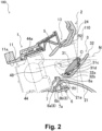
- FIG. 2 is a schematic diagram of the cross section when the ventilator 100 of FIG. 1 blows the airflow furthest upward, and is a schematic diagram corresponding to cross section II-II of FIG. 1 .
- FIG. 3 is a schematic diagram of cross section III-III of FIG. 1 .
- FIG. 4 is a schematic diagram of cross section IV-IV of FIG. 3 .
- the paper surface vertical direction is the vertical direction of the ventilator 100.
- the paper surface lateral direction is the lateral direction of the ventilator 100.
- the paper surface vertical direction is the airflow direction of the ventilator 100.
- the paper surface left side is the upstream side of the airflow direction in the ventilator 100.
- the paper surface right side is the downstream side of the airflow direction in the ventilator 100.
- the paper surface upper side is the upstream side of the airflow direction in the ventilator 100.
- the paper surface lower side is the downstream side of the airflow direction in the ventilator 100.
- the ventilator 100 is for vehicles, and for example is provided in the instrument panel, center cluster, etc., of a vehicle compartment.
- the ventilator 100 guides air for which temperature and humidity have been adjusted by an air conditioning device (not illustrated) inside the vehicle compartment.
- the ventilator 100 comprises a flow path member 1 (also called a housing or case), a bezel part 2, a first louver unit 3, and a second louver unit 4.
- the flow path member 1 is an approximately cylindrically shaped member. As shown in FIG. 3 , an inflow port 12 and an outflow port 13 open at both ends of the flow path member 1.
- a flow path 11 (space through which air flows) through which airflow can pass is formed inside the flow path member 1.
- a duct (not illustrated) is connected to the inflow port 12. The airflow sent from the air conditioning device via the duct to the flow path 11 flows in from the inflow port 12. The airflow that flowed into the flow path 11 flows inside the flow path 11, and flows out from the outflow port 13 to the bezel part 2.
- the direction of the airflow that flows from upstream to downstream as a whole in the flow path 11 interior is called the "airflow direction.”
- the "airflow direction” is the extension direction of the flow path 11, or is the direction parallel to an inner wall 11a of the flow path 11. Details of the airflow are described later.
- the bezel part 2 is a part provided at the outflow port 13 side, and is a part that forms an opening part 110 that blows air in the ventilator 100.
- the bezel part 2 comprises a first inclined member 21, a pair of side walls 22, 23, and an interior panel 24.
- the first inclined member 21 is a member that forms a portion of the opening part 110 (partitions a portion of the contour of the opening part 110).
- the first inclined member 21 is arranged at a position at the lower side in the opening part 110.
- the first inclined member 21 is a member of a shape that is inclined so that the opening area of the opening part 110 widens toward the downstream side from the upstream side of the airflow direction inside the ventilator 100 with the surface starting from a vertex 21a.
- An inclination angle R1 which is the angle between the tangent near the vertex 21a of the first inclined member 21 and the airflow direction (also called the direction when the air flows straight toward the opening part 110 from the inflow port 12; in FIG.
- the Coanda effect in which the airflow clings to the surface of the first inclined member 21, occurs easily (0 degrees ⁇ R1 ⁇ 40 degrees).
- the Coanda effect occurs particularly easily when the inclination angle R1 is in the range of 0 degrees ⁇ R1 ⁇ 30.
- the Coanda effect occurs markedly most easily when the inclination angle R1 is 24 degrees.
- the first inclined member 21 forms the bottom part in the opening part 110.
- the ventilator 100 is arranged below the position of the eye of an occupant inside the vehicle compartment. For that reason, when the occupant views the ventilator 100, the bottom part of the opening part 110 is easy to see.
- the first inclined member 21 of the present embodiment is a decorative plate (finisher) that the occupant sees inside the vehicle compartment.
- the first inclined member 21 that also functions as a decorative plate penetrate to the back of the opening part 110 (in the range at which the first inclined member 21 at least faces a vertical louver 31) with a gentle incline, a design with a sense of depth in which the decorative plate penetrates the interior of the ventilator 100 is achieved. As a result, it is possible to give the occupant an impression of a highquality sense. As shown in FIG. 1 , with the present embodiment, the first inclined member 21 extends in the width direction beyond the opening part 110 (lateral direction in FIG. 1 ).
- the pair of side walls 22, 23 are members that partition the lateral direction of the opening part 110. Specifically, the pair of side walls 22, 23 form a portion of the opening part 110. As shown in FIG. 3 , bearing parts 22a, 23a for supporting the vertical louver 31 described later are provided on the pair of side walls 22, 23.
- the pair of side walls 22, 23 may also be shaped to imitate the vertical louver 31 such as is disclosed in the specification of European Patent Application Publication No. 0289065 ( EP0289065A1 ).
- EP0289065A1 European Patent Application Publication No. 0289065
- the interior panel 24 is a member arranged at a position above the first inclined member 21, and that faces the first inclined member 21.
- the interior panel 24 is a member that is shaped at an inclination angle that is different from the inclination angle R1 of the first inclined member 21, and that is inclined so that the opening area of the opening part 110 widens facing the downstream side from the upstream side of the airflow direction.
- An inclination angle R2 which is the angle between the vicinity of the starting point of the inclination at the upstream side of the airflow direction in the interior panel 24 and the airflow direction (line shown by a dashed line in FIG. 2 ) is 40 degrees or greater.
- the interior panel 24 forms the opening part 110 together with the first inclined member 21 and the pair of side walls 22, 23. Said another way, the opening part 110 is formed by the first inclined member 21, the pair of side walls 22, 23, and the interior panel 24.
- the interior panel 24 is a decorative plate (finisher) seen by the occupant inside the vehicle compartment, and has the same or different decoration implemented to that of the first inclined member 21.
- the first louver unit 3 has the vertical louver 31 as the first louver, a knob 32, and a fork member 33.
- the vertical louver 31 is an approximately plate-shaped member. As shown in FIG. 3 , the vertical louver 31 has a width L1 formed to be approximately the same as the width of the opening part 110. Also, in the vertical louver 31, a length L2 (airflow direction length) is formed to be a level at which when the vertical louver 31 is rotating, it does not interfere with the inner wall 11a of the flow path 11, the inner wall of the outflow port 13, or the inner wall of the opening part 110, etc.
- the vertical louver 31 is arranged inside the opening part 110 by being supported by the pair of side walls 22, 23.
- Shaft parts 3 1a, 3 1b of the vertical louver 31 are rotation shafts, and are supported by the side walls 22, 23.
- the vertical louver 31 can rotate in the vertical direction of the ventilator 100 centered on the rotation center O shown in FIG. 2 .
- the knob 32 is a member mounted on the vertical louver 31.
- the knob 32 is mounted to be able to slide in the lateral direction (width L1 direction of the vertical louver 31 shown in FIG. 3 ) of the ventilator 100.
- the vertical louver 31 rotates in the vertical direction of the ventilator 100 centered on the shaft parts 31a, 31b
- the knob 32 rotates in the vertical direction of the ventilator 100 together with the vertical louver 31 (see FIG. 2 ).
- the shaft part 32a of the knob 32 is the end part at the upstream side in the airflow direction of the knob 32.
- the end part 32b is the end part closest to the first inclined member 21 in the maximum angle state (details are described later) shown in FIG. 2 .
- the knob 32 is mounted to be able to slide on the lower surface (surface facing the first inclined member 21) of the vertical louver 31, so the knob 32 exists partially between the vertical louver 31 and the first inclined member 21.
- the knob 32 may also be mounted on the vertical louver 31 to wrap around the outer periphery of the vertical louver 31 in the cross section of FIG. 2 .
- the vertical louver 31 and the knob 32 rotate centered on the rotation axis.
- the vertical louver 31 changes up and down of the airflow direction flowing from the air conditioning device according to the arrangement within the maximum rotation range which is the range in which rotation is possible.
- the angle of the vertical louver 31 when the ventilator 100 blows the airflow furthest upward is called the “maximum angle,” and the state of the vertical louver 31 at that time is called the “maximum angle state” (see FIG. 2 ).
- the maximum angle state is the angle at which an upstream end part 31c at the upstream side in the airflow direction of the vertical louver 31 is closest to the first inclined member 21.
- the end part closest to the first inclined member 21 in the vertical louver 31 in the maximum angle state is called a proximal end part 31d.
- the upstream end part 31c and the proximal end part 31d are at different locations, but they may also be at the same location. Specifically, in the maximum angle state, the upstream end part 31c may be at the location closest to the first inclined member 21 of the vertical louver 31.
- the angle of the vertical louver 31 when the ventilator 100 blows the airflow furthest downward is called the "reverse maximum angle”
- the state of the vertical louver 31 at that time is called the “reverse maximum angle state” (see FIG. 6 described later).
- the angle of the vertical louver 31 that is parallel to the inner wall 1 1a of the flow path 11 is called the “reference angle.”
- the reference angle is the angle when the ventilator 100 blows air toward the neck of the occupant when an occupant of a prescribed height (e.g., 175 cm) is seated.
- the state when the vertical louver 31 is at the reference angle is called the "reference state.”
- the reference angle is shown by the single-dash line N. In FIG. 2 , it looks like there is an angle between the line N and the inner wall 1 1a of the flow path 11, but in the reference state, both items are actually parallel.
- the fork member 33 is linked to the end part at the upstream side of the airflow direction of the knob 32.
- the knob 32 and the fork member 33 are connected via a pin 34.
- a pin member 48 of the second louver unit 4 described later is fitted between projections 33a, 33b of the fork member 33.
- the second louver unit 4 has lateral louvers 41 to 46 as a plurality of second louvers, a link member 47, and the pin member 48. As shown in FIG. 3 , the second louver unit 4 is arranged further to the upstream side in the airflow direction than the first louver unit 3 inside the flow path 11.
- the plurality of lateral louvers 41 to 46 are linked with the link member 47 interposed.
- the lateral louvers 41 to 46 are provided in the direction intersecting the vertical louver 31, and are arranged further to the upstream side in the airflow direction than the vertical louver 31.
- the lateral louvers 41 to 46 rotate in the lateral direction in FIG. 1 centered on a prescribed shaft part (in FIG. 2 , lateral louver 44 and a shaft part 44a of the lateral louver 44 are shown).
- the lateral louver 44 closest to the space between the projections 33a, 33b of the fork member 33 has the pin member 48 provided for connecting the second louver unit 4 and the fork member 33 (see FIG. 1 to FIG. 4 ).
- the pin member 48 rotates in the lateral direction of the ventilator 100 together with that.
- the lateral louvers 41 to 46 tilt toward the rotation direction of the pin member 48 (specifically, the lateral direction of the ventilator 100).
- the lateral louvers 41 to 46 change the lateral flow direction of the airflow that flows from the air conditioning device according to the inclination state.
- an auxiliary vertical louver 5 is provided in the flow path 11 inside the flow path member 1.
- the auxiliary vertical louver 5 is linked to the vertical louver 31 via a connecting member 51 (see FIG. 1 ).
- the auxiliary vertical louver 5 rotates in the same direction as the vertical louver 31 and the knob 32 in accordance with rotation of the vertical louver 31 and the knob 32 in the vertical direction of the ventilator 100.
- the auxiliary vertical louver 5 changes the vertical flow direction of the air flowing from the air conditioning device.
- a convex member 6 and a guide member 7 are arranged inside the flow path 11 of the flow path member 1.
- the vertex 21a is at the location at which the opening area of the opening part 110 is narrowest in the first inclined member 21. Also, the vertex 21a is the end part at the upstream side in the airflow direction. Specifically, the vertex 21a is the part closest to the outflow port 13 of the flow path member 1 of the first inclined member 21.
- the vertex 21a is arranged further to the upstream side in the airflow direction than the upstream end part 31c of the vertical louver 31 in the maximum angle state.
- the convex member 6 is arranged at a position adjacent to the vertex 21a of the first inclined member 21 at the upstream side in the airflow direction.
- the convex member 6 has a convex part 6a and a second inclined part 6b.
- the convex part 6a is provided extending across all the lateral louvers 41 to 46 seen from the airflow direction.
- the convex part 6a is a part projecting more to the inside of the flow path 11 than the vertex 21a.
- the inside of the flow path 11 is the side facing the direction separating from the inner circumference surface that forms the flow path 11 of the flow path member 1, specifically, the side facing the position of the first louver unit 3 in the reference state shown by the two-dot-dash line in FIG. 2 from the inner wall 11a of the lower side of the flow path member.
- the convex part 6a can be said to be projecting toward the inside of the flow path 11 in the direction orthogonal to both the rotation axis direction of the vertical louver 31 and the airflow direction (specifically, approximately the vertical direction in FIG. 2 ).
- the convex part 6a may also be provided extending across a portion of the lateral louvers 41 to 46 (plurality of lateral louvers among the lateral louvers 41 to 46) seen from the airflow direction.
- the convex part 6a projects upward from the proximal end part 31d of the vertical louver 31 in the maximum angle state (height is higher) in the direction orthogonal to both the rotation axis direction of the vertical louver 31 and the airflow direction (specifically, approximately the vertical direction in FIG. 2 ). Furthermore, the convex part 6a is arranged between the vertical louver 31 and the lateral louvers 41 to 46 in the airflow direction.
- the convex part 6a projects 3 mm more than the vertex 21a.
- the convex part 6a projects 3 mm or more from the vertex 21a in the direction noted above in a range in which the first louver unit 3 does not reach the rotation orbit from the reference state to the maximum angle state (arc-shaped double-dot-dash line that connects the position of the end part 32a shown by the solid line in FIG. 2 and the end part 32a shown by the double-dot-dash line in FIG. 2 ).
- the second inclined part 6b is an inclined plane that is positioned further to the upstream side in the airflow direction than the convex part 6a, and that is inclined to face the inside of the flow path 11 facing the downstream side from the upstream side of the airflow direction.
- the guide member 7 is arranged further to the upstream side in the airflow direction than the convex member 6. Also, the guide member 7 has a second convex part 7a.
- the second convex part 7a projects more toward the inside of the flow path 11 than the proximal end part 31d in the direction orthogonal to both the rotation axis direction of the vertical louver 31 and the airflow direction (specifically, approximately the vertical direction with respect to FIG. 2 ).
- the second convex part 7a projects facing more to the inside of the flow path 11 than the convex part 6a.
- the second convex part 7a is provided extending across all of the lateral louvers 41 to 46 seen from the airflow direction, but it is also possible to be provided extending across a portion of the lateral louvers 41 to 46) (a plurality of lateral louvers of the lateral louvers 41 to 46) seen from the airflow direction.
- the guide member 7 forms a guide flow path 8 together with the convex member 6.
- the guide flow path 8 is formed so that the flow path cross section area of an outlet 8b is smaller than the flow path cross section area of an inlet 8a.
- FIG. 5 is a schematic diagram of the cross section when airflow is blown furthest upward by the ventilator 100, and is a drawing correlating to the II-II cross section in FIG. 1 .
- FIG. 6 is a schematic diagram of the cross section when the ventilator 100 is blowing airflow furthest downward, and is a drawing correlating to the II-II cross section in FIG. 1 .
- FIG. 9 is a schematic diagram of the cross section of a ventilator 200 of a comparison example, and is a drawing correlating to the II-II cross section of FIG. 1 .
- the flow of air flowing in the ventilators 100, 200 is shown by arrows A to K.
- the first louver unit 3 and the auxiliary vertical louver 5 are at the maximum angle state, and are inclined to face more upward the more downstream the airflow direction faces.
- the airflow sent from the air conditioning device flows into the flow path 11 from the inflow port 12 of the flow path member 1.
- the airflow that flows into the flow path 11 can be roughly divided into the airflow that flows to the upper side of the flow path 11 as shown by arrow A (the paper surface upward side in FIG. 2 of the flow path 11, specifically, the side in which the auxiliary vertical louver 5 is arranged), the airflow that flows to inside the flow path 11 as shown by arrow B (the paper surface center side in FIG. 2 of the flow path 11, specifically, the side nearest the pin member 48), and the airflow that flows to the lower side of the flow path 11 as shown by arrow C and arrow D (the paper surface lower side in FIG. 2 of the flow path 11, the side in which the convex member 6 and the guide member 7 are arranged).
- arrow A the paper surface upward side in FIG. 2 of the flow path 11, specifically, the side in which the auxiliary vertical louver 5 is arranged
- arrow B the paper surface center side in FIG. 2 of the flow path 11, specifically, the
- the airflow that flows to the upper side of the flow path 11 flows inside the flow path 11 as shown by arrow A. Specifically, the airflow that flows to the upper side of the flow path 11 first flows facing the extension direction of the flow path 11 (said another way, to the direction parallel to the inner wall 11a of the flow path 11). Thereafter, that airflow has the flow changed to the upward side of the ventilator 100 by the auxiliary vertical louver 5, and is blown facing upward from the outflow port 13 and the opening part 110.
- the airflow that flows to the lower side of the flow path 11 flow insides the flow path 11 as shown by the arrow C or arrow D.
- the airflow that flows to the lower side of the flow path 11 can be divided into cases of not passing through the guide flow path 8 as shown by arrow C and cases of passing through the guide flow path 8 as shown by arrow D.
- the convex part 6a projects more greatly than the proximal end part 31d of the vertical louver 31, so in the maximum angle state, direct flowing of the airflow facing between the first inclined member 21 and the vertical louver 31 is suppressed. Also, even if a portion of the airflow merged with the airflow of arrow C and arrow B wraps around to bypass the convex part 6a, first, as noted above, clinging of the airflow near the vertex 21a is suppressed. Furthermore, the first inclined member 21 is inclined downward facing the downstream side of the airflow direction. Thus, since the first inclined member 21 is inclined downward facing the downstream side of the airflow direction, a portion of that airflow touching the surface of the first inclined member 21 is suppressed.
- the "adjacent" range between the convex part 6a and the vertex 21a refers to the distance between the vertex 21a and the convex part 6a in the range in which the airflow that passes over the convex part 6a does not wrap around the vertex 21a, and means that the distance from the vertex 21a to the convex part 6a is approximately 3 mm or less. Provided the distance from the vertex 21a to the second convex part 7a is 3 mm or less, the second convex part 7a and the vertex 21a can be understood as being adjacent.
- the airflow facing the first louver unit 3 is guided to flow upward by the first louver unit 3, and is blown from the outflow port 13 and the opening part 110 facing upward.
- the guide flow path 8 is formed so that the flow path cross section area of the outlet 8b is smaller than the flow path cross section area of the inlet 8a. Specifically, the guide flow path 8 is formed so that the outlet 8b is narrower than the inlet 8a. For that reason, the guide flow path 8 is able to speed up the flow speed of the air flowing in the guide flow path 8 at the outlet side, causing the airflow to flow out vigorously from the outlet 8b.
- the airflow for which the flow speed became faster and the flow changed to upward by passing through the guide flow path 8 merges with the airflow of arrow B as shown by arrow D, and flows toward the vertical louver 31 of the first louver unit 3.
- the airflow blown from the outlet 8b has a faster flow speed as noted above, so exhibits an effect of pushing the airflow of arrow B to face the upper side.
- the air flowing to inside the flow path 11 flows inside the flow path 11 as shown by arrow B. Specifically, the airflow that flows to inside the flow path 11 first flows facing the extension direction of the flow path 11. After that, that airflow merges with the air flowing facing upward from the lower surface inside the flow path 11 (airflow of the flow of arrow C and arrow D), and the flow changes to the upward side of the ventilator 100. Also, by the airflow contacting the vertical louver 31, the airflow direction changes, flowing facing the upward side along the vertical louver 31, and is blown from the outflow port 13 and the opening part 110.
- the ventilator 200 is explained as a comparison example which is the same as the ventilator 100 shown in FIG. 1 to FIG. 4 other than not comprising the convex member 6 and the guide member 7.
- the airflow that flows to the lower side of the flow path 11 from the air conditioning device passes through the space between the vertex 21a of the first inclined member 21 and the vertical louver 31 (proximal end part 31d) without the flow changing as shown by arrow J.
- the inclination angle R1 which is the angle between the vicinity of the vertex 21a of the first inclined member 21 and the airflow direction (line shown by a dashed line in FIG. 2 ) is 40 degrees or less.
- this inclination angle R1 is less than 40 degrees (particularly in the range of 0 degrees ⁇ R1 ⁇ 30 degrees)
- the air flows as shown by arrow J of FIG. 9 of the comparison example when that airflow contacts the vertex 21a, it flows to the downward side along the first inclined member 21 as shown by arrow K due to the Coanda effect.
- there is no convex member 6 or guide member 7 there are cases of the air flowing in the opposite direction to what was intended, as with the air flowing downward despite the vertical louver 31 facing upward.
- the ventilator 100 comprising the convex member 6 and the guide member 7, as shown in FIG. 5
- the airflow trying to go to the space between the vertex 21a at the upstream side in the airflow direction of the first inclined member 21 and the proximal end part 31d of the vertical louver 31 contacts the second convex part 7a before flowing through that space and has the flow changed.
- the convex part 6a is adjacent to the vertex 21a, the convex part 6a obstructs the airflow going toward the vertex 21a.
- the air flowing to the lower side of the flow path 11 is guided upward.
- the air flows facing upward as shown by arrow D in FIG. 5 , so by doing this as well, flowing of the airflow to the space between the vertex 21a of the first inclined member 21 and the proximal end part 31d of the vertical louver 31 is suppressed.
- the flow path cross section area of the outlet 8b is formed to be smaller than the flow path cross section area of the inlet 8a.
- the outlet 8b of the guide flow path 8 is narrower than the inlet 8a.
- the first louver unit 3 and the auxiliary vertical louver 5 are in the reverse maximum angle state, and are inclined to face downward the further downstream in the airflow direction they are. Specifically, the first louver unit 3 can rotate within a range from the position shown in FIG. 5 to the position shown in FIG. 6 (maximum rotation range).
- the ventilator 100 blows air sent from the air conditioning device to the flow path 11 from the inflow port 12 of the flow path member 1.
- the airflow that flows into the flow path 11 can be roughly divided into the airflow that flows to the upper side of the flow path 11 as shown by arrow E, the airflow that flows to inside the flow path 11 as shown by arrow F, and the airflow that flows to the lower side of the flow path 11 as shown by arrow G and arrow H.
- each airflow is explained separately.
- the air that flows to the upper side of the flow path 11 flows inside the flow path 11 as shown by arrow E. Specifically, the airflow that flows in from the upper side of the flow path 11 first flows facing the extension direction of the flow path 11. After that, that air has the flow changed to the downward side of the ventilator 100 by the auxiliary vertical louver 5, and is blown from the outflow port 13 and the opening part 110 facing the downward side.
- the airflow that flows to inside the flow path 11 flows in the flow path 11 as shown by arrow F. Specifically, the airflow that flows in from inside the flow path 11 first flows facing the extension direction of the flow path 11. Thereafter, that airflow flows facing the downward side along the vertical louver 31 and the knob 32 by contacting the vertical louver 31 and the knob 32 that are inclined facing downward, and is blown from the outflow port 13 and the opening part 110 facing the downward side as shown by arrow I.
- the airflow that flows to the lower side of the flow path 11 flows in the flow path 11 as shown by arrow G or arrow H.
- the airflow that flows in from the lower side of the flow path 11 can be divided into a case when it does not flow through the guide flow path 8 as shown by arrow G, and a case when it passes through the guide flow path 8 as shown by arrow H.
- the airflow that flowed into the flow path 11 of the ventilator 100 from the air conditioning device is not blown upward from the opening part 110 even if it passes through any of the upper side, the inside, or the lower side in the flow path 11. Specifically, the airflow does not flow in the opposite direction to the intended direction.
- the ventilator 100 that blows air through the flow path 11 and from the opening part 110 comprises: the vertical louver 31 on which the knob 32 is mounted; the pair of side walls 22, 23 that support the vertical louver 31 to be able to rotate, and that form a portion of the opening part 110; and the first inclined member 21 that forms another portion of the opening part 110 between the pair of side walls 22, 23, and that is inclined so that the opening area of the opening part 110 widens facing the downstream side from the upstream side of the airflow direction.
- the first inclined member 21 has the vertex 21a of inclination that is positioned at the upstream side in the airflow direction.
- the upstream end part 31c of the vertical louver 31 is positioned further to the downstream side in the airflow direction than the vertex 21a.
- the ventilator 100 further comprises the convex part 6a arranged adjacent at the upstream side in the airflow direction to the vertex 21a, and the convex part 6a projects further to the inside of the flow path 11 than the vertex 21a in the direction orthogonal to both the rotation axis of the vertical louver 31 and the airflow direction.
- the convex part 6a projects further to the inside of the flow path 11 than the position of the proximal end part 31d of the vertical louver 31 closest to the first inclined member 21.
- the ventilator 100 further comprises the second inclined part 6b that is adjacent to the convex part 6a at the upstream side in the airflow direction, and that is inclined facing the inside of the flow path 11 in the direction facing the downstream side from the upstream side of the airflow direction.
- the ventilator 100 further comprises the guide member 7 that forms the guide flow path 8 together with the second inclined part 6b, and the guide member 7 has the second convex part 7a that projects further to the inside of the flow path 11 than the vertex 21a.
- the second convex part 7a projects further to the inside of the flow path 11 than the proximal end part 31d.
- the second convex part 7a projects more greatly to inside the flow path 11 than the convex part 6a.
- the second convex part 7a has a reduced effect on appearance because it is positioned in the back side of the flow path 11 when the flow path 11 is seen from the direction of the opening part 110.
- suppression of the occurrence of the Coanda effect is achieved while reducing the effect on the appearance.
- the convex part 6a and the second convex part 7a appear to be in step form. If the convex part 6a is approximately the same height as the second convex part 7a, when the flow path 11 is seen from the opening part 110, in contrast to the wall surface of the convex part 6a (surface that can be seen in FIG. 1 ) being visibly conspicuous, being in the kind of step form shown in FIG. 1 is a contrivance that makes it visually inconspicuous.
- outlet 8b of the guide flow path 8 is narrower than the inlet 8a of the guide flow path 8.
- the second inclined member 16 has a convex part 16a and an inclined part 16b.
- the convex part 16a and the inclined part 16b are formed integrally.
- the convex part 16a is adjacent to the vertex 21a of the first inclined member 21, so it is possible to suppress wrapping around of the airflow to the vertex 21a. As a result, the flowing of air in that space is suppressed.
- the inclined part 16b guides the air flowing to the lower side of the flow path 11 to face upward. As a result, the flowing of air in the space between the vertex 21a of the upstream side in the airflow direction of the first inclined member 21 and the proximal end part 31d of the vertical louver 31 is suppressed.
Landscapes
- Engineering & Computer Science (AREA)
- Mechanical Engineering (AREA)
- Physics & Mathematics (AREA)
- Thermal Sciences (AREA)
- Chemical & Material Sciences (AREA)
- Combustion & Propulsion (AREA)
- General Engineering & Computer Science (AREA)
- Air-Flow Control Members (AREA)
- Air-Conditioning For Vehicles (AREA)
Abstract
Description
- The present invention relates to a ventilator.
- In
JP5597423B - However, in the air conditioning register of
JP5597423B JP5597423B - The inventor of the present application found that the phenomenon of a portion of the air blowing from the opening part when the air conditioning register is blowing air facing downward flowing along a first inclined surface of the upper side (specifically, facing upward) is based on the arrangement of ridges with respect to the fins. Specifically, the inventor of the present application surmised that the phenomenon noted above is caused by the airflow facing the air conditioning register from the duct clinging to the first inclined surface due to the Coanda effect when it passes over the ridges.
- Here, the arrangement of the ridges is determined by the design of the air conditioning register. As the design of the air conditioning register, for example, a design is conceivable in which the ridges are at a deep position in the upstream side of the airflow direction inside the air conditioning register, and a first inclined surface extends more toward the downstream side from the upstream side in the airflow direction inside the air condition register compared to the fins. Such a design becomes a design that gives a high grade feel with a sense of depth by having the first inclined surface as a design part penetrate the inside of the air conditioning register. However, as noted above, this design has the problem of the Coanda effect easily occurring because the airflow that faces the air conditioning register from the duct passes directly over the ridges.
- In contrast to this, it is also conceivable to suppress the occurrence of the Coanda effect by having the fin itself drawn to the upstream side of the airflow direction in the air conditioning register, closing the space between the fin and the first inclined surface. However, typically, a knob for operating is mounted on the fin (louver), so the knob for operating interferes with the first inclined surface before the fin contacts the first inclined surface, and it is not possible to close the space between the fin and the first inclined surface.
- The purpose of the present invention is to suppress the occurrence of the Coanda effect on a member in a ventilator in which the member that forms a portion of an opening part is inclined so that the opening area of the opening part widens facing from the upstream side to the downstream side of the airflow direction.
- According to a mode of the present invention, a ventilator in which airflow passes through a flow path and is blown from an opening part comprises: a first louver on which a knob is mounted; a plurality of second louvers that are provided in a direction intersecting the first louver, and that are arranged at the upstream side in the airflow direction from the first louver; a pair of side walls that support the first louver to be able to rotate, and that form a portion of the opening part; and a first inclined member that forms another portion of the opening part between the pair of side walls, and that is inclined so that the opening area of the opening part widens facing the downstream side from the upstream side of the airflow direction. The first inclined member has the vertex of the incline positioned at the upstream side of the airflow direction. In the maximum angle state in which the first louver is rotated so that the upstream end part of the upstream side in the airflow direction of the first louver is closest to the first inclined member, the upstream end part is positioned at the downstream side in the airflow direction from the vertex of the upstream side in airflow direction of the first inclined member, or at the same position in the airflow direction. The ventilator further comprises a convex part arranged adjacent to the vertex at the upstream side in the airflow direction. In the direction orthogonal to both the rotation axis of the first louver and the airflow direction, the convex part projects further to the inside of the flow path than the vertex, and is provided to extend across the plurality of second louvers seen from the airflow direction.
- In this mode, by suppressing the airflow from passing through the vertex on the upstream side in the airflow direction of the first inclined member, it is possible to suppress the occurrence of the Coanda effect.
-
-
FIG. 1 is a front view of a ventilator according to an embodiment of the present invention. -
FIG. 2 is a schematic diagram of a cross section when the ventilator ofFIG. 1 blows air furthest upward, and is a drawing corresponding to the cross section II-II ofFIG. 1 . -
FIG. 3 is a schematic diagram of cross section III-III ofFIG. 1 . -
FIG. 4 is a schematic diagram of cross section IV-IV ofFIG. 3 . -
FIG. 5 is a schematic diagram of the cross section when the ventilator blows air furthest upward, and is a drawing corresponding to the cross section II-II ofFIG. 1 . -
FIG. 6 is a schematic diagram of the cross section when the ventilator blows air the furthest downward, and is a drawing correlating to cross section II-II ofFIG. 1 . -
FIG. 7 is a schematic diagram of the cross section of the ventilator according to a modified example of the embodiment of the present invention, and is a drawing correlating to cross section II-II ofFIG. 1 . -
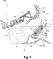
FIG. 8 is a schematic diagram of the cross section of the ventilator of another modification example of the embodiment of the present invention, and is a drawing corresponding to cross section II-II ofFIG. 1 . -
FIG. 9 is a schematic diagram of the cross section of the ventilator according to a comparison example, and is a drawing corresponding to cross section II-II ofFIG. 1 . - Following, a
ventilator 100 according to an embodiment of the present invention is explained while referring to the drawings. - First, the configuration of the
ventilator 100 is explained while referencingFIG. 1 to FIG. 4 . -
FIG. 1 is a front view of theventilator 100.FIG. 2 is a schematic diagram of the cross section when theventilator 100 ofFIG. 1 blows the airflow furthest upward, and is a schematic diagram corresponding to cross section II-II ofFIG. 1 .FIG. 3 is a schematic diagram of cross section III-III ofFIG. 1 .FIG. 4 is a schematic diagram of cross section IV-IV ofFIG. 3 . - In
FIG. 1 , the paper surface vertical direction is the vertical direction of theventilator 100. The paper surface lateral direction is the lateral direction of theventilator 100. The paper surface vertical direction is the airflow direction of theventilator 100. - In
FIG. 2 , the paper surface left side is the upstream side of the airflow direction in theventilator 100. The paper surface right side is the downstream side of the airflow direction in theventilator 100. InFIG. 3 , the paper surface upper side is the upstream side of the airflow direction in theventilator 100. The paper surface lower side is the downstream side of the airflow direction in theventilator 100. - The
ventilator 100 is for vehicles, and for example is provided in the instrument panel, center cluster, etc., of a vehicle compartment. Theventilator 100 guides air for which temperature and humidity have been adjusted by an air conditioning device (not illustrated) inside the vehicle compartment. - As shown in
FIG. 1 to FIG. 3 , theventilator 100 comprises a flow path member 1 (also called a housing or case), abezel part 2, afirst louver unit 3, and asecond louver unit 4. - The
flow path member 1 is an approximately cylindrically shaped member. As shown inFIG. 3 , aninflow port 12 and anoutflow port 13 open at both ends of theflow path member 1. - As shown in
FIG. 2 andFIG. 3 , a flow path 11 (space through which air flows) through which airflow can pass is formed inside theflow path member 1. A duct (not illustrated) is connected to theinflow port 12. The airflow sent from the air conditioning device via the duct to theflow path 11 flows in from theinflow port 12. The airflow that flowed into theflow path 11 flows inside theflow path 11, and flows out from theoutflow port 13 to thebezel part 2. Rather than the flow for which the direction can be changed by thefirst louver unit 3 and thesecond louver unit 4, the direction of the airflow that flows from upstream to downstream as a whole in theflow path 11 interior is called the "airflow direction." Said another way, the "airflow direction" is the extension direction of theflow path 11, or is the direction parallel to aninner wall 11a of theflow path 11. Details of the airflow are described later. - As shown in
FIG. 2 andFIG. 3 , thebezel part 2 is a part provided at theoutflow port 13 side, and is a part that forms anopening part 110 that blows air in theventilator 100. Thebezel part 2 comprises a firstinclined member 21, a pair ofside walls interior panel 24. - As shown in
FIG. 1 , the firstinclined member 21 is a member that forms a portion of the opening part 110 (partitions a portion of the contour of the opening part 110). The firstinclined member 21 is arranged at a position at the lower side in theopening part 110. As shown inFIG. 2 , the firstinclined member 21 is a member of a shape that is inclined so that the opening area of theopening part 110 widens toward the downstream side from the upstream side of the airflow direction inside theventilator 100 with the surface starting from avertex 21a. An inclination angle R1 which is the angle between the tangent near thevertex 21a of the firstinclined member 21 and the airflow direction (also called the direction when the air flows straight toward theopening part 110 from theinflow port 12; inFIG. 2 , shown by a dashed line near thevertex 21a) is within a range in which the Coanda effect, in which the airflow clings to the surface of the firstinclined member 21, occurs easily (0 degrees < R1 < 40 degrees). The Coanda effect occurs particularly easily when the inclination angle R1 is in the range of 0 degrees < R1 < 30. The Coanda effect occurs markedly most easily when the inclination angle R1 is 24 degrees. - As shown in
FIG. 1 andFIG. 2 , the firstinclined member 21 forms the bottom part in theopening part 110. Normally, theventilator 100 is arranged below the position of the eye of an occupant inside the vehicle compartment. For that reason, when the occupant views theventilator 100, the bottom part of theopening part 110 is easy to see. The firstinclined member 21 of the present embodiment is a decorative plate (finisher) that the occupant sees inside the vehicle compartment. On the surface of the first inclined member 21 (surface exposed inside the vehicle compartment), it is possible to have plating, painting, film decoration, matte treatment, decoration, etc., implemented, and also possible to be decorated with synthetic leather, genuine leather, wood grain film, etc. As shown inFIG. 2 , by having the firstinclined member 21 that also functions as a decorative plate penetrate to the back of the opening part 110 (in the range at which the firstinclined member 21 at least faces a vertical louver 31) with a gentle incline, a design with a sense of depth in which the decorative plate penetrates the interior of theventilator 100 is achieved. As a result, it is possible to give the occupant an impression of a highquality sense. As shown inFIG. 1 , with the present embodiment, the firstinclined member 21 extends in the width direction beyond the opening part 110 (lateral direction inFIG. 1 ). - As shown in
FIG. 1 , the pair ofside walls opening part 110. Specifically, the pair ofside walls opening part 110. As shown inFIG. 3 , bearingparts vertical louver 31 described later are provided on the pair ofside walls - The pair of
side walls vertical louver 31 such as is disclosed in the specification ofEuropean Patent Application Publication No. 0289065 (EP0289065A1 ). Specifically, at the position of the pair ofside walls FIG. 1 , it is also possible to have a structure in which instead of the pair ofside walls vertical louver 31 shown in FIG. 31) and projects facing the paper front side from the paper back side ofFIG. 1 , so that the louver imitating side wall supports thevertical louver 31. With such a structure, when thevertical louver 31 is positioned in a reference state described later, thevertical louver 31 and the louver imitation side wall are aligned in a straight line, and it appears that there is a wider louver than the actualvertical louver 31. - As shown in
FIG. 1 , theinterior panel 24 is a member arranged at a position above the firstinclined member 21, and that faces the firstinclined member 21. As shown inFIG. 2 , theinterior panel 24 is a member that is shaped at an inclination angle that is different from the inclination angle R1 of the firstinclined member 21, and that is inclined so that the opening area of theopening part 110 widens facing the downstream side from the upstream side of the airflow direction. An inclination angle R2 which is the angle between the vicinity of the starting point of the inclination at the upstream side of the airflow direction in theinterior panel 24 and the airflow direction (line shown by a dashed line inFIG. 2 ) is 40 degrees or greater. - The
interior panel 24 forms theopening part 110 together with the firstinclined member 21 and the pair ofside walls opening part 110 is formed by the firstinclined member 21, the pair ofside walls interior panel 24. - The
interior panel 24 is a decorative plate (finisher) seen by the occupant inside the vehicle compartment, and has the same or different decoration implemented to that of the firstinclined member 21. - As shown in
FIG. 1 to FIG. 3 , thefirst louver unit 3 has thevertical louver 31 as the first louver, aknob 32, and afork member 33. - The
vertical louver 31 is an approximately plate-shaped member. As shown inFIG. 3 , thevertical louver 31 has a width L1 formed to be approximately the same as the width of theopening part 110. Also, in thevertical louver 31, a length L2 (airflow direction length) is formed to be a level at which when thevertical louver 31 is rotating, it does not interfere with theinner wall 11a of theflow path 11, the inner wall of theoutflow port 13, or the inner wall of theopening part 110, etc. - The
vertical louver 31 is arranged inside theopening part 110 by being supported by the pair ofside walls Shaft parts 3 1a, 3 1b of thevertical louver 31 are rotation shafts, and are supported by theside walls vertical louver 31 can rotate in the vertical direction of theventilator 100 centered on the rotation center O shown inFIG. 2 . - As shown in
FIG. 2 andFIG. 4 , theknob 32 is a member mounted on thevertical louver 31. Theknob 32 is mounted to be able to slide in the lateral direction (width L1 direction of thevertical louver 31 shown inFIG. 3 ) of theventilator 100. When thevertical louver 31 rotates in the vertical direction of theventilator 100 centered on theshaft parts knob 32 rotates in the vertical direction of theventilator 100 together with the vertical louver 31 (seeFIG. 2 ). As shown inFIG. 2 , theshaft part 32a of theknob 32 is the end part at the upstream side in the airflow direction of theknob 32. Also, theend part 32b is the end part closest to the firstinclined member 21 in the maximum angle state (details are described later) shown inFIG. 2 . As shown inFIG. 2 , theknob 32 is mounted to be able to slide on the lower surface (surface facing the first inclined member 21) of thevertical louver 31, so theknob 32 exists partially between thevertical louver 31 and the firstinclined member 21. Theknob 32 may also be mounted on thevertical louver 31 to wrap around the outer periphery of thevertical louver 31 in the cross section ofFIG. 2 . - As shown in
FIG. 2 , by a user moving theknob 32 in the vertical direction, thevertical louver 31 and theknob 32 rotate centered on the rotation axis. The vertical louver 31changes up and down of the airflow direction flowing from the air conditioning device according to the arrangement within the maximum rotation range which is the range in which rotation is possible. - In the maximum rotation range, the angle of the
vertical louver 31 when theventilator 100 blows the airflow furthest upward is called the "maximum angle," and the state of thevertical louver 31 at that time is called the "maximum angle state" (seeFIG. 2 ). The maximum angle state is the angle at which anupstream end part 31c at the upstream side in the airflow direction of thevertical louver 31 is closest to the firstinclined member 21. Also, the end part closest to the firstinclined member 21 in thevertical louver 31 in the maximum angle state is called aproximal end part 31d. InFIG. 2 , theupstream end part 31c and theproximal end part 31d are at different locations, but they may also be at the same location. Specifically, in the maximum angle state, theupstream end part 31c may be at the location closest to the firstinclined member 21 of thevertical louver 31. - On the other hand, in the maximum rotation range, the angle of the
vertical louver 31 when theventilator 100 blows the airflow furthest downward is called the "reverse maximum angle," and the state of thevertical louver 31 at that time is called the "reverse maximum angle state" (seeFIG. 6 described later). - Also, in the maximum angle range, the angle of the
vertical louver 31 that is parallel to theinner wall 1 1a of the flow path 11 (angle of thevertical louver 31 shown by the double dot-dash line inFIG. 2 ) is called the "reference angle." The reference angle is the angle when theventilator 100 blows air toward the neck of the occupant when an occupant of a prescribed height (e.g., 175 cm) is seated. The state when thevertical louver 31 is at the reference angle is called the "reference state." InFIG. 2 , the reference angle is shown by the single-dash line N. InFIG. 2 , it looks like there is an angle between the line N and theinner wall 1 1a of theflow path 11, but in the reference state, both items are actually parallel. - As shown in
FIG. 3 , thefork member 33 is linked to the end part at the upstream side of the airflow direction of theknob 32. As shown inFIG. 4 , theknob 32 and thefork member 33 are connected via apin 34. As shown inFIG. 3 , apin member 48 of thesecond louver unit 4 described later is fitted betweenprojections fork member 33. - As shown in
FIG. 1 andFIG. 3 , thesecond louver unit 4 haslateral louvers 41 to 46 as a plurality of second louvers, alink member 47, and thepin member 48. As shown inFIG. 3 , thesecond louver unit 4 is arranged further to the upstream side in the airflow direction than thefirst louver unit 3 inside theflow path 11. - As shown in
FIG. 1 , the plurality oflateral louvers 41 to 46 are linked with thelink member 47 interposed. Thelateral louvers 41 to 46 are provided in the direction intersecting thevertical louver 31, and are arranged further to the upstream side in the airflow direction than thevertical louver 31. Also, thelateral louvers 41 to 46 rotate in the lateral direction inFIG. 1 centered on a prescribed shaft part (inFIG. 2 ,lateral louver 44 and ashaft part 44a of thelateral louver 44 are shown). Of the plurality oflateral louvers 41 to 46, thelateral louver 44 closest to the space between theprojections fork member 33 has thepin member 48 provided for connecting thesecond louver unit 4 and the fork member 33 (seeFIG. 1 to FIG. 4 ). - When the
knob 32 and thefork member 33 slide in the lateral direction of the ventilator 100 (width L1 direction of thevertical louver 31 shown inFIG. 3 ), thepin member 48 rotates in the lateral direction of theventilator 100 together with that. When thepin member 48 rotates, in conjunction with that, thelateral louvers 41 to 46 tilt toward the rotation direction of the pin member 48 (specifically, the lateral direction of the ventilator 100). Thelateral louvers 41 to 46 change the lateral flow direction of the airflow that flows from the air conditioning device according to the inclination state. - As shown in
FIG. 2 , an auxiliaryvertical louver 5 is provided in theflow path 11 inside theflow path member 1. The auxiliaryvertical louver 5 is linked to thevertical louver 31 via a connecting member 51 (seeFIG. 1 ). The auxiliaryvertical louver 5 rotates in the same direction as thevertical louver 31 and theknob 32 in accordance with rotation of thevertical louver 31 and theknob 32 in the vertical direction of theventilator 100. The auxiliaryvertical louver 5 changes the vertical flow direction of the air flowing from the air conditioning device. - As shown in
FIG. 2 , aconvex member 6 and aguide member 7 are arranged inside theflow path 11 of theflow path member 1. - Here, before explaining the
convex member 6 and theguide member 7, details of the arrangement of thevertex 21a of the firstinclined member 21 which is an element that determines the arrangement of theconvex member 6 and theguide member 7 is explained. - As shown in
FIG. 2 , thevertex 21a is at the location at which the opening area of theopening part 110 is narrowest in the firstinclined member 21. Also, thevertex 21a is the end part at the upstream side in the airflow direction. Specifically, thevertex 21a is the part closest to theoutflow port 13 of theflow path member 1 of the firstinclined member 21. - As shown in
FIG. 2 , thevertex 21a is arranged further to the upstream side in the airflow direction than theupstream end part 31c of thevertical louver 31 in the maximum angle state. - Next, the
convex member 6 and theguide member 7 are explained. - As shown in
FIG. 2 , theconvex member 6 is arranged at a position adjacent to thevertex 21a of the firstinclined member 21 at the upstream side in the airflow direction. Theconvex member 6 has aconvex part 6a and a secondinclined part 6b. - The
convex part 6a is provided extending across all thelateral louvers 41 to 46 seen from the airflow direction. Theconvex part 6a is a part projecting more to the inside of theflow path 11 than thevertex 21a. Here, the inside of theflow path 11 is the side facing the direction separating from the inner circumference surface that forms theflow path 11 of theflow path member 1, specifically, the side facing the position of thefirst louver unit 3 in the reference state shown by the two-dot-dash line inFIG. 2 from theinner wall 11a of the lower side of the flow path member. Theconvex part 6a can be said to be projecting toward the inside of theflow path 11 in the direction orthogonal to both the rotation axis direction of thevertical louver 31 and the airflow direction (specifically, approximately the vertical direction inFIG. 2 ). Theconvex part 6a may also be provided extending across a portion of thelateral louvers 41 to 46 (plurality of lateral louvers among thelateral louvers 41 to 46) seen from the airflow direction. - The
convex part 6a, in further detail, projects upward from theproximal end part 31d of thevertical louver 31 in the maximum angle state (height is higher) in the direction orthogonal to both the rotation axis direction of thevertical louver 31 and the airflow direction (specifically, approximately the vertical direction inFIG. 2 ). Furthermore, theconvex part 6a is arranged between thevertical louver 31 and thelateral louvers 41 to 46 in the airflow direction. - The
convex 3 mm more than thepart 6a projectsvertex 21a. Preferably, theconvex 3 mm or more from thepart 6a projectsvertex 21a in the direction noted above in a range in which thefirst louver unit 3 does not reach the rotation orbit from the reference state to the maximum angle state (arc-shaped double-dot-dash line that connects the position of theend part 32a shown by the solid line inFIG. 2 and theend part 32a shown by the double-dot-dash line inFIG. 2 ). - As shown in
FIG. 2 , the secondinclined part 6b is an inclined plane that is positioned further to the upstream side in the airflow direction than theconvex part 6a, and that is inclined to face the inside of theflow path 11 facing the downstream side from the upstream side of the airflow direction. - As shown in
FIG. 2 , theguide member 7 is arranged further to the upstream side in the airflow direction than theconvex member 6. Also, theguide member 7 has a secondconvex part 7a. The secondconvex part 7a projects more toward the inside of theflow path 11 than theproximal end part 31d in the direction orthogonal to both the rotation axis direction of thevertical louver 31 and the airflow direction (specifically, approximately the vertical direction with respect toFIG. 2 ). In the present embodiment, the secondconvex part 7a projects facing more to the inside of theflow path 11 than theconvex part 6a. In the present embodiment, the secondconvex part 7a is provided extending across all of thelateral louvers 41 to 46 seen from the airflow direction, but it is also possible to be provided extending across a portion of thelateral louvers 41 to 46) (a plurality of lateral louvers of thelateral louvers 41 to 46) seen from the airflow direction. - The
guide member 7 forms aguide flow path 8 together with theconvex member 6. Theguide flow path 8 is formed so that the flow path cross section area of anoutlet 8b is smaller than the flow path cross section area of aninlet 8a. - Hereafter, referencing
FIG. 5 ,FIG. 6 , andFIG. 9 , the action of theventilator 100 when blowing air is explained. -
FIG. 5 is a schematic diagram of the cross section when airflow is blown furthest upward by theventilator 100, and is a drawing correlating to the II-II cross section inFIG. 1 .FIG. 6 is a schematic diagram of the cross section when theventilator 100 is blowing airflow furthest downward, and is a drawing correlating to the II-II cross section inFIG. 1 .FIG. 9 is a schematic diagram of the cross section of aventilator 200 of a comparison example, and is a drawing correlating to the II-II cross section ofFIG. 1 . InFIG. 5 ,FIG. 6 , andFIG. 9 , the flow of air flowing in theventilators - First, referencing
FIG. 5 , a case of the airflow blowing the furthest upward is explained. In this case, thefirst louver unit 3 and the auxiliaryvertical louver 5 are at the maximum angle state, and are inclined to face more upward the more downstream the airflow direction faces. - The airflow sent from the air conditioning device flows into the
flow path 11 from theinflow port 12 of theflow path member 1. The airflow that flows into theflow path 11 can be roughly divided into the airflow that flows to the upper side of theflow path 11 as shown by arrow A (the paper surface upward side inFIG. 2 of theflow path 11, specifically, the side in which the auxiliaryvertical louver 5 is arranged), the airflow that flows to inside theflow path 11 as shown by arrow B (the paper surface center side inFIG. 2 of theflow path 11, specifically, the side nearest the pin member 48), and the airflow that flows to the lower side of theflow path 11 as shown by arrow C and arrow D (the paper surface lower side inFIG. 2 of theflow path 11, the side in which theconvex member 6 and theguide member 7 are arranged). Hereafter, each airflow is explained separately. - The airflow that flows to the upper side of the
flow path 11 flows inside theflow path 11 as shown by arrow A. Specifically, the airflow that flows to the upper side of theflow path 11 first flows facing the extension direction of the flow path 11 (said another way, to the direction parallel to theinner wall 11a of the flow path 11). Thereafter, that airflow has the flow changed to the upward side of theventilator 100 by the auxiliaryvertical louver 5, and is blown facing upward from theoutflow port 13 and theopening part 110. - The airflow that flows to the lower side of the
flow path 11 flow insides theflow path 11 as shown by the arrow C or arrow D. Specifically, the airflow that flows to the lower side of theflow path 11 can be divided into cases of not passing through theguide flow path 8 as shown by arrow C and cases of passing through theguide flow path 8 as shown by arrow D. - A case of not passing through the
guide flow path 8 as shown by arrow C is explained. In that case, the airflow that flows to the lower side of theflow path 11 first flows facing the extension direction of theflow path 11. - After that, that airflow contacts the second
convex part 7a of theguide member 7 and the flow changes to the direction facing thefirst louver 3. The airflow for which the flow has changed merges with the airflow of arrow B and faces theopening part 110. Here, theconvex part 6a is positioned at the downstream side in the airflow direction with respect to the secondconvex part 7a, and theconvex part 6a is adjacent to thevertex 21a of the firstinclined member 21. By doing this, it is possible to suppress the merged airflow noted above from wrapping around to thevertex 21a. As a result, it is possible to prevent the occurrence of the Coanda effect of the air clinging to the surface of the firstinclined member 21. In particular, in the maximum angle state, theconvex part 6a projects more greatly than theproximal end part 31d of thevertical louver 31, so in the maximum angle state, direct flowing of the airflow facing between the firstinclined member 21 and thevertical louver 31 is suppressed. Also, even if a portion of the airflow merged with the airflow of arrow C and arrow B wraps around to bypass theconvex part 6a, first, as noted above, clinging of the airflow near thevertex 21a is suppressed. Furthermore, the firstinclined member 21 is inclined downward facing the downstream side of the airflow direction. Thus, since the firstinclined member 21 is inclined downward facing the downstream side of the airflow direction, a portion of that airflow touching the surface of the firstinclined member 21 is suppressed. - The "adjacent" range between the
convex part 6a and thevertex 21a refers to the distance between thevertex 21a and theconvex part 6a in the range in which the airflow that passes over theconvex part 6a does not wrap around thevertex 21a, and means that the distance from thevertex 21a to theconvex part 6a is approximately 3 mm or less. Provided the distance from thevertex 21a to the secondconvex part 7a is 3 mm or less, the secondconvex part 7a and thevertex 21a can be understood as being adjacent. - Here, because the
first louver unit 3 and the auxiliaryvertical louver 5 are inclined facing upward, the airflow facing thefirst louver unit 3 is guided to flow upward by thefirst louver unit 3, and is blown from theoutflow port 13 and theopening part 110 facing upward. - A case of passing through the
guide flow path 8 as shown by arrow D is explained. In that case, the air flowing to the lower side of theflow path 11 first flows facing the extension direction of theflow path 11. - Thereafter, as shown by arrow D, that air flows toward the
outlet 8b from theinlet 8a of theguide flow path 8. The air flowing in theguide flow path 8 has the flow changed to face upward by the secondinclined part 6b. Also, as explained above, theguide flow path 8 is formed so that the flow path cross section area of theoutlet 8b is smaller than the flow path cross section area of theinlet 8a. Specifically, theguide flow path 8 is formed so that theoutlet 8b is narrower than theinlet 8a. For that reason, theguide flow path 8 is able to speed up the flow speed of the air flowing in theguide flow path 8 at the outlet side, causing the airflow to flow out vigorously from theoutlet 8b. - The airflow for which the flow speed became faster and the flow changed to upward by passing through the
guide flow path 8 merges with the airflow of arrow B as shown by arrow D, and flows toward thevertical louver 31 of thefirst louver unit 3. The airflow blown from theoutlet 8b has a faster flow speed as noted above, so exhibits an effect of pushing the airflow of arrow B to face the upper side. By working in this way, by the airflow of arrow D merging with the airflow of arrow B, the airflow wrapping around to thevertex 21a is suppressed. As a result, it is possible to more effectively prevent the occurrence of the Coanda effect of air clinging to the surface of the firstinclined member 21. - The air flowing to inside the
flow path 11 flows inside theflow path 11 as shown by arrow B. Specifically, the airflow that flows to inside theflow path 11 first flows facing the extension direction of theflow path 11. After that, that airflow merges with the air flowing facing upward from the lower surface inside the flow path 11 (airflow of the flow of arrow C and arrow D), and the flow changes to the upward side of theventilator 100. Also, by the airflow contacting thevertical louver 31, the airflow direction changes, flowing facing the upward side along thevertical louver 31, and is blown from theoutflow port 13 and theopening part 110. - In this way, even if the airflow that flowed into the
flow path 11 of theventilator 100 from the air conditioning device passes through any of the upper side, the inside, or the lower side in theflow path 11, it is blown well upward from theopening part 110. Said another way, when desiring to blow the airflow upward, having the air flow downward opposite to the intended direction is suppressed. - Here, referring to
FIG. 9 , theventilator 200 is explained as a comparison example which is the same as theventilator 100 shown inFIG. 1 to FIG. 4 other than not comprising theconvex member 6 and theguide member 7. - As shown in
FIG. 9 , with theventilator 200, the airflow that flows to the lower side of theflow path 11 from the air conditioning device passes through the space between thevertex 21a of the firstinclined member 21 and the vertical louver 31 (proximal end part 31d) without the flow changing as shown by arrow J. As explained above, in terms of the structure of the firstinclined member 21, the inclination angle R1 which is the angle between the vicinity of thevertex 21a of the firstinclined member 21 and the airflow direction (line shown by a dashed line inFIG. 2 ) is 40 degrees or less. - When this inclination angle R1 is less than 40 degrees (particularly in the range of 0 degrees < R1 < 30 degrees), when the air flows as shown by arrow J of
FIG. 9 of the comparison example, when that airflow contacts thevertex 21a, it flows to the downward side along the firstinclined member 21 as shown by arrow K due to the Coanda effect. Specifically, when there is noconvex member 6 or guidemember 7, there are cases of the air flowing in the opposite direction to what was intended, as with the air flowing downward despite thevertical louver 31 facing upward. - To prevent the flow of air in this way, it is conceivable to have the
vertical louver 31 drawn to the upstream side of the airflow direction, and when in the maximum angle state, the space between thevertical louver 31 and the firstinclined member 21 will close. - However, in the
ventilator 200 of a structure in which thevertical louver 31 is arranged in the vicinity of theopening part 110, even when thevertical louver 31 is drawn to the rear, before thevertical louver 31 abuts the firstinclined member 21, theknob 32 abouts the firstinclined member 21. As a result, a gap occurs in the part in which theknob 32 is not interposed between thevertical louver 31 and the firstinclined member 21, and the Coanda effect occurs at this part. - In contrast to this, in the
ventilator 100 comprising theconvex member 6 and theguide member 7, as shown inFIG. 5 , when thevertical louver 31 is rotated to the maximum angle, the airflow trying to go to the space between thevertex 21a at the upstream side in the airflow direction of the firstinclined member 21 and theproximal end part 31d of the vertical louver 31 (the airflow shown by arrow C inFIG. 5 , particularly the airflow facing thevertex 21a of the first inclined member 21) contacts the secondconvex part 7a before flowing through that space and has the flow changed. Also, because theconvex part 6a is adjacent to thevertex 21a, theconvex part 6a obstructs the airflow going toward thevertex 21a. For that reason, the airflow wrapping around to that space is suppressed. Therefore, it is possible to prevent the Coanda effect from occurring at the firstinclined member 21 and having the airflow pass through that space and flow opposite to the intended direction (flowing as shown by arrow J and arrow K inFIG. 9 ). - Also, by providing the
guide flow path 8 using the secondinclined part 6b and theguide member 7, as shown by arrow D inFIG. 5 , the air flowing to the lower side of theflow path 11 is guided upward. The air flows facing upward as shown by arrow D inFIG. 5 , so by doing this as well, flowing of the airflow to the space between thevertex 21a of the firstinclined member 21 and theproximal end part 31d of thevertical louver 31 is suppressed. In particular, it is possible to suppress flowing of the airflow trying to contact thevertex 21a of the firstinclined member 21, and to suppress the occurrence of the Coanda effect of the airflow clinging from thevertex 21a. - Furthermore, in the
guide flow path 8, the flow path cross section area of theoutlet 8b is formed to be smaller than the flow path cross section area of theinlet 8a. Specifically, theoutlet 8b of theguide flow path 8 is narrower than theinlet 8a. For that reason, the airflow that passes through theguide flow path 8 has the flow speed made faster, and goes upward vigorously. By doing this as well, it is possible to suppress the occurrence of the Coanda effect of the airflow clinging to the firstinclined member 21. - Next, referring to
FIG. 6 , a case of the airflow being blown furthest downward is explained. In this case, thefirst louver unit 3 and the auxiliaryvertical louver 5 are in the reverse maximum angle state, and are inclined to face downward the further downstream in the airflow direction they are. Specifically, thefirst louver unit 3 can rotate within a range from the position shown inFIG. 5 to the position shown inFIG. 6 (maximum rotation range). - The
ventilator 100 blows air sent from the air conditioning device to theflow path 11 from theinflow port 12 of theflow path member 1. The airflow that flows into theflow path 11 can be roughly divided into the airflow that flows to the upper side of theflow path 11 as shown by arrow E, the airflow that flows to inside theflow path 11 as shown by arrow F, and the airflow that flows to the lower side of theflow path 11 as shown by arrow G and arrow H. Hereafter, each airflow is explained separately. - The air that flows to the upper side of the
flow path 11 flows inside theflow path 11 as shown by arrow E. Specifically, the airflow that flows in from the upper side of theflow path 11 first flows facing the extension direction of theflow path 11. After that, that air has the flow changed to the downward side of theventilator 100 by the auxiliaryvertical louver 5, and is blown from theoutflow port 13 and theopening part 110 facing the downward side. - However, in the airflow that flows at the upper side of the
flow path 11, it is possible that the airflow will flow without contacting the auxiliaryvertical louver 5, with the flow left unchanged, in the space between theinterior panel 24 and thefirst louver unit 3. However, even if there is airflow such as that described above, by having the inclination angle R2 of theinterior panel 24 be 40 degrees or greater (e.g., 42 degrees), the phenomenon of that air flowing facing upward due to the Coanda effect is suppressed. Specifically, in the reverse maximum angle state, even if the airflow is blown straight from theventilator 100, having the airflow blown to the upper surface (the opposite direction to the intended direction) is suppressed. - The airflow that flows to inside the
flow path 11 flows in theflow path 11 as shown by arrow F. Specifically, the airflow that flows in from inside theflow path 11 first flows facing the extension direction of theflow path 11. Thereafter, that airflow flows facing the downward side along thevertical louver 31 and theknob 32 by contacting thevertical louver 31 and theknob 32 that are inclined facing downward, and is blown from theoutflow port 13 and theopening part 110 facing the downward side as shown by arrow I. - The airflow that flows to the lower side of the
flow path 11 flows in theflow path 11 as shown by arrow G or arrow H. Specifically, the airflow that flows in from the lower side of theflow path 11 can be divided into a case when it does not flow through theguide flow path 8 as shown by arrow G, and a case when it passes through theguide flow path 8 as shown by arrow H. - The airflow that flows in from the lower side of the
flow path 11 as shown by arrow G and arrow H, though it flows facing upward once by theconvex part 6a and the secondconvex part 7a or by theguide flow path 8, it merges with the airflow of arrow F, and soon contacts thefirst louver unit 3 that is inclined downward. That airflow is guided to flow downward along thefirst louver unit 3, and is blown from theoutflow port 13 and theopening part 110 facing the downward side as shown by arrow I. - In this way, the airflow that flowed into the
flow path 11 of theventilator 100 from the air conditioning device is not blown upward from theopening part 110 even if it passes through any of the upper side, the inside, or the lower side in theflow path 11. Specifically, the airflow does not flow in the opposite direction to the intended direction. - According to the embodiment above, the effects shown hereafter are exhibited.
- The
ventilator 100 that blows air through theflow path 11 and from theopening part 110 comprises: thevertical louver 31 on which theknob 32 is mounted; the pair ofside walls vertical louver 31 to be able to rotate, and that form a portion of theopening part 110; and the firstinclined member 21 that forms another portion of theopening part 110 between the pair ofside walls opening part 110 widens facing the downstream side from the upstream side of the airflow direction. The firstinclined member 21 has thevertex 21a of inclination that is positioned at the upstream side in the airflow direction. In the maximum angle state in which theupstream end part 31c of the upstream side in the airflow direction of thevertical louver 31 has thevertical louver 31 rotated to be closest to the firstinclined member 21, theupstream end part 31c of thevertical louver 31 is positioned further to the downstream side in the airflow direction than thevertex 21a. Theventilator 100 further comprises theconvex part 6a arranged adjacent at the upstream side in the airflow direction to thevertex 21a, and theconvex part 6a projects further to the inside of theflow path 11 than thevertex 21a in the direction orthogonal to both the rotation axis of thevertical louver 31 and the airflow direction. - As a result, when the
vertical louver 31 is rotated to the maximum angle state, having the airflow contact thevertex 21a of the firstinclined member 21 is suppressed by theconvex part 6a, so it is possible to prevent the occurrence of the Coanda effect with thevertex 21a. By doing this, it is possible to suppress flowing of the airflow in the direction opposite to the intended direction. - Also, in a preferred mode, in the maximum angle state, the
convex part 6a projects further to the inside of theflow path 11 than the position of theproximal end part 31d of thevertical louver 31 closest to the firstinclined member 21. - As a result, when the
vertical louver 31 is rotated to the maximum angle state, flowing of the airflow to the space between thevertex 21a of the firstinclined member 21 and theproximal end part 31d of thevertical louver 31 is suppressed by theconvex part 6a. Therefore, the occurrence of the Coanda effect with the firstinclined member 21 is suppressed, and it is possible to effectively prevent the airflow from passing through that space and flowing opposite to the intended direction. - Also, the
ventilator 100 further comprises the secondinclined part 6b that is adjacent to theconvex part 6a at the upstream side in the airflow direction, and that is inclined facing the inside of theflow path 11 in the direction facing the downstream side from the upstream side of the airflow direction. - As a result, the airflow that flows at the lower side of the
flow path 11 is guided to face upward. For that reason, in the maximum angle state, flowing of the airflow in the space between thevertex 21a of the firstinclined member 21 and theproximal end part 31d of thevertical louver 31 is suppressed by that airflow. Therefore, the occurrence of the Coanda effect with the firstinclined member 21 is suppressed, and it is possible to prevent the airflow from passing through that space and flowing opposite to the intended direction (flowing as shown by arrow J and arrow K ofFIG. 9 ). - Also, the
ventilator 100 further comprises theguide member 7 that forms theguide flow path 8 together with the secondinclined part 6b, and theguide member 7 has the secondconvex part 7a that projects further to the inside of theflow path 11 than thevertex 21a. In more detail, the secondconvex part 7a projects further to the inside of theflow path 11 than theproximal end part 31d. - As a result, in the maximum angle state, the flowing of the airflow to the space between the
vertex 21a at the upstream side in the airflow direction of the firstinclined member 21 and theproximal end part 31d of thevertical louver 31 is also suppressed by the secondconvex part 7a. Therefore, it is possible to prevent the airflow from passing through that space and flowing opposite to the intended direction. - The second
convex part 7a projects more greatly to inside theflow path 11 than theconvex part 6a. However, the secondconvex part 7a has a reduced effect on appearance because it is positioned in the back side of theflow path 11 when theflow path 11 is seen from the direction of theopening part 110. Specifically, by making theconvex part 6a that is easy for the occupant to see smaller, and making the secondconvex part 7a that is relatively difficult to see by the occupants larger, suppression of the occurrence of the Coanda effect is achieved while reducing the effect on the appearance. - Also, as shown in
FIG. 1 , when theflow path 11 is seen from the direction of theopening part 110, theconvex part 6a and the secondconvex part 7a appear to be in step form. If theconvex part 6a is approximately the same height as the secondconvex part 7a, when theflow path 11 is seen from theopening part 110, in contrast to the wall surface of theconvex part 6a (surface that can be seen inFIG. 1 ) being visibly conspicuous, being in the kind of step form shown inFIG. 1 is a contrivance that makes it visually inconspicuous. - Also, the
outlet 8b of theguide flow path 8 is narrower than theinlet 8a of theguide flow path 8. - As a result, the airflow that flows inside the
guide flow path 8 is flowed out vigorously upward from theoutlet 8b. By doing this as well, in the maximum angle state, flowing of the airflow in the space between thevertex 21a of the upstream side in the airflow direction of the firstinclined member 21 and theproximal end part 31d of thevertical louver 31 is suppressed. - Above, embodiments of the present invention were explained, but the embodiments merely show a portion of the application examples of the present invention, and are not intended to limit the technical scope of the present invention to specific configurations of the above embodiments.
- In the embodiments above, a case was explained in which the first
inclined member 21 is arranged below theopening part 110, and in the maximum angle state, thefirst louver unit 3 is inclined upward. However, it is also possible to apply the abovementioned configuration in a case when the firstinclined member 21 is arranged above theopening part 110, and in the maximum angle state, thefirst louver unit 3 is inclined downward. Also, in a case when thelateral louvers 41 to 46 are arranged further to the inside of the vehicle compartment than the vertical louver 31 (this can be understood as a case when a configuration such as inFIG. 1 is inclined by 90 degrees and arranged inside the vehicle compartment), it is possible to apply the abovementioned configuration with the abovementionedvertical louver 31 being replaced by the louver closest to the firstinclined member 21 among thelateral louvers 41 to 46. - Also, as shown by the modification example shown in
FIG. 7 , it is also possible to have a configuration in which aguide member 17 does not comprise the secondconvex part 7a. In that configuration as well, if there is theconvex part 6a, wrapping around of the airflow to thevertex 21a of the upstream side in the airflow direction of the firstinclined member 21 is suppressed. - Also, as shown by another modification example shown in
FIG. 8 , it is also possible to have a configuration that comprises a secondinclined member 16 instead of theconvex member 6 and theguide member 7. - The second
inclined member 16 has aconvex part 16a and aninclined part 16b. Theconvex part 16a and theinclined part 16b are formed integrally. - The
convex part 16a, the same as theconvex part 6a noted above, is adjacent to thevertex 21a of the firstinclined member 21, so it is possible to suppress wrapping around of the airflow to thevertex 21a. As a result, the flowing of air in that space is suppressed. - The
inclined part 16b, the same as the secondinclined part 6b noted above, guides the air flowing to the lower side of theflow path 11 to face upward. As a result, the flowing of air in the space between thevertex 21a of the upstream side in the airflow direction of the firstinclined member 21 and theproximal end part 31d of thevertical louver 31 is suppressed. - According to the
ventilator 100 of this modification example as well, it is possible to prevent the airflow from passing through that space and flowing opposite to the intended direction (flowing as shown by arrow J and arrow K ofFIG. 9 ). - The present application claims priority based on Patent Application No.
2020-118661 filed with the Japanese Patent Office on July 9, 2020
Claims (7)
- A ventilator that blows air through a flow path from an opening part, the ventilator comprising:a first louver on which a knob is mounted;a plurality of second louvers provided in a direction intersecting the first louver, and arranged further to an upstream side in an airflow direction than the first louver;a pair of side walls that support the first louver to be able to rotate, and that form a portion of the opening part; anda first inclined member that forms another portion of the opening part between the pair of side walls, and that is inclined so that an opening area of the opening part widens facing a downstream side from the upstream side in the airflow direction, whereinthe first inclined member has a vertex of inclination that is positioned at the upstream side in the airflow direction,in a maximum angle state in which the first louver is rotated so that an upstream end part of the upstream side in the airflow direction of the first louver is closest to the first inclined member, the upstream end part is positioned further to the downstream side in the airflow direction than the vertex,further comprised is a convex part arranged adjacent at the upstream side in the airflow direction to the vertex, andthe convex part projects further to an inside of the flow path than the vertex in a direction orthogonal to both a rotation axis of the first louver and the airflow direction, and is provided extending across the plurality of second louvers seen from the airflow direction.
- The ventilator according to claim 1, wherein
the convex part is arranged between the first louver and the second louvers in the airflow direction. - The ventilator according to claim 1 or 2, wherein
in the direction orthogonal to both the rotation axis of the first louver and the airflow direction, in the maximum angle state, the convex part projects further inside the flow path than a position of a proximal end part of the first louver closest to the first inclined member. - The ventilator according to any of claims 1 to 3, further comprising
a second inclined part that is adjacent to the convex part at the upstream side in the airflow direction, and that is inclined facing the inside of the flow path in the direction facing the downstream side from the upstream side of the airflow direction. - The ventilator according to claim 4, further comprisinga guide member that, together with the second inclined part, forms a guide flow path that guides the airflow facing the inside of the flow path, whereinthe guide member has a second convex part that projects further to the inside of the flow path than the vertex in the direction orthogonal to both the rotation axis of the first louver and the airflow direction.
- The ventilator according to claim 5, wherein
an outlet of the guide flow path is narrower than an inlet of the guide flow path. - The ventilator according to any of claims 1 to 3, comprisinga second convex part that is positioned further to the upstream side in the airflow direction than the convex part, and that projects further to the inside of the flow path than the vertex in the direction orthogonal to both the rotation axis of the first louver and the airflow direction, whereinthe second convex part projects more greatly than the convex part.
Applications Claiming Priority (2)
| Application Number | Priority Date | Filing Date | Title |
|---|---|---|---|
| JP2020118661A JP6909906B1 (en) | 2020-07-09 | 2020-07-09 | Ventilator |
| PCT/JP2021/025653 WO2022009929A1 (en) | 2020-07-09 | 2021-07-07 | Ventilator |
Publications (3)
| Publication Number | Publication Date |
|---|---|
| EP4180252A1 true EP4180252A1 (en) | 2023-05-17 |
| EP4180252A4 EP4180252A4 (en) | 2024-01-10 |
| EP4180252B1 EP4180252B1 (en) | 2025-04-23 |
Family
ID=76969083
Family Applications (1)
| Application Number | Title | Priority Date | Filing Date |
|---|---|---|---|
| EP21836862.9A Active EP4180252B1 (en) | 2020-07-09 | 2021-07-07 | Ventilator |
Country Status (5)
| Country | Link |
|---|---|
| US (1) | US12291084B2 (en) |
| EP (1) | EP4180252B1 (en) |
| JP (1) | JP6909906B1 (en) |
| CN (1) | CN115362074B (en) |
| WO (1) | WO2022009929A1 (en) |
Families Citing this family (1)
| Publication number | Priority date | Publication date | Assignee | Title |
|---|---|---|---|---|
| JP2023016254A (en) * | 2021-07-21 | 2023-02-02 | 本田技研工業株式会社 | Blowout structure of air conditioner |
Family Cites Families (22)
| Publication number | Priority date | Publication date | Assignee | Title |
|---|---|---|---|---|
| JPS6096111U (en) * | 1983-12-09 | 1985-07-01 | 株式会社ボッシュオートモーティブ システム | Blowout grill for bus cooling equipment |
| IT1203420B (en) | 1987-04-01 | 1989-02-15 | Alfa Lancia Ind | AERATION VENT, ESPECIALLY FOR VEHICLES |
| JP3605577B2 (en) | 2001-05-15 | 2004-12-22 | 本田技研工業株式会社 | Air outlet for air conditioning |
| JP4367110B2 (en) * | 2003-11-28 | 2009-11-18 | 日本プラスト株式会社 | Air outlet structure for vehicles |
| JP4816381B2 (en) * | 2006-09-29 | 2011-11-16 | 豊田合成株式会社 | Air conditioning register |
| JP4890203B2 (en) * | 2006-11-20 | 2012-03-07 | 豊和化成株式会社 | Air blower for vehicle interior |
| JP4971927B2 (en) * | 2007-09-27 | 2012-07-11 | 日本プラスト株式会社 | Wind direction adjustment device |
| JP5597423B2 (en) | 2009-05-29 | 2014-10-01 | 豊田合成株式会社 | Air conditioning register |
| JP5340874B2 (en) * | 2009-10-05 | 2013-11-13 | 豊和化成株式会社 | Air blowing device |
| JP5402871B2 (en) * | 2010-08-06 | 2014-01-29 | ダイキン工業株式会社 | Indoor unit |
| DE102011004988B4 (en) * | 2011-03-02 | 2023-02-09 | Ford Global Technologies, Llc | Air guide nozzle for ventilation of the interior of a motor vehicle |
| JP6008423B2 (en) * | 2011-05-26 | 2016-10-19 | 日本プラスト株式会社 | Wind direction adjustment device |
| KR20160002036A (en) * | 2014-06-30 | 2016-01-07 | 현대모비스 주식회사 | Air vent for Vehicle |
| JP2016088188A (en) * | 2014-10-31 | 2016-05-23 | 豊和化成株式会社 | Air blowout device |
| US10189334B2 (en) * | 2014-12-11 | 2019-01-29 | Toyota Jidosha Kabushiki Kaisha | Register |
| JP6260543B2 (en) * | 2015-01-13 | 2018-01-17 | トヨタ自動車株式会社 | register |
| JP6500235B2 (en) * | 2015-11-16 | 2019-04-17 | 豊田合成株式会社 | Air conditioning register |
| JP6863755B2 (en) | 2016-05-26 | 2021-04-21 | 豊和化成株式会社 | register |
| JP2018203088A (en) * | 2017-06-06 | 2018-12-27 | 豊和化成株式会社 | register |
| JP7013149B2 (en) * | 2017-06-30 | 2022-01-31 | 豊和化成株式会社 | register |
| JP7105106B2 (en) | 2018-05-25 | 2022-07-22 | 日本プラスト株式会社 | wind direction adjuster |
| JP6895662B2 (en) | 2019-01-24 | 2021-06-30 | 住友ゴム工業株式会社 | Fractionation method and capture method of specific cells |
-
2020
- 2020-07-09 JP JP2020118661A patent/JP6909906B1/en active Active
-
2021
- 2021-07-07 EP EP21836862.9A patent/EP4180252B1/en active Active
- 2021-07-07 US US17/924,732 patent/US12291084B2/en active Active
- 2021-07-07 CN CN202180025302.2A patent/CN115362074B/en active Active
- 2021-07-07 WO PCT/JP2021/025653 patent/WO2022009929A1/en not_active Ceased
Also Published As
| Publication number | Publication date |
|---|---|
| JP6909906B1 (en) | 2021-07-28 |
| WO2022009929A1 (en) | 2022-01-13 |
| JP2022015659A (en) | 2022-01-21 |
| US20230182544A1 (en) | 2023-06-15 |
| CN115362074A (en) | 2022-11-18 |
| CN115362074B (en) | 2025-01-24 |
| US12291084B2 (en) | 2025-05-06 |
| EP4180252A4 (en) | 2024-01-10 |
| EP4180252B1 (en) | 2025-04-23 |
Similar Documents
| Publication | Publication Date | Title |
|---|---|---|
| JP6610784B2 (en) | Air blowing device | |
| US9724981B2 (en) | Air conditioning register | |
| JP4816381B2 (en) | Air conditioning register | |
| JP7013149B2 (en) | register | |
| JP5210119B2 (en) | register | |
| JP5827099B2 (en) | register | |
| US10675947B2 (en) | Air blower device | |
| JP2008543664A (en) | Air blowing nozzle | |
| JP2005306224A (en) | Air conditioning resistor | |
| JP2013116650A (en) | Register | |
| JP2008149828A (en) | Thin register for air-conditioning | |
| EP4180252B1 (en) | Ventilator | |
| JP4971927B2 (en) | Wind direction adjustment device | |
| JP2017213955A (en) | Thin type register | |
| JPH07117066B2 (en) | Cross flow fan device | |
| JP2018203088A (en) | register | |
| JP6817177B2 (en) | Air conditioning register | |
| JP4150541B2 (en) | Air blowout adjustment register | |
| EP4047213B1 (en) | Blower | |
| JP4069700B2 (en) | Wind direction adjustment device | |
| JP7231460B2 (en) | air blower | |
| JP7835153B2 (en) | Register | |
| JP4007066B2 (en) | Bent grill structure | |
| JP6071563B2 (en) | register | |
| JP7086493B2 (en) | Vehicle air conditioner |
Legal Events
| Date | Code | Title | Description |
|---|---|---|---|
| STAA | Information on the status of an ep patent application or granted ep patent |
Free format text: STATUS: THE INTERNATIONAL PUBLICATION HAS BEEN MADE |
|
| PUAI | Public reference made under article 153(3) epc to a published international application that has entered the european phase |
Free format text: ORIGINAL CODE: 0009012 |
|
| STAA | Information on the status of an ep patent application or granted ep patent |
Free format text: STATUS: REQUEST FOR EXAMINATION WAS MADE |
|
| 17P | Request for examination filed |
Effective date: 20221125 |
|
| AK | Designated contracting states |
Kind code of ref document: A1 Designated state(s): AL AT BE BG CH CY CZ DE DK EE ES FI FR GB GR HR HU IE IS IT LI LT LU LV MC MK MT NL NO PL PT RO RS SE SI SK SM TR |
|
| DAV | Request for validation of the european patent (deleted) | ||
| DAX | Request for extension of the european patent (deleted) | ||
| A4 | Supplementary search report drawn up and despatched |
Effective date: 20231213 |
|
| RIC1 | Information provided on ipc code assigned before grant |
Ipc: F24F 13/14 20060101ALI20231207BHEP Ipc: F24F 13/08 20060101ALI20231207BHEP Ipc: B60H 1/34 20060101AFI20231207BHEP |
|
| GRAP | Despatch of communication of intention to grant a patent |
Free format text: ORIGINAL CODE: EPIDOSNIGR1 |
|
| STAA | Information on the status of an ep patent application or granted ep patent |
Free format text: STATUS: GRANT OF PATENT IS INTENDED |
|
| INTG | Intention to grant announced |
Effective date: 20241119 |
|
| RIC1 | Information provided on ipc code assigned before grant |
Ipc: F24F 13/14 20060101ALI20241108BHEP Ipc: B60H 1/34 20060101AFI20241108BHEP |
|
| GRAS | Grant fee paid |
Free format text: ORIGINAL CODE: EPIDOSNIGR3 |
|
| GRAA | (expected) grant |
Free format text: ORIGINAL CODE: 0009210 |
|
| STAA | Information on the status of an ep patent application or granted ep patent |
Free format text: STATUS: THE PATENT HAS BEEN GRANTED |
|
| AK | Designated contracting states |
Kind code of ref document: B1 Designated state(s): AL AT BE BG CH CY CZ DE DK EE ES FI FR GB GR HR HU IE IS IT LI LT LU LV MC MK MT NL NO PL PT RO RS SE SI SK SM TR |
|
| REG | Reference to a national code |
Ref country code: GB Ref legal event code: FG4D |
|
| REG | Reference to a national code |
Ref country code: CH Ref legal event code: EP |
|
| REG | Reference to a national code |
Ref country code: DE Ref legal event code: R096 Ref document number: 602021029752 Country of ref document: DE |
|
| REG | Reference to a national code |
Ref country code: IE Ref legal event code: FG4D |
|
| PGFP | Annual fee paid to national office [announced via postgrant information from national office to epo] |
Ref country code: FR Payment date: 20250630 Year of fee payment: 5 |
|
| REG | Reference to a national code |
Ref country code: NL Ref legal event code: MP Effective date: 20250423 |
|
| PG25 | Lapsed in a contracting state [announced via postgrant information from national office to epo] |
Ref country code: NL Free format text: LAPSE BECAUSE OF FAILURE TO SUBMIT A TRANSLATION OF THE DESCRIPTION OR TO PAY THE FEE WITHIN THE PRESCRIBED TIME-LIMIT Effective date: 20250423 |
|
| REG | Reference to a national code |
Ref country code: AT Ref legal event code: MK05 Ref document number: 1787464 Country of ref document: AT Kind code of ref document: T Effective date: 20250423 |
|
| PG25 | Lapsed in a contracting state [announced via postgrant information from national office to epo] |
Ref country code: FI Free format text: LAPSE BECAUSE OF FAILURE TO SUBMIT A TRANSLATION OF THE DESCRIPTION OR TO PAY THE FEE WITHIN THE PRESCRIBED TIME-LIMIT Effective date: 20250423 Ref country code: PT Free format text: LAPSE BECAUSE OF FAILURE TO SUBMIT A TRANSLATION OF THE DESCRIPTION OR TO PAY THE FEE WITHIN THE PRESCRIBED TIME-LIMIT Effective date: 20250825 Ref country code: ES Free format text: LAPSE BECAUSE OF FAILURE TO SUBMIT A TRANSLATION OF THE DESCRIPTION OR TO PAY THE FEE WITHIN THE PRESCRIBED TIME-LIMIT Effective date: 20250423 |
|
| PGFP | Annual fee paid to national office [announced via postgrant information from national office to epo] |
Ref country code: DE Payment date: 20250725 Year of fee payment: 5 |
|
| REG | Reference to a national code |
Ref country code: LT Ref legal event code: MG9D |
|
| PG25 | Lapsed in a contracting state [announced via postgrant information from national office to epo] |
Ref country code: NO Free format text: LAPSE BECAUSE OF FAILURE TO SUBMIT A TRANSLATION OF THE DESCRIPTION OR TO PAY THE FEE WITHIN THE PRESCRIBED TIME-LIMIT Effective date: 20250723 Ref country code: GR Free format text: LAPSE BECAUSE OF FAILURE TO SUBMIT A TRANSLATION OF THE DESCRIPTION OR TO PAY THE FEE WITHIN THE PRESCRIBED TIME-LIMIT Effective date: 20250724 |
|
| PG25 | Lapsed in a contracting state [announced via postgrant information from national office to epo] |
Ref country code: PL Free format text: LAPSE BECAUSE OF FAILURE TO SUBMIT A TRANSLATION OF THE DESCRIPTION OR TO PAY THE FEE WITHIN THE PRESCRIBED TIME-LIMIT Effective date: 20250423 |
|
| PG25 | Lapsed in a contracting state [announced via postgrant information from national office to epo] |
Ref country code: BG Free format text: LAPSE BECAUSE OF FAILURE TO SUBMIT A TRANSLATION OF THE DESCRIPTION OR TO PAY THE FEE WITHIN THE PRESCRIBED TIME-LIMIT Effective date: 20250423 |
|
| PG25 | Lapsed in a contracting state [announced via postgrant information from national office to epo] |
Ref country code: HR Free format text: LAPSE BECAUSE OF FAILURE TO SUBMIT A TRANSLATION OF THE DESCRIPTION OR TO PAY THE FEE WITHIN THE PRESCRIBED TIME-LIMIT Effective date: 20250423 |
|
| PG25 | Lapsed in a contracting state [announced via postgrant information from national office to epo] |
Ref country code: AT Free format text: LAPSE BECAUSE OF FAILURE TO SUBMIT A TRANSLATION OF THE DESCRIPTION OR TO PAY THE FEE WITHIN THE PRESCRIBED TIME-LIMIT Effective date: 20250423 |
|
| PG25 | Lapsed in a contracting state [announced via postgrant information from national office to epo] |
Ref country code: RS Free format text: LAPSE BECAUSE OF FAILURE TO SUBMIT A TRANSLATION OF THE DESCRIPTION OR TO PAY THE FEE WITHIN THE PRESCRIBED TIME-LIMIT Effective date: 20250723 |
|
| PG25 | Lapsed in a contracting state [announced via postgrant information from national office to epo] |
Ref country code: IS Free format text: LAPSE BECAUSE OF FAILURE TO SUBMIT A TRANSLATION OF THE DESCRIPTION OR TO PAY THE FEE WITHIN THE PRESCRIBED TIME-LIMIT Effective date: 20250823 |
|
| PG25 | Lapsed in a contracting state [announced via postgrant information from national office to epo] |
Ref country code: LV Free format text: LAPSE BECAUSE OF FAILURE TO SUBMIT A TRANSLATION OF THE DESCRIPTION OR TO PAY THE FEE WITHIN THE PRESCRIBED TIME-LIMIT Effective date: 20250423 |
|
| PG25 | Lapsed in a contracting state [announced via postgrant information from national office to epo] |
Ref country code: DK Free format text: LAPSE BECAUSE OF FAILURE TO SUBMIT A TRANSLATION OF THE DESCRIPTION OR TO PAY THE FEE WITHIN THE PRESCRIBED TIME-LIMIT Effective date: 20250423 Ref country code: SM Free format text: LAPSE BECAUSE OF FAILURE TO SUBMIT A TRANSLATION OF THE DESCRIPTION OR TO PAY THE FEE WITHIN THE PRESCRIBED TIME-LIMIT Effective date: 20250423 |
|
| PG25 | Lapsed in a contracting state [announced via postgrant information from national office to epo] |
Ref country code: CZ Free format text: LAPSE BECAUSE OF FAILURE TO SUBMIT A TRANSLATION OF THE DESCRIPTION OR TO PAY THE FEE WITHIN THE PRESCRIBED TIME-LIMIT Effective date: 20250423 |
|
| PG25 | Lapsed in a contracting state [announced via postgrant information from national office to epo] |
Ref country code: EE Free format text: LAPSE BECAUSE OF FAILURE TO SUBMIT A TRANSLATION OF THE DESCRIPTION OR TO PAY THE FEE WITHIN THE PRESCRIBED TIME-LIMIT Effective date: 20250423 |
|
| REG | Reference to a national code |
Ref country code: DE Ref legal event code: R097 Ref document number: 602021029752 Country of ref document: DE |
|
| PG25 | Lapsed in a contracting state [announced via postgrant information from national office to epo] |
Ref country code: SK Free format text: LAPSE BECAUSE OF FAILURE TO SUBMIT A TRANSLATION OF THE DESCRIPTION OR TO PAY THE FEE WITHIN THE PRESCRIBED TIME-LIMIT Effective date: 20250423 |
|
| PG25 | Lapsed in a contracting state [announced via postgrant information from national office to epo] |
Ref country code: IT Free format text: LAPSE BECAUSE OF FAILURE TO SUBMIT A TRANSLATION OF THE DESCRIPTION OR TO PAY THE FEE WITHIN THE PRESCRIBED TIME-LIMIT Effective date: 20250423 |
|
| REG | Reference to a national code |
Ref country code: CH Ref legal event code: H13 Free format text: ST27 STATUS EVENT CODE: U-0-0-H10-H13 (AS PROVIDED BY THE NATIONAL OFFICE) Effective date: 20260224 |
|
| PLBE | No opposition filed within time limit |
Free format text: ORIGINAL CODE: 0009261 |
|
| STAA | Information on the status of an ep patent application or granted ep patent |
Free format text: STATUS: NO OPPOSITION FILED WITHIN TIME LIMIT |
|
| REG | Reference to a national code |
Ref country code: CH Ref legal event code: L10 Free format text: ST27 STATUS EVENT CODE: U-0-0-L10-L00 (AS PROVIDED BY THE NATIONAL OFFICE) Effective date: 20260304 |
|
| PG25 | Lapsed in a contracting state [announced via postgrant information from national office to epo] |
Ref country code: RO Free format text: LAPSE BECAUSE OF FAILURE TO SUBMIT A TRANSLATION OF THE DESCRIPTION OR TO PAY THE FEE WITHIN THE PRESCRIBED TIME-LIMIT Effective date: 20250423 |
|
| PG25 | Lapsed in a contracting state [announced via postgrant information from national office to epo] |
Ref country code: LU Free format text: LAPSE BECAUSE OF NON-PAYMENT OF DUE FEES Effective date: 20250707 |
|
| GBPC | Gb: european patent ceased through non-payment of renewal fee |
Effective date: 20250723 |
|
| REG | Reference to a national code |
Ref country code: BE Ref legal event code: MM Effective date: 20250731 |
|
| 26N | No opposition filed |
Effective date: 20260126 |
|
| PG25 | Lapsed in a contracting state [announced via postgrant information from national office to epo] |
Ref country code: GB Free format text: LAPSE BECAUSE OF NON-PAYMENT OF DUE FEES Effective date: 20250723 |
|
| PG25 | Lapsed in a contracting state [announced via postgrant information from national office to epo] |
Ref country code: BE Free format text: LAPSE BECAUSE OF NON-PAYMENT OF DUE FEES Effective date: 20250731 |
|
| PG25 | Lapsed in a contracting state [announced via postgrant information from national office to epo] |
Ref country code: CH Free format text: LAPSE BECAUSE OF NON-PAYMENT OF DUE FEES Effective date: 20250731 |