EP4180234A1 - Liquid discharge apparatus and wiper used in liquid discharge apparatus - Google Patents
Liquid discharge apparatus and wiper used in liquid discharge apparatus Download PDFInfo
- Publication number
- EP4180234A1 EP4180234A1 EP22199959.2A EP22199959A EP4180234A1 EP 4180234 A1 EP4180234 A1 EP 4180234A1 EP 22199959 A EP22199959 A EP 22199959A EP 4180234 A1 EP4180234 A1 EP 4180234A1
- Authority
- EP
- European Patent Office
- Prior art keywords
- wiper
- wiping
- nozzle
- wiper body
- head
- Prior art date
- Legal status (The legal status is an assumption and is not a legal conclusion. Google has not performed a legal analysis and makes no representation as to the accuracy of the status listed.)
- Granted
Links
Images


Classifications
-
- B—PERFORMING OPERATIONS; TRANSPORTING
- B41—PRINTING; LINING MACHINES; TYPEWRITERS; STAMPS
- B41J—TYPEWRITERS; SELECTIVE PRINTING MECHANISMS, i.e. MECHANISMS PRINTING OTHERWISE THAN FROM A FORME; CORRECTION OF TYPOGRAPHICAL ERRORS
- B41J2/00—Typewriters or selective printing mechanisms characterised by the printing or marking process for which they are designed
- B41J2/005—Typewriters or selective printing mechanisms characterised by the printing or marking process for which they are designed characterised by bringing liquid or particles selectively into contact with a printing material
- B41J2/01—Ink jet
- B41J2/135—Nozzles
- B41J2/165—Prevention or detection of nozzle clogging, e.g. cleaning, capping or moistening for nozzles
- B41J2/16517—Cleaning of print head nozzles
- B41J2/16535—Cleaning of print head nozzles using wiping constructions
- B41J2/16538—Cleaning of print head nozzles using wiping constructions with brushes or wiper blades perpendicular to the nozzle plate
-
- B—PERFORMING OPERATIONS; TRANSPORTING
- B41—PRINTING; LINING MACHINES; TYPEWRITERS; STAMPS
- B41J—TYPEWRITERS; SELECTIVE PRINTING MECHANISMS, i.e. MECHANISMS PRINTING OTHERWISE THAN FROM A FORME; CORRECTION OF TYPOGRAPHICAL ERRORS
- B41J2/00—Typewriters or selective printing mechanisms characterised by the printing or marking process for which they are designed
- B41J2/005—Typewriters or selective printing mechanisms characterised by the printing or marking process for which they are designed characterised by bringing liquid or particles selectively into contact with a printing material
- B41J2/01—Ink jet
- B41J2/135—Nozzles
- B41J2/165—Prevention or detection of nozzle clogging, e.g. cleaning, capping or moistening for nozzles
- B41J2/16517—Cleaning of print head nozzles
- B41J2/16535—Cleaning of print head nozzles using wiping constructions
-
- B—PERFORMING OPERATIONS; TRANSPORTING
- B41—PRINTING; LINING MACHINES; TYPEWRITERS; STAMPS
- B41J—TYPEWRITERS; SELECTIVE PRINTING MECHANISMS, i.e. MECHANISMS PRINTING OTHERWISE THAN FROM A FORME; CORRECTION OF TYPOGRAPHICAL ERRORS
- B41J2/00—Typewriters or selective printing mechanisms characterised by the printing or marking process for which they are designed
- B41J2/005—Typewriters or selective printing mechanisms characterised by the printing or marking process for which they are designed characterised by bringing liquid or particles selectively into contact with a printing material
- B41J2/01—Ink jet
- B41J2/135—Nozzles
- B41J2/165—Prevention or detection of nozzle clogging, e.g. cleaning, capping or moistening for nozzles
- B41J2/16585—Prevention or detection of nozzle clogging, e.g. cleaning, capping or moistening for nozzles for paper-width or non-reciprocating print heads
- B41J2/16588—Print heads movable towards the cleaning unit
-
- B—PERFORMING OPERATIONS; TRANSPORTING
- B41—PRINTING; LINING MACHINES; TYPEWRITERS; STAMPS
- B41P—INDEXING SCHEME RELATING TO PRINTING, LINING MACHINES, TYPEWRITERS, AND TO STAMPS
- B41P2235/00—Cleaning
- B41P2235/10—Cleaning characterised by the methods or devices
- B41P2235/20—Wiping devices
Definitions
- the present invention relates to a liquid discharge apparatus having a wiper and to a wiper usable in a liquid discharge apparatus.
- a certain publicly known liquid discharge apparatus is provided with a head, a wiper which makes contact with a nozzle surface of the head and which wipes the nozzle surface, and a spring applying a force in an opposite direction to a restoring force, of the wiper, by which the wiper deformed by the contact with the nozzle surface of the head attempts to be restored to the original shape thereof, so as to weaken the restoring force.
- the spring is used so as to weaken the restoring force of the wipe, and to thereby suppress a restoring speed by which the wiper is restored, which in turn prevents an ink adhered to a forward end (tip end) of the wiper from scattering.
- Patent Literature 1 Japanese Patent Application Laid-Open No. JP2010-137387
- An object of the present invention is to provide a technique of suppressing any lowering in the wiping performance of the wiper while suppressing the scattering of the ink adhered to the forward end of the wiper.
- a liquid discharge apparatus including: a head; a wiper; and a driving part.
- the head includes a lower surface including a nozzle surface in which a nozzle is opened.
- the wiper is configured to make contact with the nozzle surface of the head and to wipe the nozzle surface.
- the driving part is configured to drive at least one of the wipers and the head so as to cause the wiper to move relative to the head toward one side in a wiping direction in a state that the wiper makes contact with the nozzle surface.
- the wiper includes: a wiper body including a wiping part configured to wipe the nozzle surface; and a projection projecting from the wiper body toward the other side in the wiping direction. After the wiping part of the wiper body is separated from an end part on the one side in the wiping direction of the nozzle surface, the projection is configured to make contact with the lower surface of the head.
- the projection projects from the wiper body toward the other side in the wiping direction. Accordingly, while the wiper is (being) moved toward the one side in the wiping direction so that only the wiping part of the wiper body wipes the nozzle surface of the head, there is not any fear that the projection might make contact with the lower surface of the head and that the wiping performance of the wiping part might be lowered thereby. Further, the projection is configured to make contact with the lower surface of the head after the wiping part of the wiper body is separated from the end part on the one side in the wiping direction of the nozzle surface.
- the projection is capable of suppressing the restoring force, of the wiper, by which the deformation of the wiper body is restored, after the wiping part of the wiper body is separated from the nozzle surface. Accordingly, it is possible to suppress the restoring speed of the wiper body and to thereby suppress the scattering of the ink adhered to the wiping part of the wiper body. Further, there is no need to separately provide a member different from the wiper in order to suppress the restoring force of the wiper body. With this, is it possible to suppress the manufacturing cost of the liquid discharge apparatus. Furthermore, the projection does not affect the deformation of the wiper body in a case that the wiper body wipes the nozzle surface. Accordingly, even in a case that the projection is formed in order to suppress the restoring force of the wiper body, there is no such a fear that the wiping performance of the wiper might be lowered.
- the upstream side in a conveying direction of a medium M is defined as the front side of the ink-jet printer 1, and the downstream side in the conveying direction is defined as the rear side of the ink-jet printer 1.
- a direction which is parallel to a plane or surface (conveyance plane or surface) in which the medium M such as print paper (print sheet, print paper sheet) is conveyed (a plane or surface parallel to the sheet surface of FIG. 1 ) and which is orthogonal to the conveying direction is defined as a wiping direction.
- the wiping direction coincides with a width direction of the medium M.
- the wiping direction is a direction in which the head 11 is moved with respect to a wiper 100 in a case that a wiping operation is performed by using the wiper 100.
- One side of the wiping direction corresponds to the left side in a case that the ink-jet printer 1 is seen from the front side (the left side in FIG. 1 ), and the other side of the wiping direction corresponds to the right side in a case that the ink-jet printer 1 is seen from the front side (the right side in FIG. 1 ).
- a direction orthogonal to the conveyance plane of the medium M (a direction orthogonal to the sheet surface of FIG. 1 ) is defined as the up-down direction of the ink-jet printer. In FIG.
- a side to which the front surface of the sheet is oriented or faces is the upper side
- a side to which the rear surface of the sheet is oriented or faces is the lower side.
- the front (front side), the rear (rear side), the left (left side), the right (right side), the up (upper side) and the down (lower side) are appropriately used.
- the ink-jet printer 1 is provided with a casing 2, a platen 3, a head bar 4, conveying rollers 5A and 5B, a head holder 6, a maintenance system 8 and a controller 10.
- the ink-jet printer 1 is an example of a "liquid discharge apparatus”.
- the configuration in which the head bar 4 and the maintenance system 8 are combined is an example of a "head bar system”.
- the head holder 6 is arranged in the casing 2 so that the head holder 6 is movable in the wiping direction.
- the head holder 6 is arranged to sandwich, in the wiping direction, the both sides of the platen 3.
- the head bar 4 is fixed to the head holder 6.
- the head bar 4 is arranged at a location above the platen 3 so that a predetermined spacing distance is formed (defined) between the head bar 4 and the platen 3.
- the medium M which is, for example, paper, etc., is conveyed on the upper surface of the platen 3.
- the head bar 4 is provided with 10 pieces of an ink-jet head 11 (hereinafter simply referred to as the "head(s) 11".
- the ten heads 11 are arranged to form two rows along the wiping direction. Further, five heads 11, among the ten heads 11, which construct each of the two rows are arranged with equal spacing distances therebetween in the wiping direction.
- the two rows of the heads 11 are arranged to be shifted from each other in the wiping direction. Namely, the five heads 11 arranged on the upstream side in the conveying direction (the front side) are arranged to be shifted toward one side in the wiping direction (leftward) with respect to the five heads 11 arranged on the downstream side in the conveying direction (the rear side). In other words, the ten heads 11 are arranged in the staggered manner in the wiping direction.
- an ink supplied from a non-illustrated ink supplying part is discharged or ejected from each of the heads 11.
- the conveying roller 5A is arranged on the front side with respect to the platen 3, and the conveying roller 5B is arranged on the rear side with respect to the platen 3.
- Each of the conveying rollers 5A and 5B is driven by a non-illustrated motor, and conveys the medium M on the platen 3 rearward.
- the medium M may be a roll-shaped sheet including a supply roll arranged on the upstream side in the conveying direction with respect to the platen 3, and a recovery roll arranged on the downstream side in the conveying direction with respect to the platen 3. In such a case, the medium M which is fed out from the supply roll passes on the platen 3, and then is wound around (is taken up by) the recovery roll.
- the supply roll may be attached to the conveying roller 5A, and that the recovery roll may be attached to the conveying roller 5B.
- the medium M may be a roll-shaped sheet including only a supply roll arranged on the upstream side in the conveying direction with respect to the platen 3.
- the supply roller may be attached to the conveying roller 5A.
- the maintenance system 8 is arranged, in the inside of the casing 2, at a location between the platen 3 and the head bar 4 regarding the up-down direction.
- the maintenance system 8 is mainly provided with two wipers 100, a maintenance base 82, a pinion gear 83, a rack gear 84, a guide 85, a driving motor 86 (see FIG. 4 ) and an engaging block 87 (see FIG. 6 ).
- the wiper 100 is caused to wipe a lower surface (a nozzle surface 41A and a lower surface of a nozzle cover 241 (see FIG.
- the rack gear 84 extends up to the right side with respect to (beyond) the maintenance base 82.
- the head bar 4 is arranged at a position at which the head bar 4 does not interfere with the maintenance base 82 on the left side with respect to the maintenance base 82 (stand-by position, printing position).
- the detailed configuration of the maintenance system 8 will be described later on.
- the controller 10 is capable of mutually communicating with an external apparatus 1000 such as a personal computer, etc.
- the controller 10 controls the operations of the respective heads 11 included in the head bar 4, the conveying rollers 5A and 5B and the maintenance system 8, based on an instruction from the external apparatus 1000 or an instruction from a user via an operating part (not depicted) provided on the ink-jet printer 1.
- FIG. 2 depicts only a head 11 which is arranged rightmost among the five heads 11 arranged on the upstream side in the conveying direction and a head 11 which is arranged rightmost among the five heads 11 arranged on the downstream side in the conveying direction, and remaining heads 11 other than these two heads 11 are omitted in the illustration.
- each of the heads 11 faces or is opposite to the platen 3. Further, a nozzle surface 41A in which 1680 pieces of a nozzle 11a are opened is included in the bottom surface of each of the heads 11.
- the 1680 nozzles 11a form 24 pieces of a nozzle row arranged side by side in the conveying direction. Furthermore, each of the 24 nozzle rows includes 70 pieces of the nozzle 11a arranged side by side in the wiping direction with equal spacing distances therebetween.
- Each of the 70 nozzles 11a constructing one of the nozzle rows is arranged to be shifted in the wiping direction with respect to one of the 70 nozzles 11a constructing another nozzle row adjacent thereto in the conveying direction.
- a virtual area which is an area which is on the inner side with respect to an outer edge of the nozzle surface 41A of each of the heads 11 and which includes all the nozzles 11a formed in the nozzle surface 41A in the inside of the area is referred to as a nozzle formation area 41B.
- each of the heads 11 has a nozzle cover 241 which is arranged therein and which is configured to cover the nozzle 41A from therebelow so as to surround the nozzle formation area 41B of the nozzle surface 41A (see FIGs. 2 and 9 ).
- the lower surface of the nozzle cover 241 protrude downward beyond the nozzle surface 41A.
- the lower surfaces of the nozzle surface 41A and the nozzle cover 241 are collectively referred to as the "lower surface" of the head 11, in some cases.
- Ten pieces of an opening 4A corresponding to the ten heads 11, respectively, are formed in the lower surface of the head bar 4.
- the ten openings 4A are arranged in two rows in the staggered manner along the wiping direction.
- Five openings 4A included in the ten openings 4A and constructing each of the two rows are arranged in the wiping direction with equal spacing distances therebetween.
- each of the openings 4A has a size which is substantially same as the lower surface of one of the heads 11; and the nozzle cover 241 and the nozzle surface 41A (nozzle formation area 41B) of each of the heads 11 is exposed from one of the openings 41A corresponding thereto.
- the lower surface of the head bar 4 is flush with the nozzle surface 41A of each of the heads 11, and a lower end of the nozzle cover 241 of each of the heads 11 projects downward beyond the lower surface of the head bar 4.
- the nozzle surface 41A of each of the heads 11 protrudes downward beyond the lower surface of the head bar 4.
- the channel unit 42 is formed of a plurality of metal plates and a nozzle plate 41 which are stacked in the up-down direction.
- An ink channel such as individual channels 12 which include pressure chambers 12a, respectively, a manifold 13, etc., is formed in the plurality of metal plates by the etching.
- the nozzle plate 41 is formed, for example, of a polymeric synthetized resin material such as polyimide, etc., and is adhered to a lower surface of the stacked metal plates with an adhesive. A lower surface of the nozzle plate 41 becomes to be the above-described nozzle surface 41A. Note that it is allowable that the nozzle plate 41 is also formed of a metallic material such as stainless steel, etc.
- the individual channels 12 each of which communicates with one of the nozzles 11a, and the manifold 13 communicating with the individual channels 12 are formed in the inside of the channel unit 42.
- the manifold 13 extends in the wiping direction (in FIG. 3 , a direction perpendicular to the sheet surface).
- the ink is supplied, via a non-illustrated ink supply port formed in the channel unit 42, to the manifold 13 from a non-illustrated ink supplying part which is provided at the outside of the head 11.
- 1680 pieces of the individual channel 12 are arranged so as to form 24 individual channel rows extending in the wiping direction, in corresponds to that the 1680 nozzles 11a are arranged so as to form the 24 nozzle rows extending in the wiping direction, as described above.
- 12 pieces of the manifold 13 are provided on the channel unit 24; each of the 12 manifolds 13 communicates with 140 individual channels 12, among the 1680 individual channels 12, constructing two individual channel rows among the 24 individual channel rows.
- a plurality of ink channels is formed, each of the plurality of ink channel starting from the manifold 13, passing the pressure chamber 12a of one of the plurality of individual channels 12, and reaching one of the nozzles 11a.
- the number (quantity) of the manifold 13 formed in the channel unit 42 and the number (quantity) of the individual channel 12 communicating with the manifold 13 are not limited to or restricted by the above-described numbers (quantities).
- one of the pressure chambers 12a is formed in each of the individual channels 12, and the actuator unit 40 is arranged at a location above the pressure chambers 12a.
- the actuator unit 40 is provided with a vibration plate 43 arranged on the upper surface of the channel unit 42 so as to cover all the pressure chambers 12a, a piezoelectric body 44 arranged to cover the entire surface (entirety) of the upper surface of the vibration plate 43, and 1680 individual electrodes 45 each of which is arranged, on the upper surface of the piezoelectric body 44, at a position facing one of the pressure chambers 12a.
- the vibration plate 43 functions as a common electrode.
- the actuator unit 40 includes 1680 pieces of the driving element 46.
- the vibration plate 43 is a metallic plate which has a substantially rectangular shape in a plan view, and is formed of an iron-based alloy such as stainless steel, a copper-based alloy, a nickel-based alloy, or a titanium-based alloy, etc.
- the upper surface of the vibration plate 43 having the electric conductivity is arranged on the side on which the lower surface of the piezoelectric body 44 is located. Accordingly, the upper surface of the vibration plate 43 is capable of functioning also as the common electrode.
- the vibration plate 43 as the common electrode is connected to a ground wiring of a driver IC 48 (see FIG. 4 ) which drives the actuator unit 40, and is maintained to be the ground potential at all times.
- the vibration plate 43 is the metallic plate; for example, it is allowable that the vibration plate 43 is formed of a piezoelectric material which is same as that forming the piezoelectric body 44, and that a metallic film as the common electrode is formed on the upper surface of the vibration plate 43.
- the piezoelectric body 44 is formed of a piezoelectric material composed primarily of lead zirconate titanate (PZT) which is a solid solution of lead titanate and lead zirconate and which is a ferroelectric substance.
- the piezoelectric body 44 is polarized in a thickness direction (up-down direction) at least at an area facing the pressure chamber 12a (a part sandwiched between the individual electrode 45 and the vibration plate 43).
- a layer of the piezoelectric body (piezoelectric layer) which is formed continuously across the plurality of pressure chambers 12a is formed on the upper surface of the vibration plate 43. It is allowable, however, that 1680 pieces of an independent (separate) piezoelectric body 44 are provided, each corresponding to one of the 1680 pieces of the pressure chamber 12a.
- each of the individual electrodes 45 is arranged at an area, of the upper surface of the piezoelectric body 44, which faces one of the pressure chambers 12a.
- Each of the individual electrodes 45 is electrically connected to the driver IC 48 (see FIG. 4 ) mounted on a non-illustrated flexible wiring (COF), via a signal line 34 (see FIG. 4 ).
- the driver IC 48 is electrically connected to the controller 10.
- the driver IC 48 applies a driving pulse signal to the individual electrode 45 of the driving element 46, based on a signal transmitted from the controller 10. With this, the driver IC 48 applies either one of a predetermined driving potential and the ground potential selectively to each of the individual electrodes 45.
- an area (active area), of the piezoelectric body 44, which faces the certain individual electrode 45 contracts in a plane direction orthogonal to the thickness direction.
- the vibration plate 43 which is on the lower side of the piezoelectric body 44 is fixed to the channel unit 42. Accordingly, accompanying with the active area, of the piezoelectric body 44, which is positioned on the upper surface of the vibration plate 43 contracting in the plane direction, a part of the vibration plate 43 which covers the pressure chamber 12a is deformed so as to project toward the pressure chamber 12a (unimorph deformation, see FIG. 3 ).
- the controller 10 is electrically connected to each of the heads 11.
- the controller 10 is mainly provided with a CPU (Central Processing Unit) 101, a ROM (Read Only Memory) 102, a RAM (Random Access Memory) 103, and a non-volatile memory 104.
- the ROM 102 stores a program(s), a variety of kinds of data, etc., with which the CPU controls a variety of kinds of operations.
- the RAM 103 is used as a memory area configured to temporarily store data, signal, etc., to be used by the CPU 101 for executing the program, or is used as a work space for executing data processing.
- non-volatile memory 104 for example, an EEPROM (Electrically Erasable Programmable Read-Only Memory). Note that it is allowable to use a MPU (Microprocessor Unit) or a FPGA (Field Programmable Gate Array), rather than using the CPU 101.
- MPU Microprocessor Unit
- FPGA Field Programmable Gate Array
- each of the heads 11 has a FPGA 20 and the driver IC 48, in addition to the actuator unit 40 including the 1680 driving elements 46.
- the FPGA 20 is connected to the drive IC 48 by a wiring 33 for control signal.
- the driver IC 48 is connected to each of the driving elements 46 by a wiring 48 for driving signal.
- the controller 10 receives image data from the external apparatus 1000, the FPGA 20 outputs a control signal via the wiring 33 for control signal, under the control by the controller 10, the driver IC 48 generates a driving signal for driving the actuator unit 40 based on the control signal inputted from the FPGA 20, and outputs the generated driving signal to the actuator unit 40 via the wiring 34 for driving signal.
- a certain driving element 46 among the driving elements 46, is driven based on the driving signal supplied from the driver IC 48, the ink is thereby discharged from a certain nozzle 11a, among the nozzles 11a, corresponding to the certain driving element 46, in an amount corresponding to the driving signal.
- controller 10 is electrically connected to a conveying motor 51, and controls the driving of the conveying motor 51 to thereby control the conveyance of the medium M by the conveying rollers 5A and 5B.
- controller 10 is electrically connected to the driving motor 86, and controls the driving of the driving motor 86 to thereby control the movement of the head bar 4 in the wiping direction via the pinion gear 83.
- the rack gear 84 extends in the wiping direction.
- the rack gear 84 is arranged in the inside of the casing 2 (see FIG. 1 ).
- teeth meshing or engaging with the pinion gear 83 are formed in the lower surface of the rack gear 84.
- a length in the wiping direction of the rack gear 84 is longer than a length in the wiping direction of an area, of the head bar 4, in which the ten heads 11 are arranged (hereinafter referred to as a "head arrangement area").
- the guide 85 extends in the wiping direction, and is arranged in the inside of the casing 2. As depicted in FIG. 6 , the guide 85 is arranged at a location below the rack gear 84 and the head holder 6. Guide grooves 85A are formed in side surfaces, respectively, which are on the both sides in the conveying direction of the guide 85. A cross sectional shape of each of the guide grooves 85 is substantially rectangular, and each of the guide grooves 85A extends in the wiping direction (direction perpendicular to the sheet surface of FIG. 6 ). Note that as depicted in FIG. 7 , a length in the wiping direction of the guide 85 is also longer than the length in the wiping direction of the head arrangement area in the head bar 4.
- the maintenance base 82 has a shape of a rectangular parallelepiped. As depicted in FIG. 7 , a length in the conveying direction of the maintenance base 82 is longer than a length in the conveying direction of the head arrangement area in the head bar 4. Further, as depicted in FIG. 6 , a pinion gear 83 which protrudes rearward is provided on a side surface on one side in the conveying direction (rear side) of the head holder 6, and the driving motor 86 connected to a rotation shaft 83A of the pinion gear 83 is fixed to the inside of the maintenance base 82. As depicted in FIGs.
- the rotation shaft 83A of the pinion gear 83 extends in the conveying direction, and teeth meshing with the teeth of the rack gear 84 are formed in a circumferential surface of the pinion gear 83.
- an engaging block 87 is provided on a location, in the lower surface of the head holder 6, which is on the one side in the conveying direction (rear side). The engaging block 87 engages with the guide grooves 85A of the guide 85, while the pinion gear 83 meshes or engages with the rack gear 84, thereby supporting the head holder 6.
- the wiping position is a position at which an upper end 111 of the wiper 100 (to be described later on) is located above the nozzle surface 41A (nozzle formation area 41B) of the head 11.
- the retreating position is a position at which the upper end 111 of the wiper 100 is located below the nozzle surface 41A (nozzle formation area 41B) of the head 11.
- the two wipers 100 are attached to the upper surface of the maintenance base 82.
- Each of the two wipers 100 includes a member which is integrally formed by an EPDM rubber (a wiper body 110, a base part 120 and a projection 130 which will be described later on).
- the EPDM rubber has the hardness of not less than 70 degrees, and has a property which is less likely to swell by the ink.
- the shape of each of the two wipers 100 will be described later on. As depicted in FIGs. 1 and 7 , positions in the wiping direction of the two wipers 100 are shifted from each other.
- a wiper 100 included in the two wipers 100 and arranged on the upstream side in the conveying direction is arranged to shift to the one side in the wiping direction (to the left side, leftward) with respect to a wiper 100 (hereinafter referred to as a "wiper 100B") included in the two wipers 100 and arranged on the downstream side in the conveying direction. Further, as depicted in FIG.
- the wiper 100A is attached to the upper surface of the maintenance base 82 so that the nozzle formation area 41B of each of the five heads 11 on the upstream side in the conveying direction (front side) is positioned between the both ends in the conveying direction of the wiper 100A.
- the wiper 100B is attached to the upper surface of the maintenance base 82 so that the nozzle formation area 41B of each of the five heads 11 on the downstream side in the conveying direction (rear side) is positioned between the both ends in the conveying direction of the wiper 100B.
- the head holder 6 In a case that the pinion gear 83 rotates in normal and reverse directions in accordance with the driving of the driving motor 86, the head holder 6 thereby moves in a reciprocal manner along the rack gear 84 and the guide 85 in the wiping direction.
- the head holder 6, the driving motor 86, the pinion gear 83, the rack gear 84 and the guide 85 correspond to a "driving part" of the present invention.
- the head holder 6 is moved toward the right side in the wiping direction, thereby making it possible to perform a wiping operation of wiping the ink adhered to the nozzle formation area 41B of the head 11.
- the upper end 111 (see FIGs. 8A and 8B ) of the wiper 100A successively makes contact with the nozzle formation areas 41B of the respective five heads 11 on the upstream side in the conveying direction, and wipes off the ink adhered to the nozzle formation areas 41B.
- the upper end 111 (see FIGs. 8A and 8B ) of the wiper 100B successively makes contact with the nozzle formation areas 41B of the respective five heads 11 on the downstream side in the conveying direction, and wipes off the ink adhered to the nozzle formation areas 41B.
- each of the wiper 100A and the wiper 100B is capable of wiping a plurality of pieces of the nozzle formation area 41B which is aligned in the wiping direction.
- each of the wipers 100 is capable of wiping the plurality of pieces of the nozzle formation area in such a manner, it is possible to wipe the plurality of nozzle formation areas efficiently, and to shorten the time required for the maintenance.
- the wiper 100 is provided with a wiper body 110, a base part 120, two projections 131 and a fixing member 140 (see FIGs. 7 , 10A and 10B ).
- the wiper body 110 is a plate-like member elongated in the conveying direction.
- the wiper body 110 has a thickness in the wiping direction which becomes thinner further toward the upper side.
- a plurality of grooves 115 extending in the up-down direction is formed in a surface 113 (hereinafter referred to as a "first surface 113") on the one side in the wiping direction (left side) of the wiper body 110.
- a plurality of grooves 116 extending in the up-down direction and a plurality of grooves 117 extending in the conveying direction are formed in a surface 114 (hereinafter referred to as a "second surface 114") on the other side in the wiping direction (right side) of the wiper body 110.
- Stepped parts 112 of which height in the up-down direction is lower than the upper end 111 are formed, respectively, on both sides in the conveying direction of the upper end 111 of the wiper body 110.
- the upper end 111 is an example of a "first area” of the present invention
- the stepped parts 112 are each an example of a "second area” of the present invention.
- the wiper 100 is at the wiping position
- the upper end 111 makes contact with the nozzle surface 41 of the head 11, and the stepped parts 112 make contact with the nozzle cover 241 of the head 11, as will be described later on.
- the base part 120 is provided on a lower end of the first surface 113 of the wiper body 110.
- the thickness (length in the wiping direction) of the base part 120 is greater than the thickness of the wiper body 110.
- a projecting part 121 which projects in the up-down direction is formed at a central part in the conveying direction of the base part 120.
- two projections 130 which project toward the other side (right side) in the wiping direction are formed in the second surface 114 of the wiper body 110.
- the two projections 130 are arranged in the conveying direction with a spacing distance therebetween so that an inner side end in the conveying direction of each of the two projections 130 is located at a position which is same as one of the ends on the both sides in the conveying direction of the upper end 111 of the wiper body 110 (see FIG. 9 ).
- each of the two projections 130 projects, in the second surface 114 of the wiper body 110, from one of the stepped parts 112 toward the other side in the wiping direction (right side).
- Each of the projections 130 has a base 131 having a substantially rectangular parallelepiped shape and extending perpendicularly from the second surface 114, and a supporting part 132 which spreads downward from a lower end of the base 131.
- an upper surface 131a of the base 131 is flush with one of the stepped parts 112 of the wiper body 110.
- the upper surface 131a of the base 131 makes contact with the nozzle cover 241 of the head 11.
- the upper surface 131a of the base 131 is an example of a "contact surface" of the present invention.
- a thickness in the conveying direction of the base 131 is greater than a thickness in the conveying direction of the supporting part 132.
- An upper end of the supporting part 132 is continuously connected to a lower end of the base 131, and a left end of the supporting part 132 is continuously connected to the second surfaced 114 of the wiper body 110.
- a lower end of the supporting part 132 is located at a position lower than the center in the up-down direction of the second surface 114.
- the supporting part 132 has a trapezoidal shape as seen in the conveying direction, and a length in the wiping direction of the supporting part 132 becomes longer further downward from the lower end of the base 131. Further, a length in the up-down direction of the supporting part 132 becomes shorter as separating further away from the second surface 114 of the wiper body 110 toward the right side.
- a width L1 in the conveying direction of the upper end 111 of the wiper body 110 is greater than a length L2 in the conveying direction of the nozzle formation area 41B of each of the heads 11, and is slightly smaller than an inner width L3 of the nozzle cover 241. Accordingly, in a case that the wiper 100 is positioned at the wiping position, the upper end 111 of the wiper body 100 is capable of making contact with the nozzle surface 41B, without interfering with the nozzle cover 241. Further, the width L1 in the conveying direction of the upper end 111 of the wiper body 100 is greater than the length L2 in the conveying direction of the nozzle formation area 41B of each of the heads 11.
- the upper end 111 of the wiper body 110 is capable of wiping the entirety of the nozzle formation area 41B. Furthermore, a depth 1 in the up-down direction of the stepped parts 112 is substantially same as a height H in the up-down direction of the nozzle cover 241. Moreover, as described above, the upper surface 131a of the base 131 is flush with the stepped parts 112 of the wiper body 110. Accordingly, in the case that the wiper 100 is positioned at the wiping position, the stepped parts 112 of the wiper body 100 and the upper surface 131a of the base 131 are capable of making contact with the nozzle cover 241.
- a width L4 in the conveying direction of the stepped parts 112 and a width L5 in the conveying direction of the upper surface 131a of the base 131 are greater than a length L6 in the conveying direction of the nozzle cover 241. Accordingly, at the time of the wiping, the stepped parts 112 and the upper surface 131a of each of the projections 130 are capable of wiping the entirety of the nozzle cover 241.
- the fixing member 140 is a member configured to fix the wiper body 110 to the maintenance base 82.
- the fixing member 140 is provided with a first member 141 and a second member 145 which are fixable to the first member 141.
- the first member 141 is fixed to the maintenance base 82 (see FIG. 7 ).
- the first member 141 is a member having a cross section which is substantially a shape of a letter "L", and elongated in the conveying direction. Two projecting bars 142 and 143 extending in the conveying direction are formed in a surface on the right side in the wiping direction of the first member 141.
- the projecting bar 142 is positioned above the projecting bar 143, and the projecting bars 142 and 143 are arranged with a spacing distance in the up-down direction.
- the projecting bar 142 is formed to have a discontinued gap 144 at a part in the conveying direction thereof.
- FIG. 10B it is possible to fix the wiper body 110 to the fixing member 140 by causing the base member 120 provided on the lower part of the wiper body 110 to be sandwiched between the first member 141 and the second member 145 in a state that the base part 120 is inserted between the two projecting bars 142 and 143.
- the base part 120 Since the base part 120 is inserted between the two projecting bars 142 and 143, there is no fear that the wiper body 110 might be deviated in the up-down direction. Further, although not depicted in the drawings, the projecting part 121 of the base part 120 engages with the gap 144 provided on the projecting bar 142. With this, there is not such a fear that the wiper body 110 might be deviated in the conveying direction.
- the wiper body 110 stands vertically with respect to the maintenance base 82 so that the wiper body 110 is parallel to the up-down direction.
- a length L in the up-down direction (hereinafter referred to as a height L) of the wiper body 110 is greater than the distance in the up-down direction between the maintenance base 82 and the nozzle surface 41A of the head 11.
- the wiper body 110 and the head 11 overlap with each other in the up-down direction by an amount corresponding to a length LAP.
- the upper end 111 of the wiper body 110 is located above the nozzle surface 41A of the head 11 by the length LAP.
- a length of a part, which is included in the wiper body 110 and which does not overlap with the head 11 in the up-down direction can be expressed as: length L - LAP.
- the distance in the up-down direction between the upper end 111 of the wiper body 110 and the projection 130 is referred to as a distance 1.
- the distance 1 corresponds to the depth in the up-down direction of the stepped parts 112 (see FIG. 9 ).
- the wiper body 110 is deformed to be inclined by an angle ⁇ 1 toward the other side in the wiping direction (right side), as compared with the case that the upper end 111 of the wiper body 110 does not make contact with the nozzle surface 141A.
- the projection 130 projects perpendicularly from the wiper body 110 toward the other side in the wiping direction (right side), the projection 130 does not make contact with the lower surface of the head 11 in a case that the upper end 111 of the wiper body 110 makes (is making) contact with the nozzle surface 41A.
- the projection 130 does not hinder the wiper body 110 from being deformed.
- the projection 130 is not provided on the wiper 100.
- the wiper 100 moves, with respect to the head 11, toward the one side in the wiping direction (left side) and that the upper end 111 of the wiper body 110 is separated from the nozzle surface 41A, the wiper body 110 is abruptly restored to a parallel state in which the wiper body 110 is parallel to the up-down direction. Namely, the wiper body 110 is consequently restored to be inclined by the angle ⁇ 1 toward the one side in the wiping direction (left side).
- the projection 130 is provided on the wiper 100 in the present embodiment.
- the projection 130 makes contact with the lower surface of the head 11 (for example, the lower surface of the nozzle cover 241) before the wiper body 110 becomes to be parallel to the up-down direction.
- the wiper body 110 is restored toward the one side in the wiping direction (left side) only by an angle ⁇ 2 ( ⁇ 2 ⁇ ⁇ 1), rather than by the angle ⁇ 1.
- X L ⁇ sin ⁇ 2.
- the distance X corresponds to a height of the projection 130 from the wiper body 110 which is required in a case of determining the height L of the wiper body 110, the overlap LAP in the up-down direction between the wiper body 110 and the nozzle surface 41A of the head 11 and the distance 1 in the up-down direction between the upper end 111 of the wiper body 110 and the projection 130.
- the angle ⁇ 1 is 31.0°
- the angle ⁇ 2 is 15.9°
- the angle ⁇ 3 is 15.1°
- the required height X of the projection 130 from the wiper body 110 is 2.87 mm.
- the angle ⁇ 1 is 25.2°
- the angle ⁇ 2 is 15.9°
- the angle ⁇ 3 is 9.3°
- the required height X of the projection 130 from the wiper body 110 is 2.87 mm.
- the angle ⁇ 1 is 17.8°
- the angle ⁇ 2 is 15.9°
- the angle ⁇ 3 is 1.9°
- the required height X of the projection 130 from the wiper body 110 is 2.87 mm.
- the head 11 has the lower surface including the nozzle surface 41A in which the nozzles 11a are opened.
- the wiper 100 is configured to make contact with the nozzle surface 41A of the head 11 and to wipe the nozzle surface 41A.
- the head holder 6, the driving motor 86, the inion gear 83, the rack gear 84 and the guide 85 are collectively referred to as the driving part.
- the driving part it is possible to move the head holder 6 (head 11) so that the wiper 100 moves toward the one side in the wiping direction (left side) relative to (with respect to) the head 11 in the state that the wiper 100 makes contact with the nozzle surface 41A.
- the present invention is not necessarily limited to a configuration wherein the head 11 moves in the wiping direction in the state that the wiper 100 is fixed. It is allowable that the wiper 100 is configured to move in the wiping direction in a state that the head 11 stands still, or that both of the head 11 and the wiper 100 are configured to move in the wiping direction.
- the wiper 100 is provided with the wiper body 110 having the upper end 111 which is a wiping part configured to wipe the nozzle surface 41A, and the projection 130 which projects from the wiper body 110 toward the other side in the wiping direction (right side). After the upper end 111 of the wiper body 110 is separated from the end part on the one side in the wiping direction (left side) of the nozzle surface 41A, the projection 130 makes contact with the lower surface of the head 11 (the lower surface of the nozzle cover 241).
- the projection 130 makes contact with the lower surface of the head 11 (the lower surface of the nozzle cover 241), which in turn suppress occurrence of such a situation that the deformation of the wiper body 110 is restored all at once.
- the restoring speed of the wiper body 110 is suppressed to thereby suppress the occurrence of such a situation that the ink which has been wiped from the nozzle surface 41a by the wiping operation and adhered to the first surface 113 and the upper end 111 of the wiper body 110 is scattered in the surrounding due to the abrupt restoration of the wiper body 110.
- the projection 130 As described above on the wiper 100, the restoring force of the wiper body 110 is suppressed. Accordingly, there is no need to provide a member which is different from the wiper 100 separately so as to suppress the restoring force of the wiper body 110, and to suppress the manufacturing cost. Further, since the projection 130 is formed in the second surface 114 on the other side in the wiping direction (right side), the projection 130 does not affect the deformation of the wiper body 110 in a case that the wiper body 110 wipes the nozzle surface 41A. Accordingly, even in a case that the projection 130 is formed so as to suppress the restoring force of the wiper body 110, there is not such a fear that the wiping performance of the wiper 100 might be lowered.
- the wiper body 110 and the projection 130 are produced by being integrally formed. With this, it is possible to suppress the increase in the manufacturing cost of the wiper 130.
- the projection 130 is provided with the upper surface 131a of the base 131 which extends perpendicularly from the second surface 114 on the other side in the wiping direction (right side) of the wiper body 110, and makes contact with the lower surface of the nozzle cover 241 of the head 11. With this, it is possible to wipe the lower surface of the nozzle cover 241 by using the upper surface 131a of the base 131 of the projection 130.
- the supporting part 132 is provided on the projection 130, at the location below the base 131.
- the upper end of the supporting part 132 is continuously connected to the lower end of the base 131, and the left end of the supporting part 132 is continuously connected to the second surface 114 of the wiper body 110.
- the supporting part 132 has a shape of trapezoid as seen in the conveying direction, and the length in the wiping direction of the supporting part 132 becomes longer further downward from the lower end of the base 131.
- the wiper body 110 has the upper end 111 as the wiping part configured to wipe the nozzle surface 41A and the first surface 113. Accordingly, the ink wiped from the nozzle surface 41A by the wiping operation adheres to the first surface 113 of the wiper body 110. Since the plurality of grooves 115 extending in the up-down direction is formed in the first surface 113 of the wiper body 110, it is possible to move the ink adhered to the first surface 113 downward via the plurality of grooves 115. With this, it is possible to suppress the occurrence of such a situation that the ink adhered to the first surface 113 is scattered in the surrounding in a case that the deformation of the wiper body 110 is restored.
- the two projections 130 which project from the second surface 114 of the wiper body 110 are provided on the wiper 100.
- the two projections 130 are arranged with the spacing distance in the conveying direction orthogonal to the wiping direction. Since the two projections 130 are provided on the wiper 100 in such a manner, it is possible to wipe two location at a time by using the two projections 130.
- the two projections 130 make contact with the nozzle cover 241, rather than making contact with the nozzle surface 41A in the lower surface of the head 11. With this, it is possible to wipe the nozzle cover 241 at the same time with the wiping of the nozzle surface 41A, rather than wiping only the nozzle surface 41A.
- the wiper body 110 has the upper end 111 making contact with the nozzle surface 41A at the time of the wiping, and the stepped parts 112 of which height in the up-down direction is lower than that of the upper end 111.
- the stepped parts 112 make contact with the nozzle cover 241 which covers the nozzle surface 41A from therebelow. With this, it is possible to perform wiping for the nozzle surface 41A and the nozzle cover 241 at a time during the wiping.
- the projections 130 make contact with the lower surface of the nozzle cover 241 before the wiper body 110 becomes to be parallel to the up-down direction. In this case, since the projections 130 do not collide against the nozzle surface 41A, there is not a fear that the projections 130 might damage the nozzle surface 41A.
- the plurality of grooves 116 extending in the up-down direction and the plurality of grooves 117 extending in the conveying direction are formed in the second surface 114 of the wiper body 110.
- the plurality of grooves 116 has the effect of moving the ink adhered to the second surface 114 downward, similarly to the plurality of grooves 115. Further, by providing the plurality of grooves 117 on the second surface 114, it is possible to make the wiper body 110 to be easily deformable.
- the two projecting bars 142 and 143 which are configured to fit to the base part 120 of the wiper 100 are formed in the fixing member 140. Further, the projecting bar 142 of the fixing part 142 is provided with the gap 144 configured to fit to the projecting part 121 of the base part 120 of the wiper 100. Since the base part 120 is inserted between the two projecting bars 142 and 143, there is no such a fear that that the wiper body 110 might be deviated in the up-down direction. Further, since the projecting part 121 of the base part 120 engages with the gap 144 formed in the projecting bar 142, there is not such a fear that the wiper body 110 might be deviated in the conveying direction.
- each of the first surface 113 and the second surface 114 of the wiper body 110 is a broad wide surface expanding in the conveying direction and the up-down direction.
- the thickness in the wiping direction of the wiper body 110 becomes thinner further upward.
- the two projections 130 are arranged to be apart in the both sides in the conveying direction of the second surface 114.
- Each of the projections 130 has the base 131 and the supporting part 132. The lower end of the supporting part 132 is located below the center in the up-down direction of the second surface 114 of the wiper body 110. Further, the length in the conveying direction of each of the projections 130 is greater than the thickness in the conveying direction of the wiper body 110.
- the projections 130 as described above on the wiper 100, the restoring force of the wiper body 110 is suppressed. Accordingly, there is no need to provide a member which is different from the wiper 100 separately so as to suppress the restoring force of the wiper body 110, and thus it is possible to suppress the manufacturing cost. Further, since the projections 130 are formed in the second surface 114 on the other side in the wiping direction (right side), the projections 130 do not affect the deformation of the wiper body 110 in a case that the wiper body 110 wipes the nozzle surface 41A. Accordingly, even in a case that the projections 130 are formed so as to suppress the restoring force of the wiper body 110, there is no such a fear that the wiping performance of the wiper 100 might be lowered.
- the wiper body 110, the base part 120 and the projections 130 of the wiper 100 are integrally formed of the EPDM rubber.
- the present embodiment is not limited to or restricted by this.
- it is allowable to form the wiper body 110, the base part 120 and the projections 130 of a perfluoro fluorine rubber, rather than forming the wiper body 110, the base part 120 and the projections 130 of the EPDM rubber.
- it is not necessarily indispensable that the wiper body 110, the base part 120 and the projections 130 are integrally formed; it is allowable to form the wiper body 110, the base part 120 and the projections 130 by combining separate (individual) members.
- the hardness of the wiper member 100 is preferably not less than 70 degrees, it is not necessarily indispensable that the hardness of the wiper body 110 is not less than 70 degrees.
- the present invention is not necessarily limited to such an aspect.
- the number (quantity) of the projection 130 may be 1 (one), or not less than 3.
- the position in the conveying direction of the projection 130 may also be changed as appropriate.
- the present invention it not limited to such an aspect.
- the projection 130 is arranged so that the upper surface 131a is located below the stepped part 112.
- the upper surface 131a of the base 131 and the stepped part 112 are configured to make contact with the nozzle cover 241 and to wipe the nozzle cover 241.
- the present invention is not limited to such an aspect.
- the number (quantity) of the head bar 4 may be plural.
- the number of the head 11 provided on the head bar 4 is not limited to 10 (ten).
- the number of the nozzle 11a opened in the nozzle surface 41A, the number of the nozzle row, and the number of the nozzle 11a forming each of the nozzle rows are not limited to the numbers, respectively, as described above.
- the position at which the wiper 110A is attached is not shifted in the wiping direction with respect to the position at which the wiper 100B is attached. Namely, in the maintenance base 82, the attachment position of the wiper 100A and the attachment position of the wiper 100B may be aligned in the wiping direction.
- the wiper 100A and the wiper 100B are provided as the separate members, the present invention is not limited to this.
- the wiper 100A and the wiper 100B may be formed or molded as one member by connecting an end part on the one side in the conveying direction (end of the rear side) of the wiper 100A and an end part on the other side in the conveying direction (end part on the front side) of the wiper 100B are connected by a connecting part.
- the head holder 6 is supported by the rack gear 84 and the guide 85 which are arranged on the one side in the conveying direction (rear side) with respect to the head holder 6, the present invention in not limited to this.
- it is allowable to further provide a guide extending in the wiping direction on the other side in the conveying direction (front side) with respect to the head holder 6, and to support an end part on the other side in the conveying direction of the head holder 6 with this guide.
- it is also allowable to provide, on the end part on the other side in the conveying direction on the lower surface of the head holder 6, a roller which is slidable along the added guide.
- an absorbing member for example such as a sponge, etc., configured to absorb the ink adhered to the first surface 113 of the wiper body 110, on the fixing member 140 of the wiper 100.
- the channel unit 42 of each of the heads 11 is provided with the actuator unit 40 having the 1680 driving elements 46 corresponding, respectively to the 1680 individual channels 12.
- the present invention is not limited to such an aspect.
- it is allowable to provide, on the channel unit 42, a heater configured to bump the ink inside each of the individual channels 12 so as to discharge the ink from the nozzle 11a, instead of the actuator unit 40.
- the medium M is not limited to the paper such as the print paper; the medium M may be, for example, a film formed of a resin, cloth, etc.
Landscapes
- Ink Jet (AREA)
Abstract
Description
- The present invention relates to a liquid discharge apparatus having a wiper and to a wiper usable in a liquid discharge apparatus.
- A certain publicly known liquid discharge apparatus is provided with a head, a wiper which makes contact with a nozzle surface of the head and which wipes the nozzle surface, and a spring applying a force in an opposite direction to a restoring force, of the wiper, by which the wiper deformed by the contact with the nozzle surface of the head attempts to be restored to the original shape thereof, so as to weaken the restoring force. The spring is used so as to weaken the restoring force of the wipe, and to thereby suppress a restoring speed by which the wiper is restored, which in turn prevents an ink adhered to a forward end (tip end) of the wiper from scattering.
- Patent Literature 1: Japanese Patent Application Laid-Open No.
JP2010-137387 - In the publicly known liquid discharge apparatus, even in a case that the forward end of the wiper makes contact with the nozzle surface of the head and wipes the nozzle surface, the spring pulls the wiper. Accordingly, a pressure generated in a case that the wiper makes contact with the nozzle surface is weakened as compared with a case that the spring is not provided, which in turn lowers the wiping performance of the wiper.
- An object of the present invention is to provide a technique of suppressing any lowering in the wiping performance of the wiper while suppressing the scattering of the ink adhered to the forward end of the wiper.
- According to an aspect of the present invention, there is provided a liquid discharge apparatus including: a head; a wiper; and a driving part. The head includes a lower surface including a nozzle surface in which a nozzle is opened. The wiper is configured to make contact with the nozzle surface of the head and to wipe the nozzle surface. The driving part is configured to drive at least one of the wipers and the head so as to cause the wiper to move relative to the head toward one side in a wiping direction in a state that the wiper makes contact with the nozzle surface. The wiper includes: a wiper body including a wiping part configured to wipe the nozzle surface; and a projection projecting from the wiper body toward the other side in the wiping direction. After the wiping part of the wiper body is separated from an end part on the one side in the wiping direction of the nozzle surface, the projection is configured to make contact with the lower surface of the head.
- In the above-described configuration, the projection projects from the wiper body toward the other side in the wiping direction. Accordingly, while the wiper is (being) moved toward the one side in the wiping direction so that only the wiping part of the wiper body wipes the nozzle surface of the head, there is not any fear that the projection might make contact with the lower surface of the head and that the wiping performance of the wiping part might be lowered thereby. Further, the projection is configured to make contact with the lower surface of the head after the wiping part of the wiper body is separated from the end part on the one side in the wiping direction of the nozzle surface. With this, the projection is capable of suppressing the restoring force, of the wiper, by which the deformation of the wiper body is restored, after the wiping part of the wiper body is separated from the nozzle surface. Accordingly, it is possible to suppress the restoring speed of the wiper body and to thereby suppress the scattering of the ink adhered to the wiping part of the wiper body. Further, there is no need to separately provide a member different from the wiper in order to suppress the restoring force of the wiper body. With this, is it possible to suppress the manufacturing cost of the liquid discharge apparatus. Furthermore, the projection does not affect the deformation of the wiper body in a case that the wiper body wipes the nozzle surface. Accordingly, even in a case that the projection is formed in order to suppress the restoring force of the wiper body, there is no such a fear that the wiping performance of the wiper might be lowered.
-
-
FIG. 1 is a plan view schematically depicting the configuration of an ink-jet printer. -
FIG. 2 is a bottom view depicting an example of a head of the ink-jet printer. -
FIG. 3 is a cross-sectional view taken along a line III-III inFIG. 2 . -
FIG. 4 is a block diagram schematically depicting the electric configuration in the ink-jet printer of the present embodiment. -
FIG. 5 is a cross-sectional view taken along a line V-V inFIG. 1 . -
FIG. 6 is a cross-sectional view taken along a line IV-IV inFIG. 1 . -
FIG. 7 is a view schematically explaining a positional relationship between the head and a wiper at a time of a wiping operation. -
FIG. 8A is a view schematically explaining the wiper as seen from a side of a first surface, andFIG. 8B is a view schematically explaining the wiper as seen from a side of a second surface. -
FIG. 9 is a view schematically explaining a positional relationship between a wiper body and the head. -
FIG. 10A is a view schematically explaining a fixing member, andFIG. 10B is a view schematically explaining a state that the wiper body is fixed to the fixing member. -
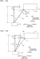
FIG. 11A is a view schematically explaining a state that an upper end of the wiper body makes contact with the lower surface of the head, andFIG. 11B is a view schematically explaining a state that a projection makes contact with the lower surface of the head. - In the following, an ink-jet printer 1 according to an embodiment of the present invention will be explained, with reference to the drawings.
- In
FIG. 1 , the upstream side in a conveying direction of a medium M is defined as the front side of the ink-jet printer 1, and the downstream side in the conveying direction is defined as the rear side of the ink-jet printer 1. Further, a direction which is parallel to a plane or surface (conveyance plane or surface) in which the medium M such as print paper (print sheet, print paper sheet) is conveyed (a plane or surface parallel to the sheet surface ofFIG. 1 ) and which is orthogonal to the conveying direction is defined as a wiping direction. The wiping direction coincides with a width direction of the medium M. As will be described later on, the wiping direction is a direction in which thehead 11 is moved with respect to awiper 100 in a case that a wiping operation is performed by using thewiper 100. One side of the wiping direction corresponds to the left side in a case that the ink-jet printer 1 is seen from the front side (the left side inFIG. 1 ), and the other side of the wiping direction corresponds to the right side in a case that the ink-jet printer 1 is seen from the front side (the right side inFIG. 1 ). Further, a direction orthogonal to the conveyance plane of the medium M (a direction orthogonal to the sheet surface ofFIG. 1 ) is defined as the up-down direction of the ink-jet printer. InFIG. 1 , a side to which the front surface of the sheet is oriented or faces is the upper side, and a side to which the rear surface of the sheet is oriented or faces is the lower side. In the following explanation, the front (front side), the rear (rear side), the left (left side), the right (right side), the up (upper side) and the down (lower side) are appropriately used. - As depicted in
FIG. 1 , the ink-jet printer 1 is provided with acasing 2, aplaten 3, ahead bar 4,conveying rollers head holder 6, amaintenance system 8 and acontroller 10. Note that the ink-jet printer 1 is an example of a "liquid discharge apparatus". The configuration in which thehead bar 4 and themaintenance system 8 are combined is an example of a "head bar system". - As depicted in
FIG. 1 , thehead holder 6 is arranged in thecasing 2 so that thehead holder 6 is movable in the wiping direction. Thehead holder 6 is arranged to sandwich, in the wiping direction, the both sides of theplaten 3. Thehead bar 4 is fixed to thehead holder 6. Thehead bar 4 is arranged at a location above theplaten 3 so that a predetermined spacing distance is formed (defined) between thehead bar 4 and theplaten 3. The medium M which is, for example, paper, etc., is conveyed on the upper surface of theplaten 3. - As depicted in
FIG. 1 , thehead bar 4 is provided with 10 pieces of an ink-jet head 11 (hereinafter simply referred to as the "head(s) 11". The ten heads 11 are arranged to form two rows along the wiping direction. Further, fiveheads 11, among the tenheads 11, which construct each of the two rows are arranged with equal spacing distances therebetween in the wiping direction. The two rows of theheads 11 are arranged to be shifted from each other in the wiping direction. Namely, the fiveheads 11 arranged on the upstream side in the conveying direction (the front side) are arranged to be shifted toward one side in the wiping direction (leftward) with respect to the fiveheads 11 arranged on the downstream side in the conveying direction (the rear side). In other words, the tenheads 11 are arranged in the staggered manner in the wiping direction. In the present embodiment, an ink supplied from a non-illustrated ink supplying part is discharged or ejected from each of theheads 11. - The conveying
roller 5A is arranged on the front side with respect to theplaten 3, and the conveyingroller 5B is arranged on the rear side with respect to theplaten 3. Each of the conveyingrollers platen 3 rearward. Note that the medium M may be a roll-shaped sheet including a supply roll arranged on the upstream side in the conveying direction with respect to theplaten 3, and a recovery roll arranged on the downstream side in the conveying direction with respect to theplaten 3. In such a case, the medium M which is fed out from the supply roll passes on theplaten 3, and then is wound around (is taken up by) the recovery roll. Note that the supply roll may be attached to the conveyingroller 5A, and that the recovery roll may be attached to the conveyingroller 5B. Alternatively, the medium M may be a roll-shaped sheet including only a supply roll arranged on the upstream side in the conveying direction with respect to theplaten 3. In this case, the supply roller may be attached to the conveyingroller 5A. - The
maintenance system 8 is arranged, in the inside of thecasing 2, at a location between theplaten 3 and thehead bar 4 regarding the up-down direction. As depicted inFIG.1 , themaintenance system 8 is mainly provided with twowipers 100, amaintenance base 82, apinion gear 83, arack gear 84, aguide 85, a driving motor 86 (seeFIG. 4 ) and an engaging block 87 (seeFIG. 6 ). In a case that maintenance is performed, thewiper 100 is caused to wipe a lower surface (anozzle surface 41A and a lower surface of a nozzle cover 241 (seeFIG. 2 ) which will be described later on) of each of theheads 11 while moving the head holder 6 (and the head bar 4) along therack gear 84 toward the one side (right side) in the wiping direction. As depicted inFIG. 1 , therack gear 84 extends up to the right side with respect to (beyond) themaintenance base 82. In a case that the maintenance is not performed, thehead bar 4 is arranged at a position at which thehead bar 4 does not interfere with themaintenance base 82 on the left side with respect to the maintenance base 82 (stand-by position, printing position). The detailed configuration of themaintenance system 8 will be described later on. - The
controller 10 is capable of mutually communicating with anexternal apparatus 1000 such as a personal computer, etc. Thecontroller 10 controls the operations of therespective heads 11 included in thehead bar 4, the conveyingrollers maintenance system 8, based on an instruction from theexternal apparatus 1000 or an instruction from a user via an operating part (not depicted) provided on the ink-jet printer 1. - Next, the lower surface of the
head bar 4 and the lower surface of each of theheads 11 will be explained, with reference toFIG. 2 . Note thatFIG. 2 depicts only ahead 11 which is arranged rightmost among the fiveheads 11 arranged on the upstream side in the conveying direction and ahead 11 which is arranged rightmost among the fiveheads 11 arranged on the downstream side in the conveying direction, and remainingheads 11 other than these twoheads 11 are omitted in the illustration. - A bottom surface of each of the
heads 11 faces or is opposite to theplaten 3. Further, anozzle surface 41A in which 1680 pieces of anozzle 11a are opened is included in the bottom surface of each of theheads 11. In thenozzle surface 41A, the 1680nozzles 11a form 24 pieces of a nozzle row arranged side by side in the conveying direction. Furthermore, each of the 24 nozzle rows includes 70 pieces of thenozzle 11a arranged side by side in the wiping direction with equal spacing distances therebetween. Each of the 70nozzles 11a constructing one of the nozzle rows is arranged to be shifted in the wiping direction with respect to one of the 70nozzles 11a constructing another nozzle row adjacent thereto in the conveying direction. In the following explanation, a virtual area which is an area which is on the inner side with respect to an outer edge of thenozzle surface 41A of each of theheads 11 and which includes all thenozzles 11a formed in thenozzle surface 41A in the inside of the area is referred to as anozzle formation area 41B. Further, each of theheads 11 has anozzle cover 241 which is arranged therein and which is configured to cover thenozzle 41A from therebelow so as to surround thenozzle formation area 41B of thenozzle surface 41A (seeFIGs. 2 and9 ). As depicted inFIG. 9 , the lower surface of thenozzle cover 241 protrude downward beyond thenozzle surface 41A. In the following explanation, the lower surfaces of thenozzle surface 41A and thenozzle cover 241 are collectively referred to as the "lower surface" of thehead 11, in some cases. - Ten pieces of an
opening 4A corresponding to the tenheads 11, respectively, are formed in the lower surface of thehead bar 4. The tenopenings 4A are arranged in two rows in the staggered manner along the wiping direction. Fiveopenings 4A included in the tenopenings 4A and constructing each of the two rows are arranged in the wiping direction with equal spacing distances therebetween. As depicted inFIG. 2 , each of theopenings 4A has a size which is substantially same as the lower surface of one of theheads 11; and thenozzle cover 241 and thenozzle surface 41A (nozzle formation area 41B) of each of theheads 11 is exposed from one of theopenings 41A corresponding thereto. Note that in the present embodiment, although not depicted in the drawings, the lower surface of thehead bar 4 is flush with thenozzle surface 41A of each of theheads 11, and a lower end of thenozzle cover 241 of each of theheads 11 projects downward beyond the lower surface of thehead bar 4. Note that it is not necessarily indispensable that the lower surface of thehead bar 4 is flush with thenozzle surface 41A of each of theheads 11. For example, it is allowable that thenozzle surface 41A of each of theheads 11 protrudes downward beyond the lower surface of thehead bar 4. - Next, a
channel unit 42 and anactuator unit 40 constructing each of theheads 11 will be explained, with reference toFIGs. 2 to 4 . Note that since the configurations of thechannel unit 42 and theactuator unit 40 are common to the tenheads 11, the explanation will be given about thechannel unit 42 and theactuator unit 40 in one piece of thehead 11. - As depicted in
FIG. 3 , thechannel unit 42 is formed of a plurality of metal plates and anozzle plate 41 which are stacked in the up-down direction. An ink channel such asindividual channels 12 which includepressure chambers 12a, respectively, a manifold 13, etc., is formed in the plurality of metal plates by the etching. Thenozzle plate 41 is formed, for example, of a polymeric synthetized resin material such as polyimide, etc., and is adhered to a lower surface of the stacked metal plates with an adhesive. A lower surface of thenozzle plate 41 becomes to be the above-describednozzle surface 41A. Note that it is allowable that thenozzle plate 41 is also formed of a metallic material such as stainless steel, etc. - As depicted in
FIG. 3 , theindividual channels 12 each of which communicates with one of thenozzles 11a, and the manifold 13 communicating with theindividual channels 12 are formed in the inside of thechannel unit 42. Although not depicted in the drawings, the manifold 13 extends in the wiping direction (inFIG. 3 , a direction perpendicular to the sheet surface). The ink is supplied, via a non-illustrated ink supply port formed in thechannel unit 42, to the manifold 13 from a non-illustrated ink supplying part which is provided at the outside of thehead 11. - Note that although not depicted in the drawings, 1680 pieces of the
individual channel 12 are arranged so as to form 24 individual channel rows extending in the wiping direction, in corresponds to that the 1680nozzles 11a are arranged so as to form the 24 nozzle rows extending in the wiping direction, as described above. Further, 12 pieces of the manifold 13 are provided on the channel unit 24; each of the 12manifolds 13 communicates with 140individual channels 12, among the 1680individual channels 12, constructing two individual channel rows among the 24 individual channel rows. With this, in the inside of thechannel unit 42, a plurality of ink channels is formed, each of the plurality of ink channel starting from the manifold 13, passing thepressure chamber 12a of one of the plurality ofindividual channels 12, and reaching one of thenozzles 11a. Note that the number (quantity) of the manifold 13 formed in thechannel unit 42 and the number (quantity) of theindividual channel 12 communicating with the manifold 13 are not limited to or restricted by the above-described numbers (quantities). - As depicted in
FIG. 3 , one of thepressure chambers 12a is formed in each of theindividual channels 12, and theactuator unit 40 is arranged at a location above thepressure chambers 12a. Theactuator unit 40 is provided with avibration plate 43 arranged on the upper surface of thechannel unit 42 so as to cover all thepressure chambers 12a, apiezoelectric body 44 arranged to cover the entire surface (entirety) of the upper surface of thevibration plate 43, and 1680individual electrodes 45 each of which is arranged, on the upper surface of thepiezoelectric body 44, at a position facing one of thepressure chambers 12a. As will be described later on, thevibration plate 43 functions as a common electrode. Thevibration plate 43 as the common electrode, each of theindividual electrodes 45, and a part, of thepiezoelectric body 44, which is sandwiched by one of theindividual electrodes 45 and thevibration plate 43 form one piece of a drivingelement 46. Namely, theactuator unit 40 includes 1680 pieces of the drivingelement 46. - The
vibration plate 43 is a metallic plate which has a substantially rectangular shape in a plan view, and is formed of an iron-based alloy such as stainless steel, a copper-based alloy, a nickel-based alloy, or a titanium-based alloy, etc. The upper surface of thevibration plate 43 having the electric conductivity is arranged on the side on which the lower surface of thepiezoelectric body 44 is located. Accordingly, the upper surface of thevibration plate 43 is capable of functioning also as the common electrode. Thevibration plate 43 as the common electrode is connected to a ground wiring of a driver IC 48 (seeFIG. 4 ) which drives theactuator unit 40, and is maintained to be the ground potential at all times. Note that it is not necessarily indispensable that thevibration plate 43 is the metallic plate; for example, it is allowable that thevibration plate 43 is formed of a piezoelectric material which is same as that forming thepiezoelectric body 44, and that a metallic film as the common electrode is formed on the upper surface of thevibration plate 43. - The
piezoelectric body 44 is formed of a piezoelectric material composed primarily of lead zirconate titanate (PZT) which is a solid solution of lead titanate and lead zirconate and which is a ferroelectric substance. Thepiezoelectric body 44 is polarized in a thickness direction (up-down direction) at least at an area facing thepressure chamber 12a (a part sandwiched between theindividual electrode 45 and the vibration plate 43). In the present embodiment, a layer of the piezoelectric body (piezoelectric layer) which is formed continuously across the plurality ofpressure chambers 12a is formed on the upper surface of thevibration plate 43. It is allowable, however, that 1680 pieces of an independent (separate)piezoelectric body 44 are provided, each corresponding to one of the 1680 pieces of thepressure chamber 12a. - As depicted in
FIG. 3 , each of theindividual electrodes 45 is arranged at an area, of the upper surface of thepiezoelectric body 44, which faces one of thepressure chambers 12a. Each of theindividual electrodes 45 is electrically connected to the driver IC 48 (seeFIG. 4 ) mounted on a non-illustrated flexible wiring (COF), via a signal line 34 (seeFIG. 4 ). As depicted inFIG. 4 , thedriver IC 48 is electrically connected to thecontroller 10. Thedriver IC 48 applies a driving pulse signal to theindividual electrode 45 of the drivingelement 46, based on a signal transmitted from thecontroller 10. With this, thedriver IC 48 applies either one of a predetermined driving potential and the ground potential selectively to each of theindividual electrodes 45. - Next, an explanation will be given about an action of the driving
element 46 of theactuator unit 40 at a time of ink discharge (ink ejection). In a case that the predetermined driving potential is applied from thedriver IC 48 to a certainindividual electrode 45 included in theindividual electrodes 45, a potential difference is generated between the certainindividual electrode 45 to which the driving potential is applied and thevibration plate 43 as the common electrode and maintained at the ground potential. With this, an electric field in the thickness direction is generated at the part, of thepiezoelectric body 44, sandwiched between the certainindividual electrode 45 and thevibration plate 43. The direction of the electric filed is parallel to the polarization direction of thepiezoelectric body 44. Accordingly, due to this electric field, an area (active area), of thepiezoelectric body 44, which faces the certainindividual electrode 45 contracts in a plane direction orthogonal to the thickness direction. Here, thevibration plate 43 which is on the lower side of thepiezoelectric body 44 is fixed to thechannel unit 42. Accordingly, accompanying with the active area, of thepiezoelectric body 44, which is positioned on the upper surface of thevibration plate 43 contracting in the plane direction, a part of thevibration plate 43 which covers thepressure chamber 12a is deformed so as to project toward thepressure chamber 12a (unimorph deformation, seeFIG. 3 ). In this situation, since the volume inside thepressure chamber 12a is reduced, the pressure of the ink inside acertain pressure chamber 12a, among thepressure chambers 12, corresponding to the certainindividual electrode 45 is increased, thereby discharging the ink from anozzle 11a, among thenozzles 11a, communicating with thecertain pressure chamber 12a. - Next, an explanation will be given about the schematic electric configuration of the ink-jet printer 1, with reference to
FIG. 4 . Thecontroller 10 is electrically connected to each of theheads 11. Thecontroller 10 is mainly provided with a CPU (Central Processing Unit) 101, a ROM (Read Only Memory) 102, a RAM (Random Access Memory) 103, and anon-volatile memory 104. TheROM 102 stores a program(s), a variety of kinds of data, etc., with which the CPU controls a variety of kinds of operations. TheRAM 103 is used as a memory area configured to temporarily store data, signal, etc., to be used by theCPU 101 for executing the program, or is used as a work space for executing data processing. It is allowable to use, as thenon-volatile memory 104, for example, an EEPROM (Electrically Erasable Programmable Read-Only Memory). Note that it is allowable to use a MPU (Microprocessor Unit) or a FPGA (Field Programmable Gate Array), rather than using theCPU 101. - As depicted in
FIG. 4 , each of theheads 11 has aFPGA 20 and thedriver IC 48, in addition to theactuator unit 40 including the 1680driving elements 46. TheFPGA 20 is connected to thedrive IC 48 by awiring 33 for control signal. Further, thedriver IC 48 is connected to each of the drivingelements 46 by awiring 48 for driving signal. - In a case that the
controller 10 receives image data from theexternal apparatus 1000, theFPGA 20 outputs a control signal via thewiring 33 for control signal, under the control by thecontroller 10, thedriver IC 48 generates a driving signal for driving theactuator unit 40 based on the control signal inputted from theFPGA 20, and outputs the generated driving signal to theactuator unit 40 via thewiring 34 for driving signal. - Further, a
certain driving element 46, among the drivingelements 46, is driven based on the driving signal supplied from thedriver IC 48, the ink is thereby discharged from acertain nozzle 11a, among thenozzles 11a, corresponding to thecertain driving element 46, in an amount corresponding to the driving signal. - Furthermore, the
controller 10 is electrically connected to a conveyingmotor 51, and controls the driving of the conveyingmotor 51 to thereby control the conveyance of the medium M by the conveyingrollers controller 10 is electrically connected to the drivingmotor 86, and controls the driving of the drivingmotor 86 to thereby control the movement of thehead bar 4 in the wiping direction via thepinion gear 83. - Next, the
maintenance system 8 provided on the ink-jet printer 1 according to the present embodiment will be explained. - As depicted in
FIGs. 1 ,5 and7 , therack gear 84 extends in the wiping direction. Therack gear 84 is arranged in the inside of the casing 2 (seeFIG. 1 ). As depicted inFIG. 5 , teeth meshing or engaging with thepinion gear 83 are formed in the lower surface of therack gear 84. As depicted inFIG. 7 , a length in the wiping direction of therack gear 84 is longer than a length in the wiping direction of an area, of thehead bar 4, in which the tenheads 11 are arranged (hereinafter referred to as a "head arrangement area"). - As depicted in
FIG. 1 , theguide 85 extends in the wiping direction, and is arranged in the inside of thecasing 2. As depicted inFIG. 6 , theguide 85 is arranged at a location below therack gear 84 and thehead holder 6.Guide grooves 85A are formed in side surfaces, respectively, which are on the both sides in the conveying direction of theguide 85. A cross sectional shape of each of theguide grooves 85 is substantially rectangular, and each of theguide grooves 85A extends in the wiping direction (direction perpendicular to the sheet surface ofFIG. 6 ). Note that as depicted inFIG. 7 , a length in the wiping direction of theguide 85 is also longer than the length in the wiping direction of the head arrangement area in thehead bar 4. - The
maintenance base 82 has a shape of a rectangular parallelepiped. As depicted inFIG. 7 , a length in the conveying direction of themaintenance base 82 is longer than a length in the conveying direction of the head arrangement area in thehead bar 4. Further, as depicted inFIG. 6 , apinion gear 83 which protrudes rearward is provided on a side surface on one side in the conveying direction (rear side) of thehead holder 6, and the drivingmotor 86 connected to arotation shaft 83A of thepinion gear 83 is fixed to the inside of themaintenance base 82. As depicted inFIGs. 5 and 6 , therotation shaft 83A of thepinion gear 83 extends in the conveying direction, and teeth meshing with the teeth of therack gear 84 are formed in a circumferential surface of thepinion gear 83. Further, an engagingblock 87 is provided on a location, in the lower surface of thehead holder 6, which is on the one side in the conveying direction (rear side). The engagingblock 87 engages with theguide grooves 85A of theguide 85, while thepinion gear 83 meshes or engages with therack gear 84, thereby supporting thehead holder 6. Note that the positions in the up-down direction of therack gear 84, theguide 85 and thehead holder 6 can be adjusted to a wiping position and to a retreating (retracting) position, by a non-illustrated lifting and lowering mechanism. The wiping position is a position at which anupper end 111 of the wiper 100 (to be described later on) is located above thenozzle surface 41A (nozzle formation area 41B) of thehead 11. The retreating position is a position at which theupper end 111 of thewiper 100 is located below thenozzle surface 41A (nozzle formation area 41B) of thehead 11. - As depicted in
FIG. 1 , the twowipers 100 are attached to the upper surface of themaintenance base 82. Each of the twowipers 100 includes a member which is integrally formed by an EPDM rubber (awiper body 110, abase part 120 and aprojection 130 which will be described later on). The EPDM rubber has the hardness of not less than 70 degrees, and has a property which is less likely to swell by the ink. The shape of each of the twowipers 100 will be described later on. As depicted inFIGs. 1 and7 , positions in the wiping direction of the twowipers 100 are shifted from each other. Specifically, a wiper 100 (hereinafter referred to as a "wiper 100A") included in the twowipers 100 and arranged on the upstream side in the conveying direction is arranged to shift to the one side in the wiping direction (to the left side, leftward) with respect to a wiper 100 (hereinafter referred to as a "wiper 100B") included in the twowipers 100 and arranged on the downstream side in the conveying direction. Further, as depicted inFIG. 7 , thewiper 100A is attached to the upper surface of themaintenance base 82 so that thenozzle formation area 41B of each of the five heads 11 on the upstream side in the conveying direction (front side) is positioned between the both ends in the conveying direction of thewiper 100A. Similarly, thewiper 100B is attached to the upper surface of themaintenance base 82 so that thenozzle formation area 41B of each of the five heads 11 on the downstream side in the conveying direction (rear side) is positioned between the both ends in the conveying direction of thewiper 100B. - In a case that the
pinion gear 83 rotates in normal and reverse directions in accordance with the driving of the drivingmotor 86, thehead holder 6 thereby moves in a reciprocal manner along therack gear 84 and theguide 85 in the wiping direction. Thehead holder 6, the drivingmotor 86, thepinion gear 83, therack gear 84 and theguide 85 correspond to a "driving part" of the present invention. As will be described later on, in a state that thehead holder 6 is moved to the maintenance position by the non-illustrated liftin-lowering mechanism, thehead holder 6 is moved toward the right side in the wiping direction, thereby making it possible to perform a wiping operation of wiping the ink adhered to thenozzle formation area 41B of thehead 11. In this situation, as depicted inFIG. 7 , the upper end 111 (seeFIGs. 8A and 8B ) of thewiper 100A successively makes contact with thenozzle formation areas 41B of the respective fiveheads 11 on the upstream side in the conveying direction, and wipes off the ink adhered to thenozzle formation areas 41B. Similarly, the upper end 111 (seeFIGs. 8A and 8B ) of thewiper 100B successively makes contact with thenozzle formation areas 41B of the respective fiveheads 11 on the downstream side in the conveying direction, and wipes off the ink adhered to thenozzle formation areas 41B. Namely, each of thewiper 100A and thewiper 100B is capable of wiping a plurality of pieces of thenozzle formation area 41B which is aligned in the wiping direction. In themaintenance system 8 of the present invention, since each of thewipers 100 is capable of wiping the plurality of pieces of the nozzle formation area in such a manner, it is possible to wipe the plurality of nozzle formation areas efficiently, and to shorten the time required for the maintenance. - Next, the shape of the
wiper 100 will be explained, with reference toFIGs. 8A, 8B ,9 ,10A and 10B . As depicted inFIGs. 8A and 8B , thewiper 100 is provided with awiper body 110, abase part 120, twoprojections 131 and a fixing member 140 (seeFIGs. 7 ,10A and 10B ). Thewiper body 110 is a plate-like member elongated in the conveying direction. Thewiper body 110 has a thickness in the wiping direction which becomes thinner further toward the upper side. A plurality ofgrooves 115 extending in the up-down direction is formed in a surface 113 (hereinafter referred to as a "first surface 113") on the one side in the wiping direction (left side) of thewiper body 110. A plurality ofgrooves 116 extending in the up-down direction and a plurality ofgrooves 117 extending in the conveying direction are formed in a surface 114 (hereinafter referred to as a "second surface 114") on the other side in the wiping direction (right side) of thewiper body 110. Steppedparts 112 of which height in the up-down direction is lower than theupper end 111 are formed, respectively, on both sides in the conveying direction of theupper end 111 of thewiper body 110. Theupper end 111 is an example of a "first area" of the present invention, and the steppedparts 112 are each an example of a "second area" of the present invention. In a case that thewiper 100 is at the wiping position, theupper end 111 makes contact with thenozzle surface 41 of thehead 11, and the steppedparts 112 make contact with thenozzle cover 241 of thehead 11, as will be described later on. - As depicted in
FIG. 8A , thebase part 120 is provided on a lower end of thefirst surface 113 of thewiper body 110. The thickness (length in the wiping direction) of thebase part 120 is greater than the thickness of thewiper body 110. A projectingpart 121 which projects in the up-down direction is formed at a central part in the conveying direction of thebase part 120. - As depicted in
FIG. 8B , twoprojections 130 which project toward the other side (right side) in the wiping direction are formed in thesecond surface 114 of thewiper body 110. In the present embodiment, the twoprojections 130 are arranged in the conveying direction with a spacing distance therebetween so that an inner side end in the conveying direction of each of the twoprojections 130 is located at a position which is same as one of the ends on the both sides in the conveying direction of theupper end 111 of the wiper body 110 (seeFIG. 9 ). In other words, each of the twoprojections 130 projects, in thesecond surface 114 of thewiper body 110, from one of the steppedparts 112 toward the other side in the wiping direction (right side). Each of theprojections 130 has a base 131 having a substantially rectangular parallelepiped shape and extending perpendicularly from thesecond surface 114, and a supportingpart 132 which spreads downward from a lower end of thebase 131. Note that anupper surface 131a of thebase 131 is flush with one of the steppedparts 112 of thewiper body 110. As will be described later on, in a case that thewiper 100 is at the wiping position, theupper surface 131a of thebase 131 makes contact with thenozzle cover 241 of thehead 11. Theupper surface 131a of thebase 131 is an example of a "contact surface" of the present invention. - As depicted in
FIG. 8B , a thickness in the conveying direction of thebase 131 is greater than a thickness in the conveying direction of the supportingpart 132. An upper end of the supportingpart 132 is continuously connected to a lower end of thebase 131, and a left end of the supportingpart 132 is continuously connected to the second surfaced 114 of thewiper body 110. A lower end of the supportingpart 132 is located at a position lower than the center in the up-down direction of thesecond surface 114. The supportingpart 132 has a trapezoidal shape as seen in the conveying direction, and a length in the wiping direction of the supportingpart 132 becomes longer further downward from the lower end of thebase 131. Further, a length in the up-down direction of the supportingpart 132 becomes shorter as separating further away from thesecond surface 114 of thewiper body 110 toward the right side. - As depicted in
FIG. 9 , a width L1 in the conveying direction of theupper end 111 of thewiper body 110 is greater than a length L2 in the conveying direction of thenozzle formation area 41B of each of theheads 11, and is slightly smaller than an inner width L3 of thenozzle cover 241. Accordingly, in a case that thewiper 100 is positioned at the wiping position, theupper end 111 of thewiper body 100 is capable of making contact with thenozzle surface 41B, without interfering with thenozzle cover 241. Further, the width L1 in the conveying direction of theupper end 111 of thewiper body 100 is greater than the length L2 in the conveying direction of thenozzle formation area 41B of each of theheads 11. Accordingly, during the wiping operation, theupper end 111 of thewiper body 110 is capable of wiping the entirety of thenozzle formation area 41B. Furthermore, a depth 1 in the up-down direction of the steppedparts 112 is substantially same as a height H in the up-down direction of thenozzle cover 241. Moreover, as described above, theupper surface 131a of thebase 131 is flush with the steppedparts 112 of thewiper body 110. Accordingly, in the case that thewiper 100 is positioned at the wiping position, the steppedparts 112 of thewiper body 100 and theupper surface 131a of the base 131 are capable of making contact with thenozzle cover 241. Further, a width L4 in the conveying direction of the steppedparts 112 and a width L5 in the conveying direction of theupper surface 131a of the base 131 are greater than a length L6 in the conveying direction of thenozzle cover 241. Accordingly, at the time of the wiping, the steppedparts 112 and theupper surface 131a of each of theprojections 130 are capable of wiping the entirety of thenozzle cover 241. - The fixing
member 140 is a member configured to fix thewiper body 110 to themaintenance base 82. As depicted inFIG. 10B , the fixingmember 140 is provided with afirst member 141 and asecond member 145 which are fixable to thefirst member 141. Note that thefirst member 141 is fixed to the maintenance base 82 (seeFIG. 7 ). As depicted inFIG. 10A , thefirst member 141 is a member having a cross section which is substantially a shape of a letter "L", and elongated in the conveying direction. Two projectingbars first member 141. The projectingbar 142 is positioned above the projectingbar 143, and the projectingbars bar 142 is formed to have a discontinuedgap 144 at a part in the conveying direction thereof. As depicted inFIG. 10B , it is possible to fix thewiper body 110 to the fixingmember 140 by causing thebase member 120 provided on the lower part of thewiper body 110 to be sandwiched between thefirst member 141 and thesecond member 145 in a state that thebase part 120 is inserted between the two projectingbars base part 120 is inserted between the two projectingbars wiper body 110 might be deviated in the up-down direction. Further, although not depicted in the drawings, the projectingpart 121 of thebase part 120 engages with thegap 144 provided on the projectingbar 142. With this, there is not such a fear that thewiper body 110 might be deviated in the conveying direction. - Next, the deformation of the
wiper 100 during the wiping operation will be explained, with reference toFIGs. 11A and 11B . - As depicted in
FIG. 11A in a dotted line, in a case that thewiper body 110 and theprojection 130 do not make contact with the lower surface of thehead 11, thewiper body 110 stands vertically with respect to themaintenance base 82 so that thewiper body 110 is parallel to the up-down direction. A length L in the up-down direction (hereinafter referred to as a height L) of thewiper body 110 is greater than the distance in the up-down direction between themaintenance base 82 and thenozzle surface 41A of thehead 11. In the case that thewiper body 110 do not make contact with the lower surface of thehead 11, thewiper body 110 and thehead 11 overlap with each other in the up-down direction by an amount corresponding to a length LAP. Namely, theupper end 111 of thewiper body 110 is located above thenozzle surface 41A of thehead 11 by the length LAP. In this situation, a length of a part, which is included in thewiper body 110 and which does not overlap with thehead 11 in the up-down direction, can be expressed as: length L - LAP. Note that the distance in the up-down direction between theupper end 111 of thewiper body 110 and theprojection 130 is referred to as a distance 1. As described above, since theupper surface 131a of theprojection 130 and the steppedparts 112 are flush with each other, the distance 1 corresponds to the depth in the up-down direction of the stepped parts 112 (seeFIG. 9 ). - As depicted in a solid line in
FIG. 11A , in a case that theupper end 111 of thewiper body 110 makes contact with the nozzle surface 141A, thewiper body 110 is deformed to be inclined by an angle θ1 toward the other side in the wiping direction (right side), as compared with the case that theupper end 111 of thewiper body 110 does not make contact with the nozzle surface 141A. Note that the angle θ1 can be expressed as: θ1 = arccos ((L-LAP)/L)[rad]. Note that since theprojection 130 projects perpendicularly from thewiper body 110 toward the other side in the wiping direction (right side), theprojection 130 does not make contact with the lower surface of thehead 11 in a case that theupper end 111 of thewiper body 110 makes (is making) contact with thenozzle surface 41A. In other words, in a case that thewiper body 110 makes (is making) contact with the nozzle surface 31A of thehead 11 and is thereby (being) deformed, theprojection 130 does not hinder thewiper body 110 from being deformed. - Here, such a case is presumed that the
projection 130 is not provided on thewiper 100. In a case that thewiper 100 moves, with respect to thehead 11, toward the one side in the wiping direction (left side) and that theupper end 111 of thewiper body 110 is separated from thenozzle surface 41A, thewiper body 110 is abruptly restored to a parallel state in which thewiper body 110 is parallel to the up-down direction. Namely, thewiper body 110 is consequently restored to be inclined by the angle θ1 toward the one side in the wiping direction (left side). In this situation, there is such a fear that the ink which has been wiped from the nozzle surface 41a by the wiping operation and adhered to thefirst surface 113 of thewiper body 110 might be scattered in the surrounding due to the abrupt restoration of thewiper body 110. - In view of this, the
projection 130 is provided on thewiper 100 in the present embodiment. In this case, as depicted by the solid line inFIG. 11B , in the case that thewiper 100 moves, with respect to thehead 11, toward the one side in the wiping direction (left side) and that theupper end 111 of thewiper body 110 is separated from thenozzle surface 41A, theprojection 130 makes contact with the lower surface of the head 11 (for example, the lower surface of the nozzle cover 241) before thewiper body 110 becomes to be parallel to the up-down direction. With this, in an instant that theupper end 111 of thewiper body 110 is separated from thenozzle surface 41A, the wiper body is restored toward the one side in the wiping direction (left side) only by an angle θ2 (θ2 < θ1), rather than by the angle θ1. Here, the angle θ2 can be expressed as: θ2 = arccos ((L-1)/L)[rad], Further, provided that a distance along theprojection 130 between thewiper body 110 and a contact point between theprojection 130 and thehead 11 in the case that theprojection 130 makes contact with the lower surface of thehead 11 is expressed as "X", the X can be expressed as: X = L·sin θ2. The distance X corresponds to a height of theprojection 130 from thewiper body 110 which is required in a case of determining the height L of thewiper body 110, the overlap LAP in the up-down direction between thewiper body 110 and thenozzle surface 41A of thehead 11 and the distance 1 in the up-down direction between theupper end 111 of thewiper body 110 and theprojection 130. - In a case that the
wiper 100 moves further toward the one side in the wiping direction (left side) with respect to thehead 11 and that theprojection 130 is separated from the lower surface of thehead 11, thewiper body 110 is restored toward the one side in the wiping direction (left side) further only by an angle θ3 (θ3 = θ1 - θ2). With this, thewiper body 111 is restored to the state of being parallel to the up-down direction. In such a manner, thewiper body 110 is restored gradually in the two phases after theupper end 111 of thewiper body 110 is separated from thenozzle surface 41A. With this, occurrence of such a situation that the ink which has been wiped from the nozzle surface 41a by the wiping operation and adhered to thefirst surface 113 of thewiper body 110 is scattered in the surrounding due to the abrupt restoration of thewiper body 110 is lowered. - Note that according to the calculation by the inventors, it is found out that in a case that the height L of the
wiper body 110 is 10.5 mm, the overlap LAP in the up-down direction between thewiper body 110 and thenozzle surface 41A of thehead 11 is 1.5 mm, and the distance 1 in the up-down direction between theupper end 111 of thewiper body 110 and theprojection 130 is 0.4 mm, the angle θ1 is 31.0°, the angle θ2 is 15.9° and the angle θ3 is 15.1°; and that the required height X of theprojection 130 from thewiper body 110 is 2.87 mm. Further, it is found out that in a case that the height L of thewiper body 110 is 10.5 mm, the overlap LAP in the up-down direction between thewiper body 110 and thenozzle surface 41A of thehead 11 is 1.0 mm, and the distance 1 in the up-down direction between theupper end 111 of thewiper body 110 and theprojection 130 is 0.4 mm, the angle θ1 is 25.2°, the angle θ2 is 15.9° and the angle θ3 is 9.3°; and that the required height X of theprojection 130 from thewiper body 110 is 2.87 mm. Furthermore, it is found out that in a case that the height L of thewiper body 110 is 10.5 mm, the overlap LAP in the up-down direction between thewiper body 110 and thenozzle surface 41A of thehead 11 is 0.5 mm, and the distance 1 in the up-down direction between theupper end 111 of thewiper body 110 and theprojection 130 is 0.4 mm, the angle θ1 is 17.8°, the angle θ2 is 15.9° and the angle θ3 is 1.9°; and that the required height X of theprojection 130 from thewiper body 110 is 2.87 mm. In such a manner, it is found out that by fixing the height X of the wiper body and by changing the value of the overlap LAP in the up-down direction between thewiper body 110 and thenozzle surface 41A of thehead 11, the angles θ1 and θ2 change as described above. - In the above-described embodiment, the
head 11 has the lower surface including thenozzle surface 41A in which thenozzles 11a are opened. Thewiper 100 is configured to make contact with thenozzle surface 41A of thehead 11 and to wipe thenozzle surface 41A. Thehead holder 6, the drivingmotor 86, theinion gear 83, therack gear 84 and theguide 85 are collectively referred to as the driving part. By using the driving part, it is possible to move the head holder 6 (head 11) so that thewiper 100 moves toward the one side in the wiping direction (left side) relative to (with respect to) thehead 11 in the state that thewiper 100 makes contact with thenozzle surface 41A. Note that the present invention is not necessarily limited to a configuration wherein thehead 11 moves in the wiping direction in the state that thewiper 100 is fixed. It is allowable that thewiper 100 is configured to move in the wiping direction in a state that thehead 11 stands still, or that both of thehead 11 and thewiper 100 are configured to move in the wiping direction. - The
wiper 100 is provided with thewiper body 110 having theupper end 111 which is a wiping part configured to wipe thenozzle surface 41A, and theprojection 130 which projects from thewiper body 110 toward the other side in the wiping direction (right side). After theupper end 111 of thewiper body 110 is separated from the end part on the one side in the wiping direction (left side) of thenozzle surface 41A, theprojection 130 makes contact with the lower surface of the head 11 (the lower surface of the nozzle cover 241). - After the
upper end 111 of thewiper body 100 is separated from the end part on the one side in the wiping direction (left side) of thenozzle surface 41A, theprojection 130 makes contact with the lower surface of the head 11 (the lower surface of the nozzle cover 241), which in turn suppress occurrence of such a situation that the deformation of thewiper body 110 is restored all at once. With this, the restoring speed of thewiper body 110 is suppressed to thereby suppress the occurrence of such a situation that the ink which has been wiped from the nozzle surface 41a by the wiping operation and adhered to thefirst surface 113 and theupper end 111 of thewiper body 110 is scattered in the surrounding due to the abrupt restoration of thewiper body 110. By providing theprojection 130 as described above on thewiper 100, the restoring force of thewiper body 110 is suppressed. Accordingly, there is no need to provide a member which is different from thewiper 100 separately so as to suppress the restoring force of thewiper body 110, and to suppress the manufacturing cost. Further, since theprojection 130 is formed in thesecond surface 114 on the other side in the wiping direction (right side), theprojection 130 does not affect the deformation of thewiper body 110 in a case that thewiper body 110 wipes thenozzle surface 41A. Accordingly, even in a case that theprojection 130 is formed so as to suppress the restoring force of thewiper body 110, there is not such a fear that the wiping performance of thewiper 100 might be lowered. - In the above-described embodiment, the
wiper body 110 and theprojection 130 are produced by being integrally formed. With this, it is possible to suppress the increase in the manufacturing cost of thewiper 130. - In the above-described embodiment, the
projection 130 is provided with theupper surface 131a of the base 131 which extends perpendicularly from thesecond surface 114 on the other side in the wiping direction (right side) of thewiper body 110, and makes contact with the lower surface of thenozzle cover 241 of thehead 11. With this, it is possible to wipe the lower surface of thenozzle cover 241 by using theupper surface 131a of thebase 131 of theprojection 130. - In the above-described embodiment, the supporting
part 132 is provided on theprojection 130, at the location below thebase 131. The upper end of the supportingpart 132 is continuously connected to the lower end of thebase 131, and the left end of the supportingpart 132 is continuously connected to thesecond surface 114 of thewiper body 110. The supportingpart 132 has a shape of trapezoid as seen in the conveying direction, and the length in the wiping direction of the supportingpart 132 becomes longer further downward from the lower end of thebase 131. By adopting such a configuration, it is possible to support thebase 131 of theprojection 130 more stably by the supportingpart 132. - In the above-described embodiment, the
wiper body 110 has theupper end 111 as the wiping part configured to wipe thenozzle surface 41A and thefirst surface 113. Accordingly, the ink wiped from thenozzle surface 41A by the wiping operation adheres to thefirst surface 113 of thewiper body 110. Since the plurality ofgrooves 115 extending in the up-down direction is formed in thefirst surface 113 of thewiper body 110, it is possible to move the ink adhered to thefirst surface 113 downward via the plurality ofgrooves 115. With this, it is possible to suppress the occurrence of such a situation that the ink adhered to thefirst surface 113 is scattered in the surrounding in a case that the deformation of thewiper body 110 is restored. - In the above-described embodiment, the two
projections 130 which project from thesecond surface 114 of thewiper body 110 are provided on thewiper 100. The twoprojections 130 are arranged with the spacing distance in the conveying direction orthogonal to the wiping direction. Since the twoprojections 130 are provided on thewiper 100 in such a manner, it is possible to wipe two location at a time by using the twoprojections 130. - Further, the two
projections 130 make contact with thenozzle cover 241, rather than making contact with thenozzle surface 41A in the lower surface of thehead 11. With this, it is possible to wipe thenozzle cover 241 at the same time with the wiping of thenozzle surface 41A, rather than wiping only thenozzle surface 41A. - In the above-described embodiment, the
wiper body 110 has theupper end 111 making contact with thenozzle surface 41A at the time of the wiping, and the steppedparts 112 of which height in the up-down direction is lower than that of theupper end 111. At the time of the wiping, the steppedparts 112 make contact with thenozzle cover 241 which covers thenozzle surface 41A from therebelow. With this, it is possible to perform wiping for thenozzle surface 41A and thenozzle cover 241 at a time during the wiping. - In the present embodiment, in a case that the
wiper 100 moves toward the one side in the wiping direction (left side) relative to thehead 11 and that theupper end 111 of thewiper body 110 is separated from thenozzle surface 41A, theprojections 130 make contact with the lower surface of thenozzle cover 241 before thewiper body 110 becomes to be parallel to the up-down direction. In this case, since theprojections 130 do not collide against thenozzle surface 41A, there is not a fear that theprojections 130 might damage thenozzle surface 41A. - In the present embodiment, the plurality of
grooves 116 extending in the up-down direction and the plurality ofgrooves 117 extending in the conveying direction are formed in thesecond surface 114 of thewiper body 110. The plurality ofgrooves 116 has the effect of moving the ink adhered to thesecond surface 114 downward, similarly to the plurality ofgrooves 115. Further, by providing the plurality ofgrooves 117 on thesecond surface 114, it is possible to make thewiper body 110 to be easily deformable. - In the present embodiment, the two projecting
bars base part 120 of thewiper 100 are formed in the fixingmember 140. Further, the projectingbar 142 of the fixingpart 142 is provided with thegap 144 configured to fit to the projectingpart 121 of thebase part 120 of thewiper 100. Since thebase part 120 is inserted between the two projectingbars wiper body 110 might be deviated in the up-down direction. Further, since the projectingpart 121 of thebase part 120 engages with thegap 144 formed in the projectingbar 142, there is not such a fear that thewiper body 110 might be deviated in the conveying direction. - In the present embodiment, each of the
first surface 113 and thesecond surface 114 of thewiper body 110 is a broad wide surface expanding in the conveying direction and the up-down direction. The thickness in the wiping direction of thewiper body 110 becomes thinner further upward. Further, the twoprojections 130 are arranged to be apart in the both sides in the conveying direction of thesecond surface 114. Each of theprojections 130 has thebase 131 and the supportingpart 132. The lower end of the supportingpart 132 is located below the center in the up-down direction of thesecond surface 114 of thewiper body 110. Further, the length in the conveying direction of each of theprojections 130 is greater than the thickness in the conveying direction of thewiper body 110. - Also in such a case, since after the
upper end 111 of thewiper body 110 is separated from the end part on the one side in the wiping direction (left side) of thenozzle surface 41A, theprojections 130 make contact with the lower surface of the head 11 (the lower surface of the nozzle cover 241), it is possible to suppress occurrence of such a situation that the deformation of thewiper body 110 is restored all at once. This suppresses the occurrence of such a situation that the ink which has been wiped from thenozzle surface 41A by the wiping operation and adhered to thefirst surface 113 and theupper end 111 of thewiper body 110 is scattered in the surrounding due to the abrupt restoration of thewiper body 110. Further, by providing theprojections 130 as described above on thewiper 100, the restoring force of thewiper body 110 is suppressed. Accordingly, there is no need to provide a member which is different from thewiper 100 separately so as to suppress the restoring force of thewiper body 110, and thus it is possible to suppress the manufacturing cost. Further, since theprojections 130 are formed in thesecond surface 114 on the other side in the wiping direction (right side), theprojections 130 do not affect the deformation of thewiper body 110 in a case that thewiper body 110 wipes thenozzle surface 41A. Accordingly, even in a case that theprojections 130 are formed so as to suppress the restoring force of thewiper body 110, there is no such a fear that the wiping performance of thewiper 100 might be lowered. - In the foregoing, the embodiment of the present invention has been explained. The present invention, however, is not limited to or restricted by the above-described embodiment; various kinds of change can be made to the present invention within the range described in the claims. In the following, a modification of the above-described embodiment will be explained.
- In the above-described embodiment, the
wiper body 110, thebase part 120 and theprojections 130 of thewiper 100 are integrally formed of the EPDM rubber. The present embodiment, however, is not limited to or restricted by this. For example, it is allowable to form thewiper body 110, thebase part 120 and theprojections 130 of a perfluoro fluorine rubber, rather than forming thewiper body 110, thebase part 120 and theprojections 130 of the EPDM rubber. Further, it is not necessarily indispensable that thewiper body 110, thebase part 120 and theprojections 130 are integrally formed; it is allowable to form thewiper body 110, thebase part 120 and theprojections 130 by combining separate (individual) members. Furthermore, although the hardness of thewiper member 100 is preferably not less than 70 degrees, it is not necessarily indispensable that the hardness of thewiper body 110 is not less than 70 degrees. - In the above-described embodiment, although the two pieces of the
projection 130 are provided, the present invention is not necessarily limited to such an aspect. For example, it is allowable that the number (quantity) of theprojection 130 may be 1 (one), or not less than 3. Further, the position in the conveying direction of theprojection 130 may also be changed as appropriate. - In the above-described embodiment, although the
upper surface 131a of thebase 131 of theprojection 130 and the steppedpart 112 are formed to be flush with each other with respect to the up-down direction, the present invention it not limited to such an aspect. For example, it is allowable that theprojection 130 is arranged so that theupper surface 131a is located below the steppedpart 112. Further, in the above-described embodiment, theupper surface 131a of thebase 131 and the steppedpart 112 are configured to make contact with thenozzle cover 241 and to wipe thenozzle cover 241. The present invention, however, is not limited to such an aspect. For example, it is not necessarily indispensable that thenozzle cover 241 is provided on thehead 11. In such a case, it is allowable that the steppedpart 112 is not provided, and that theupper surface 131a of thebase 131 is configured to make contact with thenozzle surface 41A. - In the above-described embodiment, although the ink-jet printer 1 is provided with one piece of the
head bar 4, the number (quantity) of thehead bar 4 may be plural. Note that the number of thehead 11 provided on thehead bar 4 is not limited to 10 (ten). Further, the number of thenozzle 11a opened in thenozzle surface 41A, the number of the nozzle row, and the number of thenozzle 11a forming each of the nozzle rows are not limited to the numbers, respectively, as described above. Furthermore, it is also possible to change the number and the arrangement of theindividual channel 12 and the drivingelement 46 as appropriate, in accordance with the number and the arrangement of thenozzle 11a. - It is allowable that the position at which the wiper 110A is attached is not shifted in the wiping direction with respect to the position at which the
wiper 100B is attached. Namely, in themaintenance base 82, the attachment position of thewiper 100A and the attachment position of thewiper 100B may be aligned in the wiping direction. - In the above-described embodiment, although the
wiper 100A and thewiper 100B are provided as the separate members, the present invention is not limited to this. For example, thewiper 100A and thewiper 100B may be formed or molded as one member by connecting an end part on the one side in the conveying direction (end of the rear side) of thewiper 100A and an end part on the other side in the conveying direction (end part on the front side) of thewiper 100B are connected by a connecting part. - In the above-described embodiment, the
head holder 6 is supported by therack gear 84 and theguide 85 which are arranged on the one side in the conveying direction (rear side) with respect to thehead holder 6, the present invention in not limited to this. For example, it is allowable to further provide a guide extending in the wiping direction on the other side in the conveying direction (front side) with respect to thehead holder 6, and to support an end part on the other side in the conveying direction of thehead holder 6 with this guide. In this case, it is also allowable to provide, on the end part on the other side in the conveying direction on the lower surface of thehead holder 6, a roller which is slidable along the added guide. - Further, it is allowable to arrange an absorbing member, for example such as a sponge, etc., configured to absorb the ink adhered to the
first surface 113 of thewiper body 110, on the fixingmember 140 of thewiper 100. - In the above-described embodiment, the
channel unit 42 of each of theheads 11 is provided with theactuator unit 40 having the 1680driving elements 46 corresponding, respectively to the 1680individual channels 12. The present invention, however, is not limited to such an aspect. For example, it is allowable to provide, on thechannel unit 42, a heater configured to bump the ink inside each of theindividual channels 12 so as to discharge the ink from thenozzle 11a, instead of theactuator unit 40. - The medium M is not limited to the paper such as the print paper; the medium M may be, for example, a film formed of a resin, cloth, etc.
-
- 1
- ink-jet printer
- 4
- head bar
- 5A, 5B
- conveying roller
- 8
- maintenance system
- 10
- controller
- 11
- ink-jet head
- 11a
- nozzle
- 12
- individual channel
- 12a
- pressure chamber
- 41A
- nozzle surface
- 41B
- nozzle formation area
- 100
- wiper
- 110
- wiper body
- 120
- base part
- 130
- projection
Claims (13)
- A liquid discharge apparatus characterized by comprising:a head including a lower surface including a nozzle surface in which a nozzle is opened;a wiper configured to make contact with the nozzle surface of the head and to wipe the nozzle surface; anda driving part configured to drive at least one of the wiper and the head so as to cause the wiper to move relative to the head toward one side in a wiping direction in a state that the wiper makes contact with the nozzle surface, whereinthe wiper includes:a wiper body including a wiping part configured to wipe the nozzle surface; anda projection projecting from the wiper body toward the other side in the wiping direction, andafter the wiping part of the wiper body is separated from an end part on the one side in the wiping direction of the nozzle surface, the projection is configured to make contact with the lower surface of the head.
- The liquid discharge apparatus according to claim 1, wherein
the wiper body and the projection are integrally formed. - The liquid discharge apparatus according to claim 1 or 2, wherein
the projection includes a contact surface which extends perpendicularly from a surface on the other side in the wiping direction of the wiper body, and which makes contact with the lower surface of the head. - The liquid discharge apparatus according to claim 3, whereinthe projection includes a supporting part including the contact surface and expanding downward from the contact surface, anda length in the wiping direction of the supporting part becomes shorter toward further downward from the contact surface.
- The liquid discharge apparatus according to any one of claims 1 to 4, wherein
the wiping part of the wiper body is a surface on the one side in the wiping direction of the wiper body. - The liquid discharge apparatus according to any one of claims 1 to 5, whereinthe projection is arranged on one side, of the wiper body, in a direction crossing the wiping direction, andthe wiper further includes another projection having a shape same as that of the projection and arranged on the other side, of the wiper body, in the direction crossing the wiping direction.
- The liquid discharge apparatus according to claim 6, wherein
each of the projection and the another projection makes contact with an area, of the lower surface, which is different from the nozzle surface. - The liquid discharge apparatus according to claim 7, whereinthe head includes:a nozzle plate including the nozzle surface, anda nozzle cover configured to cover a surrounding of the nozzle surface of the nozzle plate from below,the wiper body includes a first area overlapping with the nozzle surface in an up-down direction, and a second area overlapping with the nozzle cover at the surrounding of the nozzle surface in the up-down direction, anda height in the up-down direction of the second area is lower than that of the first area.
- The liquid discharge apparatus according to claim 8, wherein
the projection and the another projection project from the second area of the wiper body toward the other side in the wiping direction, and make contact with the nozzle cover. - The liquid discharge apparatus according to any one of claims 1 to 9, wherein
a groove is formed in a surface on the other side in the wiping direction of the wiper body. - The liquid discharge apparatus according to any one of claims 1 to 10, whereinthe wiper has a fixing member configured to fix the wiper body, anda projecting part or a recessed part is formed at a part, of the wiper body, which is located below the wiping part, the projecting part or the recessed part being configured to fit to the fixing part so as to position the wiper body with respect to the fixing part.
- A wiper for a liquid discharge apparatus, the wiper characterized by comprising:a wiper body including a wiping part extending in a first direction and configured to make contact with a nozzle surface and to wipe the nozzle surface, the nozzle surface being included in a lower surface possessed by a head, and a nozzle being opened in the nozzle surface; anda projection projecting from the wiper body toward one side in a second direction crossing the first direction, whereinin a case that the wiper body is moved toward the other side in the second direction in a state that the wiping part of the wiper body makes contact with the nozzle surface, the projection is configured to make contact with the lower surface of the head after the wiping part of the wiper body is separated from an end part on the other side in the second direction of the nozzle surface.
- A wiper for a liquid discharge apparatus, the wiper characterized by comprising:a wiper body having a plate shape and including a surface expanding in a first direction and a second direction orthogonal to the first direction, a thickness in a third direction orthogonal to the first direction and the second direction of the wiper body becoming slenderer further toward one side in the first direction; anda pair of projections arranged, respectively, on both sides in the second direction of the wide surface of the wiper body, whereinthe pair of projections project in the third direction over a range from a middle point in the first direction of the wide surface and up to a forward end in the first direction of the wide surface, and a length in the third direction of the pair of projections is greater than a thickness in the third direction of the wiper body.
Applications Claiming Priority (1)
| Application Number | Priority Date | Filing Date | Title |
|---|---|---|---|
| JP2021185042A JP2023072468A (en) | 2021-11-12 | 2021-11-12 | Liquid discharge apparatus and wiper used in liquid discharge apparatus |
Publications (2)
| Publication Number | Publication Date |
|---|---|
| EP4180234A1 true EP4180234A1 (en) | 2023-05-17 |
| EP4180234B1 EP4180234B1 (en) | 2024-10-02 |
Family
ID=83688901
Family Applications (1)
| Application Number | Title | Priority Date | Filing Date |
|---|---|---|---|
| EP22199959.2A Active EP4180234B1 (en) | 2021-11-12 | 2022-10-06 | Liquid discharge apparatus and wiper used in liquid discharge apparatus |
Country Status (3)
| Country | Link |
|---|---|
| US (1) | US20230150265A1 (en) |
| EP (1) | EP4180234B1 (en) |
| JP (1) | JP2023072468A (en) |
Citations (4)
| Publication number | Priority date | Publication date | Assignee | Title |
|---|---|---|---|---|
| US20010043251A1 (en) * | 1999-08-26 | 2001-11-22 | Beachnau Hood Dawn M. | Grooved tip wiper for cleaning inkjet printheads |
| US20040189735A1 (en) * | 2003-03-24 | 2004-09-30 | Toshiba Tec Kabushika Kaisha | Ink jet head cleaning apparatus and ink jet recording apparatus |
| US20070165063A1 (en) * | 2006-01-19 | 2007-07-19 | Olympus Corporation | Inkjet recording apparatus |
| JP2010137387A (en) | 2008-12-10 | 2010-06-24 | Ricoh Co Ltd | Liquid delivery device and image forming device |
Family Cites Families (6)
| Publication number | Priority date | Publication date | Assignee | Title |
|---|---|---|---|---|
| JPH0437555A (en) * | 1990-06-01 | 1992-02-07 | Canon Inc | inkjet recording device |
| JPH1086393A (en) * | 1996-09-17 | 1998-04-07 | Funai Electric Co Ltd | Cleaning wiper for inkjet print head |
| JP2001063074A (en) * | 1999-08-31 | 2001-03-13 | Canon Inc | Ink jet recording device |
| JP4378811B2 (en) * | 1999-11-02 | 2009-12-09 | 船井電機株式会社 | Inkjet printer |
| JP4019629B2 (en) * | 2000-12-14 | 2007-12-12 | セイコーエプソン株式会社 | Inkjet recording device |
| JP2020138516A (en) * | 2019-03-01 | 2020-09-03 | ローランドディー.ジー.株式会社 | Inkjet printer |
-
2021
- 2021-11-12 JP JP2021185042A patent/JP2023072468A/en active Pending
-
2022
- 2022-10-04 US US17/937,940 patent/US20230150265A1/en not_active Abandoned
- 2022-10-06 EP EP22199959.2A patent/EP4180234B1/en active Active
Patent Citations (4)
| Publication number | Priority date | Publication date | Assignee | Title |
|---|---|---|---|---|
| US20010043251A1 (en) * | 1999-08-26 | 2001-11-22 | Beachnau Hood Dawn M. | Grooved tip wiper for cleaning inkjet printheads |
| US20040189735A1 (en) * | 2003-03-24 | 2004-09-30 | Toshiba Tec Kabushika Kaisha | Ink jet head cleaning apparatus and ink jet recording apparatus |
| US20070165063A1 (en) * | 2006-01-19 | 2007-07-19 | Olympus Corporation | Inkjet recording apparatus |
| JP2010137387A (en) | 2008-12-10 | 2010-06-24 | Ricoh Co Ltd | Liquid delivery device and image forming device |
Also Published As
| Publication number | Publication date |
|---|---|
| US20230150265A1 (en) | 2023-05-18 |
| JP2023072468A (en) | 2023-05-24 |
| EP4180234B1 (en) | 2024-10-02 |
Similar Documents
| Publication | Publication Date | Title |
|---|---|---|
| US6971738B2 (en) | Piezoelectric actuator | |
| JP4947303B2 (en) | Liquid ejecting head unit and liquid ejecting apparatus | |
| JP4404105B2 (en) | Piezoelectric actuator and liquid ejecting apparatus including the piezoelectric actuator | |
| CN102189776B (en) | Droplet ejecting device capable of maintaining recording quality while suppressing deterioration of actuator | |
| JP2016072299A (en) | Piezoelectric actuator and method for manufacturing piezoelectric actuator | |
| US9365039B2 (en) | Liquid jet head, method for manufacturing liquid jet head, and liquid jet apparatus | |
| US20090085986A1 (en) | Liquid jet head, method for driving the same and printer using the same | |
| EP2042320B1 (en) | Liquid transport apparatus | |
| JP5413598B2 (en) | Liquid ejecting head and liquid ejecting apparatus | |
| US20050151772A1 (en) | Inkjet printer | |
| EP4180234B1 (en) | Liquid discharge apparatus and wiper used in liquid discharge apparatus | |
| US9016839B2 (en) | Liquid ejecting head, liquid ejecting apparatus and actuator | |
| US9387674B2 (en) | Flow path unit and liquid ejecting apparatus equipped with flow path unit | |
| US12109807B2 (en) | Liquid discharge apparatus | |
| JP7848532B2 (en) | Piezoelectric device, liquid injection head, and liquid injection device | |
| JP4614070B2 (en) | Liquid ejecting head and liquid ejecting apparatus | |
| JP4182360B2 (en) | Liquid ejecting head and liquid ejecting apparatus | |
| JP4513992B2 (en) | Droplet ejecting apparatus and printer | |
| US11522119B2 (en) | Piezoelectric actuator | |
| JP5171702B2 (en) | Inkjet head | |
| JP5455236B2 (en) | Inkjet printhead manufacturing method | |
| JP2024117990A (en) | LIQUID EJECTION HEAD AND LIQUID EJECTION APPARATUS | |
| JP2007045017A (en) | Liquid ejecting head and liquid ejecting apparatus | |
| JP6691676B2 (en) | Liquid ejector | |
| JP3206235B2 (en) | Ink jet device |
Legal Events
| Date | Code | Title | Description |
|---|---|---|---|
| PUAI | Public reference made under article 153(3) epc to a published international application that has entered the european phase |
Free format text: ORIGINAL CODE: 0009012 |
|
| STAA | Information on the status of an ep patent application or granted ep patent |
Free format text: STATUS: THE APPLICATION HAS BEEN PUBLISHED |
|
| AK | Designated contracting states |
Kind code of ref document: A1 Designated state(s): AL AT BE BG CH CY CZ DE DK EE ES FI FR GB GR HR HU IE IS IT LI LT LU LV MC ME MK MT NL NO PL PT RO RS SE SI SK SM TR |
|
| P01 | Opt-out of the competence of the unified patent court (upc) registered |
Effective date: 20230526 |
|
| STAA | Information on the status of an ep patent application or granted ep patent |
Free format text: STATUS: REQUEST FOR EXAMINATION WAS MADE |
|
| 17P | Request for examination filed |
Effective date: 20231117 |
|
| RBV | Designated contracting states (corrected) |
Designated state(s): AL AT BE BG CH CY CZ DE DK EE ES FI FR GB GR HR HU IE IS IT LI LT LU LV MC ME MK MT NL NO PL PT RO RS SE SI SK SM TR |
|
| GRAP | Despatch of communication of intention to grant a patent |
Free format text: ORIGINAL CODE: EPIDOSNIGR1 |
|
| STAA | Information on the status of an ep patent application or granted ep patent |
Free format text: STATUS: GRANT OF PATENT IS INTENDED |
|
| INTG | Intention to grant announced |
Effective date: 20240619 |
|
| GRAS | Grant fee paid |
Free format text: ORIGINAL CODE: EPIDOSNIGR3 |
|
| GRAA | (expected) grant |
Free format text: ORIGINAL CODE: 0009210 |
|
| STAA | Information on the status of an ep patent application or granted ep patent |
Free format text: STATUS: THE PATENT HAS BEEN GRANTED |
|
| AK | Designated contracting states |
Kind code of ref document: B1 Designated state(s): AL AT BE BG CH CY CZ DE DK EE ES FI FR GB GR HR HU IE IS IT LI LT LU LV MC ME MK MT NL NO PL PT RO RS SE SI SK SM TR |
|
| REG | Reference to a national code |
Ref country code: GB Ref legal event code: FG4D |
|
| REG | Reference to a national code |
Ref country code: CH Ref legal event code: EP |
|
| REG | Reference to a national code |
Ref country code: IE Ref legal event code: FG4D |
|
| REG | Reference to a national code |
Ref country code: DE Ref legal event code: R096 Ref document number: 602022006493 Country of ref document: DE |
|
| REG | Reference to a national code |
Ref country code: LT Ref legal event code: MG9D |
|
| REG | Reference to a national code |
Ref country code: NL Ref legal event code: MP Effective date: 20241002 |
|
| REG | Reference to a national code |
Ref country code: AT Ref legal event code: MK05 Ref document number: 1728202 Country of ref document: AT Kind code of ref document: T Effective date: 20241002 |
|
| PG25 | Lapsed in a contracting state [announced via postgrant information from national office to epo] |
Ref country code: NL Free format text: LAPSE BECAUSE OF FAILURE TO SUBMIT A TRANSLATION OF THE DESCRIPTION OR TO PAY THE FEE WITHIN THE PRESCRIBED TIME-LIMIT Effective date: 20241002 |
|
| PG25 | Lapsed in a contracting state [announced via postgrant information from national office to epo] |
Ref country code: NL Free format text: LAPSE BECAUSE OF FAILURE TO SUBMIT A TRANSLATION OF THE DESCRIPTION OR TO PAY THE FEE WITHIN THE PRESCRIBED TIME-LIMIT Effective date: 20241002 |
|
| PG25 | Lapsed in a contracting state [announced via postgrant information from national office to epo] |
Ref country code: IS Free format text: LAPSE BECAUSE OF FAILURE TO SUBMIT A TRANSLATION OF THE DESCRIPTION OR TO PAY THE FEE WITHIN THE PRESCRIBED TIME-LIMIT Effective date: 20250202 Ref country code: HR Free format text: LAPSE BECAUSE OF FAILURE TO SUBMIT A TRANSLATION OF THE DESCRIPTION OR TO PAY THE FEE WITHIN THE PRESCRIBED TIME-LIMIT Effective date: 20241002 Ref country code: PT Free format text: LAPSE BECAUSE OF FAILURE TO SUBMIT A TRANSLATION OF THE DESCRIPTION OR TO PAY THE FEE WITHIN THE PRESCRIBED TIME-LIMIT Effective date: 20250203 |
|
| PG25 | Lapsed in a contracting state [announced via postgrant information from national office to epo] |
Ref country code: FI Free format text: LAPSE BECAUSE OF FAILURE TO SUBMIT A TRANSLATION OF THE DESCRIPTION OR TO PAY THE FEE WITHIN THE PRESCRIBED TIME-LIMIT Effective date: 20241002 |
|
| PG25 | Lapsed in a contracting state [announced via postgrant information from national office to epo] |
Ref country code: BG Free format text: LAPSE BECAUSE OF FAILURE TO SUBMIT A TRANSLATION OF THE DESCRIPTION OR TO PAY THE FEE WITHIN THE PRESCRIBED TIME-LIMIT Effective date: 20241002 |
|
| PG25 | Lapsed in a contracting state [announced via postgrant information from national office to epo] |
Ref country code: ES Free format text: LAPSE BECAUSE OF FAILURE TO SUBMIT A TRANSLATION OF THE DESCRIPTION OR TO PAY THE FEE WITHIN THE PRESCRIBED TIME-LIMIT Effective date: 20241002 |
|
| PG25 | Lapsed in a contracting state [announced via postgrant information from national office to epo] |
Ref country code: NO Free format text: LAPSE BECAUSE OF FAILURE TO SUBMIT A TRANSLATION OF THE DESCRIPTION OR TO PAY THE FEE WITHIN THE PRESCRIBED TIME-LIMIT Effective date: 20250102 |
|
| PG25 | Lapsed in a contracting state [announced via postgrant information from national office to epo] |
Ref country code: GR Free format text: LAPSE BECAUSE OF FAILURE TO SUBMIT A TRANSLATION OF THE DESCRIPTION OR TO PAY THE FEE WITHIN THE PRESCRIBED TIME-LIMIT Effective date: 20250103 Ref country code: AT Free format text: LAPSE BECAUSE OF FAILURE TO SUBMIT A TRANSLATION OF THE DESCRIPTION OR TO PAY THE FEE WITHIN THE PRESCRIBED TIME-LIMIT Effective date: 20241002 Ref country code: LV Free format text: LAPSE BECAUSE OF FAILURE TO SUBMIT A TRANSLATION OF THE DESCRIPTION OR TO PAY THE FEE WITHIN THE PRESCRIBED TIME-LIMIT Effective date: 20241002 |
|
| PG25 | Lapsed in a contracting state [announced via postgrant information from national office to epo] |
Ref country code: PL Free format text: LAPSE BECAUSE OF FAILURE TO SUBMIT A TRANSLATION OF THE DESCRIPTION OR TO PAY THE FEE WITHIN THE PRESCRIBED TIME-LIMIT Effective date: 20241002 Ref country code: CZ Free format text: LAPSE BECAUSE OF FAILURE TO SUBMIT A TRANSLATION OF THE DESCRIPTION OR TO PAY THE FEE WITHIN THE PRESCRIBED TIME-LIMIT Effective date: 20241002 |
|
| PG25 | Lapsed in a contracting state [announced via postgrant information from national office to epo] |
Ref country code: RS Free format text: LAPSE BECAUSE OF FAILURE TO SUBMIT A TRANSLATION OF THE DESCRIPTION OR TO PAY THE FEE WITHIN THE PRESCRIBED TIME-LIMIT Effective date: 20250102 |
|
| PG25 | Lapsed in a contracting state [announced via postgrant information from national office to epo] |
Ref country code: SM Free format text: LAPSE BECAUSE OF FAILURE TO SUBMIT A TRANSLATION OF THE DESCRIPTION OR TO PAY THE FEE WITHIN THE PRESCRIBED TIME-LIMIT Effective date: 20241002 |
|
| REG | Reference to a national code |
Ref country code: DE Ref legal event code: R097 Ref document number: 602022006493 Country of ref document: DE |
|
| PG25 | Lapsed in a contracting state [announced via postgrant information from national office to epo] |
Ref country code: MC Free format text: LAPSE BECAUSE OF FAILURE TO SUBMIT A TRANSLATION OF THE DESCRIPTION OR TO PAY THE FEE WITHIN THE PRESCRIBED TIME-LIMIT Effective date: 20241002 |
|
| PG25 | Lapsed in a contracting state [announced via postgrant information from national office to epo] |
Ref country code: DK Free format text: LAPSE BECAUSE OF FAILURE TO SUBMIT A TRANSLATION OF THE DESCRIPTION OR TO PAY THE FEE WITHIN THE PRESCRIBED TIME-LIMIT Effective date: 20241002 |
|
| PG25 | Lapsed in a contracting state [announced via postgrant information from national office to epo] |
Ref country code: LU Free format text: LAPSE BECAUSE OF NON-PAYMENT OF DUE FEES Effective date: 20241006 Ref country code: BE Free format text: LAPSE BECAUSE OF NON-PAYMENT OF DUE FEES Effective date: 20241031 |
|
| PG25 | Lapsed in a contracting state [announced via postgrant information from national office to epo] |
Ref country code: EE Free format text: LAPSE BECAUSE OF FAILURE TO SUBMIT A TRANSLATION OF THE DESCRIPTION OR TO PAY THE FEE WITHIN THE PRESCRIBED TIME-LIMIT Effective date: 20241002 |
|
| PG25 | Lapsed in a contracting state [announced via postgrant information from national office to epo] |
Ref country code: RO Free format text: LAPSE BECAUSE OF FAILURE TO SUBMIT A TRANSLATION OF THE DESCRIPTION OR TO PAY THE FEE WITHIN THE PRESCRIBED TIME-LIMIT Effective date: 20241002 |
|
| PG25 | Lapsed in a contracting state [announced via postgrant information from national office to epo] |
Ref country code: SK Free format text: LAPSE BECAUSE OF FAILURE TO SUBMIT A TRANSLATION OF THE DESCRIPTION OR TO PAY THE FEE WITHIN THE PRESCRIBED TIME-LIMIT Effective date: 20241002 |
|
| PG25 | Lapsed in a contracting state [announced via postgrant information from national office to epo] |
Ref country code: IT Free format text: LAPSE BECAUSE OF FAILURE TO SUBMIT A TRANSLATION OF THE DESCRIPTION OR TO PAY THE FEE WITHIN THE PRESCRIBED TIME-LIMIT Effective date: 20241002 |
|
| REG | Reference to a national code |
Ref country code: BE Ref legal event code: MM Effective date: 20241031 |
|
| PLBE | No opposition filed within time limit |
Free format text: ORIGINAL CODE: 0009261 |
|
| STAA | Information on the status of an ep patent application or granted ep patent |
Free format text: STATUS: NO OPPOSITION FILED WITHIN TIME LIMIT |
|
| PG25 | Lapsed in a contracting state [announced via postgrant information from national office to epo] |
Ref country code: SE Free format text: LAPSE BECAUSE OF FAILURE TO SUBMIT A TRANSLATION OF THE DESCRIPTION OR TO PAY THE FEE WITHIN THE PRESCRIBED TIME-LIMIT Effective date: 20241002 |
|
| 26N | No opposition filed |
Effective date: 20250703 |
|
| PGFP | Annual fee paid to national office [announced via postgrant information from national office to epo] |
Ref country code: FR Payment date: 20250912 Year of fee payment: 4 |
|
| PG25 | Lapsed in a contracting state [announced via postgrant information from national office to epo] |
Ref country code: IE Free format text: LAPSE BECAUSE OF NON-PAYMENT OF DUE FEES Effective date: 20241006 |
|
| PGFP | Annual fee paid to national office [announced via postgrant information from national office to epo] |
Ref country code: DE Payment date: 20250912 Year of fee payment: 4 |
|
| PG25 | Lapsed in a contracting state [announced via postgrant information from national office to epo] |
Ref country code: CY Free format text: LAPSE BECAUSE OF FAILURE TO SUBMIT A TRANSLATION OF THE DESCRIPTION OR TO PAY THE FEE WITHIN THE PRESCRIBED TIME-LIMIT; INVALID AB INITIO Effective date: 20221006 |
|
| PG25 | Lapsed in a contracting state [announced via postgrant information from national office to epo] |
Ref country code: HU Free format text: LAPSE BECAUSE OF FAILURE TO SUBMIT A TRANSLATION OF THE DESCRIPTION OR TO PAY THE FEE WITHIN THE PRESCRIBED TIME-LIMIT; INVALID AB INITIO Effective date: 20221006 |
|
| REG | Reference to a national code |
Ref country code: CH Ref legal event code: H13 Free format text: ST27 STATUS EVENT CODE: U-0-0-H10-H13 (AS PROVIDED BY THE NATIONAL OFFICE) Effective date: 20260527 |
|
| PG25 | Lapsed in a contracting state [announced via postgrant information from national office to epo] |
Ref country code: TR Free format text: LAPSE BECAUSE OF FAILURE TO SUBMIT A TRANSLATION OF THE DESCRIPTION OR TO PAY THE FEE WITHIN THE PRESCRIBED TIME-LIMIT Effective date: 20241002 |
|
| PG25 | Lapsed in a contracting state [announced via postgrant information from national office to epo] |
Ref country code: SI Free format text: LAPSE BECAUSE OF FAILURE TO SUBMIT A TRANSLATION OF THE DESCRIPTION OR TO PAY THE FEE WITHIN THE PRESCRIBED TIME-LIMIT Effective date: 20241002 |
|
| PG25 | Lapsed in a contracting state [announced via postgrant information from national office to epo] |
Ref country code: LT Free format text: LAPSE BECAUSE OF FAILURE TO SUBMIT A TRANSLATION OF THE DESCRIPTION OR TO PAY THE FEE WITHIN THE PRESCRIBED TIME-LIMIT Effective date: 20241002 |
|
| PG25 | Lapsed in a contracting state [announced via postgrant information from national office to epo] |
Ref country code: ME Free format text: LAPSE BECAUSE OF FAILURE TO SUBMIT A TRANSLATION OF THE DESCRIPTION OR TO PAY THE FEE WITHIN THE PRESCRIBED TIME-LIMIT Effective date: 20241002 |
|
| PG25 | Lapsed in a contracting state [announced via postgrant information from national office to epo] |
Ref country code: CH Free format text: LAPSE BECAUSE OF NON-PAYMENT OF DUE FEES Effective date: 20251031 |