EP4180122B1 - Substrat, mikrofluidische vorrichtung, ansteuerungsverfahren und herstellungsverfahren - Google Patents
Substrat, mikrofluidische vorrichtung, ansteuerungsverfahren und herstellungsverfahren Download PDFInfo
- Publication number
- EP4180122B1 EP4180122B1 EP20966626.2A EP20966626A EP4180122B1 EP 4180122 B1 EP4180122 B1 EP 4180122B1 EP 20966626 A EP20966626 A EP 20966626A EP 4180122 B1 EP4180122 B1 EP 4180122B1
- Authority
- EP
- European Patent Office
- Prior art keywords
- electrode
- area
- flow channel
- reagent
- droplet
- Prior art date
- Legal status (The legal status is an assumption and is not a legal conclusion. Google has not performed a legal analysis and makes no representation as to the accuracy of the status listed.)
- Active
Links
Images


Classifications
-
- B—PERFORMING OPERATIONS; TRANSPORTING
- B01—PHYSICAL OR CHEMICAL PROCESSES OR APPARATUS IN GENERAL
- B01L—CHEMICAL OR PHYSICAL LABORATORY APPARATUS FOR GENERAL USE
- B01L3/00—Containers or dishes for laboratory use, e.g. laboratory glassware; Droppers
- B01L3/50—Containers for the purpose of retaining a material to be analysed, e.g. test tubes
- B01L3/502—Containers for the purpose of retaining a material to be analysed, e.g. test tubes with fluid transport, e.g. in multi-compartment structures
- B01L3/5027—Containers for the purpose of retaining a material to be analysed, e.g. test tubes with fluid transport, e.g. in multi-compartment structures by integrated microfluidic structures, i.e. dimensions of channels and chambers are such that surface tension forces are important, e.g. lab-on-a-chip
- B01L3/502769—Containers for the purpose of retaining a material to be analysed, e.g. test tubes with fluid transport, e.g. in multi-compartment structures by integrated microfluidic structures, i.e. dimensions of channels and chambers are such that surface tension forces are important, e.g. lab-on-a-chip characterised by multiphase flow arrangements
- B01L3/502784—Containers for the purpose of retaining a material to be analysed, e.g. test tubes with fluid transport, e.g. in multi-compartment structures by integrated microfluidic structures, i.e. dimensions of channels and chambers are such that surface tension forces are important, e.g. lab-on-a-chip characterised by multiphase flow arrangements specially adapted for droplet or plug flow, e.g. digital microfluidics
- B01L3/502792—Containers for the purpose of retaining a material to be analysed, e.g. test tubes with fluid transport, e.g. in multi-compartment structures by integrated microfluidic structures, i.e. dimensions of channels and chambers are such that surface tension forces are important, e.g. lab-on-a-chip characterised by multiphase flow arrangements specially adapted for droplet or plug flow, e.g. digital microfluidics for moving individual droplets on a plate, e.g. by locally altering surface tension
-
- C—CHEMISTRY; METALLURGY
- C12—BIOCHEMISTRY; BEER; SPIRITS; WINE; VINEGAR; MICROBIOLOGY; ENZYMOLOGY; MUTATION OR GENETIC ENGINEERING
- C12M—APPARATUS FOR ENZYMOLOGY OR MICROBIOLOGY; APPARATUS FOR CULTURING MICROORGANISMS FOR PRODUCING BIOMASS, FOR GROWING CELLS OR FOR OBTAINING FERMENTATION OR METABOLIC PRODUCTS, i.e. BIOREACTORS OR FERMENTERS
- C12M1/00—Apparatus for enzymology or microbiology
- C12M1/34—Measuring or testing with condition measuring or sensing means, e.g. colony counters
-
- B—PERFORMING OPERATIONS; TRANSPORTING
- B01—PHYSICAL OR CHEMICAL PROCESSES OR APPARATUS IN GENERAL
- B01L—CHEMICAL OR PHYSICAL LABORATORY APPARATUS FOR GENERAL USE
- B01L3/00—Containers or dishes for laboratory use, e.g. laboratory glassware; Droppers
-
- B—PERFORMING OPERATIONS; TRANSPORTING
- B01—PHYSICAL OR CHEMICAL PROCESSES OR APPARATUS IN GENERAL
- B01L—CHEMICAL OR PHYSICAL LABORATORY APPARATUS FOR GENERAL USE
- B01L3/00—Containers or dishes for laboratory use, e.g. laboratory glassware; Droppers
- B01L3/50—Containers for the purpose of retaining a material to be analysed, e.g. test tubes
- B01L3/502—Containers for the purpose of retaining a material to be analysed, e.g. test tubes with fluid transport, e.g. in multi-compartment structures
- B01L3/5027—Containers for the purpose of retaining a material to be analysed, e.g. test tubes with fluid transport, e.g. in multi-compartment structures by integrated microfluidic structures, i.e. dimensions of channels and chambers are such that surface tension forces are important, e.g. lab-on-a-chip
- B01L3/502707—Containers for the purpose of retaining a material to be analysed, e.g. test tubes with fluid transport, e.g. in multi-compartment structures by integrated microfluidic structures, i.e. dimensions of channels and chambers are such that surface tension forces are important, e.g. lab-on-a-chip characterised by the manufacture of the container or its components
-
- G—PHYSICS
- G01—MEASURING; TESTING
- G01N—INVESTIGATING OR ANALYSING MATERIALS BY DETERMINING THEIR CHEMICAL OR PHYSICAL PROPERTIES
- G01N1/00—Sampling; Preparing specimens for investigation
- G01N1/28—Preparing specimens for investigation including physical details of (bio-)chemical methods covered elsewhere, e.g. G01N33/50, C12Q
- G01N1/38—Diluting, dispersing or mixing samples
-
- B—PERFORMING OPERATIONS; TRANSPORTING
- B01—PHYSICAL OR CHEMICAL PROCESSES OR APPARATUS IN GENERAL
- B01L—CHEMICAL OR PHYSICAL LABORATORY APPARATUS FOR GENERAL USE
- B01L2200/00—Solutions for specific problems relating to chemical or physical laboratory apparatus
- B01L2200/06—Fluid handling related problems
- B01L2200/0605—Metering of fluids
-
- B—PERFORMING OPERATIONS; TRANSPORTING
- B01—PHYSICAL OR CHEMICAL PROCESSES OR APPARATUS IN GENERAL
- B01L—CHEMICAL OR PHYSICAL LABORATORY APPARATUS FOR GENERAL USE
- B01L2200/00—Solutions for specific problems relating to chemical or physical laboratory apparatus
- B01L2200/14—Process control and prevention of errors
- B01L2200/143—Quality control, feedback systems
- B01L2200/147—Employing temperature sensors
-
- B—PERFORMING OPERATIONS; TRANSPORTING
- B01—PHYSICAL OR CHEMICAL PROCESSES OR APPARATUS IN GENERAL
- B01L—CHEMICAL OR PHYSICAL LABORATORY APPARATUS FOR GENERAL USE
- B01L2200/00—Solutions for specific problems relating to chemical or physical laboratory apparatus
- B01L2200/16—Reagents, handling or storing thereof
-
- B—PERFORMING OPERATIONS; TRANSPORTING
- B01—PHYSICAL OR CHEMICAL PROCESSES OR APPARATUS IN GENERAL
- B01L—CHEMICAL OR PHYSICAL LABORATORY APPARATUS FOR GENERAL USE
- B01L2300/00—Additional constructional details
- B01L2300/16—Surface properties and coatings
- B01L2300/161—Control and use of surface tension forces, e.g. hydrophobic, hydrophilic
-
- B—PERFORMING OPERATIONS; TRANSPORTING
- B01—PHYSICAL OR CHEMICAL PROCESSES OR APPARATUS IN GENERAL
- B01L—CHEMICAL OR PHYSICAL LABORATORY APPARATUS FOR GENERAL USE
- B01L2300/00—Additional constructional details
- B01L2300/18—Means for temperature control
- B01L2300/1805—Conductive heating, heat from thermostatted solids is conducted to receptacles, e.g. heating plates, blocks
- B01L2300/1827—Conductive heating, heat from thermostatted solids is conducted to receptacles, e.g. heating plates, blocks using resistive heater
-
- B—PERFORMING OPERATIONS; TRANSPORTING
- B01—PHYSICAL OR CHEMICAL PROCESSES OR APPARATUS IN GENERAL
- B01L—CHEMICAL OR PHYSICAL LABORATORY APPARATUS FOR GENERAL USE
- B01L2400/00—Moving or stopping fluids
- B01L2400/04—Moving fluids with specific forces or mechanical means
- B01L2400/0403—Moving fluids with specific forces or mechanical means specific forces
- B01L2400/0415—Moving fluids with specific forces or mechanical means specific forces electrical forces, e.g. electrokinetic
- B01L2400/0427—Electrowetting
Definitions
- the present disclosure relates to the field of biological detection, and more particularly to a substrate for a microfluidic device, a microfluidic device, a driving method of a microfluidic device, and a method of manufacturing a substrate for a microfluidic device.
- a microfluidic device is also called Lab-on-a-chip, which refers to the integration of basic operation units, such as sample preparation, reaction, separation, and detection involved in the fields of biology, chemistry, and medicine, onto a chip with micrometer-scale microchannels, so that the whole process of reaction and analysis is automatically completed.
- the advantages of the analysis and detection device based on the microfluidic device may be, for example, a small amount of sample, a fast analysis speed, ease of making a portable instrument, and good suitability for real-time and on-site analysis.
- the microfluidic device can be designed as a one-time use product, which can eliminate liquid path systems such as waste liquid treatment and complicated cleaning.
- EP3623462A1 discloses a gene sequencing chip, including: an upper substrate including a plurality of liquid inlets for inletting liquid drops; a lower substrate opposite to the upper substrate and spaced therefrom by a gap, the gap being provided for allowing the liquid drops to move therein, the lower substrate including a liquid drop operation region, the liquid drop operation region including a manipulation electrode array.
- the manipulation electrode array includes multiple first sub-arrays for preparing a gene library, multiple second sub-arrays for sequencing the prepared gene library, each first sub-array being adjacent to one of the second sub-arrays.
- D2 discloses a chip used for polymerase chain reaction and an operation method therefor, and a reaction device.
- the chip comprises a sample loading area, a mixing area and a temperature circulating area which are arranged sequentially, and at least one driving unit group, wherein the at least one driving unit group comprises a plurality of driving units configured to drive droplets to move and enable the droplets to sequentially pass through the sample loading area, the mixing area and the temperature circulating area.
- the chip integrates processes, such as even mixture of samples, temperature circulating amplification, and product collection, in a nucleic acid amplification process, thereby lowering experimental environment requirements, reducing manual operations, and having a flowing-type temperature circulating function, which simplifies system composition and instrument volume, reduces the operating costs, and facilitates the realization of real-time detection.
- D3 US2020316606A1 discloses a high-throughput digital microfluidic (DMF) systems and methods (including devices, systems, cartridges, DMF apparatuses, etc.).
- DMF digital microfluidic
- the systems, apparatuses and methods integrate liquid handling with the DMF apparatuses, providing flexible and efficient sample reactions and sample preparation. These systems, apparatuses and methods may be used with a variety of cartridge configurations and sizes.
- the present invention relates to a substrate for a microfluidic device, a microfluidic device, a driving method for the microfluidic device, and a method of manufacturing the substrate for the microfluidic device, as defined in the annexed claims.
- embodiments of the present invention provide a first substrate for a microfluidic device, comprising: a first base substrate; a first electrode layer on the first base substrate, the first electrode layer comprising a plurality of drive electrodes; a first dielectric layer on a side of the first electrode layer away from the first base substrate; a first lyophobic layer on a side of the first dielectric layer away from the first base substrate; a second electrode layer between the first base substrate and the first electrode layer; an insulating layer between the first electrode layer and the second electrode layer; and a second dielectric layer between the first dielectric layer and the first lyophobic layer.
- the plurality of drive electrodes define at least one flow channel and at least one functional area in the first substrate, the at least one functional area comprises a reagent area, the at least one flow channel comprises a reagent area flow channel, the reagent area comprises a reagent area liquid storage portion and a droplet shape changing portion, the droplet shape changing portion is adjacent to the reagent area flow channel, and the reagent area liquid storage portion is on a side of the droplet shape changing portion away from the reagent area flow channel, and wherein the reagent area liquid storage portion, the droplet shape changing portion, and the reagent area flow channel are configured to generate an intermediate droplet from the reagent area liquid storage portion that covers the droplet shape changing portion and configured to change a shape of the intermediate droplet to generate a reagent droplet in the reagent area flow channel.
- the second electrode layer comprises a plurality of leads, a drive electrode in the first electrode layer and a lead corresponding to the drive electrode are connected by a via hole, and the via hole penetrates the insulating layer, and in one or more functional areas of the at least one functional area, the first lyophobic layer is patterned so that the second dielectric layer is periodically exposed.
- the droplet shape changing portion comprises: a first electrode module comprising one or more electrodes, the first electrode module being arranged in a shape with a notch; and a second electrode module, the second electrode module being embedded in the notch, and wherein a sum of a projected area of the first electrode module on the first base substrate and a projected area of the second electrode module on the first base substrate is smaller than a projected area of the reagent area liquid storage portion on the first base substrate, and the reagent area flow channel comprises a drive electrode, and the second electrode module is adjacent to the drive electrode of the reagent area flow channel.
- the reagent area flow channel comprises a central axis
- the first electrode module is arranged in a symmetrical shape with respect to the central axis.
- an overall shape of a drive electrode comprised in the droplet shape changing portion is a rectangle with two sides perpendicular to an extending direction of the reagent area flow channel, and two corners of the rectangle on a side close to the reagent area flow channel are provided with chamfers.
- the first electrode module comprises a fourth electrode, a sixth electrode, and a seventh electrode
- the second electrode module comprises a fifth electrode
- the reagent area liquid storage portion comprises a first electrode, a second electrode, and a third electrode sequentially arranged along an extending direction of the reagent area flow channel
- the droplet shape changing portion comprises the fourth electrode and the fifth electrode sequentially arranged along the extension direction of the reagent area flow channel on a side of the third electrode away from the first electrode, and the sixth electrode and the seventh electrode on both sides of the fourth electrode and the fifth electrode perpendicular to the extension direction of the reagent area flow channel
- the reagent area flow channel comprises an eighth electrode and a ninth electrode sequentially arranged along the extending direction of the reagent area flow channel on a side of the fifth electrode away from the first electrode.
- the first electrode is a rectangle, two parallel sides of the rectangle are perpendicular to the extending direction of the reagent area flow channel, and the rectangle is provided with chamfers at two corners, and the two corners are away from the second electrode in a direction parallel to the extension direction of the reagent area flow channel.
- the at least one functional area further comprises a waste liquid area
- the at least one flow channel further comprises a waste liquid area flow channel
- the waste liquid area comprises a waste liquid area liquid storage portion and a waste liquid area transition portion
- the waste liquid area transition portion is adjacent to the waste liquid area flow channel
- the waste liquid area liquid storage portion is on a side of the waste liquid area transition portion away from the waste liquid area flow channel
- a drive electrode comprised in the waste liquid area transition portion is in a long strip shape, long sides of the long strip shape are perpendicular to the extension direction of the waste liquid area flow channel, among drive electrodes comprised in the waste liquid area liquid storage portion a drive electrode adjacent to the waste liquid area transition portion comprises a notch, and the drive electrode comprised in the waste liquid area transition portion is embedded in the notch.
- the drive electrodes comprised in the waste liquid area are provided with chamfers at positions corresponding to corners of the waste liquid area.
- the at least one functional area further comprises a sample inlet area
- the at least one flow channel further comprises a sample inlet area flow channel
- the sample inlet area comprises a sample inlet area liquid storage portion and a sample inlet area transition portion
- the sample inlet area transition portion is adjacent to the sample inlet area flow channel
- the sample inlet area liquid storage portion is on a side of the sample inlet area transition portion away from the sample inlet area flow channel, among drive electrodes comprised in the sample inlet area liquid storage portion
- a drive electrode adjacent to the sample inlet area transition portion comprises a notch
- a drive electrode comprised in the sample inlet area transition portion is embedded in the notch.
- an overall shape of a drive electrode comprised in the sample inlet area is a rectangle with two sides perpendicular to an extending direction of the sample inlet area flow channel, and two corners of the rectangle on a side close to the sample inlet area flow channel are provided with chamfers.
- the at least one functional area further comprises a temperature control area, a sampling area and a quality detection area
- the at least one flow channel further comprises a temperature control area flow channel, a sampling area flow channel and a quality detection area flow channel.
- the first substrate has a rectangular shape, a direction parallel to two long sides of the rectangle is a first direction, and the first substrate comprises at least one column of temperature control branch, each column of the at least one column of temperature control branch extends along the first direction and comprises: the reagent area, the sampling area, the temperature control area, the sample inlet area and the waste liquid area sequentially arranged along the first direction.
- the first substrate further comprises: a first dielectric layer on a side of the first electrode layer away from the first base substrate.
- the first substrate further comprises: a first lyophobic layer on a side of the first dielectric layer away from the first base substrate.
- the temperature control area comprises an opening in the first electrode layer and between the drive electrodes, the temperature control area further comprises a temperature sensor, and the temperature sensor is provided in the opening.
- the drive electrodes and the temperature sensor comprise molybdenum.
- the first substrate further comprises: coverings on the drive electrodes, wherein the coverings cover surfaces of the drive electrodes excluding a surface opposite to the first base substrate, and the coverings comprise ITO.
- the first substrate further comprises: a covering on the temperature sensor, wherein the covering covers surfaces of the temperature sensor excluding a surface opposite to the first base substrate, and the covering comprises ITO.
- the first substrate further comprises: a second electrode layer between the first base substrate and the first electrode layer; and an insulating layer between the first electrode layer and the second electrode layer, wherein, the second electrode layer comprises a plurality of leads, a drive electrode in the first electrode layer and a lead corresponding to the drive electrode are connected by a via hole, and the via hole penetrates the insulating layer.
- the second dielectric layer comprises a parylene layer.
- the first lyophobic layer is patterned so that the second dielectric layer is periodically exposed.
- the second dielectric layer comprises silicon oxide.
- the first dielectric layer comprises aluminum oxide or polyimide.
- the first base substrate comprises glass.
- embodiments of the present invention further provide a microfluidic device, comprising any of the first substrates described above, and a second substrate assembled with the first substrate, the second substrate comprising: a second base substrate; a conductive layer on the second base substrate; and a second lyophobic layer on a side of the conductive layer away from the second base substrate, wherein, a space is defined between the first substrate and the second substrate.
- a ground electrode is provided on periphery of the first substrate, and the conductive layer of the second substrate is electrically connected to the ground electrode.
- embodiments of the present invention further provide a driving method for a microfluidic device, the microfluidic device comprising any of the first substrates described above, and a second substrate assembled with the substrate, the second substrate comprises: a second base substrate; a conductive layer on the second base substrate; and a second lyophobic layer on a side of the conductive layer away from the second base substrate, wherein, a space is defined between the first substrate and the second substrate, the driving method comprising: controlling the reagent area liquid storage portion to perform sample injection of the reagent area liquid storage portion; controlling the reagent area liquid storage portion and the droplet shape changing portion to generate an intermediate droplet from the reagent area liquid storage portion that covers the droplet shape changing portion; controlling the droplet shape changing portion and the reagent area flow channel to change the shape of the intermediate droplet; and controlling the droplet shape changing portion or the reagent area flow channel to generate a reagent droplet in the reagent area flow channel.
- the droplet shape changing portion comprises: a first electrode module comprising one or more electrodes, the first electrode module being arranged in a shape with a notch; and a second electrode module, the second electrode module being embedded in the notch, and wherein a sum of a projected area of the first electrode module on the first base substrate and a projected area of the second electrode module on the first base substrate is smaller than a projected area of the reagent area liquid storage portion on the first base substrate, and the reagent area flow channel comprises a drive electrode, and the second electrode module is adjacent to the drive electrode of the reagent area flow channel, wherein, controlling the droplet shape changing portion and the reagent area flow channel to change the shape of the intermediate droplet comprises: powering on the first electrode module, the second electrode module, and the drive electrode of the reagent area flow channel to change the shape of the intermediate droplet, controlling the droplet shape changing portion or the reagent area flow channel to generate a reagent droplet in the reagent area flow channel comprises: powering off the
- the reagent area liquid storage portion comprises a first electrode, a second electrode, and a third electrode sequentially arranged along an extending direction of the channel;
- the droplet shape changing portion comprises a fourth electrode and a fifth electrode sequentially arranged along the extension direction of the channel on a side of the third electrode away from the first electrode, and a sixth electrode and a seventh electrode on both sides of the fourth electrode and the fifth electrode perpendicular to the extension direction of the channel;
- the reagent area flow channel comprises an eighth electrode and a ninth electrode sequentially arranged along the extending direction of the channel on a side of the fifth electrode away from the first electrode, wherein, controlling the reagent area liquid storage portion to perform sample injection of the reagent area liquid storage portion comprises: powering on the first electrode, the second electrode, and the third electrode to perform the sample injection of the reagent area liquid storage portion, controlling the reagent area liquid storage portion and the droplet shape changing portion to generate an intermediate droplet from the reagent area liquid storage portion that covers the droplet shape changing portion
- embodiments of the present invention further provide a method of manufacturing a first substrate for a microfluidic device, comprising preparing a first base substrate; preparing a second electrode layer on the first base substrate; preparing an insulating layer on a side of the second electrode layer away from the first base substrate; preparing a first electrode layer on a side of the insulating layer away from the first base substrate, the first electrode layer comprising a plurality of drive electrodes; preparing a first dielectric layer on a side of the first electrode layer away from the first base substrate; preparing a second dielectric layer on a side of the first dielectric layer away from the first base substrate, and preparing a first lyophobic layer on a side of the second dielectric layer away from the first base substrate.
- the plurality of drive electrodes define at least one flow channel and at least one functional area in the first substrate, the at least one functional area comprises a reagent area, the at least one flow channel comprises a reagent area flow channel, the reagent area comprises a reagent area liquid storage portion and a droplet shape changing portion, the droplet shape changing portion is adjacent to the reagent area flow channel, and the reagent area liquid storage portion is on a side of the droplet shape changing portion away from the reagent area flow channel, and the reagent area liquid storage portion, the droplet shape changing portion, and the reagent area flow channel are configured to generate an intermediate droplet from the reagent area liquid storage portion that covers the droplet shape changing portion and configured to change a shape of the intermediate droplet to generate a reagent droplet in the reagent area flow channel.
- the second electrode layer comprises a plurality of leads, a drive electrode in the first electrode layer and a lead corresponding to the drive electrode are connected by a via hole, and the via hole penetrates the insulating layer, and in one or more functional areas of the at least one functional area, the first lyophobic layer is patterned so that the second dielectric layer is periodically exposed.
- the first substrate further comprises a first dielectric layer on a side of the first electrode layer away from the first base substrate
- the method of manufacturing a first substrate for a microfluidic device further comprises: preparing the first dielectric layer by atomic layer deposition.
- the inventors of the present application find that the performance of the microfluidic device is directly related to the generation, manipulation, and temperature control accuracy of the droplet by the microfluidic device, and the manufacturing process of the microfluidic device. Therefore, the following problems of the microfluidic device in some related art will affect the performance of the microfluidic device: (1) the generation and manipulation accuracy of the droplet need to be improved; (2) the temperature control accuracy of the droplet needs to be improved; (3) the movement speed of the droplet needs to be improved; and (4) the driving voltage needs to be reduced.
- this application proposes a substrate for a microfluidic device, a microfluidic device, a driving method for a microfluidic device, and a method for manufacturing a substrate for a microfluidic device.
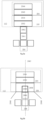
- Fig. 1 shows a schematic top view of a first substrate 102 of a microfluidic device according to some embodiments of the present disclosure.
- Fig. 2 shows a cross-sectional view of the first substrate 102 of the microfluidic device taken along the line A-B in Fig. 1 .
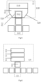
- FIG. 3a shows an arrangement schematic diagram of a plurality of drive electrodes 170 included in a reagent area and a reagent area flow channel according to some embodiments of the present disclosure.
- the first substrate 102 includes an operation area 135 and a peripheral area 105, and the peripheral area 105 may include a bonding area 115.
- the peripheral area 105 may further include a ground electrode area 1310 (see the description of Fig. 13a below).
- the first substrate 102 for the microfluidic device includes: a first base substrate 180; a first electrode layer 183 on the first base substrate, the first electrode layer including a plurality of drive electrodes 170.
- the plurality of drive electrodes 170 define at least one flow channel 128 (126), 121, 132, 142, 154, 162 and at least one functional area 112 (122), 120, 130, 140, 150, 160 in the first substrate (in particular, in the operation area 135), the at least one functional area 112 (122), 120, 130, 140, 150, 160 includes a reagent area 112 (122), the at least one flow channel 128 (126), 121, 132, 142, 154, 162 includes a reagent area flow channel 128 (126).
- the reagent area 112 includes a reagent area liquid storage portion 204 and a droplet shape changing portion 205.
- the droplet shape changing portion 205 is adjacent to the reagent area flow channel 206, and the reagent area liquid storage portion 204 is on a side of the droplet shape changing portion 205 away from the reagent area flow channel 206.
- the reagent area liquid storage portion 204, the droplet shape changing portion 205, and the reagent area flow channel 206 are configured to generate an intermediate droplet from the reagent area liquid storage portion 204 that covers the droplet shape changing portion 205 and configured to change a shape of the intermediate droplet to generate reagent droplet in the reagent area flow channel 206.
- the material of the drive electrodes 170 may be a metal, an alloy, a conductive oxide, a composite film layer, or other conductive materials.
- the drive electrodes 170 include molybdenum.
- the thickness of the first electrode layer i.e., the thickness of the drive electrodes 170
- the number of reagent areas can be two or more, to introduce different reagents into the microfluidic device respectively.
- different reagent areas can have different sizes, which can be achieved by adjusting the shape or number of electrodes that define the reagent areas.
- different reagent areas may be arranged in an array, for example, may be arranged in a three-row array, where the first row includes 9 reagent areas, and the second and third rows include 8 reagent areas respectively.
- the reagent area liquid storage portion and the droplet shape changing portion are arranged in the reagent area defined by the drive electrodes, the droplet shape changing portion is adjacent to the reagent area flow channel, and the reagent area liquid storage portion is on a side of the droplet shape changing portion away from the reagent area flow channel, which avoids the solution that the reagent area liquid storage portion is directly adjacent to the reagent area flow channel.
- the drive electrodes are arranged to form three sections corresponding to the reagent area liquid storage portion, the droplet shape changing portion, and the reagent area flow channel, respectively.
- the reagent area liquid storage portion, the droplet shape changing portion, and the reagent area flow channel are configured to generate an intermediate droplet from the reagent area liquid storage portion that covers the droplet shape changing portion and configured to change a shape of the intermediate droplet to generate a reagent droplet in the reagent area flow channel.
- an intermediate droplet shape changing portion is introduced, which can cooperate with the reagent area liquid storage portion and the reagent area flow channel to generate the intermediate droplet in the process of generating the reagent droplet and to manipulate the shape of the intermediate droplet, which ensures the consistency of the volumes of intermediate droplets before final droplets are generated, thereby ensuring the consistency of the volumes of the finally generated reagent droplets.
- the CV of 30 times of droplet generation can be controlled at about 1%, and stability and accuracy of droplet generation can be greatly improved.
- the reagent area liquid storage portion 204 may include drive electrodes 2044 and 2042 sequentially arranged along an extending direction of the reagent area flow channel 206;
- the droplet shape changing portion 205 may include drive electrodes 2054 and 2052 sequentially arranged along the extension direction of the reagent area flow channel 206 on a side of the drive electrode 2042 away from the drive electrode 2044;
- the reagent area flow channel 206 includes drive electrodes 2062, 2064 sequentially arranged along the extension direction of the reagent area flow channel 206 on a side of the drive electrode 2052 away from the drive electrode 2044.
- a sum of a projected areas of the drive electrodes 2054 and 2052 on the first base substrate 180 is smaller than a projected area of the reagent area liquid storage portion 204 on the first base substrate 180, to ensure that the consistency of the volumes of the intermediate droplets before the final droplet generation.
- the present disclosure does not limit the types of reagents, as long as the reagents can be driven by the structure proposed in the present disclosure and can achieve the purpose of the present invention, such as water, organic solution, inorganic solution, biomolecule solution, conductive liquid, electrolyte solution or ionic liquid, etc.
- flow channel refers to some areas connecting at least one functional area of the first substrate, where the fluid driven by the microfluidic device in operation may flow through these areas.
- a “flow channel” does not necessarily mean that there is a channel physically lower than other planes.
- the droplet shape changing portion 205 may include: a first electrode module 2056 including one or more electrodes, the first electrode module 2056 being arranged in a shape with a notch; and a second electrode module 2058, the second electrode module 2058 being embedded in the notch, and a sum of a projected area of the first electrode module 2056 on the first base substrate 180 and a projected area of the second electrode module 2058 on the first base substrate 180 is smaller than a projection area of the reagent area liquid storage portion 204 on the first base substrate 180, and the reagent area flow channel 206 includes a drive electrode 2066, and the second electrode module 2058 is adjacent to the drive electrode 2066 of the reagent area flow channel 206.
- an arc-shaped solitary area can be generated during the droplet generation process. Without the second electrode module 2058, the arc-shaped solitary area may cause the projected area of the reagent droplet on the first base substrate to be larger than a projected area of the drive electrode on the first base substrate when the reagent droplet is generated on the reagent area flow channel, resulting in inaccurate volume of the generated reagent droplet.
- the first electrode module 2056 is arranged in a shape with the notch, and the second electrode module 2058 is embedded in the notch to firstly generate an intermediate droplet, and the splitting and shape of the reagent droplet can be adjusted by controlling the second electrode module 2058 when the reagent droplet is generated, so that the arc-shaped solitary area exists inside the reagent area without affecting the projected area of the generated sample droplet, thereby improving the accuracy and stability of the droplet generation (referring to the description of the reagent area driving process in Figs. 14b-14i ).
- the reagent area flow channel 206 includes a central axis 2067, and the first electrode module 2056 is arranged in a symmetrical shape with respect to the central axis 2067.
- the first electrode module 2056 is arranged in a symmetrical shape with respect to the central axis 2067.
- the reagent area 112 includes a reagent area liquid storage portion 114 and a droplet shape changing portion 116.
- the droplet shape changing portion 116 is adjacent to the reagent area flow channel 128, and the reagent area liquid storage portion 114 is on a side of the droplet shape changing portion 116 away from the reagent area flow channel 128.
- the reagent area liquid storage portion 114, the droplet shape changing portion 116, and the reagent area flow channel 128 are configured to generate an intermediate droplet from the reagent area liquid storage portion 114 that covers the droplet shape changing portion 116 and configured to change a shape of the intermediate droplet to generate a reagent droplet in the reagent area flow channel 128.
- the reagent area 122 includes a reagent area liquid storage portion 124 and a droplet shape changing portion 125.
- the droplet shape changing portion 125 is adjacent to the reagent area flow channel 126, and the reagent area liquid storage portion 124 is on a side of the droplet shape changing portion 125 away from the reagent area flow channel 126.
- the reagent area liquid storage portion 124, the droplet shape changing portion 125, and the reagent area flow channel 126 are configured to generate an intermediate droplet from the reagent area liquid storage portion 124 that covers the droplet shape changing portion 125 and configured to change a shape of the intermediate droplet to generate a reagent droplet in the reagent area flow channel 126.
- the first electrode module 2056 includes a fourth electrode 240, a sixth electrode 260, and a seventh electrode 270
- the second electrode module 2058 includes a fifth electrode 250
- the reagent area liquid storage portion 114 includes a first electrode 210, a second electrode 220, and a third electrode 230 sequentially arranged along an extending direction of the reagent area flow channel 128
- the droplet shape changing portion 116 includes the fourth electrode 240 and the fifth electrode 250 sequentially arranged along the extension direction of the reagent area flow channel 128 on a side of the third electrode 230 away from the first electrode 210, and the sixth electrode 260 and the seventh electrode 270 on both sides of the fourth electrode 240 and the fifth electrode 250 perpendicular to the extension direction of the reagent area flow channel 128
- the reagent area flow channel 128 includes an eighth electrode 280 and a ninth electrode 290 sequentially arranged along the extending direction of the reagent
- the drive electrodes included in the reagent area liquid storage portion 124, the droplet shape changing portion 125, and reagent area flow channel 126 are similar to the arrangement of the drive electrodes included in the reagent area liquid storage portion 114, the droplet shape changing portion 116 and the reagent area flow channel 128, with a difference that the reagent area liquid storage portion 124 additionally includes an additional electrode 225 between the first electrode 210 and the second electrode 220.
- the liquid storage capacity of the reagent area liquid storage portion 124 is larger (for example, about 1/3 larger) than that of the reagent area liquid storage portion 114.
- the reagent area 122 can be used for the generation of 1-3 ⁇ L droplets, and the reagent area 112 can be used for the generation of 1-2 ⁇ L droplets.
- Different reagent areas can be selected according to the specific reagent dosage.
- reagent area liquid storage portion an intermediate droplet covering the droplet shape changing portion is generated, and the drive electrodes can be configured to change a shape of the intermediate droplet to form an elongated droplet covering the fourth electrode 240, the fifth electrode 250, the eighth electrode 280 and the ninth electrode 290, ensuring the consistency of the volumes of the intermediate droplets before the final reagent droplets are generated.
- the elongated droplet is split to generate reagent droplets, which ensures the consistency of volumes of the finally generated reagent droplets, which can further improve the stability and accuracy of the reagent droplet generation (referring to description of the reagent area driving process in Figs. 14j-14m ).
- the shape of the first electrode 210 may be a rectangle, two parallel sides of the rectangle of the first electrode 210 are perpendicular to the extension direction of the reagent area flow channel 128, and the rectangle is provided with chamfers at the two corners 215, 217, and the two corners 215, 217 are away from the second electrode 220 in a direction parallel to the extension direction of the reagent area flow channel 128.
- the first electrode 210 may be formed in a trapezoidal shape (an example of such a drive electrode is indicated by 210) or a shape with two sides in an arc shape (an example of such a drive electrode is indicated by 214).
- the dead volume in the droplet generation process can be reduced, and the liquid storage accuracy of the reagent area liquid storage portion can be improved.
- the "dead volume” here refers to the uncontrollable volume during the reagent injection process. Specifically, if the first electrode 210 adopts a rectangular electrode, its electric field is distributed in a rectangle. Due to the presence of the surface tension of the droplet, the position of the droplet at the edge of the rectangular electrode is not at right angles (that is, it cannot perfectly match the shape of the rectangular electrode). The shape and volume of the droplet will change, and there is certain randomness in this change of shape and volume, which introduces a dead volume.
- overall shapes of drive electrodes 2054, 2052 (or 2056, 2058) included in the droplet shape changing portion 205 are rectangles having two sides perpendicular to the extending direction of the reagent area flow channel 206.
- the rectangles are provided with chamfers at two corners 2046, 2018 on a side close to the reagent area flow channel.
- the specific manner of setting each chamfer can be similar to that of the first electrode 210, and will not be repeated here.
- the electric field formed by using the chamfered electrode here has a better matching with the actual shape of the droplet in each stage in the reagent droplet generation process (which may refer to description of the reagent area driving process in Figs. 14b-14i ).
- the electrode control accuracy can be improved, thereby improving the accuracy and stability of droplet generation.
- the shape of the first electrode 210 is an isosceles trapezoid with an upper side of 1 mm, a lower side of 3 mm, and a height of 1 mm.
- the shapes of the second electrode 220, the additional electrode 225, and the third electrode 230 are rectangles of 1mm*3mm
- the shape of the sixth electrode 260 and the seventh electrode 270 are rectangles of 1mm*2mm
- the shape of the fourth electrode 240 and the fifth electrode 250 are squares of 1mm* 1mm
- the shape of the eighth electrode 280 and the ninth electrode 290 are 1mm*1mm square electrodes.
- the spacing between the drive electrodes is 100 ⁇ m.
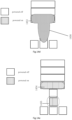
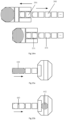
- Fig. 4 shows an arrangement schematic diagram of a plurality of drive electrodes 170 included in a waste liquid area and a waste liquid area flow channel according to some embodiments of the present disclosure.
- the at least one functional area 112 (122), 120, 130, 140, 150, 160 further includes a waste liquid area 160
- the at least one flow channel 128 (126), 121, 132, 142, 154, 162 includes a waste liquid area flow channel 162.
- the waste liquid area 160 includes a waste liquid area liquid storage portion 411 and a waste liquid area transition portion 412.
- the waste liquid area transition portion 412 is adjacent to the waste liquid area flow channel 162, and the waste liquid area liquid storage portion 411 is on a side of the waste liquid area transition portion 412 away from the waste liquid area flow channel 162.
- a drive electrode 432 included in the waste liquid area transition portion 412 is in a long strip shape, long sides of the long strip shape are perpendicular to the extending direction of the waste liquid area flow channel 162.
- a drive electrode adjacent to the waste liquid area transition portion 412 includes a notch, and the drive electrode included in the waste liquid area transition portion 412 is embedded in the notch.
- the stability and accuracy of the droplet driving can be improved.
- the reason is as follow: if the waste liquid area transition portion 412 adjacent to the waste liquid area flow channel 162 is not used, the size of the drive electrode adjacent to the waste liquid area flow channel 162 among the electrodes of the waste liquid area liquid storage portion 411 is too large, its uniform-intensity electric field has a relatively large range, and the randomness of the position of the droplet after moving to this drive electrode increases, which may affect the stability and accuracy of the droplet driving.
- the drive electrodes included in the waste liquid area 160 are provided with chamfers at positions 422, 424, 426, 428 corresponding to the corners of the waste liquid area 160.
- the specific manner of setting each chamfer can be similar to that for the first electrode 210, and will not be repeated here.
- the waste liquid can be taken out of the waste liquid area 160 with a pipette gun or a plastic dropper. Since the volume of the waste liquid in the waste area 160 can be relatively large (>30 ⁇ L) and the size of the pipette gun or plastic dropper is fixed, the use of chamfer design can reduce the dead volume in the process of droplet manipulation and prevent the occurrence of liquid extraction residues in the process of waste liquid extraction.
- the waste liquid area 160 includes an isosceles trapezoidal electrode 418 with an upper side of 4 mm, a lower side of 5 mm, and a height of 1 mm; a rectangular electrode 416 of 1 mm*5 mm; an electrode 414 including a notch with a height of 2 mm, being capable of embedding a rectangular shape of 1 mm*3 mm, a long side of 5 mm, two short sides of 0.5 mm perpendicular to the long side, and a trapezoidal transition of 1 mm; and a rectangular electrode 432 of 1 mm*3 mm.
- the spacing between the drive electrodes is 100 ⁇ m.
- the waste liquid droplets move from other areas to the waste liquid area, and finally gather in the waste liquid area liquid storage portion 411.
- the volume of the waste liquid droplet is 1-3 ⁇ L.
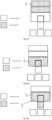
- Fig. 5 shows an arrangement schematic diagram of a plurality of drive electrodes 170 included in a sample inlet area and a sample inlet area flow channel according to some embodiments of the present disclosure.
- at least one functional area 112 (122), 120, 130, 140, 150, 160 further includes a sample inlet area 140, and at least one flow channel 128 (126), 121, 132, 142, 154, and 162 includes a sample inlet area flow channel 142.
- the sample inlet area 140 includes a sample inlet area liquid storage portion 511 and a sample inlet area transition portion 512.
- the sample inlet area transition portion 512 is adjacent to the sample inlet area flow channel 142, and the sample inlet area liquid storage portion 511 is on a side of the sample inlet area transition portion 512 away from the sample inlet area flow channel 142.
- the drive electrode adjacent to the sample inlet area transition portion 512 includes a notch, and the drive electrode 532 included in the sample inlet area transition portion 512 is embedded in the notch.
- the arc-shaped solitary area exists on the sample inlet area flow channel, which may cause the projected area of the generated sample droplet on the first base substrate to be larger than the projected area of the drive electrode on the first base substrate, making the volume of the sample droplet inaccurate.
- the drive electrode included in the sample inlet area liquid storage portion 511 adopts a design including a notch.
- the drive electrode included in the sample inlet area transition portion 512 can be controlled to adjust the splitting and shape of the droplet, so that the existence of the arc-shaped solitary area inside the sample inlet area will not affect the projected area of the generated sample droplets, thereby improving the accuracy and stability of droplet generation (referring to the description of the sample inlet area driving process in Figs 16a-16c ).
- an overall shape of the drive electrodes 532, 514, and 516 included in the sample inlet area 140 is a rectangle with two sides perpendicular to the extension direction of the sample inlet area flow channel 142, and two corners 526 and 528 of the rectangle on a side close to the sample inlet area flow channel 142 are provided with chamfers.
- the specific manner of setting each chamfer can be similar to that for the first electrode 210, and will not be repeated here.
- the electric field formed by using the chamfered electrode here has a higher match with the actual shape of the droplet in each stage of the droplet generation process in the sample inlet area (referring to the description of the sample inlet area driving process in Figs 16a-16c ), which can improve the accuracy of electrode control, thereby improving the accuracy and stability of droplet generation.
- the sample inlet area 140 includes a 1 mm*3 mm rectangular electrode 516, a notched electrode 514 (with a height of 2 mm, a long side of 3 mm, and two short sides of 0.5 mm perpendicular to the long side, and a trapezoidal transition of 1 mm) which can embed a rectangle of 1mm* 1.2 mm, and a 1 mm* 1 mm square electrode 532.
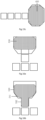
- Fig. 6 shows an arrangement schematic diagram of a plurality of drive electrodes 170 included in a sampling area and a sampling area flow channel according to some embodiments of the present disclosure.
- Fig. 7 shows an arrangement schematic diagram of a plurality of drive electrodes 170 included in a quality detection area and a quality detection area flow channel according to some embodiments of the present disclosure.
- Fig. 8a shows an arrangement schematic diagram of a plurality of drive electrodes 170 and a temperature sensor included in a temperature control area 130 according to some embodiments of the present disclosure.
- At least one functional area 112 (122), 120, 130, 140, 150, 160 further includes a sampling area 120, a quality detection area 150, and a temperature control area 130
- at least one flow channel 128 (126), 121, 132, 142, 154, 162 further includes a sampling area flow channel 121, a quality detection area flow channel 154, and a temperature control area flow channel 132.
- the sampling area 120 includes three rectangular electrodes 612, 614, and 616 of 1 mm*3 mm, and the sampling area flow channel 121 includes a square electrode 622 of 1 mm*1 mm.
- the sampling area 120 corresponds to the sampling port of the first substrate 102, and the center of a circle of the sampling port coincides with the center of the overall three 1 mm*3 mm rectangular electrodes 612, 614, and 616, so that sampling can be achieved from the sampling port through a plastic dropper or pipette.
- a diameter of the sampling port is 2 mm.
- the quality detection area 150 includes an detection area 710 (for example, an optical detection area), a flow channel 720 in the quality detection area, and a quality detection area waste liquid portion 730.
- the drive electrodes included in the quality detection area 150 may include a plurality of square electrodes with a size of 1 mm*1 mm and a plurality of rectangular electrodes with a size of 1 mm*3 mm.
- the quality detection area 150 can realize the quality detection of the samples in the microfluidic device. For example, the droplets will move from other functional areas to the quality detection area 150 through the quality detection area flow channel 154.
- the droplets move through the flow channel 720 in the quality detection area to the quality detection area waste liquid portion 730.
- the quality detection sample can be taken out of the microfluidic device through the quality detection area waste liquid portion 730.
- the temperature control area 130 may include 1 mm*1 mm square electrodes 136 (4*7 in the figure) distributed in an array.
- the temperature control area 130 may be heated to a relatively high temperature and maintained for a certain period of time, to provide conditions and places for operations such as reaction and mixing of the fluid in the microfluidic device.
- Library preparation usually refers to the following process: constructing a nucleic acid sample that requires specific sequence information into a standardized nucleic acid library that can be sequenced for sequencing through a series of biomolecular techniques such as fragment interruption, repair, connection, and amplification.
- Library preparation is an important step in the gene sequencing process. One of its purposes is to increase the concentration of nucleic acid to be detected and prepare for subsequent sequencing work.
- the library preparation technology based on the microfluidic device can greatly reduce the library preparation time, reduce the amount of reagents used, and greatly improve the level of automation. Through the microfluidic device method, the library preparation time can be reduced from 2 days in the ordinary method to about 8 hours, which greatly shortens the library preparation time.
- the process of generating and manipulating droplets can include the following process.
- Various reagents required for library preparation can be stored in each reagent area 112, 122 respectively, and when it is needed to extract the droplets of the reagent, the droplets of the reagent are generated and manipulated to move through the reagent area liquid storage portion, the droplet shape changing portion and the reagent area flow channel.
- the DNA samples whose library is needed to be constructed can be introduced into the microfluidic device from the sample inlet area 140, the amount of DNA sample used can be relatively low (for example, 1 ⁇ L), so a small volume of droplets (for example, 1 ⁇ L of droplets) needs to be generated at the sample inlet area 140.
- the temperature control area 130 provides conditions and places for the mixing and reaction, etc. of different reagents and samples.
- droplets for example, the volumes of the droplets are 1-3 ⁇ L
- the droplets (for example, the volumes of the droplets are 1-3 ⁇ L) move from the temperature control area 130 to the sampling area 120, and finally gather at the rectangular electrodes 612, 614, 616, so that sampling can be achieved from the sampling port with a plastic dropper or pipette.
- the quality detections will be performed for about 2-5 times (for example, the volume of the droplet in each quality detection is 1-3 ⁇ L), the droplet will move from other functional areas to the quality detection area 150, and moves to the quality detection area waste liquid portion 730 (from which the droplet can be taken out of the microfluidic device) after the quality detection is completed in the detection area 710.
- connection between the respective flow channels as shown in Fig. 1 may include square electrodes arranged at intervals (for example, the size is mm*1mm, and the interval is 100 ⁇ m). It should be understood that, within the scope of the present disclosure, different functional areas are not all necessary, and the positional relationship, size, and number of each functional area can be adjusted and set according to actual application requirements.
- the first substrate has a rectangular shape, and the direction parallel to the two long sides of the rectangle is the first direction.
- the first substrate 102 includes at least one column of temperature control branch 106, and each column of the at least one column of temperature control branch extends along the first direction and includes: a reagent area 112 (122), a sampling area 120, a temperature control area 130, a sample inlet area 140, and a waste liquid area 160 sequentially arranged along the first direction.
- Fig. 1 shows two temperature control branches. Such an arrangement can reduce crosscontamination between fluids, reduce the stroke of fluid movement, and improve the efficiency of detection.
- various flow channels are arranged in a network, so that at least one functional area 112 (122), 120, 130, 140, 150, and 160 of the first substrate 102 can be in communication with each other through the flow channels, which allows the fluid droplets to move between the various functional areas of the microfluidic device as required, so that various manipulations, such as reaction, mixing, liquid separation, detection, etc., can be performed.
- the quality detection area 150 is set near the middle position of the operation area 135 of the first substrate 102, so that it is convenient for the fluid in each functional area to enter the quality detection area 150 at a relatively short distance.
- At least one sampling area 112 may also be connected to the quality detection area 150 through a straight flow channel (not shown), so that the reagent in the reagent area can be directly detected without contaminating other flow channels.
- the temperature control areas 130 located in adjacent temperature control branches can also be connected by a straight flow channel (not shown), which facilitates the fluid transfer between adjacent temperature control areas at a relatively short distance, such as rapid transfer to reaction conditions of different temperatures. It should be understood that "connected by a straight flow channel” means that the drive electrodes included in the flow channel between the two functional areas are arranged in a straight line.
- the present disclosure does not limit the driving principle of the microfluidic device, as long as the structure proposed in the present disclosure can be used to drive and achieve the purpose of the present invention.
- the device that realizes microfluidic control based on drive electrodes includes various types of devices, e.g., devices based on the capillary phenomenon caused by the temperature difference, based on the wetting angle change on the medium of the double-layer substrate, based on the wetting angle change on the medium of the single-layer substrate, based on electrochemistry, etc.
- some embodiments of the present disclosure will be described by taking the driving principle based on the wetting angle change on the medium of double-layer substrate as an example.
- ⁇ 0 is the dielectric constant
- ⁇ r is the relative dielectric constant of the dielectric layer
- ⁇ 1g is the surface tension coefficient of the liquid-gas interface (when the droplet moves in the gas)
- ⁇ V is the potential difference between the two sides of the dielectric layer
- d is the thickness of the medium layer
- ⁇ 0 is the initial contact angle of the droplet when no voltage is applied to the drive electrode
- ⁇ is the contact angle of the droplet when the voltage is applied to the drive electrode.
- the first substrate 102 further includes: a first dielectric layer 184 on a side of the first electrode layer 183 away from the first base substrate 180.
- the first dielectric layer 184 may also exist in the gap between the drive electrodes 170.
- the first dielectric layer 184 may serve as the dielectric layer in the formula, thereby providing the dielectric properties required to drive the change in the contact angle of the droplet. Starting from the principle of dielectric wetting, reducing the thickness of the first dielectric layer 184 and increasing the driving voltage can enhance the dielectric wetting effect.
- the first dielectric layer 184 (especially the thickness and dielectric properties) has an important influence on the performance of the microfluidic device.
- the material of the first dielectric layer 184 when working in a normal-temperature environment, can be highly selective, such as SiNx, non-metal oxides (such as silicon oxide), organic materials (such as Resin, SU8, polyimide film), and so on.
- high temperature is one of the unavoidable environments for the application of the microfluidic device.
- the reaction temperature of part of the process in the library preparation process is 65°C and 95°C.
- the inventors of the present application find that bubbles are prone to appear on the surface of the organic layer during the preparation of the microfluidic device, and the compactness of this type of material is poor, and the material will absorb moisture in the environment after being placed for a long time, and its high-temperature resistance to breakdown is poor.
- Fig. 9 schematically shows a principle diagram of breakdown of a dielectric layer at high temperature. As shown in FIG. 9 , the droplet 190 is located on the first lyophobic layer 188 (for the relevant arrangement of the droplet and the first lyophobic layer, please refer to the description below).
- Some metal oxide layers prepared by semiconductor processes are prepared by PECVD and other processes, and there are many pinholes 910. Due to the presence of defects such as pinhole, when the microfluidic device is working at high-temperature conditions, the ion activity increases as the temperature rises, and the number of pinholes 910 in the first dielectric layer 184 (and the optional second dielectric layer, for the related settings of the second dielectric layer please refer to the description below) is increased to form a conduction channel from the liquid drop to the drive electrode, a small leakage current will be generated and the leakage current will gradually increase, thereby generating a large leakage current and thermal breakdown.
- the first dielectric layer includes aluminum oxide or polyimide.
- the relative dielectric constant of aluminum oxide or polyimide is relatively large.
- strict pre-treatment is performed before the preparation of the aluminum oxide layer to reduce the introduction of particles as much as possible, and the preparation of the aluminum oxide layer can be achieved by atomic layer deposition technology, which greatly reduces the defects of the dielectric layer This can achieve better high-temperature stability, enhance the breakdown resistance of the dielectric layer, and avoid irreversible dielectric breakdown at relatively low voltages.
- the polyimide layer can also be used to achieve stable driving of high-temperature droplets.
- the relative dielectric constant of the polyimide layer can be e.g., about 3.2, and the thickness can be e.g., 38 ⁇ m.
- the compactness of the polyimide layer can be increased by increasing the thickness of the layer, thereby preventing breakdown of the dielectric layer at high temperatures.
- the method of increasing the thickness of the dielectric layer will lead to an increase in the driving voltage of the droplets.
- the driving voltage of the droplets in the polyimide layer may be 180 Vrms.
- a microfluidic device made of such a first substrate 102 can achieve a stable drive for 3 hours at a high temperature of 95°C, and when the aluminum oxide layer is used for the first dielectric layer, its driving voltage can be controlled at 20 Vrms, that is, the driving voltage can be reduced.
- the first substrate 102 further includes: a first lyophobic layer 188 on a side of the first dielectric layer 184 away from the first base substrate 180.
- the first lyophobic layer 188 can provide good contact performance with the droplets (for example, a suitable contact angle), and increase the controllability of the droplets.
- the first lyophobic layer 188 can be made of materials such as Teflon or CYTOP.
- the contact angle of deionized water is no less than 110°, and the rolling inclination angle is less than or equal to 15°.
- the first substrate 102 further includes a temperature sensor.
- the temperature sensor is used to sense the temperature at certain positions of the first substrate, for example, to sense the temperature of certain functional areas, to facilitate the adjustment of the temperatures of the functional areas so that the functional areas meet the operating conditions of the reagent.
- the temperature sensor adopts an external solution, that is, it is arranged near the first base substrate 180.
- Fig. 8b shows a cross-sectional view of the first substrate 102, which is taken along the position shown by the line C-D in Fig. 8a .
- the first electrode layer 183 includes an opening 805 between the drive electrodes 170
- the first substrate 102 further includes a temperature sensor 810
- the temperature sensor 810 is provided in the opening 805.
- a temperature sensor 810 is provided in the opening 805 of the drive electrode 136 (in the figure shown as an example in the opening between the second row, fourth column and the fifth column of the electrodes).
- the area 812 corresponds to the drive electrode on the left side of the temperature sensor 810
- the area 814 corresponds to the temperature sensor
- the area 816 corresponds to the drive electrode on the right side of the temperature sensor 810.
- this temperature sensor 810 is located in the first electrode layer 183, and the temperature sensor 810 includes metal.
- the temperature sensor 810 has a line width of 4 ⁇ m and a resistance of 1400 ⁇ .
- one end of wiring of the temperature sensor 810 is grounded, and the other end is connected to the binding area.
- a voltage of 5V is applied, and the resistance of the temperature sensor 810 is calculated by testing the current.
- the temperature sensor 810 may be made of materials such as metal, alloy, conductive oxide, composite film layer, or other conductive materials.
- the drive electrode 170 and the temperature sensor 810 include molybdenum. In some embodiments, the drive electrode 170 and the temperature sensor 810 may be formed by the same patterning process.
- Fig. 10a schematically shows a model used for temperature simulation according to some embodiments of the present disclosure
- Figs. 10b-10c schematically show simulation diagrams of temperature distribution according to Fig. 10a
- the model 1010 indicates the first substrate 102
- the rectangular area 1020 corresponds to the temperature control area 130
- a heat source is arranged on the lower surface of the model 1010. The calculation shows that, as shown in Fig.
- the temperature at 15 mm from the center of the model 1010 (that is, the center of the rectangular area 1020) is about 25°C, which indicates that the temperature at about 1 cm from the temperature control area 130 is less affected by the temperature of the temperature control area.
- the nature of the reagent here will not be affected by the temperature of the temperature control area 130, so the distance between the temperature control area 130 and other functional areas can be set at no less than 1 cm.
- Fig. 10c shows the temperature distribution of the cross section, which is taken along the approximate y-z plane as shown in Fig. 10a .
- the heat source is arranged on the lower surface of the model 1010, so the temperature near the lower surface is the highest. It can be seen from Fig. 10c that when the first dielectric layer 184 including polyimide is used, the temperature difference between the lower surface of the first substrate 102 and the upper surface of the hydrophobic layer 188 is about 10° C, and the temperature difference between the first electrode layer 183 and the upper surface of the hydrophobic layer 188 is about 1°C.
- the temperature difference between the first electrode layer 183 and the upper surface of the hydrophobic layer 188 is about 0.01 °C. This is because the thermal conductivity of the aluminum oxide layer is 50 times that of the polyimide layer, and the thickness of the aluminum oxide layer is 1/127 of the thickness of the polyimide layer, which means that when the first dielectric layer 184 is made of aluminum oxide, the temperature measured by the temperature sensor 810 is very similar to the temperature of the lower surface of the fluid (droplet), the temperature control accuracy of the microfluidic device is greatly improved. It should be understood that due to different use environments or equipment environments, the thermal field distribution will change, and the thermal field calculation results will be different from the actual situation.
- the temperature sensor 810 when the temperature sensor 810 is fabricated in the first electrode layer 183, the temperature sensor 810 is integrated and fabricated inside the first substrate 102, which reduces the distance between the droplet and the temperature sensor 810, thereby directly reflecting the temperature of the droplet.
- Such temperature control accuracy is greatly improved compared to the temperature control accuracy when the temperature sensor is fabricated on the lower surface of the first substrate 102 (that is, the temperature sensor is externally arranged).
- the preparation of the temperature sensor 810 in the first electrode layer 183 can avoid the inability to directly and objectively feedback the droplet temperature due to the external solution of the temperature sensor, thereby significantly improving the temperature control accuracy of the microfluidic device. Therefore, the first substrate 102 provided by the embodiment of the present disclosure can significantly improve the reliability of the microfluidic device in a high-temperature environment.
- the first substrate 102 provided by the embodiments of the present disclosure may adopt different electrode designs for different functional areas, thereby improving the control accuracy of the fluid by the microfluidic device, such as fluid generation accuracy, temperature control accuracy, etc., thereby improving the performance of the microfluidic device, such as the accuracy of library preparation.
- the first substrate 102 may further include: a covering 176 on the drive electrode 170, and the covering 176 covers the surface of the drive electrode 170 except for the surface opposite to the first base substrate 180.
- the covering 176 includes ITO.
- the first substrate 102 further includes a covering 820 on the temperature sensor 810, and the covering 820 covers the surface of the temperature sensor 810 except for the surface opposite to the first base substrate 180.
- the covering 176 includes ITO.
- the thickness of the covering may be 50 nm. The covering can completely cover the drive electrode 170 and the temperature sensor 810, thereby improving the reliability of the drive electrode 170 and the temperature sensor 810, and preventing the drive electrode 170 and the temperature sensor 810 from the problem of falling off during cleaning in the preparation process.
- the first substrate 102 may further include: a second electrode layer 174 between the first base substrate 180 and the first electrode layer 183; and an insulating layer 182 between the first electrode layer 183 and the second electrode layer 174.
- the second electrode layer 174 includes a plurality of leads 175, and the drive electrode 170 in the first electrode layer 183 and the lead 175 corresponding to the drive electrode 170 are connected by a via hole 172, and the via hole 172 penetrates the insulating layer 182.
- the thickness of the second electrode layer 174 may be 220 nm.
- the material of the lead 175 may be metal, alloy, conductive oxide, composite film layer, or other conductive materials, etc.
- the lead 175 includes molybdenum.
- SiNx material can be selected for the insulating layer.
- the thickness of the insulating layer may be 600 nm.
- the driving of the drive electrode 170 may adopt various methods, such as active control, such as passive control.
- active control there may not be a thin film transistor (TFT) directly corresponding to the drive electrode 170 in the first substrate 102, and a relay in the bonding area is used to generate a driving signal for control, thereby having a relatively large cost advantage.
- TFT thin film transistor
- the first substrate 102 further includes: a second dielectric layer 186 between the first dielectric layer 184 and the first lyophobic layer 188.
- the second dielectric layer 186 can be determined according to specific requirements as to whether it needs to be provided, and the material included in the second dielectric layer 186 can be selected as required.
- the second dielectric layer 186 when the microfluidic device is used for nucleic acid extraction, can adopt an alkali-resistant parylene layer; and when the microfluidic device is used for library preparation, the second medium layer 186 can adopt a silicon oxide layer.
- reaction equation is as follows: Al 2 O 3 +2NaOH ⁇ 2NaAlO 2 +H 2 O
- a layer of second dielectric layer 186 that is resistant to alkali may be prepared on the first dielectric layer 184.
- the second dielectric layer 186 includes a parylene layer.
- the relative dielectric constant of the parylene layer may be 3.0, and the thickness may be 1 ⁇ m.
- ⁇ 1 is the relative dielectric constant of the first dielectric layer 184
- ⁇ 2 is the relative dielectric constant of the second dielectric layer 186
- di is the thickness of the first dielectric layer 184
- d 2 is the thickness of the second dielectric layer 186.
- the first lyophobic layer 188 is patterned so that the second dielectric layer 186 is periodically exposed.
- the properties of the second dielectric layer 186 can be set to achieve the modification of the surface of the first substrate 102 (at this time it is the patterned first hydrophobic layer) to achieve customized manipulation of the droplets.
- the second dielectric layer 186 includes silicon oxide, particularly a silicon oxide layer prepared by an atomic layer deposition process.
- Fig. 11a shows a schematic structural diagram of a first substrate 102 with a surface modification area according to some embodiments of the present disclosure.
- the first substrate 102 includes a plurality of drive electrodes 170, and the drive electrodes 170 are connected to the wirings 175 through the via holes 172, to realize the conduction between the drive electrodes 170 and the bonding area 115.
- the cross-sections of the via holes 172 are shown as squares, and in some embodiments, they may also have other shapes such as circles.
- the area 1110 indicates the surface modification area, which is, for example, a patterned first hydrophobic layer, and the specific structure of the patterned first hydrophobic layer is shown in Fig. 11b .
- the first hydrophobic layer 188 can be patterned in the detection area 710 so that the second dielectric layer 186 is periodically exposed.
- the exposed size of the second dielectric layer 186 is, for example, 4 ⁇ m*4 ⁇ m square for chemical modification or DNA capture and release.
- the thickness of the second dielectric layer 186 including the silicon oxide layer is 300 nm.
- the silicon oxide layer is made by the following principle: the precursor including (C 2 H 5 ) 4 SiN 2 H 2 and O 3 , and the reaction equation being 2(C 2 H 5 ) 4 SiN 2 H 2 +2O 3 ⁇ 2SiO 2 +O 2 +4HN(C 2 H 5 ) 2 .
- the first substrate 102 provided by the embodiments of the present disclosure can adopt different film layer designs for different functional areas, thereby improving the control accuracy of the fluid by the microfluidic device, such as fluid generation accuracy, temperature control accuracy, etc., thereby improving the performance of the microfluidic device, such as the accuracy of library preparation.
- the first base substrate may be a PCB base substrate, and the surface roughness of the PCB base substrate is relatively large, generally about 0.5 ⁇ m, which may lead to a relatively large surface resistance, thereby limiting the movement speed of the droplets.
- the stable driving speed of the PCB base substrate may be about 0.5 mm/s.
- the first base substrate 180 may include glass. The roughness of the glass base substrate (approximately 0.01 ⁇ m) is about 1/50 of that of the PCB base substrate, and the steady driving speed of the droplets of the glass base substrate can reach about 10 mm/s.
- the embodiments of the present disclosure also provide a microfluidic device.
- Fig. 12 shows a cross-sectional view of a microfluidic device according to some embodiments of the present disclosure, the cross-sectional view being taken along the same cross-section as Fig. 2 .
- the microfluidic device 1200 includes a first substrate 102 according to any one of the first substrates as described above, and a second substrate 1210 assembled with the first substrate 102.
- the second substrate 1210 includes: a second base substrate 196; a conductive layer 194 on the second base substrate; and a second lyophobic layer 192 on the side of the conductive layer away from the second base substrate.
- a space 1220 is defined between the first substrate 102 and the second substrate 1210.
- the droplet 190 may be driven by the drive electrode 170 to move in the space 1220.
- the space 1220 may be filled with air.
- the space 1220 may be filled with silicone oil or the like without contaminating the droplets, and the silicone oil may be used as a lubricant.
- the conductive layer 194 of the second substrate 1210 can be made of ITO or PEDOT material.
- the sheet resistance of the conductive layer 194 is less than 200 ⁇ /Squ.
- the second lyophobic layer 192 may include the same material as the first lyophobic layer 188.
- Fig. 13a schematically shows the surface of the first substrate opposite to the second substrate of the microfluidic device 1300 according to some embodiments of the present disclosure.
- Fig. 13b schematically shows a cross-sectional view of a microfluidic device according to some embodiments of the present disclosure, which is taken along the position shown by the line E-F in Fig. 13a .
- the first substrate 102 includes a peripheral area 1305 and an operation area 1335.
- the peripheral area 1305 may include a ground electrode area 1310.
- the ground electrode area 1310 has a ring shape.
- the ground electrode area 1310 is provided with a ground electrode 1350, and the conductive layer 194 of the second substrate 1210 is electrically connected to the ground electrode 1350. In this way, the conductive layer 194 of the second substrate 1210 can be grounded, so that the drive electrode 170 can drive the droplet 190.
- the second substrate is grounded through the peripheral ground electrode of the first substrate, which improves the grounding stability of the second substrate.
- the conductive layer 194 is electrically connected to the ground electrode 1350 through the conductive cotton 1340 to realize the grounding function of the second substrate 1210.
- the ground electrode 1350 is covered with a covering 1352, and the covering 1352 is located between the ground electrode 1350 and the conductive cotton 1340.
- the covering 1352 includes ITO.
- the area 1320 is a two-dimensional code preparation area, which includes a mark 1322 (for example, a two-dimensional code).
- the production information of the microfluidic device can be tracked through the preparation of the two-dimensional code. Since lasers are required for the production of the two-dimensional code, this area is not covered by the covering 1352.
- the area 1330 includes alignment marks 1360 for making the first lyophobic layer 188, the first dielectric layer 184, and the second dielectric layer 186.
- the first lyophobic layer 188, the first dielectric layer 184, and the second dielectric layer 186 cover the middle area of the four cross-shaped alignment marks 1360, so that they can be well aligned.
- the preparation accuracy of the first lyophobic layer 188, the first dielectric layer 184, and the second dielectric layer 186 can be improved.
- one or more of the first lyophobic layer 188, the first dielectric layer 184, the second dielectric layer 186, and the insulating layer 182 are kept clear of the cutting width during the cutting of the first base substrate 180.
- the end surface of the insulating layer 182 is no less than 150 ⁇ m away from the end surface of the first base substrate 180. That is, in the peripheral area 1305, the distance between the projection of the insulating layer 182 on the first base substrate 180 and the cutting surface 1801 of the first base substrate 180 is no less than 150 ⁇ m.
- microfluidic device has similar characteristics and technical effects to the above-mentioned microfluidic substrate, and will not be repeated here.
- the embodiments of the present disclosure also provide a driving method for a microfluidic device.
- the microfluidic device 1200 includes a first substrate 102 according to any one of the first substrates as described above, and a second substrate 1210 assembled with the first substrate 102.
- the second substrate 1210 includes: a second base substrate 196; a conductive layer 194 on the second base substrate; and a second lyophobic layer 192 on the side of the conductive layer 194 away from the second base substrate 196.
- a space 1220 is defined between the first substrate 102 and the second substrate 1210.
- Fig. 14a schematically shows a flowchart of a driving method 1400 according to some embodiments of the present disclosure.
- Figs. 14b-14m schematically show a driving process for the reagent area 112 according to some embodiments of the present disclosure.
- the driving method 1400 may include steps S1410-S1440.
- the driving process may include the following steps:
- the specific arrangement of the electrodes in the reagent area 112 may be the same as or similar to that shown in Fig. 3b .
- the step S1430 may include: powering on the first electrode module 2056, the second electrode module 2058, and the drive electrode 2066 of the reagent area flow channel 206 to change the shape of the intermediate droplet.
- the step S1440 may include: powering off the second electrode module 2058 to generate the reagent droplet in the reagent area flow channel 206.
- the driving process may include the following steps:
- the sample injection of the reagent area and the generation of reagent droplets can be realized.
- This driving method has advantages and effects similar to those described above with respect to Fig. 3b , and will not be repeated here.
- the shape of the intermediate droplet 1452 changes, and the changed droplet is 1453.
- an elongated stretched part will be produced.
- the projected area of the reagent droplet 1455 on the first base substrate may be larger than the projected area of the drive electrode 2064 on the first base substrate when the reagent droplet 1455 is being generated on the reagent area flow channel 206, resulting in the volume of the generated reagent droplet 1455 is not accurate.
- the arc-shaped solitary area 1466 exists inside the reagent area 112, so as not to affect the projected area of the generated reagent droplet 1465 on the first base substrate, thereby improving the accuracy and stability of droplet generation.
- an overall shape of the drive electrodes 2054, 2052 (or 2056, 2058) included in the droplet shape changing portion 205 is a rectangle with two sides perpendicular to an extending direction of the reagent area channel 206.
- the two corners 2046 and 2018 of the rectangle on a side close to the reagent area flow channel may be provided with chamfers.
- the specific manner of setting each chamfer can be similar to that for the first electrode 210, and will not be repeated here.
- the electric field formed by using the chamfered electrode here has a better matching with the actual shape of the droplets 1462, 1463, 1464 in each stage in the reagent droplet generation process, which can improve the accuracy of electrode control, thereby improving the accuracy and stability of droplet generation.
- the specific arrangement of the electrodes in the reagent area 112 and the reagent area 122 may be the same as or similar to that shown in Fig. 3c .
- the step S1410 may include: powering on the first electrode 210, the second electrode 220, and the third electrode 230 to perform the reagent sample injection of the reagent area liquid storage portion 114 (as shown by 312 in Fig. 14j , and as shown by 314 in Fig. 14j for the reagent area 122 in Fig. 3c ).
- the step S1420 may include: powering off the first electrode 210, the second electrode 220, and the third electrode 230 and powering on the fourth electrode 240, the sixth electrode 260, and the seventh reagent area 270 electrode; powering on the second electrode 220 and the third electrode 230; powering off the third electrode 230, and simultaneously powering on the fifth electrode 250, the sixth electrode 260, the seventh electrode 270, the first electrode 210, and the second electrode 220 to generate a droplet from the reagent area liquid storage portion 114 that covers the fourth electrode 240, the fifth electrode 250, the sixth electrode 260, and the seventh electrode 270 (as shown by 324 in Fig. 14k , and as shown by 334 in Fig.
- the step S1430 may include: powering off the sixth electrode 260 and the seventh electrode 270 and powering on the eighth electrode 280; and powering on the ninth electrode 290 to change the shape of the intermediate droplet (as shown by 344 in Fig. 14l , and as shown by 354 in Fig. 14l for the reagent area 122 in Fig. 3c ).
- the step S1440 may include: powering off the fifth reagent area 250 electrode to generate the reagent droplet in the reagent area flow channel 126 (as shown by 364 and 366 in Fig. 14m ; and as shown by 374 and 376 in Fig.
- the on-off state (power-on and power-off steps) of the additional electrode 225 may be consistent with that of the first electrode 210.
- the driving method for the waste liquid area may include: driving the droplet 430 from other functional areas (such as the temperature control area 130) to the waste liquid area 160 (as shown in Fig. 15a ); controlling the drive electrodes included in the waste liquid area transition portion 412 to move the droplet to the middle position of the waste liquid area liquid storage portion 411 (indicated by 442), while there may be other droplets 440 driven to the waste liquid area 160 (as shown in Fig. 15b ); and finally gathering a plurality of droplets 450 to the waste liquid area liquid storage portion 411.
- This driving method has advantages and effects similar to those described above with reference to the waste liquid area 160 of the first substrate 102, and will not be repeated here.
- the driving method for the sample inlet area may include: injecting a large droplet 530 into the sample inlet area (as shown in Fig. 16a ); controlling the drive electrodes included in the sample inlet area transition portion 512 so that the intermediate droplet 540 generates an elongated stretched part 542 (as shown in Fig.
- the arc-shaped solitary area 541 exists inside the sample inlet area, so as not to affect the projected area of the generated sample droplets on the first base substrate); and controlling the drive electrodes included in the sample inlet area transition portion 512 (for example, powering off the 1mm*1mm square electrode 532) to realize the splitting of large droplets and complete the generation of small droplets (such as sample droplets) 552 (as shown in Fig. 16c , where the remaining part of the intermediate droplet 530 is labeled as 550.
- the electric field formed by using the chamfered electrode here has a better matching with the actual shape of the droplet 540, 550 in each stage in the droplet generation process in the sample inlet area).
- the droplet with a small volume for example, 1 ⁇ L
- This driving method has advantages and effects similar to those described above with reference to the sample inlet area 140 of the first substrate 102, and will not be repeated here.
- the driving method for the sampling area may include: driving the droplet 630 from other functional areas (such as the temperature control area 130) to the sampling area 120 (as shown by the arrow in Fig. 17a ); controlling the drive electrodes included in the sampling area 120 and the sampling area flow channel 121 to move the droplet 630 to the sampling area flow channel 121, while there may be other droplets 640 driven to the sampling area 120 (as shown in Fig.
- the driving method for the quality detection area 150 may include: driving the droplet 740 from other functional areas to the quality detection area 150 (as shown in Fig. 18a ); completing the detection in the detection area (for example, the optical detection area) 710 (as shown in Fig. 18b ); after the detection is completed, driving the droplet 740 to the quality detection area waste liquid portion 730 (as shown in Fig. 18c ).
- the waste liquid can be taken out of the microfluidic device from the quality detection area waste liquid portion 730.
- the embodiments of the present disclosure also provide a method of manufacturing a first substrate for a microfluidic device.
- Fig. 19 schematically shows a flowchart of a method 1900 for manufacturing a first substrate for a microfluidic device according to some embodiments of the present disclosure. As shown in Fig.
- the method 1900 includes S1910 preparing a first base substrate; and S1920 preparing a first electrode layer on the base substrate, the first electrode layer including a plurality of drive electrodes, wherein the plurality of drive electrodes define at least one flow channel and at least one functional area in the first substrate, the at least one functional area includes a reagent area, the at least one flow channel includes a reagent area flow channel, the reagent area includes a reagent area liquid storage portion and a droplet shape changing portion, the droplet shape changing portion is adjacent to the reagent area flow channel, and the reagent area liquid storage portion is on a side of the droplet shape changing portion away from the reagent area flow channel, and wherein the reagent area liquid storage portion, the droplet shape changing portion, and the reagent area flow channel are configured to generate an intermediate droplet from the reagent area liquid storage portion that covers the droplet shape changing portion and configured to change the shape of the intermediate droplet to generate a reagent droplet in the reagent area flow
- the first substrate further includes: a second electrode layer between the first base substrate and the first electrode layer; and an insulating layer between the first electrode layer and the second electrode layer, the second electrode layer includes a plurality of leads, a drive electrode in the first electrode layer and a lead corresponding to the drive electrode are connected by a via hole, and the via hole penetrates the insulating layer.
- the method of manufacturing a first substrate for a microfluidic device may include: firstly preparing a second electrode layer 174 on the first base substrate optionally using a semiconductor process, and then fabricating an insulating layer 182, the first electrode layer 183, and an optional covering 176 on the second electrode layer 174, to form an intermediate product.
- the formed intermediate product may be washed.
- the method of manufacturing a first substrate for a microfluidic device may further include: preparing the first dielectric layer by atomic layer deposition.
- the first dielectric layer 184 of polyimide is prepared by a high-temperature static pressure process or the first dielectric layer 184 is prepared by an atomic layer deposition process (such as an aluminum oxide layer, for the embodiments of specific process please refer to the description of Figs. 20-22 below).
- the first substrate may further include: a second dielectric layer between the first dielectric layer and the first lyophobic layer.
- the second dielectric layer 186 may be fabricated by an atomic layer deposition technique or a PECVD process.
- the first substrate may further include: a first lyophobic layer on a side of the first dielectric layer away from the first base substrate.
- a first lyophobic layer on a side of the first dielectric layer away from the first base substrate.
- the first hydrophobic layer 188 is fabricated to form the first substrate.
- the microfluidic device includes a second substrate assembled with the first substrate, and the second substrate includes: a second base substrate; a conductive layer on the second base substrate; and a second lyophobic layer on a side of the conductive layer away from the second base substrate, where a space is defined between the first substrate and the second substrate.
- a conductive layer and a second hydrophobic layer are fabricated on the second base substrate to form the second substrate. The formed first substrate and the formed second substrate are assembled to form a microfluidic device.
- the formed intermediate product may be cut, and a blue film may be prepared through a screen printing process to protect the intermediate product and reduce the introduction of particles before the preparation of the next film layer.
- Fig. 20 shows a flow chart of the pretreatment process of preparing an aluminum oxide layer by atomic layer deposition and the corresponding component surface according to some embodiments of the present disclosure.
- the protective blue film on the surface of the component i.e., the intermediate product formed by the previous process
- the component is left to stand for 2 days to remove static electricity.
- the surface of the component is observed under a dark field microscope to detect the size and quantity of particles (for example, at this time the surface of the component is shown in the first picture on the right in Fig. 20 ).
- the components are ultrasonically washed, and the surface of the components is observed under a dark-field microscope to detect the size and quantity of particles (for example, at this time the surface of the component is shown in the second picture on the right in Fig. 20 ).
- perform plasma washing on the components for example, using Ar gas
- observe the surface of the components under a dark-field microscope to detect the size and quantity of particles for example, at this time the surface of the components is shown in the third picture on the right in Fig. 20 ).
- Wiring 2010, via holes 2020, and presence or absence of particles, etc. can be seen on the surface of the components.
- the first dielectric layer 184 (aluminum oxide) is prepared using atomic layer deposition technology, the precursors of which are Al(CH 3 ) 3 and O 2 , and the reaction principle is: 2Al(CH 3 ) 3 +6O 2 ⁇ Al 2 O 3 +9H 2 O
- Fig. 21 schematically shows a flow chart of a film formation process of an aluminum oxide layer and a corresponding principle diagram according to some embodiments of the present disclosure.
- the surface of the component is bombarded with plasma to achieve the hydroxylation of the substrate, and then the precursor A Al(CH 3 ) 3 is introduced to make the Al atoms adsorb on the surface of the substrate and release the by-product (CH 4 ), and then the protective gas (N 2 ) is introduced to wash the chamber to ensure that the excess precursor A and by-products are discharged from the chamber.
- Fig. 22 shows the surface of the component after the aluminum oxide layer is prepared by atomic layer deposition according to some embodiments of the present disclosure. After completing the preparation of this layer, the surface of the component is observed under a dark-field microscope to detect the size and quantity of particles.
- the preparation method of the aluminum oxide layer realized by the atomic layer deposition technology has advantages and effects similar to those described above with respect to the first substrate 102, which will not be repeated here.
- the microfluidic device made by such a first substrate 102 can drive 17 kinds of library construction reagents and 9 kinds of conventional reagents without dielectric layer breakdown at 95°C with the driving voltage of 20 Vrms.
- the driving voltage of some alcohol reagents such as methanol, ethanol, isopropanol, etc. can be reduced to no more than 10 Vrms.
Landscapes
- Chemical & Material Sciences (AREA)
- Health & Medical Sciences (AREA)
- Life Sciences & Earth Sciences (AREA)
- Analytical Chemistry (AREA)
- General Health & Medical Sciences (AREA)
- Engineering & Computer Science (AREA)
- Bioinformatics & Cheminformatics (AREA)
- Clinical Laboratory Science (AREA)
- Chemical Kinetics & Catalysis (AREA)
- Dispersion Chemistry (AREA)
- Wood Science & Technology (AREA)
- Biotechnology (AREA)
- Organic Chemistry (AREA)
- Zoology (AREA)
- Biochemistry (AREA)
- Hematology (AREA)
- General Engineering & Computer Science (AREA)
- Medicinal Chemistry (AREA)
- Biomedical Technology (AREA)
- Microbiology (AREA)
- Sustainable Development (AREA)
- Genetics & Genomics (AREA)
- Physics & Mathematics (AREA)
- Pathology (AREA)
- General Physics & Mathematics (AREA)
- Immunology (AREA)
- Physical Or Chemical Processes And Apparatus (AREA)
- Automatic Analysis And Handling Materials Therefor (AREA)
Claims (14)
- Erstes Substrat (102) für eine mikrofluidische Vorrichtung, umfassend:ein erstes Basissubstrat (180);eine erste Elektrodenschicht (183) auf dem ersten Basissubstrat (180), die erste Elektrodenschicht (183) umfassend eine Vielzahl von Antriebselektroden (170);eine erste dielektrische Schicht (184) auf einer Seite der ersten Elektrodenschicht (183) weg von dem ersten Basissubstrat (180);eine erste lyophobe Schicht (188) auf einer Seite der ersten dielektrischen Schicht (184) weg von dem ersten Basissubstrat (180);eine zweite Elektrodenschicht (174) zwischen dem ersten Basissubstrat (180) und der ersten Elektrodenschicht (183);eine Isolierschicht (182) zwischen der ersten Elektrodenschicht (183) und der zweiten Elektrodenschicht (174); undeine zweite dielektrische Schicht (186) zwischen der ersten dielektrischen Schicht (184) und der ersten lyophoben Schicht (188),wobei die Vielzahl von Antriebselektroden (170) mindestens einen Strömungskanal (128, 126, 121, 132, 142, 154, 162) und mindestens einen Funktionsbereich (112, 122, 120, 130, 140, 150, 160) in dem ersten Substrat (102) definiert, der mindestens eine Funktionsbereich (112, 122, 120, 130, 140, 150, 160) einen Reagenzbereich umfasst, der mindestens eine Strömungskanal (128, 126, 121, 132, 142, 154, 162) einen Reagenzbereichströmungskanal umfasst, der Reagenzbereich einen Reagenzbereichflüssigkeitsspeicherabschnitt (204, 114) und einen Tropfenformänderungsabschnitt (205, 116) umfasst, sich der Tropfenformänderungsabschnitt (205, 116) angrenzend an den Reagenzbereichströmungskanal (206, 128) befindet, und sich der Reagenzbereichflüssigkeitsspeicherabschnitt (204, 114) auf einer Seite des Tropfenformänderungsabschnitts (205, 116) weg von dem Reagenzbereichströmungskanal (206, 128) befindet,wobei der Reagenzbereichflüssigkeitsspeicherabschnitt (204, 114), der Tropfenformänderungsabschnitt (205, 116) und der Reagenzbereichströmungskanal (206, 128) konfiguriert sind, um einen Zwischentropfen aus dem Reagenzbereichflüssigkeitsspeicherabschnitt (204, 114) zu erzeugen, der den Tropfenformänderungsabschnitt (205, 116) bedeckt, und konfiguriert sind, um eine Form des Zwischentropfens zu ändern, um einen Reagenztropfen in dem Reagenzbereichströmungskanal (206, 128) zu erzeugen,wobei die zweite Elektrodenschicht (174) eine Vielzahl von Leitungen (175) umfasst, eine Antriebselektrode (170) in der ersten Elektrodenschicht (183) und eine Leitung (175), die der Antriebselektrode (170) entspricht, durch ein Durchgangsloch (172) verbunden sind und das Durchgangsloch (172) die Isolierschicht (182) durchdringt, undwobei in einem oder mehreren Funktionsbereichen des mindestens einen Funktionsbereichs (112, 122, 120, 130, 140, 150, 160) die erste lyophobe Schicht (188) gemustert ist, so dass die zweite dielektrische Schicht (186) periodisch freigelegt wird.
- Erstes Substrat (102) nach Anspruch 1, wobei der Tropfenformänderungsabschnitt (205) umfasst:ein erstes Elektrodenmodul (2056), umfassend eine oder mehrere Elektroden, wobei das erste Elektrodenmodul (2056) in einer Form mit einer Kerbe angeordnet ist; undein zweites Elektrodenmodul (2058), wobei das zweite Elektrodenmodul (2058) in der Kerbe eingebettet ist, undwobei eine Summe eines projizierten Bereichs des ersten Elektrodenmoduls (2056) auf dem ersten Basissubstrat (180) und einem projizierten Bereich des zweiten Elektrodenmoduls (2058) auf dem ersten Basissubstrat (180) kleiner als ein projizierter Bereich desReagenzbereichflüssigkeitsspeicherabschnitts (204) auf dem ersten Basissubstrat (180) ist, und
der Reagenzbereichströmungskanal (206) eine Antriebselektrode (2066) umfasst, und das zweite Elektrodenmodul (2058) an die Antriebselektrode (2066) des Reagenzbereichströmungskanals (206) angrenzt. - Erstes Substrat (102) nach Anspruch 2,wobei der Reagenzbereichströmungskanal (206) eine Mittelachse (2067) umfasst und das erste Elektrodenmodul (2056) in einer symmetrischen Form hinsichtlich der Mittelachse (2067) angeordnet ist; undwobei eine Gesamtform einer Antriebselektrode (2054, 2052, 2056, 2058), die in dem Tropfenformänderungsabschnitt (205) enthalten ist, ein Rechteck mit zwei Seiten ist, die senkrecht zu einer Erstreckungsrichtung des Reagenzbereichströmungskanals (206) verlaufen,und zwei Ecken (2046, 2018) des Rechtecks auf einer Seite nahe dem Reagenzbereichströmungskanal (206) mit Fasen versehen sind.
- Erstes Substrat (102) nach Anspruch 2 oder 3, wobei das erste Elektrodenmodul (2056) eine vierte Elektrode (240), eine sechste Elektrode (260) und eine siebte Elektrode (270) umfasst und das zweite Elektrodenmodul (2058) eine fünfte Elektrode (250) umfasst,der Reagenzbereichflüssigkeitsspeicherabschnitt (114) eine erste Elektrode (210), eine zweite Elektrode (220) und eine dritte Elektrode (230) umfasst, die entlang einer Erstreckungsrichtung des Reagenzbereichströmungskanals (128) sequentiell angeordnet sind;der Tropfenformänderungsabschnitt (116) die vierte Elektrode (240) und die fünfte Elektrode (250), die entlang der Erstreckungsrichtung des Reagenzbereichströmungskanals (128) auf einer Seite der dritten Elektrode (230) weg von der ersten Elektrode (210), und die sechste Elektrode (260) und die siebte Elektrode (270) auf beiden Seiten der vierten Elektrode (240) und der fünften Elektrode (250) umfasst, die senkrecht zu der Erstreckungsrichtung des Reagenzbereichströmungskanals (128) sequentiell angeordnet sind; undder Reagenzbereichströmungskanal (128) eine achte Elektrode (280) und eine neunte Elektrode (290) umfasst, die entlang der Erstreckungsrichtung des Reagenzbereichströmungskanals (128) auf einer Seite der fünften Elektrode (250) weg von der ersten Elektrode (210) sequentiell angeordnet sind;wobei die erste Elektrode (210) ein Rechteck ist, zwei parallele Seiten des Rechtecks senkrecht zu der Erstreckungsrichtung des Reagenzbereichströmungskanals (128) verlaufen, und das Rechteck an zwei Ecken (215, 217) mit Fasen versehen ist, und die zwei Ecken (215, 217) in einer Richtung parallel zu der Erstreckungsrichtung des Reagenzbereichströmungskanals (128) von der zweiten Elektrode (220) weg verlaufen.
- Erstes Substrat (102) nach einem der Ansprüche 1 bis 4, wobei der mindestens eine Funktionsbereich (112, 122, 120, 130, 140, 150, 160) ferner einen Abfallflüssigkeitsbereich (160) umfasst und der mindestens eine Strömungskanal (128, 126, 121, 132, 142, 154, 162) ferner einen Abfallflüssigkeitsbereichströmungskanal (162) umfasst,der Abfallflüssigkeitsbereich (160) einen Abfallflüssigkeitsbereichflüssigkeitsspeicherabschnitt (411) und einen Abfallflüssigkeitsbereichübergangsabschnitt (412) umfasst, wobei sich der Abfallflüssigkeitsbereichübergangsabschnitt (412) angrenzend an den Abfallflüssigkeitsbereichströmungskanal (162) befindet und sich der Abfallflüssigkeitsbereichflüssigkeitsspeicherabschnitt (411) auf einer Seite des Abfallflüssigkeitsbereichübergangsabschnitts (412) weg von dem Abfallflüssigkeitsbereichströmungskanal (162) befindet, eine Antriebselektrode (432), die in dem Abfallflüssigkeitsbereichübergangsabschnitt (412) enthalten ist, eine lange Streifenform vorweist, lange Seiten der langen Streifenform senkrecht zu der Erstreckungsrichtung des Abfallflüssigkeitsbereichströmungskanals (162) verlaufen, unter den Antriebselektroden (414, 416, 418), die in dem Abfallflüssigkeitsbereichflüssigkeitsspeicherabschnitt (411) enthalten sind, eine Antriebselektrode angrenzend an den Abfallflüssigkeitsbereichübergangsabschnitt (412) eine Kerbe umfasst, und die Antriebselektrode, die in dem Abfallflüssigkeitsbereichübergangsabschnitt (412) enthalten ist, in die Kerbe eingebettet ist;wobei die Antriebselektroden, die in dem Abfallflüssigkeitsbereich (160) enthalten sind, an Positionen (422, 424, 426, 428) mit Fasen versehen sind, die den Ecken des Abfallflüssigkeitsbereichs (160) entsprechen.
- Erstes Substrat (102) nach einem der Ansprüche 1 bis 5, wobei der mindestens eine Funktionsbereich (112, 122, 120, 130, 140, 150, 160) ferner einen Probeneinlassbereich (140) umfasst und der mindestens eine Strömungskanal (128, 126, 121, 132, 142, 154, 162) ferner einen Probeneinlassbereichströmungskanal (142) umfasst,der Probeneinlassbereich (140) einen Probeneinlassbereichflüssigkeitsspeicherabschnitt (511) und einen Probeneinlassbereichübergangsabschnitt (512) umfasst, wobei sich der Probeneinlassbereichübergangsabschnitt (512) angrenzend an den Probeneinlassbereichströmungskanal (142) befindet und sich der Probeneinlassbereichflüssigkeitsspeicherabschnitt (511) auf einer Seite des Probeneinlassbereichübergangsabschnitts (512) weg von dem Probeneinlassbereichströmungskanal (142) befindet, unter den Antriebselektroden (514, 516), die in dem Probeneinlassbereichflüssigkeitsspeicherabschnitt (511) enthalten sind, eine Antriebselektrode angrenzend an den Probeneinlassbereichübergangsabschnitt (512) eine Kerbe umfasst, und eine Antriebselektrode (532), die in dem Probeneinlassbereichübergangsabschnitt (512) enthalten ist, in die Kerbe eingebettet ist;wobei eine Gesamtform einer Antriebselektrode (532, 514, 516), die in dem Probeneinlassbereich (140) enthalten ist, ein Rechteck mit zwei Seiten ist, die senkrecht zu einer Erstreckungsrichtung des Probeneinlassbereichströmungskanals (142) verlaufen, und zwei Ecken (526, 528) des Rechtecks auf einer Seite nahe dem Probeneinlassbereichströmungskanal (142) mit Fasen versehen sind.
- Erstes Substrat (102) nach einem der Ansprüche 1 bis 6,wobei der mindestens eine Funktionsbereich (112, 122, 120, 130, 140, 150, 160) ferner einen Temperatursteuerbereich (130), einen Probenahmebereich (120) und einen Qualitätserkennungsbereich (150) umfasst, und der mindestens eine Strömungskanal (128, 126, 121, 132, 142, 154, 162) ferner einen Temperatursteuerbereichströmungskanal (132), einen Probenahmebereichströmungskanal (121) und einen Qualitätserkennungsbereichströmungskanal (154) umfasst, undwobei das erste Substrat (102) eine rechteckige Form aufweist, eine Richtung parallel zu zwei langen Seiten des Rechtecks eine erste Richtung ist und das erste Substrat (102) mindestens eine Spalte eines Temperatursteuerzweigs (106) umfasst, wobei jede Spalte der mindestens einen Spalte eines Temperatursteuerzweigs (106) sich entlang der ersten Richtung erstreckt und umfasst:
der Reagenzbereich (112, 122), der Probenentnahmebereich (120), der Temperatursteuerbereich (130), der Probeneinlassbereich (140) und der Abfallflüssigkeitsbereich (160), die entlang der ersten Richtung sequentiell angeordnet sind. - Erstes Substrat (102) nach Anspruch 7, wobei der Temperatursteuerbereich (130) eine Öffnung (805) in der ersten Elektrodenschicht (183) und zwischen den Antriebselektroden (170) umfasst, der Temperatursteuerbereich (130) ferner einen Temperatursensor (810) umfasst und der Temperatursensor (810) in der Öffnung (805) bereitgestellt ist.
- Erstes Substrat (102) nach Anspruch 8, ferner umfassend:Abdeckungen (176) auf den Antriebselektroden (170), wobei die Abdeckungen (176) Oberflächen der Antriebselektroden (170) mit Ausnahme einer Oberfläche bedecken, die dem ersten Basissubstrat (180) gegenüberliegt, und die Abdeckungen (176) ITO umfassen; odereine Abdeckung (176) auf dem Temperatursensor (810), wobei die Abdeckung (176) Oberflächen des Temperatursensors (810) mit Ausnahme einer Oberfläche abdeckt, die dem ersten Basissubstrat (180) gegenüberliegt, und die Abdeckung (176) ITO umfasst.
- Mikrofluidische Vorrichtung (1200), umfassend das erste Substrat (102) nach einem der vorstehenden Ansprüche und ein zweites Substrat (1210), das mit dem ersten Substrat (102) zusammengebaut wird, das zweite Substrat (1210) umfassend:ein zweites Basissubstrat (196);eine leitfähige Schicht (194) auf dem zweiten Basissubstrat (196); undeine zweite lyophobe Schicht (192) auf einer Seite der leitfähigen Schicht (194) weg von dem zweiten Basissubstrat (196),wobei ein Raum (1220) zwischen dem ersten Substrat (102) und dem zweiten Substrat (1210) definiert ist, eine Erdungselektrode (1350) auf einem Umfang des ersten Substrats (102) bereitgestellt ist und die leitfähige Schicht (194) des zweiten Substrats (1210) mit der Erdungselektrode (1350) elektrisch verbunden ist.
- Antriebsverfahren (1400) für eine mikrofluidische Vorrichtung (1200), die mikrofluidische Vorrichtung (1200) umfassend das erste Substrat (102) nach einem der Ansprüche 1 bis 9 und ein zweites Substrat (1210), das mit dem ersten Substrat (102) zusammengebaut wird, wobei das zweite Substrat (1210) umfasst:ein zweites Basissubstrat (196);eine leitfähige Schicht (194) auf dem zweiten Basissubstrat (196); undeine zweite lyophobe Schicht (192) auf einer Seite der leitfähigen Schicht (194) weg von dem zweiten Basissubstrat (196),wobei ein Raum (1220) zwischen dem ersten Substrat (102) und dem zweiten Substrat (1210) definiert ist,das Antriebsverfahren (1400) umfassend:Steuern des Reagenzbereichflüssigkeitsspeicherabschnitts (204, 114), um eine Probeninjektion des Reagenzbereichflüssigkeitsspeicherabschnitts (204, 114) durchzuführen;Steuern des Reagenzbereichflüssigkeitsspeicherabschnitts (204, 114) und des Tropfenformänderungsabschnitts (205, 116), um einen Zwischentropfen aus dem Reagenzbereichflüssigkeitsspeicherabschnitt (204, 114) zu erzeugen, der den Tropfenformänderungsabschnitt (205, 116) bedeckt;Steuern des Tropfenformänderungsabschnitts (205, 116) und des Reagenzbereichströmungskanals (206, 128), um die Form des Zwischentropfens zu ändern; undSteuern des Tropfenformänderungsabschnitts (205, 116) oder des Reagenzbereichströmungskanals (206, 128), um einen Reagenztropfen in dem Reagenzbereichströmungskanal (206, 128) zu erzeugen.
- Antriebsverfahren (1400) nach Anspruch 11, wobei der Tropfenformänderungsabschnitt (205) umfasst:ein erstes Elektrodenmodul (2056), umfassend eine oder mehrere Elektroden, wobei das erste Elektrodenmodul (2056) in einer Form mit einer Kerbe angeordnet ist; undein zweites Elektrodenmodul (2058), wobei das zweite Elektrodenmodul (2058) in der Kerbe eingebettet ist, undwobei eine Summe eines projizierten Bereichs des ersten Elektrodenmoduls (2056) auf dem ersten Basissubstrat (180) und einem projizierten Bereich des zweiten Elektrodenmoduls (2058) auf dem ersten Basissubstrat (180) kleiner als ein projizierter Bereich des Reagenzbereichflüssigkeitsspeicherabschnitts (204) auf dem ersten Basissubstrat (180) ist, undder Reagenzbereichströmungskanal (206) eine Antriebselektrode (2066) umfasst, und das zweite Elektrodenmodul (2058) an die Antriebselektrode (2066) des Reagenzbereichströmungskanals (206) angrenzt,wobei das Steuern des Tropfenformänderungsabschnitts (205, 116) und des Reagenzbereichströmungskanals (206, 128), um die Form des Zwischentropfens zu ändern, umfasst:Einschalten des ersten Elektrodenmoduls (2056), des zweiten Elektrodenmoduls (2058) und der Antriebselektrode (2066) des Reagenzbereichströmungskanals (206), um die Form des Zwischentropfens zu ändern,Steuern des Tropfenformänderungsabschnitts (205, 116) oder des Reagenzbereichströmungskanals (206, 128), um einen Reagenztropfen in dem Reagenzbereichströmungskanal (206, 128) zu erzeugen, umfasst:
Ausschalten des zweiten Elektrodenmoduls (2058), um den Reagenztropfen in dem Reagenzbereichströmungskanal (206) zu erzeugen. - Antriebsverfahren (1400) nach Anspruch 11, wobei der Reagenzbereichflüssigkeitsspeicherabschnitt (114) eine erste Elektrode (210), eine zweite Elektrode (220) und eine dritte Elektrode (230) umfasst, die entlang einer Erstreckungsrichtung des Kanals sequentiell angeordnet sind;der Tropfenformänderungsabschnitt (116) eine vierte Elektrode (240) und eine fünfte Elektrode (250), die entlang der Erstreckungsrichtung des Kanals auf einer Seite der dritten Elektrode (230) weg von der ersten Elektrode (210), und eine sechste Elektrode (260) und eine siebte Elektrode (270) auf beiden Seiten der vierten Elektrode (240) und der fünften Elektrode (250) umfasst, die senkrecht zu der Erstreckungsrichtung des Kanals sequentiell angeordnet sind; undder Reagenzbereichströmungskanal (128) eine achte Elektrode (280) und eine neunte Elektrode (290) umfasst, die entlang der Erstreckungsrichtung des Kanals auf einer Seite der fünften Elektrode (250) weg von der ersten Elektrode (210) sequentiell angeordnet sind,wobei das Steuern des Reagenzbereichflüssigkeitsspeicherabschnitts (204, 114), um eine Probeninjektion des Reagenzbereichflüssigkeitsspeicherabschnitts (204, 114) durchzuführen, umfasst:Einschalten der ersten Elektrode (210), der zweiten Elektrode (220) und der dritten Elektrode (230), um die Probeninjektion des Reagenzbereichflüssigkeitsspeicherabschnitts (114) durchzuführen,Steuern des Reagenzbereichflüssigkeitsspeicherabschnitts (204, 114) und des Tropfenformänderungsabschnitts (205, 116), um einen Zwischentropfen aus dem Reagenzbereichflüssigkeitsspeicherabschnitt (204, 114) zu erzeugen, der den Tropfenformänderungsabschnitt (205, 116) bedeckt, umfasst:Ausschalten der ersten Elektrode (210), der zweiten Elektrode (220) und der dritten Elektrode (230) und Einschalten der vierten Elektrode (240), der sechsten Elektrode (260) und der siebten Elektrode (270);Einschalten der zweiten Elektrode (220) und der dritten Elektrode (230);Ausschalten der dritten Elektrode (230) und gleichzeitiges Einschalten der fünften Elektrode (250), der sechsten Elektrode (260), der siebten Elektrode (270), der ersten Elektrode (210) und der zweiten Elektrode (220), um einen Tropfen aus dem Reagenzbereichflüssigkeitsspeicherabschnitt (114) zu erzeugen, der die vierte Elektrode (240), die fünfte Elektrode (250), die sechste Elektrode (260) und die siebte Elektrode (270) bedeckt,Steuern des Tropfenformänderungsabschnitts (205, 116) und des Reagenzbereichströmungskanals (206, 128), um die Form des Zwischentropfens zu ändern, umfasst:Ausschalten der sechsten Elektrode (260) und der siebten Elektrode (270) und Einschalten der achten Elektrode (280); undEinschalten der neunten Elektrode (290), um die Form des Zwischentropfens zu ändern, undSteuern des Tropfenformänderungsabschnitts (205, 116) oder des Reagenzbereichströmungskanals (206, 128), um einen Reagenztropfen in dem Reagenzbereichströmungskanal (206, 128) zu erzeugen, umfasst:
Abschalten der fünften Elektrode (250), um den Reagenztropfen in dem Reagenzbereichströmungskanal (128) zu erzeugen. - Verfahren (1900) zum Herstellen eines ersten Substrats (102) für eine mikrofluidische Vorrichtung (1200), umfassend:Vorbereiten eines ersten Basissubstrats (180);Vorbereiten einer zweiten Elektrodenschicht (174) auf dem ersten Basissubstrat (180);Vorbereiten einer Isolierschicht (182) auf einer Seite der zweiten Elektrodenschicht (174) weg von dem ersten Basissubstrat (180);Vorbereiten einer ersten Elektrodenschicht (183) auf einer Seite der Isolierschicht (182) weg von dem ersten Basissubstrat (180), die erste Elektrodenschicht (183) umfassend eine Vielzahl von Antriebselektroden (170);Vorbereiten einer ersten dielektrischen Schicht (184) auf einer Seite der ersten Elektrodenschicht (183) weg von dem ersten Basissubstrat (180);Vorbereiten einer zweiten dielektrischen Schicht (186) auf einer Seite der ersten dielektrischen Schicht (184) weg von dem ersten Basissubstrat (180), undVorbereiten einer ersten lyophoben Schicht (188) auf einer Seite der zweiten dielektrischen Schicht (186) weg von dem ersten Basissubstrat (180);wobei die Vielzahl von Antriebselektroden (170) mindestens einen Strömungskanal (128, 126, 121, 132, 142, 154, 162) und mindestens einen Funktionsbereich (112, 122, 120, 130, 140, 150, 160) in dem ersten Substrat (102) definiert, der mindestens eine Funktionsbereich (112, 122, 120, 130, 140, 150, 160) einen Reagenzbereich umfasst, der mindestens eine Strömungskanal (128, 126, 121, 132, 142, 154, 162) einen Reagenzbereichströmungskanal umfasst, der Reagenzbereich einen Reagenzbereichflüssigkeitsspeicherabschnitt (204, 114) und einen Tropfenformänderungsabschnitt (205, 116) umfasst, sich der Tropfenformänderungsabschnitt (205, 116) angrenzend an den Reagenzbereichströmungskanal (206, 128) befindet, und sich der Reagenzbereichflüssigkeitsspeicherabschnitt (204, 114) auf einer Seite des Tropfenformänderungsabschnitts (205, 116) weg von dem Reagenzbereichströmungskanal (206, 128) befindet,wobei der Reagenzbereichflüssigkeitsspeicherabschnitt (204, 114), der Tropfenformänderungsabschnitt (205, 116) und der Reagenzbereichströmungskanal (206, 128) konfiguriert sind, um einen Zwischentropfen aus dem Reagenzbereichflüssigkeitsspeicherabschnitt (204, 114) zu erzeugen, der den Tropfenformänderungsabschnitt (205, 116) bedeckt, und konfiguriert sind, um eine Form des Zwischentropfens zu ändern, um einen Reagenztropfen in dem Reagenzbereichströmungskanal (206, 128) zu erzeugen,wobei die zweite Elektrodenschicht (174) eine Vielzahl von Leitungen (175) umfasst, eine Antriebselektrode (170) in der ersten Elektrodenschicht (183) und eine Leitung (175), die der Antriebselektrode (170) entspricht, durch ein Durchgangsloch (172) verbunden sind und das Durchgangsloch (172) die Isolierschicht (182) durchdringt, undwobei in einem oder mehreren Funktionsbereichen des mindestens einen Funktionsbereichs (112, 122, 120, 130, 140, 150, 160) die erste lyophobe Schicht (188) gemustert ist, so dass die zweite dielektrische Schicht (186) periodisch freigelegt wird.
Applications Claiming Priority (1)
| Application Number | Priority Date | Filing Date | Title |
|---|---|---|---|
| PCT/CN2020/139593 WO2022134062A1 (zh) | 2020-12-25 | 2020-12-25 | 基板、微流控装置、驱动方法和制造方法 |
Publications (3)
| Publication Number | Publication Date |
|---|---|
| EP4180122A1 EP4180122A1 (de) | 2023-05-17 |
| EP4180122A4 EP4180122A4 (de) | 2023-08-02 |
| EP4180122B1 true EP4180122B1 (de) | 2024-10-23 |
Family
ID=82157162
Family Applications (1)
| Application Number | Title | Priority Date | Filing Date |
|---|---|---|---|
| EP20966626.2A Active EP4180122B1 (de) | 2020-12-25 | 2020-12-25 | Substrat, mikrofluidische vorrichtung, ansteuerungsverfahren und herstellungsverfahren |
Country Status (4)
| Country | Link |
|---|---|
| US (1) | US20220403306A1 (de) |
| EP (1) | EP4180122B1 (de) |
| CN (1) | CN115151342B (de) |
| WO (1) | WO2022134062A1 (de) |
Families Citing this family (8)
| Publication number | Priority date | Publication date | Assignee | Title |
|---|---|---|---|---|
| EP3976254A1 (de) * | 2019-06-03 | 2022-04-06 | Abbott Laboratories | Vorrichtung und verfahren zur fluidbetätigung |
| EP3756762B1 (de) * | 2019-06-25 | 2025-08-06 | Sharp Life Science (EU) Limited | Verfahren zur manipulation von tropfen in einer mikrofluidischen vorrichtung |
| WO2024221421A1 (zh) * | 2023-04-28 | 2024-10-31 | 京东方科技集团股份有限公司 | 数字微流控芯片、使用其进行液滴生成和文库制备的方法 |
| CN116550400B (zh) * | 2023-05-29 | 2026-04-14 | 山东大学 | 用于定量混合微升级液体的气动式微流控芯片及工作方法 |
| CN116618104A (zh) * | 2023-06-09 | 2023-08-22 | 浙江大学 | 一种石墨烯电极数字微流控芯片及其制备方法 |
| CN118356989B (zh) * | 2024-04-19 | 2026-04-21 | 郑州安图生物工程股份有限公司 | 一种微流控芯片和液体操控方法 |
| TWI898629B (zh) * | 2024-05-30 | 2025-09-21 | 久浪智醫股份有限公司 | 微流體裝置、系統及其用於培養細胞及/或組織之方法 |
| CN120038001B (zh) * | 2025-02-20 | 2026-03-20 | 北理工郑州智能科技研究院 | 一种多样本并行两步法pcr数字微流控芯片及电极布局 |
Family Cites Families (19)
| Publication number | Priority date | Publication date | Assignee | Title |
|---|---|---|---|---|
| US7727723B2 (en) * | 2006-04-18 | 2010-06-01 | Advanced Liquid Logic, Inc. | Droplet-based pyrosequencing |
| US7815871B2 (en) * | 2006-04-18 | 2010-10-19 | Advanced Liquid Logic, Inc. | Droplet microactuator system |
| US10529003B2 (en) * | 2008-04-07 | 2020-01-07 | Mohammad A. Mazed | Optical biomodule for detection of diseases at an early onset |
| US8685344B2 (en) * | 2007-01-22 | 2014-04-01 | Advanced Liquid Logic, Inc. | Surface assisted fluid loading and droplet dispensing |
| CN100575929C (zh) * | 2007-05-08 | 2009-12-30 | 湖南大学 | 利用一维微流控生物芯片检测细胞中基因突变的方法 |
| GB2482658A (en) * | 2010-07-08 | 2012-02-15 | Univ Dublin | Non-linear magnetophoresis system |
| US9782775B2 (en) * | 2013-03-06 | 2017-10-10 | Srinivas Akella | Method and system for coordination on optically controlled microfluidic systems |
| CN107118955B (zh) * | 2017-05-12 | 2020-03-10 | 京东方科技集团股份有限公司 | 基因测序芯片及基因测序方法 |
| CN108424843B (zh) * | 2018-03-14 | 2019-04-16 | 厦门大学 | 一种界面分子信标传感器及其检测方法 |
| EP3774047A1 (de) * | 2018-03-29 | 2021-02-17 | Yeda Research and Development Co. Ltd | Verwendung von elektrischen feldgradienten zur kontrolle der genexpression |
| GB2572403B (en) * | 2018-03-29 | 2023-05-17 | Univ Heriot Watt | Microfluidic device |
| EP3623049A1 (de) * | 2018-09-12 | 2020-03-18 | Sharp Life Science (EU) Limited | Mikrofluidische vorrichtung und verfahren zum laden von fluid darin |
| CN109465041B (zh) * | 2018-11-12 | 2021-04-27 | 京东方科技集团股份有限公司 | 微流控装置、微流控装置的控制方法及微全分析系统 |
| CN111670253A (zh) * | 2019-01-09 | 2020-09-15 | 京东方科技集团股份有限公司 | 用于聚合酶链式反应的芯片及其操作方法、反应设备 |
| CN109557150A (zh) * | 2019-01-14 | 2019-04-02 | 大连大学 | 数字微流控芯片及基于其的病原体免疫检测方法 |
| CN114206499B (zh) * | 2019-04-08 | 2024-10-08 | 米罗库鲁斯公司 | 多盒式数字微流控装置和使用方法 |
| CN110773247A (zh) * | 2019-11-04 | 2020-02-11 | 京东方科技集团股份有限公司 | 一种微量样品的检测芯片 |
| CN111250184B (zh) * | 2020-02-20 | 2022-04-15 | 北京京东方传感技术有限公司 | 微流控芯片及其工作方法、金属离子检测装置 |
| CN111266139B (zh) * | 2020-03-02 | 2022-06-07 | 京东方科技集团股份有限公司 | 微流控芯片的温度控制系统、检测系统及温度控制方法 |
-
2020
- 2020-12-25 US US17/598,928 patent/US20220403306A1/en active Pending
- 2020-12-25 EP EP20966626.2A patent/EP4180122B1/de active Active
- 2020-12-25 WO PCT/CN2020/139593 patent/WO2022134062A1/zh not_active Ceased
- 2020-12-25 CN CN202080003662.8A patent/CN115151342B/zh active Active
Also Published As
| Publication number | Publication date |
|---|---|
| US20220403306A1 (en) | 2022-12-22 |
| CN115151342A (zh) | 2022-10-04 |
| EP4180122A4 (de) | 2023-08-02 |
| WO2022134062A1 (zh) | 2022-06-30 |
| EP4180122A1 (de) | 2023-05-17 |
| CN115151342B (zh) | 2024-07-16 |
Similar Documents
| Publication | Publication Date | Title |
|---|---|---|
| EP4180122B1 (de) | Substrat, mikrofluidische vorrichtung, ansteuerungsverfahren und herstellungsverfahren | |
| US12502670B2 (en) | Microfluidic chip | |
| US6939451B2 (en) | Microfluidic chip having integrated electrodes | |
| US11169109B2 (en) | Electrochemical detection chip and detection method thereof | |
| CN110756234B (zh) | 电极修饰的重金属离子微流控检测芯片及制备方法 | |
| CN112892625B (zh) | 一种微流控芯片 | |
| CN109876875A (zh) | 微流控芯片及其驱动方法、分析装置 | |
| CN115245845B (zh) | 一种微流控芯片 | |
| CN109926110B (zh) | 芯片基板和微流控芯片 | |
| CN110694702B (zh) | 一种微流控芯片及驱动方法、微流控装置 | |
| CN114854577A (zh) | 一种单细胞转录组测序文库构建平台及其使用方法 | |
| CN108275647A (zh) | 微流体传感元件及其制作方法 | |
| US20240238781A1 (en) | Digital Microfluidics Chip and Drive Method thereof, and Digital Microfluidics Apparatus | |
| CN103412024B (zh) | 一种集成电化学传感芯片 | |
| CN110773247A (zh) | 一种微量样品的检测芯片 | |
| CN112642502A (zh) | 一种数字微流控芯片系统的制造和计算方法 | |
| EP4186593A1 (de) | Substrat für tröpfchenantrieb und herstellungsverfahren dafür sowie mikrofluidische vorrichtung | |
| CN117019242A (zh) | 一种集成温度传感器的微流控芯片封装结构及封装方法 | |
| CN119500300B (zh) | 一种微流控芯片 | |
| CN224040995U (zh) | 一种集成电化学传感器的数字微流控芯片 | |
| CN117169299A (zh) | 微流控检测装置 | |
| CN118988429A (zh) | 一种能够精准快速控温的微流控芯片 | |
| CN119793558A (zh) | 一种数字微流控芯片、制备方法以及糖测序方法 | |
| CN202256255U (zh) | 一种阵列式芯片毛细管电泳电化学检测系统 | |
| CN120618555A (zh) | 微流控装置及其制备方法 |
Legal Events
| Date | Code | Title | Description |
|---|---|---|---|
| STAA | Information on the status of an ep patent application or granted ep patent |
Free format text: STATUS: THE INTERNATIONAL PUBLICATION HAS BEEN MADE |
|
| PUAI | Public reference made under article 153(3) epc to a published international application that has entered the european phase |
Free format text: ORIGINAL CODE: 0009012 |
|
| STAA | Information on the status of an ep patent application or granted ep patent |
Free format text: STATUS: REQUEST FOR EXAMINATION WAS MADE |
|
| 17P | Request for examination filed |
Effective date: 20230208 |
|
| AK | Designated contracting states |
Kind code of ref document: A1 Designated state(s): AL AT BE BG CH CY CZ DE DK EE ES FI FR GB GR HR HU IE IS IT LI LT LU LV MC MK MT NL NO PL PT RO RS SE SI SK SM TR |
|
| A4 | Supplementary search report drawn up and despatched |
Effective date: 20230705 |
|
| RIC1 | Information provided on ipc code assigned before grant |
Ipc: B01L 3/00 20060101AFI20230629BHEP |
|
| DAV | Request for validation of the european patent (deleted) | ||
| DAX | Request for extension of the european patent (deleted) | ||
| GRAP | Despatch of communication of intention to grant a patent |
Free format text: ORIGINAL CODE: EPIDOSNIGR1 |
|
| STAA | Information on the status of an ep patent application or granted ep patent |
Free format text: STATUS: GRANT OF PATENT IS INTENDED |
|
| INTG | Intention to grant announced |
Effective date: 20240516 |
|
| RAP3 | Party data changed (applicant data changed or rights of an application transferred) |
Owner name: BEIJING BOE SENSOR TECHNOLOGY CO., LTD. Owner name: BOE TECHNOLOGY GROUP CO., LTD. |
|
| GRAS | Grant fee paid |
Free format text: ORIGINAL CODE: EPIDOSNIGR3 |
|
| GRAA | (expected) grant |
Free format text: ORIGINAL CODE: 0009210 |
|
| STAA | Information on the status of an ep patent application or granted ep patent |
Free format text: STATUS: THE PATENT HAS BEEN GRANTED |
|
| AK | Designated contracting states |
Kind code of ref document: B1 Designated state(s): AL AT BE BG CH CY CZ DE DK EE ES FI FR GB GR HR HU IE IS IT LI LT LU LV MC MK MT NL NO PL PT RO RS SE SI SK SM TR |
|
| REG | Reference to a national code |
Ref country code: GB Ref legal event code: FG4D |
|
| REG | Reference to a national code |
Ref country code: CH Ref legal event code: EP |
|
| REG | Reference to a national code |
Ref country code: DE Ref legal event code: R096 Ref document number: 602020040119 Country of ref document: DE |
|
| REG | Reference to a national code |
Ref country code: IE Ref legal event code: FG4D |
|
| REG | Reference to a national code |
Ref country code: LT Ref legal event code: MG9D |
|
| REG | Reference to a national code |
Ref country code: NL Ref legal event code: MP Effective date: 20241023 |
|
| REG | Reference to a national code |
Ref country code: AT Ref legal event code: MK05 Ref document number: 1734404 Country of ref document: AT Kind code of ref document: T Effective date: 20241023 |
|
| PG25 | Lapsed in a contracting state [announced via postgrant information from national office to epo] |
Ref country code: NL Free format text: LAPSE BECAUSE OF FAILURE TO SUBMIT A TRANSLATION OF THE DESCRIPTION OR TO PAY THE FEE WITHIN THE PRESCRIBED TIME-LIMIT Effective date: 20241023 |
|
| PG25 | Lapsed in a contracting state [announced via postgrant information from national office to epo] |
Ref country code: NL Free format text: LAPSE BECAUSE OF FAILURE TO SUBMIT A TRANSLATION OF THE DESCRIPTION OR TO PAY THE FEE WITHIN THE PRESCRIBED TIME-LIMIT Effective date: 20241023 |
|
| PG25 | Lapsed in a contracting state [announced via postgrant information from national office to epo] |
Ref country code: IS Free format text: LAPSE BECAUSE OF FAILURE TO SUBMIT A TRANSLATION OF THE DESCRIPTION OR TO PAY THE FEE WITHIN THE PRESCRIBED TIME-LIMIT Effective date: 20250223 Ref country code: HR Free format text: LAPSE BECAUSE OF FAILURE TO SUBMIT A TRANSLATION OF THE DESCRIPTION OR TO PAY THE FEE WITHIN THE PRESCRIBED TIME-LIMIT Effective date: 20241023 Ref country code: PT Free format text: LAPSE BECAUSE OF FAILURE TO SUBMIT A TRANSLATION OF THE DESCRIPTION OR TO PAY THE FEE WITHIN THE PRESCRIBED TIME-LIMIT Effective date: 20250224 |
|
| PG25 | Lapsed in a contracting state [announced via postgrant information from national office to epo] |
Ref country code: FI Free format text: LAPSE BECAUSE OF FAILURE TO SUBMIT A TRANSLATION OF THE DESCRIPTION OR TO PAY THE FEE WITHIN THE PRESCRIBED TIME-LIMIT Effective date: 20241023 |
|
| PG25 | Lapsed in a contracting state [announced via postgrant information from national office to epo] |
Ref country code: BG Free format text: LAPSE BECAUSE OF FAILURE TO SUBMIT A TRANSLATION OF THE DESCRIPTION OR TO PAY THE FEE WITHIN THE PRESCRIBED TIME-LIMIT Effective date: 20241023 |
|
| PG25 | Lapsed in a contracting state [announced via postgrant information from national office to epo] |
Ref country code: ES Free format text: LAPSE BECAUSE OF FAILURE TO SUBMIT A TRANSLATION OF THE DESCRIPTION OR TO PAY THE FEE WITHIN THE PRESCRIBED TIME-LIMIT Effective date: 20241023 |
|
| PG25 | Lapsed in a contracting state [announced via postgrant information from national office to epo] |
Ref country code: NO Free format text: LAPSE BECAUSE OF FAILURE TO SUBMIT A TRANSLATION OF THE DESCRIPTION OR TO PAY THE FEE WITHIN THE PRESCRIBED TIME-LIMIT Effective date: 20250123 |
|
| PG25 | Lapsed in a contracting state [announced via postgrant information from national office to epo] |
Ref country code: GR Free format text: LAPSE BECAUSE OF FAILURE TO SUBMIT A TRANSLATION OF THE DESCRIPTION OR TO PAY THE FEE WITHIN THE PRESCRIBED TIME-LIMIT Effective date: 20250124 Ref country code: AT Free format text: LAPSE BECAUSE OF FAILURE TO SUBMIT A TRANSLATION OF THE DESCRIPTION OR TO PAY THE FEE WITHIN THE PRESCRIBED TIME-LIMIT Effective date: 20241023 Ref country code: LV Free format text: LAPSE BECAUSE OF FAILURE TO SUBMIT A TRANSLATION OF THE DESCRIPTION OR TO PAY THE FEE WITHIN THE PRESCRIBED TIME-LIMIT Effective date: 20241023 |
|
| PG25 | Lapsed in a contracting state [announced via postgrant information from national office to epo] |
Ref country code: PL Free format text: LAPSE BECAUSE OF FAILURE TO SUBMIT A TRANSLATION OF THE DESCRIPTION OR TO PAY THE FEE WITHIN THE PRESCRIBED TIME-LIMIT Effective date: 20241023 |
|
| PG25 | Lapsed in a contracting state [announced via postgrant information from national office to epo] |
Ref country code: RS Free format text: LAPSE BECAUSE OF FAILURE TO SUBMIT A TRANSLATION OF THE DESCRIPTION OR TO PAY THE FEE WITHIN THE PRESCRIBED TIME-LIMIT Effective date: 20250123 |
|
| PG25 | Lapsed in a contracting state [announced via postgrant information from national office to epo] |
Ref country code: SM Free format text: LAPSE BECAUSE OF FAILURE TO SUBMIT A TRANSLATION OF THE DESCRIPTION OR TO PAY THE FEE WITHIN THE PRESCRIBED TIME-LIMIT Effective date: 20241023 |
|
| PG25 | Lapsed in a contracting state [announced via postgrant information from national office to epo] |
Ref country code: MC Free format text: LAPSE BECAUSE OF FAILURE TO SUBMIT A TRANSLATION OF THE DESCRIPTION OR TO PAY THE FEE WITHIN THE PRESCRIBED TIME-LIMIT Effective date: 20241023 |
|
| PG25 | Lapsed in a contracting state [announced via postgrant information from national office to epo] |
Ref country code: DK Free format text: LAPSE BECAUSE OF FAILURE TO SUBMIT A TRANSLATION OF THE DESCRIPTION OR TO PAY THE FEE WITHIN THE PRESCRIBED TIME-LIMIT Effective date: 20241023 |
|
| PG25 | Lapsed in a contracting state [announced via postgrant information from national office to epo] |
Ref country code: EE Free format text: LAPSE BECAUSE OF FAILURE TO SUBMIT A TRANSLATION OF THE DESCRIPTION OR TO PAY THE FEE WITHIN THE PRESCRIBED TIME-LIMIT Effective date: 20241023 |
|
| PG25 | Lapsed in a contracting state [announced via postgrant information from national office to epo] |
Ref country code: RO Free format text: LAPSE BECAUSE OF FAILURE TO SUBMIT A TRANSLATION OF THE DESCRIPTION OR TO PAY THE FEE WITHIN THE PRESCRIBED TIME-LIMIT Effective date: 20241023 |
|
| REG | Reference to a national code |
Ref country code: DE Ref legal event code: R097 Ref document number: 602020040119 Country of ref document: DE |
|
| PG25 | Lapsed in a contracting state [announced via postgrant information from national office to epo] |
Ref country code: SK Free format text: LAPSE BECAUSE OF FAILURE TO SUBMIT A TRANSLATION OF THE DESCRIPTION OR TO PAY THE FEE WITHIN THE PRESCRIBED TIME-LIMIT Effective date: 20241023 |
|
| PG25 | Lapsed in a contracting state [announced via postgrant information from national office to epo] |
Ref country code: CZ Free format text: LAPSE BECAUSE OF FAILURE TO SUBMIT A TRANSLATION OF THE DESCRIPTION OR TO PAY THE FEE WITHIN THE PRESCRIBED TIME-LIMIT Effective date: 20241023 |
|
| PG25 | Lapsed in a contracting state [announced via postgrant information from national office to epo] |
Ref country code: IT Free format text: LAPSE BECAUSE OF FAILURE TO SUBMIT A TRANSLATION OF THE DESCRIPTION OR TO PAY THE FEE WITHIN THE PRESCRIBED TIME-LIMIT Effective date: 20241023 |
|
| REG | Reference to a national code |
Ref country code: CH Ref legal event code: PL |
|
| PG25 | Lapsed in a contracting state [announced via postgrant information from national office to epo] |
Ref country code: LU Free format text: LAPSE BECAUSE OF NON-PAYMENT OF DUE FEES Effective date: 20241225 |
|
| PLBE | No opposition filed within time limit |
Free format text: ORIGINAL CODE: 0009261 |
|
| STAA | Information on the status of an ep patent application or granted ep patent |
Free format text: STATUS: NO OPPOSITION FILED WITHIN TIME LIMIT |
|
| PG25 | Lapsed in a contracting state [announced via postgrant information from national office to epo] |
Ref country code: SE Free format text: LAPSE BECAUSE OF FAILURE TO SUBMIT A TRANSLATION OF THE DESCRIPTION OR TO PAY THE FEE WITHIN THE PRESCRIBED TIME-LIMIT Effective date: 20241023 |
|
| 26N | No opposition filed |
Effective date: 20250724 |
|
| REG | Reference to a national code |
Ref country code: BE Ref legal event code: MM Effective date: 20241231 |
|
| PG25 | Lapsed in a contracting state [announced via postgrant information from national office to epo] |
Ref country code: BE Free format text: LAPSE BECAUSE OF NON-PAYMENT OF DUE FEES Effective date: 20241231 |
|
| PG25 | Lapsed in a contracting state [announced via postgrant information from national office to epo] |
Ref country code: FR Free format text: LAPSE BECAUSE OF NON-PAYMENT OF DUE FEES Effective date: 20241231 |
|
| PG25 | Lapsed in a contracting state [announced via postgrant information from national office to epo] |
Ref country code: CH Free format text: LAPSE BECAUSE OF NON-PAYMENT OF DUE FEES Effective date: 20241231 |
|
| PG25 | Lapsed in a contracting state [announced via postgrant information from national office to epo] |
Ref country code: IE Free format text: LAPSE BECAUSE OF NON-PAYMENT OF DUE FEES Effective date: 20241225 |
|
| PGFP | Annual fee paid to national office [announced via postgrant information from national office to epo] |
Ref country code: GB Payment date: 20251215 Year of fee payment: 6 |
|
| PGFP | Annual fee paid to national office [announced via postgrant information from national office to epo] |
Ref country code: DE Payment date: 20251222 Year of fee payment: 6 |