EP4179318B1 - Device and method for determining the haemoglobin or haematocrit level of a flowing liquid - Google Patents
Device and method for determining the haemoglobin or haematocrit level of a flowing liquid Download PDFInfo
- Publication number
- EP4179318B1 EP4179318B1 EP21746535.0A EP21746535A EP4179318B1 EP 4179318 B1 EP4179318 B1 EP 4179318B1 EP 21746535 A EP21746535 A EP 21746535A EP 4179318 B1 EP4179318 B1 EP 4179318B1
- Authority
- EP
- European Patent Office
- Prior art keywords
- light
- tubular portion
- light source
- light sources
- level
- Prior art date
- Legal status (The legal status is an assumption and is not a legal conclusion. Google has not performed a legal analysis and makes no representation as to the accuracy of the status listed.)
- Active
Links
- 238000005534 hematocrit Methods 0.000 title claims description 125
- 238000000034 method Methods 0.000 title claims description 23
- 239000007788 liquid Substances 0.000 title description 87
- 230000000712 assembly Effects 0.000 claims description 77
- 238000000429 assembly Methods 0.000 claims description 77
- 108010054147 Hemoglobins Proteins 0.000 claims description 53
- 102000001554 Hemoglobins Human genes 0.000 claims description 53
- 238000011144 upstream manufacturing Methods 0.000 claims description 32
- 239000012530 fluid Substances 0.000 claims description 24
- 238000005259 measurement Methods 0.000 claims description 23
- 230000005540 biological transmission Effects 0.000 claims description 15
- 238000012545 processing Methods 0.000 claims description 12
- 230000006835 compression Effects 0.000 claims description 8
- 238000007906 compression Methods 0.000 claims description 8
- 230000002093 peripheral effect Effects 0.000 claims description 7
- 238000004364 calculation method Methods 0.000 claims description 6
- 238000012544 monitoring process Methods 0.000 claims description 5
- XLYOFNOQVPJJNP-UHFFFAOYSA-N water Substances O XLYOFNOQVPJJNP-UHFFFAOYSA-N 0.000 claims description 4
- 238000010521 absorption reaction Methods 0.000 claims description 2
- 230000000875 corresponding effect Effects 0.000 description 33
- 230000002008 hemorrhagic effect Effects 0.000 description 19
- 238000001514 detection method Methods 0.000 description 14
- 210000004369 blood Anatomy 0.000 description 11
- 239000008280 blood Substances 0.000 description 11
- 230000003287 optical effect Effects 0.000 description 8
- 206010018910 Haemolysis Diseases 0.000 description 4
- 229920000297 Rayon Polymers 0.000 description 4
- 230000008588 hemolysis Effects 0.000 description 4
- 230000003071 parasitic effect Effects 0.000 description 4
- 239000002964 rayon Substances 0.000 description 4
- 238000004891 communication Methods 0.000 description 3
- 230000000295 complement effect Effects 0.000 description 3
- 230000031700 light absorption Effects 0.000 description 3
- 238000012986 modification Methods 0.000 description 3
- 230000004048 modification Effects 0.000 description 3
- 241000287107 Passer Species 0.000 description 2
- 240000008042 Zea mays Species 0.000 description 2
- 238000002835 absorbance Methods 0.000 description 2
- 230000001276 controlling effect Effects 0.000 description 2
- 230000002596 correlated effect Effects 0.000 description 2
- 238000009792 diffusion process Methods 0.000 description 2
- 229940082150 encore Drugs 0.000 description 2
- 238000003780 insertion Methods 0.000 description 2
- 230000037431 insertion Effects 0.000 description 2
- 238000012423 maintenance Methods 0.000 description 2
- 238000004519 manufacturing process Methods 0.000 description 2
- 239000011159 matrix material Substances 0.000 description 2
- 238000007789 sealing Methods 0.000 description 2
- 230000035945 sensitivity Effects 0.000 description 2
- 239000000126 substance Substances 0.000 description 2
- INGWEZCOABYORO-UHFFFAOYSA-N 2-(furan-2-yl)-7-methyl-1h-1,8-naphthyridin-4-one Chemical compound N=1C2=NC(C)=CC=C2C(O)=CC=1C1=CC=CO1 INGWEZCOABYORO-UHFFFAOYSA-N 0.000 description 1
- 208000035473 Communicable disease Diseases 0.000 description 1
- 108010064719 Oxyhemoglobins Proteins 0.000 description 1
- FAPWRFPIFSIZLT-UHFFFAOYSA-M Sodium chloride Chemical compound [Na+].[Cl-] FAPWRFPIFSIZLT-UHFFFAOYSA-M 0.000 description 1
- 230000000735 allogeneic effect Effects 0.000 description 1
- 238000004458 analytical method Methods 0.000 description 1
- 239000007864 aqueous solution Substances 0.000 description 1
- 230000008033 biological extinction Effects 0.000 description 1
- 230000015556 catabolic process Effects 0.000 description 1
- 238000006243 chemical reaction Methods 0.000 description 1
- 238000006731 degradation reaction Methods 0.000 description 1
- 108010002255 deoxyhemoglobin Proteins 0.000 description 1
- 230000000694 effects Effects 0.000 description 1
- 210000003743 erythrocyte Anatomy 0.000 description 1
- 230000009931 harmful effect Effects 0.000 description 1
- 238000010438 heat treatment Methods 0.000 description 1
- 238000012886 linear function Methods 0.000 description 1
- 239000000463 material Substances 0.000 description 1
- 239000003607 modifier Substances 0.000 description 1
- 230000005693 optoelectronics Effects 0.000 description 1
- 239000000243 solution Substances 0.000 description 1
- 238000011895 specific detection Methods 0.000 description 1
- 238000011477 surgical intervention Methods 0.000 description 1
Images


Classifications
-
- G—PHYSICS
- G01—MEASURING; TESTING
- G01N—INVESTIGATING OR ANALYSING MATERIALS BY DETERMINING THEIR CHEMICAL OR PHYSICAL PROPERTIES
- G01N33/00—Investigating or analysing materials by specific methods not covered by groups G01N1/00 - G01N31/00
- G01N33/48—Biological material, e.g. blood, urine; Haemocytometers
- G01N33/483—Physical analysis of biological material
- G01N33/487—Physical analysis of biological material of liquid biological material
- G01N33/49—Blood
- G01N33/4915—Blood using flow cells
-
- A—HUMAN NECESSITIES
- A61—MEDICAL OR VETERINARY SCIENCE; HYGIENE
- A61M—DEVICES FOR INTRODUCING MEDIA INTO, OR ONTO, THE BODY; DEVICES FOR TRANSDUCING BODY MEDIA OR FOR TAKING MEDIA FROM THE BODY; DEVICES FOR PRODUCING OR ENDING SLEEP OR STUPOR
- A61M1/00—Suction or pumping devices for medical purposes; Devices for carrying-off, for treatment of, or for carrying-over, body-liquids; Drainage systems
- A61M1/02—Blood transfusion apparatus
-
- A—HUMAN NECESSITIES
- A61—MEDICAL OR VETERINARY SCIENCE; HYGIENE
- A61M—DEVICES FOR INTRODUCING MEDIA INTO, OR ONTO, THE BODY; DEVICES FOR TRANSDUCING BODY MEDIA OR FOR TAKING MEDIA FROM THE BODY; DEVICES FOR PRODUCING OR ENDING SLEEP OR STUPOR
- A61M1/00—Suction or pumping devices for medical purposes; Devices for carrying-off, for treatment of, or for carrying-over, body-liquids; Drainage systems
- A61M1/36—Other treatment of blood in a by-pass of the natural circulatory system, e.g. temperature adaptation, irradiation ; Extra-corporeal blood circuits
- A61M1/3607—Regulation parameters
- A61M1/3609—Physical characteristics of the blood, e.g. haematocrit, urea
-
- G—PHYSICS
- G01—MEASURING; TESTING
- G01N—INVESTIGATING OR ANALYSING MATERIALS BY DETERMINING THEIR CHEMICAL OR PHYSICAL PROPERTIES
- G01N15/00—Investigating characteristics of particles; Investigating permeability, pore-volume, or surface-area of porous materials
- G01N15/06—Investigating concentration of particle suspensions
-
- G—PHYSICS
- G01—MEASURING; TESTING
- G01N—INVESTIGATING OR ANALYSING MATERIALS BY DETERMINING THEIR CHEMICAL OR PHYSICAL PROPERTIES
- G01N21/00—Investigating or analysing materials by the use of optical means, i.e. using sub-millimetre waves, infrared, visible or ultraviolet light
- G01N21/17—Systems in which incident light is modified in accordance with the properties of the material investigated
- G01N21/25—Colour; Spectral properties, i.e. comparison of effect of material on the light at two or more different wavelengths or wavelength bands
- G01N21/255—Details, e.g. use of specially adapted sources, lighting or optical systems
-
- G—PHYSICS
- G01—MEASURING; TESTING
- G01N—INVESTIGATING OR ANALYSING MATERIALS BY DETERMINING THEIR CHEMICAL OR PHYSICAL PROPERTIES
- G01N21/00—Investigating or analysing materials by the use of optical means, i.e. using sub-millimetre waves, infrared, visible or ultraviolet light
- G01N21/17—Systems in which incident light is modified in accordance with the properties of the material investigated
- G01N21/25—Colour; Spectral properties, i.e. comparison of effect of material on the light at two or more different wavelengths or wavelength bands
- G01N21/31—Investigating relative effect of material at wavelengths characteristic of specific elements or molecules, e.g. atomic absorption spectrometry
-
- G—PHYSICS
- G01—MEASURING; TESTING
- G01N—INVESTIGATING OR ANALYSING MATERIALS BY DETERMINING THEIR CHEMICAL OR PHYSICAL PROPERTIES
- G01N21/00—Investigating or analysing materials by the use of optical means, i.e. using sub-millimetre waves, infrared, visible or ultraviolet light
- G01N21/84—Systems specially adapted for particular applications
- G01N21/85—Investigating moving fluids or granular solids
-
- A—HUMAN NECESSITIES
- A61—MEDICAL OR VETERINARY SCIENCE; HYGIENE
- A61M—DEVICES FOR INTRODUCING MEDIA INTO, OR ONTO, THE BODY; DEVICES FOR TRANSDUCING BODY MEDIA OR FOR TAKING MEDIA FROM THE BODY; DEVICES FOR PRODUCING OR ENDING SLEEP OR STUPOR
- A61M2205/00—General characteristics of the apparatus
- A61M2205/33—Controlling, regulating or measuring
- A61M2205/3306—Optical measuring means
-
- A—HUMAN NECESSITIES
- A61—MEDICAL OR VETERINARY SCIENCE; HYGIENE
- A61M—DEVICES FOR INTRODUCING MEDIA INTO, OR ONTO, THE BODY; DEVICES FOR TRANSDUCING BODY MEDIA OR FOR TAKING MEDIA FROM THE BODY; DEVICES FOR PRODUCING OR ENDING SLEEP OR STUPOR
- A61M2230/00—Measuring parameters of the user
- A61M2230/20—Blood composition characteristics
- A61M2230/207—Blood composition characteristics hematocrit
-
- G01N15/075—
-
- G—PHYSICS
- G01—MEASURING; TESTING
- G01N—INVESTIGATING OR ANALYSING MATERIALS BY DETERMINING THEIR CHEMICAL OR PHYSICAL PROPERTIES
- G01N21/00—Investigating or analysing materials by the use of optical means, i.e. using sub-millimetre waves, infrared, visible or ultraviolet light
- G01N21/17—Systems in which incident light is modified in accordance with the properties of the material investigated
- G01N21/25—Colour; Spectral properties, i.e. comparison of effect of material on the light at two or more different wavelengths or wavelength bands
- G01N21/31—Investigating relative effect of material at wavelengths characteristic of specific elements or molecules, e.g. atomic absorption spectrometry
- G01N21/314—Investigating relative effect of material at wavelengths characteristic of specific elements or molecules, e.g. atomic absorption spectrometry with comparison of measurements at specific and non-specific wavelengths
- G01N21/3151—Investigating relative effect of material at wavelengths characteristic of specific elements or molecules, e.g. atomic absorption spectrometry with comparison of measurements at specific and non-specific wavelengths using two sources of radiation of different wavelengths
-
- G—PHYSICS
- G01—MEASURING; TESTING
- G01N—INVESTIGATING OR ANALYSING MATERIALS BY DETERMINING THEIR CHEMICAL OR PHYSICAL PROPERTIES
- G01N2201/00—Features of devices classified in G01N21/00
- G01N2201/06—Illumination; Optics
- G01N2201/069—Supply of sources
Definitions
- the present disclosure relates to an apparatus and a method for determining a blood parameter of a circulating liquid, in particular for determining the hemoglobin level and/or the hematocrit level of the circulating liquid.
- the present disclosure finds a particularly advantageous application for medical applications, for example for the analysis of hemorrhagic fluid circulating in a tube.
- a particular and non-limiting example where it is useful to be able to follow the evolution of blood parameters is the treatment of hemorrhagic fluid with a view to autotransfusion of blood in a patient.
- Autotransfusion or autologous transfusion namely the transfusion of a patient's own blood, is increasingly practiced during surgical interventions, since it avoids the incompatibilities that can occur during homologous or allogeneic transfusions.
- Autotransfusion also prevents the transmission of infectious diseases.
- liquid treatment systems hemorrhagic (particularly for autotransfusion) being generally used in emergency situations, it is important that the entire system can be used immediately, avoiding as far as possible any prior calibration step, including s acting as the component making it possible to determine the hemoglobin and/or hematocrit level of the hemorrhagic fluid to be treated.
- the two transmitter-receiver assemblies operate at different wavelengths corresponding to isosbestic points of hemoglobin, namely at 810 nm and 1300 nm, and in an alternating manner to avoid interference in the measurements.
- the distance between the transmitter and the receiver significantly influences the reliability of the determination of the hematocrit level and it therefore appears necessary to keep it as low as possible (less than 4 mm). In practice, this leads to significant constraints in terms of manufacturing and application.
- An aim of the present invention is to provide an apparatus for determining a blood parameter such as the hemoglobin concentration (also called hemoglobin level) and/or the hematocrit level which can be used for a liquid circulating in a tubular portion having any diameter, in particular a flexible tube used in a medical environment.
- a blood parameter such as the hemoglobin concentration (also called hemoglobin level) and/or the hematocrit level which can be used for a liquid circulating in a tubular portion having any diameter, in particular a flexible tube used in a medical environment.
- Another aim of the invention is to propose an apparatus for determining the hemoglobin level and/or the hematocrit level of a liquid circulating in a tubular portion having increased reliability, and in particular allowing measurements in a range wide rates.
- one goal is to allow measurements of hematocrit levels both for low hematocrit levels, that is to say less than or equal to 30%, and for high hematocrit levels, i.e. that is to say greater than 30%.
- an aim of the present invention is to provide an apparatus making it possible to determine hematocrit levels at least in the range from 5% to 60%, and in particular between 20% and 50%.
- Another aim of the present invention is to provide an apparatus for determining the hemoglobin level and/or the hematocrit level of a liquid circulating in a tubular portion which can be positioned on this tubular portion in a simple manner, without having in particular to modify this tubular portion, and without having to stop the circulation of the liquid if necessary.
- the device for determining the hemoglobin level and/or the hematocrit level proposed can be directly used on a liquid treatment system, for example a hemorrhagic liquid treatment system for autotransfusion, by using the pre-existing tubing in the treatment system, without having to dismantle the elements of this treatment system in particular.
- Yet another aim of the present invention is to provide an apparatus for determining the hemoglobin level and/or the hematocrit level which can be used for a liquid circulating in a tubular portion at a high flow rate (typically greater than 1000 ml/min). , for example of the order of 2000 ml/min) without however substantially disturbing the flow of this circulating liquid, to avoid possible harmful effects on the liquid, for example to avoid creating hemolysis for a circulation of hemorrhagic liquid .
- a high flow rate typically greater than 1000 ml/min.
- Another object of the present invention is to propose a method for determining the hemoglobin level and/or the hematocrit level of a liquid circulating in a tubular portion, reliable, simple to implement, and allowing measurements in a wide range of levels, in particular both for low hematocrit levels, that is to say less than or equal to 30%, and for high hematocrit levels, that is to say higher at 30%.
- an aim of the present invention is to propose a method making it possible to determine hematocrit levels at least in the range from 5% to 60%, and in particular between 20% and 50%.
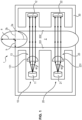
- FIG. 1 is schematically represented the arrangement of the apparatus 1 proposed for determining the hematocrit level of a liquid circulating in a tubular portion 2.
- the device 1 for determining the hematocrit level proposed can be used to determine the hematocrit level of any type of liquid but it is particularly suitable for determining the hematocrit level of hemorrhagic liquid such as human blood, in circulation in a tube, for example a flexible tube used as standard in a hospital environment.
- the proposed device 1 makes it possible to determine the hematocrit level of a liquid in a non-invasive manner, that is to say without having to intervene on the liquid as such, which can therefore continue to circulate freely in the tubing.
- the proposed apparatus 1 comprises at least two transceiver assemblies (10; 20), each transceiver assembly (10; 20) comprising a light source (11; 21) and a light sensor (12; 22). These two transmitter-receiver assemblies (10; 20) are used to determine the hematocrit level of the liquid circulating in the tubing, the light beams passing through the liquid to be analyzed being used to calculate the hematocrit level of the liquid.
- the fact of having two transceiver assemblies (10; 20) makes it possible to increase the reliability of the device 1 since the measurements of the two light sensors (12; 22) can be correlated. In addition, this allows for redundancy which can be advantageous in the event of failure of one of the two transceiver assemblies (10; 20).
- the light source (11; 21) of each of the two transceiver assemblies (10; 20) is configured to emit light beams at a wavelength emission chosen to correspond to an isosbestic point of hemoglobin. It is understood that an isosbestic point corresponds to a wavelength value at which the total absorbance of a sample remains constant during a chemical reaction or a possible change of state of this sample. More precisely, an isosbestic point is a wavelength ( ⁇ iso ) at which the total absorbance of a chromophore remains constant regardless of the state in which it is found. At this precise point several chromophores have the same molar extinction coefficient ( ⁇ ( ⁇ iso )).
- hemoglobin There are several isosbestic points for hemoglobin.
- oxyhemoglobin and deoxyhemoglobin have isosbestic points at 550 nm, 570 nm and near 810 nm wavelength. At these wavelengths ( ⁇ iso ), we can therefore obtain a measurement linked to the total volume of hemoglobin, since the absorption of light at this wavelength is independent of the oxygenated or reduced state in which it occurs. finds hemoglobin.
- a wavelength near 1300 nm corresponds to another isosbestic point of hemoglobin.
- Wavelengths above 1400 nm are also generally isosbestic to hemoglobin, particularly wavelengths between 1400 nm and 2200 nm.
- An advantage of these specific wavelengths is that the absorption of light at these wavelengths is essentially the same in water and in plasma.
- the hematocrit rate determined at these wavelengths will be the same whatever the matrix carrying the red blood cells, whether this matrix is mainly composed of plasma or whether it is mainly composed of water. This is particularly true for wavelengths between 1400 nm and 1700 nm and between 1900 nm and 2200 nm.
- Such wavelengths are therefore particularly advantageous when the hemorrhagic liquid for which the hematocrit level is to be determined is diluted more or less strongly with an aqueous solution, such as a saline solution for example.
- one of the light sources (11; 21) of the transceiver assemblies (10; 20) can for example be configured to emit light beams at a wavelength between 780 nm and 840 nm, preferably a wavelength between 800 nm and 820 nm, and more preferably a wavelength equal to 810 nm.
- One of the light sources (11; 21) of the transceiver assemblies (10; 20) can for example be configured to emit light beams at a wavelength between 1270 nm and 1330 nm, preferably a length d wave between 1290 nm and 1310 nm, and more preferably a wavelength equal to 1300 nm.
- One of the light sources (11; 21) of the transceiver assemblies (10; 20) can for example be configured to emit light beams at a wavelength between 1450 nm and 1550 nm, preferably a length d wave between 1490 nm and 1510 nm, and more preferably a wavelength equal to 1500 nm.
- One of the light sources (11; 21) of the transceiver assemblies (10; 20) can for example be configured to emit light beams at a wavelength between 530 nm and 620 nm, preferably a length d wave between 550 nm and 600 nm, and more preferably a wavelength equal to 550 nm, 570 nm or 590 nm.
- the respective light sources (11; 21) of the two transceiver assemblies (10; 20) can be configured to emit light beams at two identical emission wavelengths, but it is advantageous that the two light sources (11 ; 21) are configured to emit light beams at two different emission wavelengths.
- the use of two light sources operating at different wavelengths allows better correlation of the measurements with a view to calculating the hematocrit rate of the liquid circulating in the tubular portion 2.
- one of the light sources (11; 21) of the transceiver assemblies (10; 20) is configured to emit light beams at a wavelength between 780 nm and 840 nm, preferably a wavelength between 800 nm and 820 nm, and more preferably a wavelength equal to 810 nm, while the other light source (11; 21) is configured to emit light beams at a length of wave between 1270 nm and 1330 nm, preferably a wavelength between 1290 nm and 1310 nm, and more preferably a wavelength equal to 1300 nm.
- light-emitting diodes (abbreviated in English as LED for “light-emitting diode”) can be used, such as that offered by the company “THORLABS” under the reference LED810L (for an 810 nm light source) and that offered by the company “MARKTECH Optoelectronics” under the reference MTE1300NN1-WRC (for a 1300 nm light source).
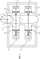
- the light source (11; 21) and the light sensor (12; 22) of each transceiver assembly (10; 20) are provided to be arranged on either side of the tubular portion 2 at the level of a liquid circulation zone, which forms a detection zone of the transceiver assemblies (10; 20).
- Such an arrangement will allow measurement in transmission, that is to say that the light beams coming from each of the light sources (11; 21) are intended to pass through the liquid circulating in the tubular portion 2 before reaching the light sensors (12; 22) of the corresponding transceiver assembly (10; 20).
- each light beam coming from the light sources (11; 21) passes through a first wall of the tubular portion 2, called entry wall 201, then transverses the liquid circulating in the tubular portion 2, then passes through a second wall of the tubular portion 2, opposite the inlet wall 201 and called outlet wall 202.
- the light sources (11; 21) of the transmitter-receiver assemblies (10; 20) are positioned on the same side in relation to the tubular portion 2. This makes it possible in particular to facilitate the assembly of the different elements forming the device 1 for determining the hematocrit level and improves the compactness of the device 1 since similar elements and therefore of the same size are placed on the same side.
- each transmitter-receiver assembly (10; 20) further comprises a collimation system (13; 23) provided for collimation of the light beam emitted from the corresponding light source (11; 21) in the direction of the light sensor (12; 22) associated.
- collimation systems (13; 23) are configured for infinite collimation of the light beams coming from the light sources (11; 21) in the direction of the tubular portion 2.
- the optical path of these light beams is modified by crossing the entrance wall 201 of the tubular portion 2, by passing through the liquid circulating in the tubular portion 2, then by passing through the inlet wall 202 of the tubular portion 2. Collimating the light beams coming from the light sources (11; 21) to infinity makes it possible to converge the light beams in the direction of the light sensors (12; 22) of the transmitter-receiver assemblies (10; 20) whatever the shape of the tubular portion, in particular if this tubular portion 2 is not deformed with a section circular or if this tubular portion 2 is deformed with an ellipsoidal section.
- Each collimation system (13; 23), or at least one of the two, can for example comprise a set of upstream lens(es) (131; 231) having a focal plane and being positioned between the light source (11; 21) and the corresponding light sensor (12; 22) on the side of the light source (11; 21) relative to the tubular portion 2.
- a set of upstream lens(es) (131; 231) can be made up of a single lens having a single focal plane or a plurality of lenses whose assembly makes it possible to define a global focal plane.
- the light source (11; 21) can be positioned more or less 10 mm from the focal plane of the upstream lens assembly, and preferably in the focal plane of the lens assembly. (s) upstream.
- each collimation system (13; 23), or at least one of the two may comprise a set of downstream lens(es) having a focal plane and being positioned between the light source (11; 21) and the corresponding light sensor (12; 22) on the side of the light sensor (12; 22) relative to the tubular portion 2.
- a set of downstream lens(es) may consist of a single lens having a single focal plane or a plurality of lenses whose assembly makes it possible to define a global focal plane.
- the light sensor (12; 22) can for example be positioned more or less 10 mm from the focal plane of the assembly of downstream lens(es) (132; 232), and preferably in the focal plane of the assembly of downstream lens(es) (132; 232).
- this set of downstream lens(es) makes it possible to converge these light beams on the light sensor (12; 22 ) corresponding.
- the assembly of downstream lens(es) is positioned so that the light beams exiting the outlet wall 202 of the tubular portion 2 converge at more or less 10 mm from the focal plane of the assembly of downstream lens(es), and preferably in the focal plane of this assembly of downstream lens(es).
- this set of downstream lens(es) makes it possible to infinitely collimate the light beams in the direction of the corresponding light sensor (12; 22).
- the assembly of upstream lens(es) and/or the assembly of downstream lens(es) could be mounted in the device 1 so as to be able to be translated along the general optical axis, for example from automated manner, so as to be able to vary their positioning according to the dimensions and the deformation of the tubular portion 2 in which circulates the liquid whose hematocrit level is to be determined.
- each collimation system (13; 23), or at least one of the two may comprise an upstream diaphragm (133; 233) positioned between the corresponding light source (11; 21) and light sensor (12; 22). on the side of the light source (11; 21) relative to the tubular portion 2.
- Such an upstream diaphragm (133; 233) is configured and arranged in the device 1 to allow a central portion of the light beams emitted by the source to pass light (11; 21) in the direction of the light sensor (12; 22) and to stop a peripheral portion of the light beams emitted by the light source (11; 21).
- each collimation system (13; 23), or at least one of the two may comprise a downstream diaphragm (134; 234) positioned between the corresponding light source (11; 21) and light sensor (12; 22). on the side of the light sensor (12; 22) relative to the tubular portion 2.
- a downstream diaphragm (134; 234) is configured and arranged in the device 1 to allow a central portion of the light beams transmitted through the portion to pass tubular 2 towards the light sensor (12; 22) and to stop a peripheral portion of the light beams transmitted through the tubular portion 2.
- an upstream diaphragm (133; 233) and/or a downstream diaphragm (134; 234) is particularly advantageous since this makes it possible to avoid the light beams which interfere with the reception of the light sensors (12; 22). ) and therefore disrupt the measurements of the device 1.
- Such diaphragms make it possible, for example, to reduce the noise caused by the light beams reflected, diffracted or diffused by the tubular portion 2.
- the upstream diaphragm (133; 233) allows the light beam emitted from the light source (11; 21) to be selected and centered on the tubular portion 2 in order to minimize its diffusion and reflection.
- the downstream diaphragm (134; 234) makes it possible to further refine the signal received by the light sensor (12; 22) since it only allows the central beams transmitted by the tubular portion 2 to pass while cutting off the parasitic beams such as that the light beams reflected, diffracted or diffused by the tubular portion 2.
- Another advantage of the use of diaphragm(s) is that they make it possible to improve the level of reception by the light sensors (12; 22) without having to to increase the power of the light sources (11; 21) which makes it possible to increase the lifespan of the components of the device 1.
- the use of diaphragms, in particular the upstream diaphragm, will be even more more preferred that the emission cone of the light sources (11; 21) will be tightened, that is to say that the angles ( ⁇ 1; ⁇ 2) of the emission cones of the light sources (11; 21) will be low, so that a major part of the light beam coming from the light sources (11; 21) is concentrated by cutting only the parasitic peripheral light beams.
- each collimation system (13; 23), or at least one of the two may comprise an upstream filter (135; 235) positioned between the corresponding light source (11; 21) and light sensor (12; 22). on the side of the light sensor (12; 22) relative to the tubular portion 2.
- Such a downstream filter (136; 236) of the collimation system (13; 23) of a transmitter-receiver assembly (10; 20) is provided to filter at least the emission wavelength of the light source (11; 21) of the other transceiver assembly (10; 20).
- the downstream filter (136; 236) of the collimation system (13; 23) of a transceiver assembly (10; 20) is designed to block all light beams not at the wavelength of interest, that is to say the emission wavelength of the light source (11; 21). ) corresponding.
- an upstream filter (135; 235) and/or a downstream filter (136; 236) is particularly advantageous in that it makes it possible to limit the light beam received by a particular light sensor (12; 22). only the light beams coming from the corresponding light source (11; 21), while avoiding disturbance by parasitic light beams coming from the other light source (11; 21), or even parasitic beams coming from the ambient light.
- the emission cones of the light sources (11; 21) defined by the angles ( ⁇ 1; ⁇ 2) are as tight as possible so that the intensity of the light beam centered on the tubular portion 2 is as strong as possible without having to use too high an emission power for the light sources (11; 21) so as not to reduce the lifespan of the elements forming the device 1.
- angles ( ⁇ 1; ⁇ 2) of the emission cones of the light sources (11; 21) are preferably between 1° and 25°, and preferably between 5° and 20°, and more preferably between 10°. ° and 15°. It should be noted that the angle ( ⁇ 1; ⁇ 2) of the emission cone may depend on the emission wavelength used for the light source (11; 21).
- the angle ( ⁇ 1; ⁇ 2) of the emission cone can for example be of the order of 13° ( ⁇ 1°) .
- the angle ( ⁇ 1; ⁇ 2) of the emission cone can for example be of the order of 15° ( ⁇ 1°) .
- the proposed device 1 for determining the hematocrit level is intended to be positioned around an existing tubular portion, for example a tubing or flexible tube used in a hemorrhagic fluid treatment system, so as to allow determination of the hematocrit level in a non-invasive manner.
- the device 1 comprises a support assembly 30 on which the elements forming the device 1, in particular the transceiver assemblies (10; 20), are mounted.
- the support assembly 30 is preferably intended to be positioned around the tubular portion.
- Such a support assembly 30 can for example comprise a single support 31 as illustrated in figures 1 to 6 , this support 31 having a groove 32 intended to receive the tubular portion 2.
- the light sources (11; 21) and the light sensors (12; 22) are then arranged on the support 31 on either side of the groove 32 .
- the support assembly may further comprise a cover 33 intended to at least partially cover the groove 32 of the support 31.
- a cover 33 is intended to prevent the withdrawal of the tubular portion 2 which would be inserted in the groove 32, thus having a lock function.
- the cover 33 comprises a compression portion 331 intended to compress the tubular portion 2 positioned in the groove 32.
- This compression portion 331 is adapted to at least hold the tubular portion 2 in position in the groove 32 of the support 31 of the device 1.
- the support assembly 30 comprises an envelope 34 intended to cover the support 30, in particular to protect the elements of the device 1.
- Such an envelope 34 forms the external casing of the device 1.
- Such a cover 33 can for example be mounted in an articulated manner relative to the support 31.
- the cover 33 is for example assembled on the envelope 34 in an articulated manner and arranged so as to be facing the groove 32 of the support 31.
- the cover 33 and/or the envelope 34 have external surfaces making it possible to protect the transceiver assemblies (10; 20) from external disturbances, in particular from ambient light.
- the cover 33 and/or the envelope 34 also preferably have external surfaces preventing the reflection of light rays due to the light sources (11; 21) and not directed towards the light sensors (12; 22), such as for example all scattered, diffracted, reflected rays.
- the external surfaces of the cover 33 and/or the envelope 34 are designed to absorb these light rays.
- the cover 33 and/or the envelope 34 can for example be formed from a completely opaque material.
- the cover 33 and/or the envelope 34 are also preferably provided to guarantee sealing of the device 1, in particular sealing against liquids in order to protect all the sensitive elements of the device 1, in particular the electronic components.
- Each element forming the transceiver assemblies (10; 20) can be mounted individually on the support 31 in order to form the device 1.
- the uniqueness of the support 31 makes it possible to guarantee that the elements are maintained in position relative to each other. but the assembly itself can be difficult.
- To facilitate the assembly of the elements forming the transmitter-receiver assemblies (10; 20) while guaranteeing positioning precisely it is proposed to use mounting barrels (311; 321; 312; 322) in which the elements forming the transmitter-receiver assemblies (10; 20) are pre-assembled, which mounting barrels (311; 321; 312; 322) then being inserted into mounting cavities provided in the support 31, these mounting cavities having a complementary shape to the mounting barrels (311; 321; 312; 322), allowing for example forceful insertion of the mounting barrels ( 311; 321; 312; 322) in these mounting cavities.
- each mounting barrel (311; 321; 312; 322) one or more cavities are provided for receiving the elements forming the transmitter-receiver assemblies (10; 20), each cavity being dimensioned to receive the specific element to be positioned.
- Each mounting barrel (311; 312) has a substantially elongated shape, preferably cylindrical, and comprises several cavities (3111, 3112, 3113, 3114; 3121, 3122, 3123, 3124) connected to each other so as to form a through opening through the mounting barrel (311; 312).
- two adjacent cavities (3111, 3112, 3113, 3114; 3121, 3122, 3123, 3124) have sections of different size and/or shape so that the cooperation of cavities (3111, 3112, 3113, 3114; 3121, 3122, 3123, 3124) adjacent makes it possible to form a space for receiving an element forming the collimation system (13; 23) or the light source (11; 21).
- the cavities (3111, 3112, 3113, 3114; 3121, 3122, 3123, 3124) are therefore formed in the mounting barrel (311; 312) in order to allow precise positioning of the elements forming the transmitter-receiver assemblies (10; 20 ).
- the collimation system (13; 23) comprises a lens (131; 231) which can be inserted into the end cavity (3114; 3214) and abut against the shoulder formed by the cavity (3113; 3213) adjacent.
- the cavity (3113; 3213) on which the lens (131; 231) abuts has a length corresponding to the desired distance between the lens (131; 231) and the corresponding light source (11; 21). Preferably, this length is chosen so that the light source (11; 21) is in the focal plane of the lens (131; 231).
- This cavity (3113; 3213) therefore has a remote maintenance function.
- the light source (11; 21) is intended to be inserted from the other end cavity (3111; 3211) into the adjacent cavity (3112; 3212), this cavity (3112; 3212) also being adjacent to the distance-keeping cavity (3113; 3213).
- the light source (11; 21) may for example comprise a protuberance coming into abutting against a shoulder formed between the cavity (3112; 3212) for receiving the light source (11; 21) and the end cavity (3111; 3211).
- the lens (131; 231) is pre-assembled in the mounting barrel (311; 312), it is possible to insert this mounting barrel (311; 312) into the mounting cavity provided for this purpose in the support 30.
- the figure 8 illustrates this insertion of the mounting barrels (311; 321; 312; 322) in the mounting cavities provided for this purpose in the support 31.
- the light sources (11; 21) and the light sensors (12; 22) are mounted in the cavities provided in the mounting barrels (311; 321; 312; 322) once these mounting barrels (311; 321; 312; 322) have been inserted into the support 30. It can however be planned to pre-mount the light sources (11; 21) and the light sensors (12; 22) in the cavities provided in the mounting barrels (311; 321; 312; 322) before these mounting barrels (311; 321; 312; 322) are inserted into the support 31.
- the support assembly 30 comprises two supports intended to be assembled with one another by surrounding the tubular portion 2.
- An upstream support can thus be provided on which the light sources (11; 21) and all elements of the transmitter-receiver assemblies (10; 20) are arranged on which are arranged to be on the side of the light source (11; 21) corresponding to to the tubular portion 2.
- a downstream support distinct from the upstream support is also provided, on which are arranged the light sensors (12; 22) and all elements of the transceiver assemblies (10; 20) intended to be on the side of the corresponding light sensor (12; 22). relative to the tubular portion 2.
- downstream and upstream supports have complementary shapes designed to be coupled so as to enclose the tubular portion 2.
- the flow of the liquid circulating in the tubular portion 2 is not or only slightly modified so as not to have a negative impact on this liquid.
- a hemorrhagic liquid such as blood
- too significant a change in the flow due for example to a substantial constriction of the tubular portion 2 at the level of the detection zone of the device 1 could create hemolysis, which is to avoid for effective treatment of hemorrhagic fluid.
- the tubular portion 2 at the level of the detection zone it is not desired for the tubular portion 2 at the level of the detection zone to be flattened so that the inlet wall 201 and the outlet wall 202 are substantially parallel to one another relative to the other since this would create too much hemolysis for the treatment of the hemorrhagic fluid.
- the sets transceiver (10; 20) are preferably arranged in the apparatus 1 for measurement in transmission through curved walls of the tubular portion 2, that is to say curved walls.
- the simplest way to avoid a risk of hemolysis is not to deform the tubular portion 2.
- the pronounced curvatures of the circular section of the tubular portion 2 can, however, disrupt the transmission of the light beams from the light sources (11; 21) towards the light sensors (12; 22).
- the proposed apparatus and method are intended for determining the hematocrit level and/or the hemoglobin level of the circulating liquid without deformation of the tubular portion.
- a system for deforming the tubular portion 2 positioned opposite the transmitter-receiver assemblies (10; 20) can also be provided.
- the tubular portion at which the transmission measurement is carried out retains a certain curvature, and is therefore not flattened.
- the deformation system is designed to deform the circular section of the tubular portion into an ellipsoidal section.
- the deformation system can for example use the cooperation of the cover 33, and more specifically of the compression portion 331, with the shape of the groove 32.
- the groove 32 can in fact have a section of substantially ellipsoidal shape and the compression portion 331 is intended to compress the tubular portion 2 so that it deforms and substantially matches the shape of the groove 32.
- the ellipsoidal section of the deformed tubular portion 2 is defined by a major axis 2a and a minor axis 2b perpendicular to the major axis.
- the deformation is such that the light sources (11; 21) and all elements of the transmitter-receiver assemblies (10; 20) intended to be on the side of the light source (11; 21) corresponding relative to the tubular portion 2 are positioned on one side of the major axis 2a, and the light sensors (12; 22) and all elements of the transceiver assemblies (10; 20) intended to be on the side of the light sensor ( 12; 22) corresponding to the tubular portion 2 are positioned on the other side of the major axis 2a.
- the ellipsoidal section of the deformed tubular portion 2 is further defined by a large radius (Ra) along the major axis 2a and by a small radius (Rb) along the minor axis 2b, the ellipsoidal section having, in a deformed state of the tubular portion, a small radius (Rb) having a length between 30% and 70%, and preferably of the order of 50%, of the radius of the circular section of the tubular portion 2 in the non-deformed state.
- the transceiver assemblies (10; 20) are designed to be coupled to a central processing unit enabling them to be controlled, both in transmission and reception, but also enabling the information from the transceiver assemblies (10; 10); 20).
- the apparatus 1 may for example comprise a control system connected to the central processing unit and configured to control the light sources (11; 21) of the transceiver assemblies (10; 20).
- the device 1 may further comprise a processing system connected to the central processing unit and configured to recover and process the signals coming from the light sensors (12; 22) of the transceiver assemblies (10; 20), in particular in order to to determine the hematocrit level of the circulating liquid.
- a processing system connected to the central processing unit and configured to recover and process the signals coming from the light sensors (12; 22) of the transceiver assemblies (10; 20), in particular in order to to determine the hematocrit level of the circulating liquid.
- the light sources (11; 21) and the light sensors (12; 22) of the transceiver assemblies (10; 20) are thus preferably connected to an electronic circuit 40 allowing the control system to control the light sources (11; 21) on the one hand, and for the processing system to recover the signals received by the light sensors (12; 22) on the other hand.
- the electronic circuit 40 comprises a first electronic card 41 intended to be connected to the light sources (11; 21) and a second electronic card 42 intended to be connected to the light sensors (12; 22).
- Each of these first and second electronic cards (41; 42) are preferably coupled to the light sources (11; 21) and to the light sensors (12; 22) respectively once these have been mounted in the support 31.
- the electronic circuit 40 further comprises a third electronic card 43 connecting the first and second electronic cards (41; 42).
- This third electronic card 43 can also form a wall of the device 1 forming with the envelope 34 the external casing of the device 1.
- the control system is preferably configured so that the light sources (11; 21) emit at the same time, that is to say concomitantly.
- This makes it possible, for example, to have continuous measurements, which makes it possible to get as close as possible to real-time and continuous detection.
- This also makes it possible to increase the reliability of the detection since it is possible to correlate the detection of the two light sensors (12; 22) at the same time t, and not one at a time t and the other at a time t+n.
- the correlation is also simplified.
- the control system of the device 1 can thus comprise means for synchronizing the light sources (11; 21), the control system therefore being configured to synchronize the emission of the light sources (11; 21).
- the control system can therefore comprise means for modifying the power emitted by the light sources (11; 21), the control system therefore being configured to modify the power emitted by the light sources (11; 21) .
- This modification of the emission power of the light sources (11; 21) can for example depend on the value of the hematocrit rate detected for the liquid circulating in the tubular portion 2.
- the light signals received by the light sensors (12; 22) of the transceiver assemblies (10; 20) are intended to be processed by the processing system to determine the hematocrit rate of the liquid circulating in the tubular portion around which the device 1 was positioned.
- the value obtained D pw is a linear function of the hematocrit level.
- the value obtained D pw is also a function of the hematocrit level in a linear manner.
- a device 1 for determining the hematocrit level operating reliably for a wide range of hematocrit levels, which is particularly advantageous when the device 1 is used for example in a set of treatment of hemorrhagic fluid where the hemorrhagic fluid to be treated generally has a low hematocrit level (typically less than 20%, or even less than 10%) before starting treatment while the target hematocrit level to be achieved for the hemorrhagic fluid treated is high, for example at least 35%, or even at least 45%, and sometimes at least 50%.
- control system is provided to modify the emission power of all the light sources (11; 21) of the transmitter-receiver assemblies (10; 20) during the measurement of the hematocrit rate as a function of the rate of hematocrit calculated for the liquid.
- the emission power of the light sources (11; 21) is controlled independently for each of the light sources (11; 21). This independent control is particularly advantageous when the light sources (11; 21) are different, in particular when the emission wavelengths are different.
- the light sources (11; 21) it is advantageous not to use the light sources (11; 21) at 100% of their capacity. Indeed, it is preferable to use the light sources (11; 21) at an emission power lower than the maximum power of the sources luminous (11; 21) to increase the longevity of the device 1 on the one hand, but also to avoid possible degradation of the elements of the device 1, or heating of the circulating liquid to be analyzed for example.
- the device 1 To increase the sensitivity of the device 1 whatever the value of the hematocrit level of the circulating liquid, and without having to modify the parameters of the light sensor (12; 22), it is also advantageous to vary the power emission of the light sources (11; 21) as a function of the hematocrit level.
- the higher the hematocrit level the more the light signal coming from the light sources (11; 21) risks being absorbed by the circulating liquid, which can be compensated by an increase in the intensity of the hematocrit. emission of the light sources (11; 21) for similar reception intensity levels at the level of the light sensors (12; 22).
- the emission power of the light sources (11; 21) is therefore controlled as a function of the detection level of the light sensors (12; 22) correlated to the measured hematocrit level.
- the emission power of the light sources (11; 21) can be controlled as a function of the non-linearity threshold below which the value measured by the light sensors (12; 22) does not make it possible to calculate the rate hematocrit with sufficient reliability.
- the emission power of the light sources (11; 21) so that the received signal has a power greater than the non-linearity threshold but as close as possible to this non-linearity threshold, while being of a sufficient level according to the hematocrit level measured.
- the emission power of the light sources (11; 21) can be controlled as a function of the saturation threshold of the light sensor (12; 22) beyond which the light signal received at the light sensor ( 12; 22) is not measurable.
- each light source (11; 21) at 100% of their maximum emission power level, it is advantageous to use an emission power for the light sources (11 ; 21) between 10% and 60% of the maximum emission power of said light sources.
- the proposed device 1 is intended to allow determination of a wide range of hematocrit levels, in particular both for hematocrit levels as low as 5%, or even less than 5%, as well as for levels of high hematocrit, of the order of 50%, or even of the order of 60% or higher.
- the device 1 When using the device 1 to determine the hematocrit level of a circulating liquid, it is advantageous to gradually increase the power emission of at least one of the light sources (11; 21), and preferably of all the light sources (11; 21), in particular as the hematocrit level of the liquid increases.
- the emission power of at least one of the light sources (11; 21) is increased from a threshold value of the hematocrit level measured for the liquid.
- the emission power of at least one of the light sources (11; 21), and preferably of all the light sources (11; 21), can for example be fixed at a value between 10% and 30%, preferably substantially equal to 20%, of the maximum emission power of the corresponding light source.
- the emission power of at least one of the light sources (11; 21), and preferably of all the light sources (11; 21), can be example be set at a value between 30% and 100%, preferably substantially equal to 50%, of the maximum emission power of the corresponding light source.
- the emission power of the light sources can also be modified during the measurement of the hematocrit level depending on the presence or absence of liquid in the tubular portion 2 and/or the nature of said liquid.
- the tubular portion is devoid of liquid, it is preferable that the light source(s) (11; 21) are maintained at a minimum or even zero emission level.
Description
La présente divulgation concerne un appareil et une méthode pour la détermination d'un paramètre sanguin d'un liquide en circulation, en particulier pour la détermination du taux d'hémoglobine et/ou du taux d'hématocrite du liquide en circulation. La présente divulgation trouve une application particulièrement avantageuse pour des applications médicales, par exemple pour l'analyse de liquide hémorragique en circulation dans un tube.The present disclosure relates to an apparatus and a method for determining a blood parameter of a circulating liquid, in particular for determining the hemoglobin level and/or the hematocrit level of the circulating liquid. The present disclosure finds a particularly advantageous application for medical applications, for example for the analysis of hemorrhagic fluid circulating in a tube.
Il existe de nombreuses applications médicales pour lesquelles le suivi des paramètres sanguins permettant de qualifier le liquide hémorragique du patient est nécessaire. Suivre l'évolution du taux d'hémoglobine et/ou du taux d'hématocrite d'un liquide hémorragique peut par exemple être utile dans certaines interventions, notamment chirurgicales. En particulier, lorsque le liquide hémorragique d'un patient doit subir un traitement spécifique, il est avantageux de pouvoir suivre en continu l'évolution de ces paramètres sanguins.There are many medical applications for which monitoring blood parameters to qualify the patient's hemorrhagic fluid is necessary. Monitoring the evolution of the hemoglobin level and/or the hematocrit level of a hemorrhagic fluid can for example be useful in certain interventions, particularly surgical ones. In particular, when a patient's hemorrhagic fluid must undergo specific treatment, it is advantageous to be able to continuously monitor the evolution of these blood parameters.
Un exemple particulier et non limitatif où il est utile de pouvoir suivre l'évolution des paramètres sanguins est le traitement de liquide hémorragique en vue d'une autotransfusion de sang chez un patient. L'autotransfusion ou transfusion autologue, à savoir la transfusion chez un patient de son propre sang, est de plus en plus pratiquée lors d'interventions chirurgicales, puisqu'elle évite les incompatibilités qui peuvent survenir lors de transfusions homologues ou allogéniques. L'autotransfusion évite de plus la transmission de maladies infectieuses.A particular and non-limiting example where it is useful to be able to follow the evolution of blood parameters is the treatment of hemorrhagic fluid with a view to autotransfusion of blood in a patient. Autotransfusion or autologous transfusion, namely the transfusion of a patient's own blood, is increasingly practiced during surgical interventions, since it avoids the incompatibilities that can occur during homologous or allogeneic transfusions. Autotransfusion also prevents the transmission of infectious diseases.
Pour un bon fonctionnement de ces systèmes de traitement de liquide hémorragique, il est impératif de pouvoir suivre en temps réel l'évolution de la concentration en hémoglobine ou du taux d'hématocrite dans le liquide en cours de traitement puisque l'évolution des paramètres sanguins de ce liquide peut permettre de piloter le système de traitement. Une des difficultés réside dans le fait que le liquide dont on souhaite connaitre le taux d'hémoglobine et/ou d'hématocrite est en circulation, en général dans des tubulures souples, ce qui vient complexifier la détection. En outre, il est nécessaire d'appliquer des méthodes de détection spécifiques pour compenser les pertes de sensibilité de la détection dues au mouvement du liquide. Par ailleurs, les systèmes de traitement de liquide hémorragique (notamment en vue d'autotransfusion) étant en général utilisé dans des situations d'urgence, il est important que l'ensemble du système puisse être utilisable immédiatement, en évitant dans la mesure du possible toute étape de calibration préalable, y compris s'agissant du composant permettant de déterminer le taux d'hémoglobine et/ou d'hématocrite du liquide hémorragique à traiter.For the proper functioning of these hemorrhagic fluid treatment systems, it is imperative to be able to monitor in real time the evolution of the hemoglobin concentration or the hematocrit level in the fluid being treated since the evolution of blood parameters of this liquid can be used to control the treatment system. One of the difficulties lies in the fact that the liquid for which we wish to know the hemoglobin and/or hematocrit level is in circulation, generally in flexible tubing, which complicates detection. Furthermore, it is necessary to apply specific detection methods to compensate for losses in detection sensitivity due to liquid movement. Furthermore, liquid treatment systems hemorrhagic (particularly for autotransfusion) being generally used in emergency situations, it is important that the entire system can be used immediately, avoiding as far as possible any prior calibration step, including s acting as the component making it possible to determine the hemoglobin and/or hematocrit level of the hemorrhagic fluid to be treated.
Dans l'article intitulé «
Un but de la présente invention est de proposer un appareil de détermination d'un paramètre sanguin tel que la concentration en hémoglobine (appelée également taux d'hémoglobine) et/ou le taux d'hématocrite pouvant être utilisé pour un liquide en circulation dans une portion tubulaire ayant un diamètre quelconque, notamment un tube souple utilisé en milieu médical.An aim of the present invention is to provide an apparatus for determining a blood parameter such as the hemoglobin concentration (also called hemoglobin level) and/or the hematocrit level which can be used for a liquid circulating in a tubular portion having any diameter, in particular a flexible tube used in a medical environment.
Un autre but de l'invention est de proposer un appareil de détermination du taux d'hémoglobine et/ou du taux d'hématocrite d'un liquide en circulation dans une portion tubulaire présentant une fiabilité accrue, et permettant notamment des mesures dans une gamme large des taux. Par exemple, un but est de permettre des mesures de taux d'hématocrite aussi bien pour des taux d'hématocrite faibles, c'est-à-dire inférieurs ou égaux à 30%, que pour des taux d'hématocrite élevés, c'est-à-dire supérieurs à 30%. En particulier, un but de la présente invention est de proposer un appareil permettant de déterminer des taux d'hématocrite au moins compris dans la gamme de 5% à 60%, et notamment entre 20% et 50%.Another aim of the invention is to propose an apparatus for determining the hemoglobin level and/or the hematocrit level of a liquid circulating in a tubular portion having increased reliability, and in particular allowing measurements in a range wide rates. For example, one goal is to allow measurements of hematocrit levels both for low hematocrit levels, that is to say less than or equal to 30%, and for high hematocrit levels, i.e. that is to say greater than 30%. In In particular, an aim of the present invention is to provide an apparatus making it possible to determine hematocrit levels at least in the range from 5% to 60%, and in particular between 20% and 50%.
Un autre but de la présente invention est de proposer un appareil de détermination du taux d'hémoglobine et/ou du taux d'hématocrite d'un liquide en circulation dans une portion tubulaire qui peut être positionné sur cette portion tubulaire de manière simple, sans avoir notamment à modifier cette portion tubulaire, et sans avoir à stopper la circulation du liquide le cas échéant. Avantageusement, l'appareil de détermination du taux d'hémoglobine et/ou du taux d'hématocrite proposé peut être directement utilisé sur un système de traitement d'un liquide, par exemple un système de traitement de liquide hémorragique pour de l'autotransfusion, en utilisant les tubulures préexistantes dans le système de traitement, sans avoir à démonter les éléments de ce système de traitement notamment.Another aim of the present invention is to provide an apparatus for determining the hemoglobin level and/or the hematocrit level of a liquid circulating in a tubular portion which can be positioned on this tubular portion in a simple manner, without having in particular to modify this tubular portion, and without having to stop the circulation of the liquid if necessary. Advantageously, the device for determining the hemoglobin level and/or the hematocrit level proposed can be directly used on a liquid treatment system, for example a hemorrhagic liquid treatment system for autotransfusion, by using the pre-existing tubing in the treatment system, without having to dismantle the elements of this treatment system in particular.
Encore un but de la présente invention est de proposer un appareil de détermination du taux d'hémoglobine et/ou du taux d'hématocrite pouvant être utilisé pour un liquide circulant dans une portion tubulaire à un débit important (typiquement supérieur à 1000 ml/min, par exemple de l'ordre de 2000 ml/min) sans toutefois venir substantiellement perturber le flux de ce liquide en circulation, pour éviter de possibles effets néfastes sur le liquide, par exemple pour éviter de créer une hémolyse pour une circulation de liquide hémorragique.Yet another aim of the present invention is to provide an apparatus for determining the hemoglobin level and/or the hematocrit level which can be used for a liquid circulating in a tubular portion at a high flow rate (typically greater than 1000 ml/min). , for example of the order of 2000 ml/min) without however substantially disturbing the flow of this circulating liquid, to avoid possible harmful effects on the liquid, for example to avoid creating hemolysis for a circulation of hemorrhagic liquid .
Un autre but de la présente invention est de proposer un procédé de détermination du taux d'hémoglobine et/ou du taux d'hématocrite d'un liquide en circulation dans une portion tubulaire, fiable, simple à mettre en oeuvre, et permettant des mesures dans une gamme large de taux, en particulier aussi bien pour des taux d'hématocrite faibles, c'est-à-dire inférieurs ou égaux à 30%, que pour des taux d'hématocrite élevés, c'est-à-dire supérieurs à 30%. En particulier, un but de la présente invention est de proposer un procédé permettant de déterminer des taux d'hématocrite au moins compris dans la gamme de 5% à 60%, et notamment entre 20% et 50%.Another object of the present invention is to propose a method for determining the hemoglobin level and/or the hematocrit level of a liquid circulating in a tubular portion, reliable, simple to implement, and allowing measurements in a wide range of levels, in particular both for low hematocrit levels, that is to say less than or equal to 30%, and for high hematocrit levels, that is to say higher at 30%. In particular, an aim of the present invention is to propose a method making it possible to determine hematocrit levels at least in the range from 5% to 60%, and in particular between 20% and 50%.
A cette fin, on propose un appareil de détermination du taux d'hématocrite et/ou du taux d'hémoglobine d'un liquide en circulation dans une portion tubulaire, comprenant :
- deux ensembles émetteur-récepteur, chaque ensemble émetteur-récepteur comprenant une source lumineuse et un capteur lumineux prévus pour être agencés de part et d'autre de la portion tubulaire au niveau d'une zone de circulation du liquide pour une mesure en transmission, de préférence à travers des parois incurvées de la portion tubulaire ;
- la source lumineuse de chacun des deux ensembles émetteur-récepteur étant configurée pour émettre des faisceaux lumineux selon une longueur d'onde d'émission choisie pour correspondre à un point isobestique de l'hémoglobine ;
- chaque ensemble émetteur-récepteur comprenant en outre un système de collimation du faisceau lumineux émis depuis la source lumineuse correspondante en direction du capteur lumineux correspondant.
- two transceiver assemblies, each transceiver assembly comprising a light source and a light sensor intended to be arranged on either side of the tubular portion at a liquid circulation zone for transmission measurement, of preferably through curved walls of the tubular portion;
- the light source of each of the two transmitter-receiver assemblies being configured to emit light beams at an emission wavelength chosen to correspond to an isosbestic point of hemoglobin;
- each transceiver assembly further comprising a system for collimating the light beam emitted from the corresponding light source towards the corresponding light sensor.
On propose également un appareil de détermination du taux d'hématocrite et/ou du taux d'hémoglobine d'un liquide en circulation dans une portion tubulaire, comprenant :
- deux ensembles émetteur-récepteur, chaque ensemble émetteur-récepteur comprenant une source lumineuse et un capteur lumineux prévus pour être agencés de part et d'autre de la portion tubulaire au niveau d'une zone de circulation du liquide pour une mesure en transmission, de préférence à travers des parois incurvées de la portion tubulaire ;
- la source lumineuse de chacun des deux ensembles émetteur-récepteur étant configurée pour émettre des faisceaux lumineux selon une longueur d'onde d'émission choisie pour correspondre à un point isobestique de l'hémoglobine ;
- un système de traitement programmé pour déterminer le taux d'hématocrite et/ou du taux d'hémoglobine du liquide en fonction des signaux lumineux reçus par les capteurs lumineux des ensembles émetteur-récepteur ; et
- un système de contrôle comprenant des moyens de modification de la puissance émise par les sources lumineuses, le système de contrôle étant programmé pour modifier la puissance d'émission des sources lumineuses en fonction du taux d'hématocrite et/ou du taux d'hémoglobine déterminé pour le liquide.
- two transceiver assemblies, each transceiver assembly comprising a light source and a light sensor intended to be arranged on either side of the tubular portion at a liquid circulation zone for transmission measurement, of preferably through curved walls of the tubular portion;
- the light source of each of the two transmitter-receiver assemblies being configured to emit light beams at an emission wavelength chosen to correspond to an isosbestic point of hemoglobin;
- a processing system programmed to determine the hematocrit level and/or hemoglobin level of the liquid based on the light signals received by the light sensors of the transceiver assemblies; And
- a control system comprising means for modifying the power emitted by the light sources, the control system being programmed to modify the emission power of the light sources as a function of the hematocrit level and/or the determined hemoglobin level for the liquid.
Des aspects préférés mais non limitatifs de l'un ou l'autre de ces appareils, pris seuls ou en combinaison, sont les suivants :
- l'appareil comprend un ensemble support sur lequel sont montés les deux ensembles émetteur-récepteur, l'ensemble support étant prévu pour être positionné autour de la portion tubulaire ;
- les sources lumineuses respectives des deux ensembles émetteur-récepteur sont configurées pour émettre des faisceaux lumineux à deux longueurs d'onde d'émission différentes ;
- au moins une des sources lumineuses des ensembles émetteur-récepteur est configurée pour émettre des faisceaux lumineux selon une longueur d'onde d'émission choisie pour une absorption des faisceaux lumineux sensiblement identique dans de l'eau ou dans du plasma ;
- au moins un, et de préférence chaque, système de collimation comprend un ensemble de lentille(s) amont ayant un plan focal et étant positionné entre la source lumineuse et le capteur lumineux correspondants du côté de la source lumineuse par rapport à la portion tubulaire, la source lumineuse étant positionnée à plus ou moins 10 mm du plan focal de l'ensemble de lentille(s) amont, et de préférence dans plan focal de l'ensemble de lentille(s) amont ;
- au moins un, et de préférence chaque, système de collimation comprend un ensemble de lentille(s) aval ayant un plan focal et étant positionné entre la source lumineuse et le capteur lumineux correspondants du côté du capteur lumineux par rapport à la portion tubulaire, le capteur lumineux étant positionné à plus ou moins 10 mm du plan focal de l'ensemble de lentille(s) aval, et de préférence dans plan focal de l'ensemble de lentille(s) aval ;
- au moins un, et de préférence chaque, système de collimation comprend un ensemble de lentille(s) aval ayant un plan focal et étant positionné entre la source lumineuse et le capteur lumineux correspondants du côté du capteur lumineux par rapport à la portion tubulaire, l'ensemble de lentille(s) aval est positionné de sorte que les faisceaux lumineux en sortie de la paroi de sortie de la portion tubulaire convergent à plus ou moins 10 mm du plan focal de l'ensemble de lentille(s) aval, et de préférence dans plan focal de l'ensemble de lentille(s) aval ;
- au moins un, et de préférence chaque, système de collimation comprend un diaphragme amont positionné entre la source lumineuse et le capteur lumineux correspondants du côté de la source lumineuse par rapport à la portion tubulaire, le diaphragme amont étant prévu pour laisser passer une portion centrale des faisceaux lumineux émis par la source lumineuse en direction du capteur lumineux et pour stopper une portion périphérique des faisceaux lumineux émis par la source lumineuse ;
- au moins un, et de préférence chaque, système de collimation comprend un diaphragme aval positionné entre la source lumineuse et le capteur lumineux correspondants du côté du capteur lumineux par rapport à la portion tubulaire, le diaphragme aval étant prévu pour laisser passer une portion centrale des faisceaux lumineux transmis à travers la portion tubulaire en direction du capteur lumineux et pour stopper une portion périphérique des faisceaux lumineux transmis à travers la portion tubulaire ;
- au moins un, et de préférence chaque, système de collimation comprend un filtre amont positionné entre la source lumineuse et le capteur lumineux correspondants du côté de la source lumineuse par rapport à la portion tubulaire, et/ou un filtre aval positionné entre la source lumineuse et le capteur lumineux correspondants du côté du capteur lumineux par rapport à la portion tubulaire, les filtres amont et aval du système de collimation d'un ensemble émetteur-récepteur étant prévus pour filtrer au moins la longueur d'onde d'émission de la source lumineuse de l'autre ensemble émetteur-récepteur ;
- l'appareil est tel que la source lumineuse d'un premier des deux ensembles émetteur-récepteur est configurée pour émettre des faisceaux lumineux à une longueur d'onde comprise entre 780 nm et 840 nm, de préférence comprise entre 800 nm et 820 nm, et de préférence encore égale à 810 nm ; et la source lumineuse d'un deuxième des deux ensembles émetteur-récepteur est configurée pour émettre des faisceaux lumineux à une longueur d'onde comprise entre 1270 nm et 1330 nm, de préférence comprise entre 1290 nm et 1310 nm, et de préférence encore égale à 1300 nm ;
- les sources lumineuses des ensembles émetteur-récepteur sont positionnés du même côté par rapport à la portion tubulaire ;
- l'appareil comprend en outre un système de contrôle des ensembles émetteur-récepteur, le système de contrôle comprenant des moyens de synchronisation des sources lumineuses et/ou des moyens de modification de la puissance émise par les sources lumineuses ;
- les ensembles émetteur-récepteur sont assemblés sur un unique support ayant une rainure destinée à recevoir la portion tubulaire ;
- l'appareil comprend en outre un couvercle prévu pour recouvrir au moins partiellement la rainure, ledit couvercle comprenant une portion de compression destinée à maintenir en position la portion tubulaire positionnée dans la rainure ;
- les sources lumineuses et tous éléments des ensembles émetteur-récepteur prévus pour être du côté de la source lumineuse correspondante par rapport à la portion tubulaire sont assemblés sur un support amont, et les capteurs lumineux et tous éléments des ensembles émetteur-récepteur prévus pour être du côté du capteur lumineux correspondant par rapport à la portion tubulaire sont assemblés sur un support aval distinct du support amont, les supports aval et amont ayant des formes complémentaires prévues pour être couplées de manière à enserrer la portion tubulaire ;
- l'appareil comprend un système de déformation de la portion tubulaire en regard des ensembles émetteur-récepteur, le système de déformation étant prévu pour déformer une section circulaire de la portion tubulaire en une section ellipsoïdale ;
- les sources lumineuses et tous éléments des ensembles émetteur-récepteur prévus pour être du côté de la source lumineuse correspondante par rapport à la portion tubulaire sont positionnés d'un côté d'un grand axe définissant la section ellipsoïdale, et les capteurs lumineux et tous éléments des ensembles émetteur-récepteur prévus pour être du côté du capteur lumineux correspondant par rapport à la portion tubulaire sont positionnés de l'autre côté du grand axe définissant la section ellipsoïdale ;
- la section ellipsoïdale est définie par un grand rayon (Ra) le long du grand axe et par un petit rayon (Rb) le long d'un petit axe perpendiculaire au grand axe, la section ellipsoïdale ayant, dans un état déformé de la portion tubulaire, un petit rayon (Rb) ayant une longueur comprise entre 30% et 70%, et de préférence de l'ordre de 50%, du rayon de la section circulaire de la portion tubulaire en état non-déformé.
- the apparatus comprises a support assembly on which the two transceiver assemblies are mounted, the support assembly being intended to be positioned around the tubular portion;
- the respective light sources of the two transceiver assemblies are configured to emit light beams at two different emission wavelengths;
- at least one of the light sources of the transceiver assemblies is configured to emit light beams at a wavelength emission chosen for substantially identical absorption of light beams in water or in plasma;
- at least one, and preferably each, collimation system comprises a set of upstream lens(es) having a focal plane and being positioned between the corresponding light source and light sensor on the side of the light source relative to the tubular portion, the light source being positioned more or less 10 mm from the focal plane of the assembly of upstream lens(s), and preferably in the focal plane of the assembly of upstream lens(es);
- at least one, and preferably each, collimation system comprises a set of downstream lens(es) having a focal plane and being positioned between the corresponding light source and light sensor on the side of the light sensor relative to the tubular portion, the light sensor being positioned more or less 10 mm from the focal plane of the assembly of downstream lens(s), and preferably in the focal plane of the assembly of downstream lens(es);
- at least one, and preferably each, collimation system comprises a set of downstream lens(es) having a focal plane and being positioned between the corresponding light source and light sensor on the side of the light sensor relative to the tubular portion, the downstream lens assembly(s) is positioned so that the light beams exiting the outlet wall of the tubular portion converge at plus or minus 10 mm from the focal plane of the downstream lens assembly(s), and preferably in the focal plane of the downstream lens assembly(s);
- at least one, and preferably each, collimation system comprises an upstream diaphragm positioned between the corresponding light source and light sensor on the side of the light source relative to the tubular portion, the upstream diaphragm being provided to allow a central portion to pass light beams emitted by the light source towards the light sensor and to stop a peripheral portion of the light beams emitted by the light source;
- at least one, and preferably each, collimation system comprises a downstream diaphragm positioned between the light source and the corresponding light sensor on the side of the light sensor relative to the tubular portion, the downstream diaphragm being provided to allow a central portion of the light beams transmitted through the tubular portion towards the light sensor and to stop a peripheral portion of the light beams transmitted through the tubular portion;
- at least one, and preferably each, collimation system comprises an upstream filter positioned between the corresponding light source and light sensor on the side of the light source relative to the tubular portion, and/or a downstream filter positioned between the light source and the corresponding light sensor on the side of the light sensor relative to the tubular portion, the upstream and downstream filters of the collimation system of a transmitter-receiver assembly being provided to filter at least the emission wavelength of the source light of the other transceiver assembly;
- the device is such that the light source of a first of the two transceiver assemblies is configured to emit light beams at a wavelength between 780 nm and 840 nm, preferably between 800 nm and 820 nm, and preferably still equal to 810 nm; and the light source of a second of the two transmitter-receiver assemblies is configured to emit light beams at a wavelength between 1270 nm and 1330 nm, preferably between 1290 nm and 1310 nm, and more preferably equal at 1300 nm;
- the light sources of the transmitter-receiver assemblies are positioned on the same side in relation to the tubular portion;
- the apparatus further comprises a system for controlling the transmitter-receiver assemblies, the control system comprising means for synchronizing the light sources and/or means for modifying the power emitted by the light sources;
- the transceiver assemblies are assembled on a single support having a groove intended to receive the tubular portion;
- the apparatus further comprises a cover intended to at least partially cover the groove, said cover comprising a compression portion intended to hold in position the tubular portion positioned in the groove;
- the light sources and all elements of the transceiver assemblies intended to be on the side of the corresponding light source with respect to the tubular portion are assembled on an upstream support, and the light sensors and all elements of the transceiver assemblies intended to be on the side of the corresponding light sensor in relation to the tubular portion are assembled on a downstream support distinct from the upstream support, the downstream and upstream supports having complementary shapes intended to be coupled so as to grip the tubular portion;
- the apparatus comprises a system for deforming the tubular portion facing the transmitter-receiver assemblies, the deformation system being designed to deform a circular section of the tubular portion into an ellipsoidal section;
- the light sources and all elements of the transmitter-receiver assemblies intended to be on the side of the corresponding light source with respect to the tubular portion are positioned on one side of a major axis defining the ellipsoidal section, and the light sensors and all elements transceiver assemblies intended to be on the side of the corresponding light sensor with respect to the tubular portion are positioned on the other side of the major axis defining the ellipsoidal section;
- the ellipsoidal section is defined by a large radius (Ra) along the major axis and by a small radius (Rb) along a minor axis perpendicular to the major axis, the ellipsoidal section having, in a deformed state of the tubular portion , a small radius (Rb) having a length between 30% and 70%, and preferably of the order of 50%, of the radius of the circular section of the tubular portion in the non-deformed state.
On propose en outre un procédé de détermination du taux d'hématocrite et/ou du taux d'hémoglobine d'un liquide en circulation dans une portion tubulaire, comprenant :
- l'émission de faisceaux lumineux en direction de la portion tubulaire avec au moins deux sources lumineuses, chacune des deux sources lumineuses étant configurée pour émettre des faisceaux lumineux selon une longueur d'onde d'émission choisie pour correspondre à un point isobestique de l'hémoglobine ;
- la réception de signaux lumineux transmis à travers la portion tubulaire avec au moins deux capteurs lumineux, chaque capteur lumineux étant associé à l'une des deux sources lumineuses ;
- calcul du taux d'hématocrite et/ou du taux d'hémoglobine du liquide par un traitement des signaux lumineux reçus par les capteurs lumineux ;
- the emission of light beams towards the tubular portion with at least two light sources, each of the two light sources being configured to emit light beams according to an emission wavelength chosen to correspond to an isosbestic point of the hemoglobin;
- receiving light signals transmitted through the tubular portion with at least two light sensors, each light sensor being associated with one of the two light sources;
- calculation of the hematocrit level and/or the hemoglobin level of the liquid by processing the light signals received by the light sensors;
Des aspects préférés mais non limitatifs de ce procédé, pris seuls ou en combinaison, sont les suivants :
- la puissance d'émission utilisée pour les sources lumineuses est au maximum égale à 100% de la puissance maximum d'émission desdites sources lumineuses, et de préférence comprise entre 10% et 60% de la puissance maximum d'émission desdites sources lumineuses ;
- la puissance d'émission des sources lumineuses est contrôlée de manière indépendante pour chacune des sources lumineuses ;
- la puissance d'émission d'au moins une des sources lumineuses est augmentée à partir d'une valeur seuil du taux d'hématocrite et/ou du taux d'hémoglobine calculé pour le liquide ;
- le procédé est tel que
- ∘ la puissance d'émission de la source lumineuse est fixée à une valeur comprise entre 10% et 30%, de préférence égale à 20%, de la puissance maximum d'émission de ladite source lumineuse lorsque le taux d'hématocrite calculé est inférieur à 30% ; et
- ∘ la puissance d'émission de la source lumineuse est fixée à une valeur comprise entre 30% et 100%, de préférence égale à 55%, de la puissance maximum d'émission de ladite source lumineuse lorsque le taux d'hématocrite calculé est supérieur ou égal à 30% ;
- la puissance d'émission d'au moins une des sources lumineuses est réglée de sorte que
- ∘ la puissance d'émission de ladite source lumineuse est à un premier niveau de puissance pour des valeurs du taux d'hématocrite calculé pour le liquide inférieures à une première valeur seuil ;
- ∘ la puissance d'émission de ladite source lumineuse est à un deuxième niveau de puissance pour des valeurs du taux d'hématocrite calculé pour le liquide supérieures ou égales à la première valeur seuil mais inférieure à une deuxième valeur seuil supérieure à la première valeur seuil ; et
- ∘ la puissance d'émission de ladite source lumineuse est à un troisième niveau de puissance pour des valeurs du taux d'hématocrite calculé pour le liquide supérieures ou égales à la deuxième valeur seuil ;
- la puissance d'émission d'au moins une des sources lumineuses est réglée de sorte que
- ∘ la puissance d'émission de la source lumineuse est fixée à une valeur comprise entre 5% et 15%, de préférence égale à 10%, de la puissance maximum d'émission de ladite source lumineuse lorsque le taux d'hématocrite calculé est inférieur à 20% ;
- ∘ la puissance d'émission de la source lumineuse est fixée à une valeur comprise entre 15% et 30%, de préférence égale à 20%, de la puissance maximum d'émission de ladite source lumineuse lorsque le taux d'hématocrite calculé est compris entre 20% et 30% ; et
- ∘ la puissance d'émission de la source lumineuse est fixée à une valeur comprise entre 30% et 100%, de préférence égale à 55%, de la puissance maximum d'émission de ladite source lumineuse lorsque le taux d'hématocrite calculé est supérieur ou égal à 30%.
- la puissance d'émission des sources lumineuses est modifiée au cours de la détermination du taux d'hématocrite et/ou du taux d'hémoglobine en fonction de la présence ou non de liquide dans la portion tubulaire et/ou de la nature dudit liquide ;
- les sources lumineuses sont contrôlées pour émettre des faisceaux lumineux de façon concomitante.
- the emission power used for the light sources is at most equal to 100% of the maximum emission power of said light sources, and preferably between 10% and 60% of the maximum emission power of said light sources;
- the emission power of the light sources is controlled independently for each of the light sources;
- the emission power of at least one of the light sources is increased from a threshold value of the hematocrit level and/or the hemoglobin level calculated for the liquid;
- the process is such that
- ∘ the emission power of the light source is set at a value between 10% and 30%, preferably equal to 20%, of the maximum emission power of said light source when the calculated hematocrit rate is lower at 30%; And
- ∘ the emission power of the light source is set at a value between 30% and 100%, preferably equal to 55%, of the maximum emission power of said light source when the calculated hematocrit rate is greater or equal to 30%;
- the emission power of at least one of the light sources is adjusted so that
- ∘ the emission power of said light source is at a first power level for values of the hematocrit rate calculated for the liquid lower than a first threshold value;
- ∘ the emission power of said light source is at a second power level for values of the hematocrit rate calculated for the liquid greater than or equal to the first threshold value but less than a second threshold value greater than the first threshold value ; And
- ∘ the emission power of said light source is at a third power level for values of the hematocrit rate calculated for the liquid greater than or equal to the second threshold value;
- the emission power of at least one of the light sources is adjusted so that
- ∘ the emission power of the light source is set at a value between 5% and 15%, preferably equal to 10%, of the maximum emission power of said light source when the calculated hematocrit rate is lower at 20%;
- ∘ the emission power of the light source is set at a value between 15% and 30%, preferably equal to 20%, of the maximum emission power of said light source when the calculated hematocrit rate is included between 20% and 30%; And
- ∘ the emission power of the light source is set at a value between 30% and 100%, preferably equal to 55%, of the maximum emission power of said light source when the calculated hematocrit rate is greater or equal to 30%.
- the emission power of the light sources is modified during the determination of the hematocrit level and/or the hemoglobin level depending on the presence or absence of liquid in the tubular portion and/or the nature of said liquid;
- the light sources are controlled to emit light beams concomitantly.
D'autres caractéristiques et avantages de l'invention ressortiront encore de la description qui suit, laquelle est purement illustrative et non limitative et doit être lue en regard des dessins annexés, sur lesquels :
- La
figure 1 illustre schématiquement l'agencement et le fonctionnement de l'appareil proposé pour la détermination du taux d'hématocrite et/ou du taux d'hémoglobine d'un liquide en circulation, selon un premier exemple de réalisation. - La
figure 2 illustre schématiquement l'agencement et le fonctionnement de l'appareil proposé pour la détermination du taux d'hématocrite et/ou du taux d'hémoglobine d'un liquide en circulation, selon un deuxième exemple de réalisation. - La
figure 3 illustre schématiquement l'agencement et le fonctionnement de l'appareil proposé pour la détermination du taux d'hématocrite et/ou du taux d'hémoglobine d'un liquide en circulation, selon un troisième exemple de réalisation. - La
figure 4 illustre schématiquement l'agencement et le fonctionnement de l'appareil proposé pour la détermination du taux d'hématocrite et/ou du taux d'hémoglobine d'un liquide en circulation, selon un quatrième exemple de réalisation. - La
figure 5 illustre les ensembles émetteur-récepteur (10 ; 20) de l'appareil proposé, monté sur un support. - La
figure 6 est une vue en perspective de l'appareil proposé pour la détermination du taux d'hématocrite et/ou du taux d'hémoglobine d'un liquide en circulation. - La
figure 7 illustre le montage des systèmes de collimation dans les fûts de montage prévus pour l'assemblage des ensembles émetteur-récepteur. - La
figure 8 illustre le montage des fûts de montage prévus pour l'assemblage des ensembles émetteur-récepteur sur le support.
- There
figure 1 schematically illustrates the arrangement and operation of the device proposed for determining the hematocrit level and/or the hemoglobin level of a circulating liquid, according to a first exemplary embodiment. - There
figure 2 schematically illustrates the arrangement and operation of the device proposed for determining the hematocrit level and/or the hemoglobin level of a circulating liquid, according to a second exemplary embodiment. - There
Figure 3 schematically illustrates the arrangement and operation of the device proposed for determining the hematocrit level and/or the hemoglobin level of a circulating liquid, according to a third embodiment. - There
figure 4 schematically illustrates the arrangement and operation of the device proposed for determining the hematocrit level and/or the hemoglobin level of a circulating liquid, according to a fourth exemplary embodiment. - There
figure 5 illustrates the transceiver assemblies (10; 20) of the proposed apparatus, mounted on a support. - There
Figure 6 is a perspective view of the apparatus proposed for determining the hematocrit level and/or the hemoglobin level of a circulating liquid. - There
Figure 7 illustrates the assembly of the collimation systems in the mounting barrels provided for the assembly of the transmitter-receiver assemblies. - There
figure 8 illustrates the assembly of the mounting barrels intended for assembling the transceiver assemblies on the support.
Dans le reste de la description, on parlera de la détermination du taux d'hématocrite d'un liquide en circulation mais les enseignements pourront être appliqués pour d'autres types de paramètres sanguins comme le taux d'hémoglobine par exemple.In the rest of the description, we will talk about determining the hematocrit level of a circulating liquid but the lessons can be applied to other types of blood parameters such as the hemoglobin level for example.
A la
L'appareil 1 de détermination du taux d'hématocrite proposé peut être utilisé pour déterminer le taux d'hématocrite de tout type de liquide mais il est particulièrement adapté pour déterminer le taux d'hématocrite de liquide hémorragique tel que du sang humain, en circulation dans une tubulure, par exemple un tube souple utilisé de manière standard en milieu hospitalier.The
Comme il sera détaillé plus loin, l'appareil 1 proposé permet de déterminer le taux d'hématocrite d'un liquide de manière non-invasive, c'est-à-dire sans avoir à intervenir sur le liquide en tant que tel, qui peut donc continuer à circuler librement dans la tubulure.As will be detailed later, the proposed
L'appareil 1 proposé comprend au moins deux ensembles émetteur-récepteur (10 ; 20), chaque ensemble émetteur-récepteur (10 ; 20) comprenant une source lumineuse (11 ; 21) et un capteur lumineux (12 ; 22). Ces deux ensembles émetteur-récepteur (10 ; 20) sont utilisés pour déterminer le taux d'hématocrite du liquide en circulation dans la tubulure, les faisceaux lumineux traversant le liquide à analyser étant utilisés pour calculer le taux d'hématocrite du liquide. Le fait d'avoir deux ensembles émetteur-récepteur (10 ; 20) permet d'augmenter la fiabilité de l'appareil 1 puisque les mesures des deux capteur lumineux (12 ; 22) peuvent être corrélées. En outre, cela permet d'avoir une redondance qui peut être avantageuse en cas de défaillance de l'un des deux ensembles émetteur-récepteur (10 ; 20).The proposed
La source lumineuse (11 ; 21) de chacun des deux ensembles émetteur-récepteur (10 ; 20) est configurée pour émettre des faisceaux lumineux selon une longueur d'onde d'émission choisie pour correspondre à un point isobestique de l'hémoglobine. Il est entendu qu'un point isobestique correspond à une valeur de longueur d'onde à laquelle l'absorbance totale d'un échantillon reste constante durant une réaction chimique ou un possible changement d'état de cet échantillon. Plus précisément, un point isobestique est une longueur d'onde (λiso) à laquelle l'absorbance totale d'un chromophore reste constante peu importe l'état dans lequel il se trouve. En ce point précis plusieurs chromophores possèdent le même coefficient d'extinction molaire (α(λiso)).The light source (11; 21) of each of the two transceiver assemblies (10; 20) is configured to emit light beams at a wavelength emission chosen to correspond to an isosbestic point of hemoglobin. It is understood that an isosbestic point corresponds to a wavelength value at which the total absorbance of a sample remains constant during a chemical reaction or a possible change of state of this sample. More precisely, an isosbestic point is a wavelength (λ iso ) at which the total absorbance of a chromophore remains constant regardless of the state in which it is found. At this precise point several chromophores have the same molar extinction coefficient (α(λ iso )).
Il existe pour l'hémoglobine plusieurs points isobestiques.There are several isosbestic points for hemoglobin.
Par exemple, l'oxyhémoglobine et la désoxyhémoglobine possèdent des points isobestiques à 550 nm, 570 nm et proche de 810 nm de longueur d'onde. A ces longueurs d'ondes (λiso), on peut donc obtenir une mesure liée au volume total d'hémoglobine, puisque l'absorption de la lumière à cette longueur d'onde est indépendante de l'état oxygéné ou réduit dans lequel se trouve l'hémoglobine.For example, oxyhemoglobin and deoxyhemoglobin have isosbestic points at 550 nm, 570 nm and near 810 nm wavelength. At these wavelengths (λ iso ), we can therefore obtain a measurement linked to the total volume of hemoglobin, since the absorption of light at this wavelength is independent of the oxygenated or reduced state in which it occurs. finds hemoglobin.
En outre, une longueur d'onde proche de 1300 nm correspond à un autre point isobestique de l'hémoglobine.Furthermore, a wavelength near 1300 nm corresponds to another isosbestic point of hemoglobin.
Les longueurs d'onde supérieures à 1400 nm sont aussi généralement isobestiques de l'hémoglobine, en particulier les longueurs d'onde comprises entre 1400 nm et 2200 nm. Un avantage de ces longueurs d'onde spécifiques réside dans le fait que l'absorption de la lumière à ces longueurs d'onde est sensiblement la même dans l'eau et dans le plasma. Ainsi, le taux d'hématocrite déterminé à ces longueurs d'onde sera le même quelle que soit la matrice portant les globules rouges, que cette matrice soit majoritairement composée de plasma ou qu'elle soit majoritairement composée d'eau. Ceci est particulièrement vrai pour les longueurs d'onde comprises entre 1400 nm et 1700 nm et comprises entre 1900 nm et 2200 nm. De telles longueurs d'onde sont donc particulièrement avantageuses lorsque le liquide hémorragique pour lequel le taux d'hématocrite est à déterminé est dilué plus ou moins fortement avec une solution aqueuse, telle qu'une solution saline par exemple.Wavelengths above 1400 nm are also generally isosbestic to hemoglobin, particularly wavelengths between 1400 nm and 2200 nm. An advantage of these specific wavelengths is that the absorption of light at these wavelengths is essentially the same in water and in plasma. Thus, the hematocrit rate determined at these wavelengths will be the same whatever the matrix carrying the red blood cells, whether this matrix is mainly composed of plasma or whether it is mainly composed of water. This is particularly true for wavelengths between 1400 nm and 1700 nm and between 1900 nm and 2200 nm. Such wavelengths are therefore particularly advantageous when the hemorrhagic liquid for which the hematocrit level is to be determined is diluted more or less strongly with an aqueous solution, such as a saline solution for example.
Ainsi, l'une des sources lumineuses (11 ; 21) des ensembles émetteur-récepteur (10 ; 20) peut par exemple être configurée pour émettre des faisceaux lumineux à une longueur d'onde comprise entre 780 nm et 840 nm, de préférence une longueur d'onde comprise entre 800 nm et 820 nm, et de préférence encore une longueur d'onde égale à 810 nm.Thus, one of the light sources (11; 21) of the transceiver assemblies (10; 20) can for example be configured to emit light beams at a wavelength between 780 nm and 840 nm, preferably a wavelength between 800 nm and 820 nm, and more preferably a wavelength equal to 810 nm.
L'une des sources lumineuses (11 ; 21) des ensembles émetteur-récepteur (10 ; 20) peut par exemple être configurée pour émettre des faisceaux lumineux à une longueur d'onde comprise entre 1270 nm et 1330 nm, de préférence une longueur d'onde comprise entre 1290 nm et 1310 nm, et de préférence encore une longueur d'onde égale à 1300 nm.One of the light sources (11; 21) of the transceiver assemblies (10; 20) can for example be configured to emit light beams at a wavelength between 1270 nm and 1330 nm, preferably a length d wave between 1290 nm and 1310 nm, and more preferably a wavelength equal to 1300 nm.
L'une des sources lumineuses (11 ; 21) des ensembles émetteur-récepteur (10 ; 20) peut par exemple être configurée pour émettre des faisceaux lumineux à une longueur d'onde comprise entre 1450 nm et 1550 nm, de préférence une longueur d'onde comprise entre 1490 nm et 1510 nm, et de préférence encore une longueur d'onde égale à 1500 nm.One of the light sources (11; 21) of the transceiver assemblies (10; 20) can for example be configured to emit light beams at a wavelength between 1450 nm and 1550 nm, preferably a length d wave between 1490 nm and 1510 nm, and more preferably a wavelength equal to 1500 nm.
L'une des sources lumineuses (11 ; 21) des ensembles émetteur-récepteur (10 ; 20) peut par exemple être configurée pour émettre des faisceaux lumineux à une longueur d'onde comprise entre 530 nm et 620 nm, de préférence une longueur d'onde comprise entre 550 nm et 600 nm, et de préférence encore une longueur d'onde égale à 550 nm, à 570 nm ou à 590 nm.One of the light sources (11; 21) of the transceiver assemblies (10; 20) can for example be configured to emit light beams at a wavelength between 530 nm and 620 nm, preferably a length d wave between 550 nm and 600 nm, and more preferably a wavelength equal to 550 nm, 570 nm or 590 nm.
Les sources lumineuses respectives (11 ; 21) des deux ensembles émetteur-récepteur (10 ; 20) peuvent être configurées pour émettre des faisceaux lumineux à deux longueurs d'onde d'émission identiques, mais il est avantageux que les deux sources lumineuses (11 ; 21) soient configurées pour émettre des faisceaux lumineux à deux longueurs d'onde d'émission différentes. Outre l'avantage mentionné plus haut dû à la redondance fonctionnelle des deux ensembles émetteur-récepteur (10 ; 20), l'utilisation de deux sources lumineuses fonctionnant à des longueurs d'onde différentes permet une meilleure corrélation des mesures en vue du calcul du taux d'hématocrite du liquide en circulation dans la portion tubulaire 2.The respective light sources (11; 21) of the two transceiver assemblies (10; 20) can be configured to emit light beams at two identical emission wavelengths, but it is advantageous that the two light sources (11 ; 21) are configured to emit light beams at two different emission wavelengths. In addition to the advantage mentioned above due to the functional redundancy of the two transmitter-receiver assemblies (10; 20), the use of two light sources operating at different wavelengths allows better correlation of the measurements with a view to calculating the hematocrit rate of the liquid circulating in the
Selon un exemple particulier, l'une des sources lumineuses (11 ; 21) des ensembles émetteur-récepteur (10 ; 20) est configurée pour émettre des faisceaux lumineux à une longueur d'onde comprise entre 780 nm et 840 nm, de préférence une longueur d'onde comprise entre 800 nm et 820 nm, et de préférence encore une longueur d'onde égale à 810 nm, tandis que l'autre source lumineuse (11 ; 21) est configurée pour émettre des faisceaux lumineux à une longueur d'onde comprise entre 1270 nm et 1330 nm, de préférence une longueur d'onde comprise entre 1290 nm et 1310 nm, et de préférence encore une longueur d'onde égale à 1300 nm. Il peut par exemple être utilisé des diodes électroluminescentes (abrégé en anglais en LED pour « light-emitting diode »), comme celle proposée par la société « THORLABS » sous la référence LED810L (pour une source lumineuse à 810 nm) et celle proposée par la société « MARKTECH Optoelectronics » sous la référence MTE1300NN1-WRC (pour une source lumineuse à 1300 nm).According to a particular example, one of the light sources (11; 21) of the transceiver assemblies (10; 20) is configured to emit light beams at a wavelength between 780 nm and 840 nm, preferably a wavelength between 800 nm and 820 nm, and more preferably a wavelength equal to 810 nm, while the other light source (11; 21) is configured to emit light beams at a length of wave between 1270 nm and 1330 nm, preferably a wavelength between 1290 nm and 1310 nm, and more preferably a wavelength equal to 1300 nm. For example, light-emitting diodes (abbreviated in English as LED for “light-emitting diode”) can be used, such as that offered by the company “THORLABS” under the reference LED810L (for an 810 nm light source) and that offered by the company “MARKTECH Optoelectronics” under the reference MTE1300NN1-WRC (for a 1300 nm light source).
Comme illustré sur la
Selon un mode de réalisation avantageux, les sources lumineuses (11 ; 21) des ensembles émetteur-récepteur (10 ; 20) sont positionnées du même côté par rapport à la portion tubulaire 2. Cela permet notamment de faciliter le montage des différents éléments formant l'appareil 1 de détermination du taux d'hématocrite et améliore la compacité de l'appareil 1 puisque les éléments semblables et donc de même taille sont placés du même côté.According to an advantageous embodiment, the light sources (11; 21) of the transmitter-receiver assemblies (10; 20) are positioned on the same side in relation to the
Avantageusement, chaque ensemble émetteur-récepteur (10 ; 20) comprend en outre un système de collimation (13 ; 23) prévu pour une collimation du faisceau lumineux émis depuis la source lumineuse (11 ; 21) correspondante en direction du capteur lumineux (12 ; 22) associé.Advantageously, each transmitter-receiver assembly (10; 20) further comprises a collimation system (13; 23) provided for collimation of the light beam emitted from the corresponding light source (11; 21) in the direction of the light sensor (12; 22) associated.
Plus précisément, de tels systèmes de collimation (13 ; 23) sont configurés pour une collimation à l'infini des faisceaux lumineux en provenance des sources lumineuses (11 ; 21) en direction de la portion tubulaire 2.More precisely, such collimation systems (13; 23) are configured for infinite collimation of the light beams coming from the light sources (11; 21) in the direction of the
Lorsque les faisceaux lumineux en provenance des sources lumineuses (11 ; 21) traversent la portion tubulaire 2 dans laquelle circule le liquide, le chemin optique de ces faisceaux lumineux est modifié par la traversée de la paroi d'entrée 201 de la portion tubulaire 2, par la traversée du liquide circulant dans la portion tubulaire 2, puis par la traversée de la paroi d'entrée 202 de la portion tubulaire 2. Le fait de collimater à l'infini les faisceaux lumineux en provenance des sources lumineuses (11 ; 21) permet de faire converger les faisceaux lumineux en direction des capteurs lumineux (12 ; 22) des ensembles émetteur-récepteur (10 ; 20) quelle que soit la forme de la portion tubulaire, en particulier si cette portion tubulaire 2 est non déformée avec une section circulaire ou si cette portion tubulaire 2 est déformée avec une section ellipsoïdale.When the light beams coming from the light sources (11; 21) pass through the
Chaque système de collimation (13 ; 23), ou au moins l'un des deux, peut par exemple comprendre un ensemble de lentille(s) amont (131 ; 231) ayant un plan focal et étant positionné entre la source lumineuse (11 ; 21) et le capteur lumineux (12 ; 22) correspondants du côté de la source lumineuse (11 ; 21) par rapport à la portion tubulaire 2. Un tel ensemble de lentille(s) amont (131 ; 231) peut être constitué d'une seule lentille ayant un plan focal unique ou d'une pluralité de lentilles dont l'assemblage permet de définir un plan focal global.Each collimation system (13; 23), or at least one of the two, can for example comprise a set of upstream lens(es) (131; 231) having a focal plane and being positioned between the light source (11; 21) and the corresponding light sensor (12; 22) on the side of the light source (11; 21) relative to the
Selon un exemple de réalisation, la source lumineuse (11 ; 21) peut être positionnée à plus ou moins 10 mm du plan focal de l'ensemble de lentille(s) amont, et de préférence dans le plan focal de l'ensemble de lentille(s) amont.According to an exemplary embodiment, the light source (11; 21) can be positioned more or less 10 mm from the focal plane of the upstream lens assembly, and preferably in the focal plane of the lens assembly. (s) upstream.
Par ailleurs, chaque système de collimation (13 ; 23), ou au moins l'un des deux, peut comprendre un ensemble de lentille(s) aval ayant un plan focal et étant positionné entre la source lumineuse (11 ; 21) et le capteur lumineux (12 ; 22) correspondants du côté du capteur lumineux (12 ; 22) par rapport à la portion tubulaire 2. Un tel ensemble de lentille(s) aval peut être constitué d'une seule lentille ayant un plan focal unique ou d'une pluralité de lentilles dont l'assemblage permet de définir un plan focal global.Furthermore, each collimation system (13; 23), or at least one of the two, may comprise a set of downstream lens(es) having a focal plane and being positioned between the light source (11; 21) and the corresponding light sensor (12; 22) on the side of the light sensor (12; 22) relative to the
Selon un exemple de réalisation illustré à la
Selon un autre exemple de réalisation, l'ensemble de lentille(s) aval est positionné de sorte que les faisceaux lumineux en sortie de la paroi de sortie 202 de la portion tubulaire 2 convergent à plus ou moins 10 mm du plan focal de l'ensemble de lentille(s) aval, et de préférence dans le plan focal de cet ensemble de lentille(s) aval. Ainsi, cet ensemble de lentille(s) aval permet de collimater à l'infini les faisceaux lumineux en direction du capteur lumineux (12 ; 22) correspondant.According to another exemplary embodiment, the assembly of downstream lens(es) is positioned so that the light beams exiting the
Il est à noter que l'ensemble de lentille(s) amont et/ou l'ensemble de lentille(s) aval pourraient être montés dans l'appareil 1 de manière à pouvoir être translatés selon l'axe optique général, par exemple de manière automatisé, de sorte à pouvoir faire varier leur positionnement selon les dimensions et la déformation de la portion tubulaire 2 dans laquelle circule le liquide dont le taux d'hématocrite est à déterminer.It should be noted that the assembly of upstream lens(es) and/or the assembly of downstream lens(es) could be mounted in the
Par ailleurs, comme illustré à la
En complément ou en alternative, comme illustré à la
L'utilisation d'un diaphragme amont (133 ; 233) et/ou d'un diaphragme aval (134 ; 234) est particulièrement avantageux puisque cela permet de s'affranchir des faisceaux lumineux qui bruitent la réception des capteurs lumineux (12 ; 22) et viennent donc perturber les mesures de l'appareil 1. De tels diaphragmes permettent par exemple de réduire les bruits causés par les faisceaux lumineux réfléchis, diffractés ou diffusés par la portion tubulaire 2. En effet, le diaphragme amont (133 ; 233) permet de sélectionner et centrer le faisceau lumineux émis depuis la source lumineuse (11 ; 21) sur la portion tubulaire 2 afin de diminuer au maximum la diffusion et réflexion de celle-ci. Le diaphragme aval (134 ; 234) permet quant à lui de raffiner encore le signal reçu par le capteur lumineux (12 ; 22) puisqu'il ne laisse passer que les faisceaux centraux transmis par la portion tubulaire 2 tout en coupant les faisceaux parasites tels que les faisceaux lumineux réfléchis, diffractés ou diffusés par la portion tubulaire 2. Un autre avantage de l'utilisation de diaphragme(s) est qu'ils permettent d'améliorer le niveau de réception par les capteurs lumineux (12 ; 22) sans avoir à augmenter la puissance des sources lumineuses (11 ; 21) ce qui permet d'augmenter la durée de vie des composant de l'appareil 1. Il est à noter que l'utilisation de diaphragmes, notamment du diaphragme amont, sera d'autant plus privilégiée que le cône d'émission des sources lumineuses (11 ; 21) sera resserré, c'est-à-dire que les angles (α1 ; α2) des cônes d'émission des sources lumineuses (11 ; 21) sera faible, afin qu'une majeure partie du faisceau lumineux issue des sources lumineuses (11 ; 21) soit concentrée en coupant uniquement les fasceaux lumineux périphériques parasites.The use of an upstream diaphragm (133; 233) and/or a downstream diaphragm (134; 234) is particularly advantageous since this makes it possible to avoid the light beams which interfere with the reception of the light sensors (12; 22). ) and therefore disrupt the measurements of the
En complément ou en alternative, et comme illustré à la
L'utilisation d'un filtre amont (135 ; 235) et/ou d'un filtre aval (136 ; 236) est particulièrement avantageux en ce que cela permet de limiter le faisceau lumineux reçu par un capteur lumineux (12 ; 22) particulier aux seuls faisceaux lumineux issus de la source lumineuse (11 ; 21) correspondante, tout en évitant une perturbation par des faisceaux lumineux parasites issus de l'autre source lumineuse (11 ; 21), voire des faisceaux parasites issues de la lumière ambiante.The use of an upstream filter (135; 235) and/or a downstream filter (136; 236) is particularly advantageous in that it makes it possible to limit the light beam received by a particular light sensor (12; 22). only the light beams coming from the corresponding light source (11; 21), while avoiding disturbance by parasitic light beams coming from the other light source (11; 21), or even parasitic beams coming from the ambient light.
Comme il a été indiqué plus haut, il est préférable que les cônes d'émission des sources lumineuses (11 ; 21) définis par les angles (α1 ; α2) soient aussi resserrés que possibles pour que l'intensité du faisceau lumineux centré sur la portion tubulaire 2 soit la plus forte possible sans avoir à utiliser une puissance d'émission trop forte pour les sources lumineuses (11 ; 21) pour ne pas réduire la durée de vie des éléments formant l'appareil 1.As indicated above, it is preferable that the emission cones of the light sources (11; 21) defined by the angles (α1; α2) are as tight as possible so that the intensity of the light beam centered on the
Ainsi, les angles (α1 ; α2) des cônes d'émission des sources lumineuses (11 ; 21) est de préférence compris entre 1° et 25°, et de manière préférée entre 5° et 20°, et de préférence encore entre 10° et 15°. Il est à noter que l'angle (α1 ; α2) de cône d'émission peut dépendre de la longueur d'onde d'émission utilisée pour la source lumineuse (11 ; 21).Thus, the angles (α1; α2) of the emission cones of the light sources (11; 21) are preferably between 1° and 25°, and preferably between 5° and 20°, and more preferably between 10°. ° and 15°. It should be noted that the angle (α1; α2) of the emission cone may depend on the emission wavelength used for the light source (11; 21).
Pour une source lumineuse (11 ; 21) émettant à une longueur d'onde proche de 810 nm, l'angle (α1 ; α2) de cône d'émission peut par exemple être de l'ordre de 13° (±1°).For a light source (11; 21) emitting at a wavelength close to 810 nm, the angle (α1; α2) of the emission cone can for example be of the order of 13° (±1°) .
Pour une source lumineuse (11 ; 21) émettant à une longueur d'onde proche de 1300 nm, l'angle (α1 ; α2) de cône d'émission peut par exemple être de l'ordre de 15° (±1°).For a light source (11; 21) emitting at a wavelength close to 1300 nm, the angle (α1; α2) of the emission cone can for example be of the order of 15° (±1°) .
Comme il a été précisé plus haut, l'appareil 1 de détermination du taux d'hématocrite proposé est prévu pour être positionné autour d'une portion tubulaire existante, par exemple une tubulure ou tube souple utilisé dans un système de traitement de liquide hémorragique, de sorte à permettre une détermination du taux d'hématocrite de manière non invasive.As specified above, the proposed
A cette fin, l'appareil 1 comprend un ensemble support 30 sur lequel sont montés les éléments formant l'appareil 1, en particulier les ensembles émetteur-récepteur (10 ; 20). Comme indiqué précédemment, l'ensemble support 30 est de préférence prévu pour être positionné autour de la portion tubulaire.To this end, the
Un tel ensemble support 30 peut par exemple comprendre un unique support 31 tel qu'illustré aux
L'ensemble support peut en outre comprendre un couvercle 33 prévu pour recouvrir au moins partiellement la rainure 32 du support 31. Un tel couvercle 33 est prévu pour empêcher le retrait de la portion tubulaire 2 qui serait insérée dans la rainure 32, ayant ainsi une fonction de verrou.The support assembly may further comprise a
Selon un mode de réalisation avantageux, le couvercle 33 comprend une portion de compression 331 destinée à mettre en compression la portion tubulaire 2 positionnée dans la rainure 32. Cette portion de compression 331 est adaptée pour au moins maintenir en position la portion tubulaire 2 dans la rainure 32 du support 31 de l'appareil 1.According to an advantageous embodiment, the
Selon le mode de réalisation illustré à la
Un tel couvercle 33 peut par exemple être monté de manière articulée par rapport au support 31. Le couvercle 33 est par exemple assemblé sur l'enveloppe 34 de manière articulée et agencée de manière à être en regard de la rainure 32 du support 31.Such a
De préférence, le couvercle 33 et/ou l'enveloppe 34 ont des surfaces externes permettant de protéger les ensembles émetteur-récepteur (10 ; 20) de perturbations externes, notamment de la lumière ambiante.Preferably, the
Le couvercle 33 et/ou l'enveloppe 34 ont également de préférence des surfaces externes empêchant la réflexion des rayons lumineux dus aux sources lumineuses (11 ; 21) et non dirigés vers les capteurs lumineux (12 ; 22), tels que par exemple tous rayons diffusés, diffractés, réfléchis. De préférence, les surfaces externes du couvercle 33 et/ou de l'enveloppe 34 sont prévues pour absorber ces rayons lumineux.The
Le couvercle 33 et/ou l'enveloppe 34 peuvent par exemple être formés dans un matériau totalement opaque.The
Le couvercle 33 et/ou l'enveloppe 34 sont en outre de préférence prévus pour garantir une étanchéité de l'appareil 1, en particulier une étanchéité aux liquides afin de protéger tous les éléments sensibles de l'appareil 1, notamment les composants électroniques.The
Le fait d'avoir un support 31 unique pour l'appareil 1 permet un montage précis et un maintien en position des éléments formant les ensembles émetteur-récepteur (10 ; 20). Un tel mode de réalisation est particulièrement avantageux puisqu'il permet notamment de se rapprocher au maximum des conditions optiques optimales pour les faisceaux lumineux, en particulier s'agissant de leur centrage par rapport à la portion tubulaire 2.The fact of having a
Chaque élément formant les ensembles émetteur-récepteur (10 ; 20) peut être monté individuellement sur le support 31 afin de former l'appareil 1. L'unicité du support 31 permet de garantir un maintien en position des éléments les uns par rapport aux autres mais le montage en tant que tel peut s'avérer difficile. Pourfaciliter le montage des éléments formant les ensembles émetteur-récepteur (10 ; 20) tout en garantissant un positionnement précis, il est proposé d'utiliser des fûts de montage (311 ; 321 ; 312 ; 322) dans lesquels les élément formant les ensembles émetteur-récepteur (10 ; 20) sont prémontés, lesquels fûts de montage (311 ; 321 ; 312 ; 322) étant ensuite insérés dans des cavités de montage ménagées dans le support 31, ces cavités de montage ayant une forme complémentaire des fûts de montage (311 ; 321 ; 312 ; 322), permettant par exemple une insertion en force des fûts de montage (311 ; 321 ; 312 ; 322) dans ces cavités de montage.Each element forming the transceiver assemblies (10; 20) can be mounted individually on the
Dans chaque fût de montage (311 ; 321 ; 312 ; 322) sont ménagées une ou plusieurs cavités de réception des éléments formant les ensembles émetteur-récepteur (10 ; 20), chaque cavité étant dimensionnée pour recevoir l'élément spécifique à positionner.In each mounting barrel (311; 321; 312; 322) one or more cavities are provided for receiving the elements forming the transmitter-receiver assemblies (10; 20), each cavity being dimensioned to receive the specific element to be positioned.
A la
Selon le mode de réalisation illustré à la
La cavité (3113 ; 3213) sur laquelle la lentille (131 ; 231) vient en butée a une longueur correspondant à la distance souhaitée entre la lentille (131 ; 231) et la source lumineuse (11 ; 21) correspondante. De préférence, cette longueur est choisie pour que la source lumineuse (11 ; 21) soit dans le plan focal de la lentille (131 ; 231). Cette cavité (3113 ; 3213) a donc une fonction de maintien à distance.The cavity (3113; 3213) on which the lens (131; 231) abuts has a length corresponding to the desired distance between the lens (131; 231) and the corresponding light source (11; 21). Preferably, this length is chosen so that the light source (11; 21) is in the focal plane of the lens (131; 231). This cavity (3113; 3213) therefore has a remote maintenance function.
La source lumineuse (11 ; 21) est quant à elle destinée à être insérée depuis l'autre cavité (3111 ; 3211) d'extrémité jusque dans la cavité (3112 ; 3212) adjacente, cette cavité (3112 ; 3212) étant également adjacente à la cavité (3113 ; 3213) de maintien à distance. La source lumineuse (11 ; 21) peut par exemple comprendre une protubérance venant en butée contre un épaulement formé entre la cavité (3112 ; 3212) de réception de la source lumineuse (11 ; 21) et la cavité (3111 ; 3211) d'extrémité.The light source (11; 21) is intended to be inserted from the other end cavity (3111; 3211) into the adjacent cavity (3112; 3212), this cavity (3112; 3212) also being adjacent to the distance-keeping cavity (3113; 3213). The light source (11; 21) may for example comprise a protuberance coming into abutting against a shoulder formed between the cavity (3112; 3212) for receiving the light source (11; 21) and the end cavity (3111; 3211).
Une fois que la lentille (131 ; 231)est prémontée dans le fût de montage (311 ; 312), il est possible d'insérer ce fût de montage (311 ; 312) dans la cavité de montage prévue à cet effet dans le support 30. La
Selon l'exemple illustré à la
Selon un agencement alternatif (non représenté), l'ensemble support 30 comprend deux supports destinés à être assemblés l'un avec l'autre en entourant la portion tubulaire 2.According to an alternative arrangement (not shown), the
Il peut ainsi être prévu un support amont sur lequel sont agencés les sources lumineuses (11 ; 21) et tous éléments des ensembles émetteur-récepteur (10 ; 20) prévus pour être du côté de la source lumineuse (11 ; 21) correspondante par rapport à la portion tubulaire 2.An upstream support can thus be provided on which the light sources (11; 21) and all elements of the transmitter-receiver assemblies (10; 20) are arranged on which are arranged to be on the side of the light source (11; 21) corresponding to to the
Un support aval distinct du support amont est également prévu, sur lequel sont agencés les capteurs lumineux (12 ; 22) et tous éléments des ensembles émetteur-récepteur (10 ; 20) prévus pour être du côté du capteur lumineux (12 ; 22) correspondant par rapport à la portion tubulaire 2.A downstream support distinct from the upstream support is also provided, on which are arranged the light sensors (12; 22) and all elements of the transceiver assemblies (10; 20) intended to be on the side of the corresponding light sensor (12; 22). relative to the
De préférence, les supports aval et amont ont des formes complémentaires prévues pour être couplées de manière à enserrer la portion tubulaire 2.Preferably, the downstream and upstream supports have complementary shapes designed to be coupled so as to enclose the
L'une des caractéristiques importantes de l'appareil 1 proposé est que le flux du liquide en circulation dans la portion tubulaire 2 n'est pas ou peu modifié de manière à ne pas avoir un impact négatif sur ce liquide. Par exemple, pour un liquide hémorragique tel que du sang, une modification trop importante du flux dû par exemple à une constriction substantielle de la portion tubulaire 2 au niveau de la zone de détection de l'appareil 1 pourrait créer une hémolyse, ce qui est à éviter pour un traitement efficace du liquide hémorragique. En particulier, il n'est pas désiré que la portion tubulaire 2 au niveau de la zone de détection soit aplatie de manière à ce que la paroi d'entrée 201 et la paroi de sortie 202 soient sensiblement parallèles l'une par rapport à l'autre puisque cela créerait une hémolyse trop importante pour le traitement du liquide hémorragique. Ainsi les ensembles émetteur-récepteur (10 ; 20) sont de préférence agencés dans l'appareil 1 pour une mesure en transmission à travers des parois incurvées de la portion tubulaire 2, c'est-à-dire des parois courbes.One of the important characteristics of the proposed
La façon la plus simple d'éviter un risque d'hémolyse est de ne pas déformer la portion tubulaire 2. Les courbures prononcées de la section circulaire de la portion tubulaire 2 peuvent toutefois venir perturber la transmission des faisceaux lumineux des sources lumineuses (11 ; 21) vers les capteurs lumineux (12 ; 22). Ainsi, il peut être envisagé de déformer légèrement la portion tubulaire 2, de façon contrôlée (par exemple avec un taux de compression de l'ordre de 2%), de manière à ne pas ou peu perturber le flux du liquide dans la portion tubulaire 2 tout en réduisant les courbures de la portion tubulaire 2 pour réduire leur effet sur l'orientation des faisceaux lumineux traversant la portion tubulaire 2 et ainsi augmenter la précision de mesure de l'appareil 1. Notons ici que l'agencement spécifique de l'appareil 1 et notamment l'utilisation de systèmes de collimation (13 ; 23) dans les ensembles émetteur-récepteur (10 ; 20) permet d'avoir une détection fiable y compris quand la portion tubulaire 2 présente une certaine courbure au niveau de la zone de détection. C'est pourquoi il n'est pas nécessaire d'avoir un aplatissement de la portion tubulaire 2 au niveau de cette zone de détection.The simplest way to avoid a risk of hemolysis is not to deform the
De préférence, l'appareil et la méthode proposés sont prévus pour une détermination du taux d'hématocrite et/ou du taux d'hémoglobine du liquide en circulation sans déformation de la portion tubulaire.Preferably, the proposed apparatus and method are intended for determining the hematocrit level and/or the hemoglobin level of the circulating liquid without deformation of the tubular portion.
Quel que soit l'ensemble support 30 utilisé pour l'appareil 1, il peut toutefois en outre être prévu un système de déformation de la portion tubulaire 2 positionnée en regard des ensembles émetteur-récepteur (10 ; 20).Whatever the
De préférence, la portion tubulaire au niveau de laquelle la mesure en transmission est effectuée conserve une certaine courbure, et n'est donc pas aplatie.Preferably, the tubular portion at which the transmission measurement is carried out retains a certain curvature, and is therefore not flattened.
Selon un mode de réalisation préféré, le système de déformation est prévu pour déformer la section circulaire de la portion tubulaire en une section ellipsoïdale. A cette fin, le système de déformation peut par exemple utiliser la coopération du couvercle 33, et plus spécifiquement de la portion de compression 331, avec la forme de la rainure 32. La rainure 32 peut en effet avoir une section de forme sensiblement ellipsoïdale et la portion de compression 331 est prévue pour venir comprimer la portion tubulaire 2 de sorte qu'elle se déforme et vienne sensiblement épouser la forme de la rainure 32.According to a preferred embodiment, the deformation system is designed to deform the circular section of the tubular portion into an ellipsoidal section. To this end, the deformation system can for example use the cooperation of the
La section ellipsoïdale de la portion tubulaire 2 déformée est définie par un grand axe 2a et un petit axe 2b perpendiculaire au grand axe. De préférence, la déformation est telle que les sources lumineuses (11 ; 21) et tous éléments des ensembles émetteur-récepteur (10 ; 20) prévus pour être du côté de la source lumineuse (11; 21) correspondante par rapport à la portion tubulaire 2 sont positionnés d'un côté du grand axe 2a, et les capteurs lumineux (12 ; 22) et tous éléments des ensembles émetteur-récepteur (10 ; 20) prévus pour être du côté du capteur lumineux (12 ; 22) correspondant par rapport à la portion tubulaire 2 sont positionnés de l'autre côté du grand axe 2a.The ellipsoidal section of the deformed
La section ellipsoïdale de la portion tubulaire 2 déformée est en outre définie par un grand rayon (Ra) le long du grand axe 2a et par un petit rayon (Rb) le long du petit axe 2b, la section ellipsoïdale ayant, dans un état déformé de la portion tubulaire, un petit rayon (Rb) ayant une longueur comprise entre 30% et 70%, et de préférence de l'ordre de 50%, du rayon de la section circulaire de la portion tubulaire 2 en état non-déformé.The ellipsoidal section of the deformed
Les ensembles émetteur-récepteur (10 ; 20) sont prévus pour être couplés à une unité centrale de traitement permettant de les piloter, aussi bien en émission qu'en réception, mais permettant aussi de traiter les informations des ensembles émetteur-récepteur (10 ; 20).The transceiver assemblies (10; 20) are designed to be coupled to a central processing unit enabling them to be controlled, both in transmission and reception, but also enabling the information from the transceiver assemblies (10; 10); 20).
L'appareil 1 peut par exemple comprendre un système de contrôle relié à l'unité centrale de traitement et configuré pour commander les sources lumineuses (11 ; 21) des ensembles émetteur-récepteur (10 ; 20).The
L'appareil 1 peut en outre comprendre un système de traitement relié à l'unité centrale de traitement et configuré pour récupérer et traiter les signaux issus des capteurs lumineux (12 ; 22) des ensembles émetteur-récepteur (10 ; 20), afin notamment de déterminer le taux d'hématocrite du liquide en circulation.The
Les sources lumineuses (11 ; 21) et les capteurs lumineux (12 ; 22) des ensembles émetteur-récepteur (10 ; 20) sont ainsi de préférence reliés à un circuit électronique 40 permettant au système de contrôle de commander les sources lumineuses (11 ; 21) d'une part, et au système de traitement de récupérer les signaux reçus par les capteurs lumineux (12 ; 22) d'autre part.The light sources (11; 21) and the light sensors (12; 22) of the transceiver assemblies (10; 20) are thus preferably connected to an
Selon l'exemple illustré aux
Selon ce mode de réalisation, le circuit électronique 40 comprend en outre une troisième carte électronique 43 reliant les première et deuxième cartes électroniques (41 ; 42). Cette troisième carte électronique 43 peut en outre former une paroi de l'appareil 1 formant avec l'enveloppe 34 le boitier externe de l'appareil 1.According to this embodiment, the
Il pourrait être envisagé de contrôler les sources lumineuses (11 ; 21) pour qu'elles émettent en alternance l'une de l'autre, de manière notamment à réduire les possibles interférences entre les deux ensembles émetteur-récepteur (10 ; 20). La configuration spécifique de l'appareil 1 proposé permet toutefois de ne pas nécessiter cette alternance d'émission puisque d'autres solutions sont prévues pour éviter ces interférences entre les ensembles émetteur-récepteur (10 ; 20).It could be envisaged to control the light sources (11; 21) so that they emit alternately from one to the other, in particular so as to reduce possible interference between the two transmitter-receiver assemblies (10; 20). The specific configuration of the proposed
Ainsi, le système de contrôle est de préférence configuré pour que les sources lumineuses (11 ; 21) émettent en même temps, c'est-à-dire de façon concomitante. Cela permet d'avoir par exemple des mesures en continue, ce qui permet de se rapprocher au mieux d'une détection en temps réel et en continue. Cela permet aussi d'augmenter la fiabilité de la détection puisqu'il est possible de corréler la détection des deux capteurs lumineux (12 ; 22) au même temps t, et pas l'une à un temps t et l'autre à un temps t+n. La corrélation en est en outre simplifiée. Le système de contrôle de l'appareil 1 peut ainsi comprendre des moyens de synchronisation des sources lumineuses (11 ; 21), le système de contrôle étant donc configuré pour synchroniser l'émission des sources lumineuses (11 ; 21).Thus, the control system is preferably configured so that the light sources (11; 21) emit at the same time, that is to say concomitantly. This makes it possible, for example, to have continuous measurements, which makes it possible to get as close as possible to real-time and continuous detection. This also makes it possible to increase the reliability of the detection since it is possible to correlate the detection of the two light sensors (12; 22) at the same time t, and not one at a time t and the other at a time t+n. The correlation is also simplified. The control system of the
Comme on va le voir en détail plus loin, il peut être avantageux de modifier la puissance d'émission des sources lumineuses (11 ; 21) au cours du processus de détermination du taux d'hématocrite du liquide en circulation dans la portion tubulaire 2. A cette fin, le système de contrôle peut donc comprendre des moyens de modification de la puissance émise par les sources lumineuses (11 ; 21), le système de contrôle étant donc configuré pour modifier la puissance émise par les sources lumineuses (11 ; 21). Cette modification de la puissance d'émission des sources lumineuses (11 ; 21) peut par exemple dépendre de la valeur du taux d'hématocrite détecté pour le liquide en circulation dans la portion tubulaire 2.As will be seen in detail later, it may be advantageous to modify the emission power of the light sources (11; 21) during the process of determining the hematocrit level of the liquid circulating in the
Les signaux lumineux reçus par les capteurs lumineux (12 ; 22) des ensembles émetteur-récepteur (10 ; 20) sont destinés à être traités par le système de traitement pour déterminer le taux d'hématocrite du liquide en circulation dans la portion tubulaire autour de laquelle l'appareil 1 a été positionné.The light signals received by the light sensors (12; 22) of the transceiver assemblies (10; 20) are intended to be processed by the processing system to determine the hematocrit rate of the liquid circulating in the tubular portion around which the
L'appareil 1 pour la détermination du taux d'hématocrite d'un liquide en circulation fonctionne donc selon les étapes suivantes :
- émission de faisceaux lumineux en direction de la portion tubulaire avec les sources lumineuses qui sont configurées pour émettre des faisceaux lumineux selon une longueur d'onde d'émission choisie pour correspondre à un point isobestique de l'hémoglobine ;
- réception des signaux lumineux transmis à travers la portion tubulaire et le liquide en circulation avec les capteurs lumineux étant associés aux sources lumineuses respectivement ;
- détermination du taux d'hématocrite mesuré pour le liquide par un traitement des signaux lumineux reçus par les capteurs, notamment par un calcul effectué par le système de traitement.
- emission of light beams towards the tubular portion with the light sources which are configured to emit light beams according to a emission wavelength chosen to correspond to an isosbestic point of hemoglobin;
- reception of light signals transmitted through the tubular portion and the circulating liquid with the light sensors being associated with the light sources respectively;
- determination of the hematocrit level measured for the liquid by processing the light signals received by the sensors, in particular by a calculation carried out by the processing system.
Il existe différentes méthodes de calcul corrélatif pour déterminer le taux d'hématocrite en fonction des signaux lumineux issus de sources lumineuses (11 ; 21) émettant selon longueur d'onde d'émission choisie pour correspondre à un point isobestique de l'hémoglobine.There are different correlative calculation methods for determining the hematocrit level as a function of light signals from light sources (11; 21) emitting at an emission wavelength chosen to correspond to an isobestic point of hemoglobin.
Il est par exemple possible d'utiliser la formule proposée dans l'article intitulé «
Selon cette méthode, le taux d'hématocrite est calculé comme suit : il est connu que la concentration d'une substance absorbant la lumière et l'intensité de la lumière transmise en traversant la substance ont une relation logarithmique. La présente méthode s'applique pour une mesure en diffusion en intégrant les deux ensembles émetteur-récepteur (10 ; 20) fonctionnant aux longueurs d'ondes λ1 et λ2 et permet de déterminer la valeur de la variable Dpw selon la formule suivante : ![]()
- Où ΔI est la différence de la transmission de l'intensité lumineuse entre les deux récepteurs ;
- Où [log10 (I / (I - ΔI) λ1] et [log10 (I / (I - ΔI) λ2] sont les différences de l'intensité de la lumière diffusée aux longueurs d'onde λ1 et λ2.
- Where ΔI is the difference in the transmission of light intensity between the two receivers;
- Where [log 10 (I / (I - ΔI) λ1 ] and [log 10 (I / (I - ΔI) λ2 ] are the differences in the intensity of the scattered light at wavelengths λ1 and λ2.
La valeur obtenue Dpw est fonction du niveau d'hématocrite de façon linéaire.The value obtained D pw is a linear function of the hematocrit level.
L'adaptation de cette formule à l'appareil de détermination du taux d'hématocrite fonctionnant en transmission permet de déterminer la valeur Dpw selon par exemple la formule suivante : ![]()
- Où I0 est la valeur de blanc relevé à la calibration pour les ensembles émetteur-récepteur (10 ; 20) des longueurs d'ondes λ1 et λ2 ;
- Où [Log10 I] est le logarithme de l'intensité de la lumière transmise pour les longueurs d'ondes λ1 et λ2.
- Where I 0 is the white value recorded during calibration for the transmitter-receiver assemblies (10; 20) of wavelengths λ1 and λ2;
- Where [Log 10 I] is the logarithm of the intensity of transmitted light for wavelengths λ1 and λ2.
La valeur obtenue Dpw est également fonction du niveau d'hématocrite de façon linéaire.The value obtained D pw is also a function of the hematocrit level in a linear manner.
Il a été constaté que la détermination du taux d'hématocrite par ces méthodes de calcul pouvait varier et par moment manquer de fiabilité en fonction du taux d'hématocrite du liquide en circulation. En particulier, il a été détecté des cas où les calculs pouvaient être faussés pour les faibles taux d'hématocrite (typiquement inférieur à 20%) et/ou pour les hauts taux d'hématocrite (typiquement supérieurs à 50%).It was noted that the determination of the hematocrit level by these calculation methods could vary and at times be unreliable depending on the hematocrit level of the circulating liquid. In particular, cases were detected where calculations could be distorted for low hematocrit levels (typically less than 20%) and/or for high hematocrit levels (typically greater than 50%).
Or il peut être nécessaire d'avoir un appareil 1 de détermination du taux d'hématocrite fonctionnant de manière fiable pour une large gamme de taux d'hématocrite, ce qui est particulièrement avantageux lorsque l'appareil 1 est utilisé par exemple dans un ensemble de traitement de liquide hémorragique où le liquide hémorragique à traiter a généralement un faible taux d'hématocrite (typiquement inférieur à 20%, voire inférieur à 10%) avant de débuter le traitement alors que le taux d'hématocrite cible à atteindre pour le liquide hémorragique traité est élevé, par exemple d'au moins 35%, voire au moins 45%, et parfois au moins 50%.However, it may be necessary to have a
Pour fiabiliser la détermination du taux d'hématocrite quelle que soit la valeur de ce taux d'hématocrite, il est proposé de pouvoir modifier la puissance d'émission d'au moins une des sources lumineuses (11 ; 21) des ensembles émetteur-récepteur (10 ; 20) au cours de la mesure du taux d'hématocrite en fonction du taux d'hématocrite calculé pour le liquide.To make the determination of the hematocrit rate more reliable whatever the value of this hematocrit rate, it is proposed to be able to modify the emission power of at least one of the light sources (11; 21) of the transmitter-receiver assemblies (10; 20) during the measurement of the hematocrit level as a function of the hematocrit level calculated for the liquid.
De préférence, le système de contrôle est prévu pour modifier la puissance d'émission de toutes les sources lumineuses (11 ; 21) des ensembles émetteur-récepteur (10 ; 20) au cours de la mesure du taux d'hématocrite en fonction du taux d'hématocrite calculé pour le liquide.Preferably, the control system is provided to modify the emission power of all the light sources (11; 21) of the transmitter-receiver assemblies (10; 20) during the measurement of the hematocrit rate as a function of the rate of hematocrit calculated for the liquid.
Avantageusement, la puissance d'émission des sources lumineuses (11 ; 21) est contrôlée de manière indépendante pour chacune des sources lumineuses (11 ; 21). Ce contrôle indépendant est particulièrement avantageux lorsque les sources lumineuses (11 ; 21) sont différentes, notamment lorsque les longueurs d'onde d'émission sont différentes.Advantageously, the emission power of the light sources (11; 21) is controlled independently for each of the light sources (11; 21). This independent control is particularly advantageous when the light sources (11; 21) are different, in particular when the emission wavelengths are different.
Il est d'abord à noter qu'il est avantageux de ne pas utiliser les sources lumineuses (11 ; 21) à 100% de leur capacité. En effet, il est préférable d'utiliser les sources lumineuses (11 ; 21) à une puissance d'émission inférieure à la puissance maximum des sources lumineuses (11 ; 21) pour augmenter la longévité de l'appareil 1 d'une part, mais également pour éviter une possible dégradation des éléments de l'appareil 1, ou une chauffe du liquide en circulation à analyser par exemple.It should first be noted that it is advantageous not to use the light sources (11; 21) at 100% of their capacity. Indeed, it is preferable to use the light sources (11; 21) at an emission power lower than the maximum power of the sources luminous (11; 21) to increase the longevity of the
Pour augmenter la sensibilité de l'appareil 1 quelle que soit la valeur du taux d'hématocrite du liquide en circulation, et sans avoir à modifier les paramètres du capteur lumineux (12 ; 22), il est en outre avantageux de faire varier la puissance d'émission des sources lumineuses (11 ; 21) en fonction du taux d'hématocrite. En particulier, plus le taux d'hématocrite est élevé et plus le signal lumineux en provenance des sources lumineuses (11 ; 21) risque d'être absorbé par le liquide en circulation, ce qui peut être compensé par une augmentation de l'intensité d'émission des sources lumineuses (11 ; 21) pour des niveaux d'intensités de réception au niveau des capteurs lumineux (12 ; 22) semblables.To increase the sensitivity of the
La puissance d'émission des sources lumineuses (11 ; 21) est donc pilotée en fonction du niveau de détection des capteurs lumineux (12 ; 22) corrélé au taux d'hématocrite mesuré.The emission power of the light sources (11; 21) is therefore controlled as a function of the detection level of the light sensors (12; 22) correlated to the measured hematocrit level.
En particulier, la puissance d'émission des sources lumineuses (11 ; 21) peut être pilotée en fonction du seuil de non-linéarité au-dessous duquel la valeur mesurée par les capteurs lumineux (12 ; 22) ne permet pas de calculer le taux d'hématocrite avec suffisamment de fiabilité.In particular, the emission power of the light sources (11; 21) can be controlled as a function of the non-linearity threshold below which the value measured by the light sensors (12; 22) does not make it possible to calculate the rate hematocrit with sufficient reliability.
En particulier, il est avantageux de piloter la puissance d'émission des sources lumineuses (11 ; 21) pour que le signal reçu ait une puissance supérieure au seuil de non-linéarité mais au plus proche de ce seuil de non-linéarité, tout en étant d'un niveau suffisant selon le taux d'hématocrite mesuré.In particular, it is advantageous to control the emission power of the light sources (11; 21) so that the received signal has a power greater than the non-linearity threshold but as close as possible to this non-linearity threshold, while being of a sufficient level according to the hematocrit level measured.
De manière alternative ou complémentaire, la puissance d'émission des sources lumineuses (11 ; 21) peut être pilotée en fonction du seuil de saturation du capteur lumineux (12 ; 22) au-delà duquel le signal lumineux reçu au niveau du capteur lumineux (12 ; 22) n'est pas mesurable.Alternatively or additionally, the emission power of the light sources (11; 21) can be controlled as a function of the saturation threshold of the light sensor (12; 22) beyond which the light signal received at the light sensor ( 12; 22) is not measurable.
En pratique, même s'il est possible d'utiliser chaque source lumineuse (11 ; 21) à 100% de leur niveau de puissance maximum d'émission, il est avantageux d'utiliser une puissance d'émission pour les sources lumineuses (11 ; 21) comprise entre 10% et 60% de la puissance maximum d'émission desdites sources lumineuses.In practice, even if it is possible to use each light source (11; 21) at 100% of their maximum emission power level, it is advantageous to use an emission power for the light sources (11 ; 21) between 10% and 60% of the maximum emission power of said light sources.
L'appareil 1 proposé est prévu pour permettre une détermination d'une large gamme de taux d'hématocrite, en particulier à la fois pour des taux d'hématocrite aussi bas que 5%, voire moins que 5%, que pour des taux d'hématocrite hauts, de l'ordre de 50%, voire de l'ordre de 60% ou supérieur.The proposed
En cours d'utilisation de l'appareil 1 pour déterminer le taux d'hématocrite d'un liquide en circulation, il est avantageux de faire augmenter progressivement la puissance d'émission d'au moins une des sources lumineuses (11 ; 21), et de préférence de toutes les sources lumineuses (11 ; 21), en particulier au fur et à mesure que le taux d'hématocrite du liquide augmente. De préférence, la puissance d'émission d'au moins une des sources lumineuses (11 ; 21) est augmentée à partir d'une valeur seuil du taux d'hématocrite mesuré pour le liquide.When using the
Lorsque le taux d'hématocrite mesuré est inférieur à 30%, la puissance d'émission d'au moins une des sources lumineuses (11 ; 21), et de préférence de toutes les sources lumineuses (11 ; 21), peut par exemple être fixée à une valeur comprise entre 10% et 30%, de préférence sensiblement égale à 20%, de la puissance maximum d'émission de la source lumineuse correspondante.When the measured hematocrit level is less than 30%, the emission power of at least one of the light sources (11; 21), and preferably of all the light sources (11; 21), can for example be fixed at a value between 10% and 30%, preferably substantially equal to 20%, of the maximum emission power of the corresponding light source.
Lorsque le taux d'hématocrite mesuré est supérieur ou égal à 30%, la puissance d'émission d'au moins une des sources lumineuses (11 ; 21), et de préférence de toutes les sources lumineuses (11 ; 21), peut par exemple être fixée à une valeur comprise entre 30% et 100%, de préférence sensiblement égale à 50%, de la puissance maximum d'émission de la source lumineuse correspondante.When the measured hematocrit rate is greater than or equal to 30%, the emission power of at least one of the light sources (11; 21), and preferably of all the light sources (11; 21), can be example be set at a value between 30% and 100%, preferably substantially equal to 50%, of the maximum emission power of the corresponding light source.
Selon un mode particulier de réalisation, la puissance d'émission d'au moins une des sources lumineuses (11 ; 21), et de préférence de toutes les sources lumineuses (11 ; 21), est réglée de sorte que :
- la puissance d'émission de ladite source lumineuse est à un premier niveau de puissance pour des valeurs du taux d'hématocrite mesuré pour le liquide inférieures à une première valeur seuil ;
- la puissance d'émission de ladite source lumineuse est à un deuxième niveau de puissance pour des valeurs du taux d'hématocrite mesuré pour le liquide supérieures ou égales à la première valeur seuil mais inférieure à une deuxième valeur seuil supérieure à la première valeur seuil ; et
- la puissance d'émission de ladite source lumineuse est à un troisième niveau de puissance pour des valeurs du taux d'hématocrite mesuré pour le liquide supérieures ou égales à la deuxième valeur seuil.
- the emission power of said light source is at a first power level for values of the hematocrit rate measured for the liquid lower than a first threshold value;
- the emission power of said light source is at a second power level for values of the hematocrit rate measured for the liquid greater than or equal to the first threshold value but less than a second threshold value greater than the first threshold value; And
- the emission power of said light source is at a third power level for values of the hematocrit rate measured for the liquid greater than or equal to the second threshold value.
Selon ce mode de réalisation, un exemple spécifique de contrôle de la ou des sources lumineuses (11 ; 21) est le suivant :
- la puissance d'émission de la source lumineuse est fixée à une valeur comprise entre 5% et 15%, de préférence égale à 10%, de la puissance maximum d'émission de ladite source lumineuse lorsque le taux d'hématocrite mesuré est inférieur à 20% ;
- la puissance d'émission de la source lumineuse est fixée à une valeur comprise entre 15% et 30%, de préférence égale à 20%, de la puissance maximum d'émission de ladite source lumineuse lorsque le taux d'hématocrite mesuré est compris entre 20% et 30% ; et
- la puissance d'émission de la source lumineuse est fixée à une valeur comprise entre 30% et 100%, de préférence égale à 55%, de la puissance maximum d'émission de ladite source lumineuse lorsque le taux d'hématocrite mesuré est supérieur ou égal à 30%.
- the emission power of the light source is set at a value between 5% and 15%, preferably equal to 10%, of the maximum emission power of said light source when the measured hematocrit level is less than 20%;
- the emission power of the light source is set at a value between 15% and 30%, preferably equal to 20%, of the maximum emission power of said light source when the measured hematocrit level is between 20% and 30%; And
- the emission power of the light source is set at a value between 30% and 100%, preferably equal to 55%, of the maximum emission power of said light source when the measured hematocrit level is greater than or equal to 30%.
La puissance d'émission des sources lumineuses peut également être modifiée au cours de la mesure du taux d'hématocrite en fonction de la présence ou non de liquide dans la portion tubulaire 2 et/ou de la nature dudit liquide. En particulier, si la portion tubulaire est dépourvue de liquide, il est préférable que la ou les sources lumineuses (11 ; 21) soient maintenu à un niveau d'émission minimum, voire nul.The emission power of the light sources can also be modified during the measurement of the hematocrit level depending on the presence or absence of liquid in the
-
«
Noninvasive and Continuous Hematocrit Measurement by Optical Method without Calibration » de SHOTA EKUNI et YOSHIYUKI SANKAI (Electronics and Communications in Japan, Vol. 99, No. 9, 2016 Noninvasive and Continuous Hematocrit Measurement by Optical Method without Calibration” by SHOTA EKUNI and YOSHIYUKI SANKAI (Electronics and Communications in Japan, Vol. 99, No. 9, 2016
Claims (16)
- A method for determining the hematocrit level and/or the hemoglobin level of a fluid circulating in a tubular portion (2), comprising:- the emission of light beams in the direction of the tubular portion (2) with at least two light sources (11; 21), each of the two light sources (11; 21) being configured to emit light beams according to an emission wavelength chosen to correspond to an isosbestic point of hemoglobin;- the receipt of light signals transmitted through the tubular portion (2) with at least two light sensors (12; 22), each light sensor (12; 22) being associated with one of the two light sources (11; 21);- the calculation of the hematocrit level and/or the hemoglobin level of the fluid by a processing of the light signals received by the light sensors (12; 22);characterized in that the emission power of at least one of the light sources (11; 21) is modified during the determination of the hematocrit level and/or the hemoglobin level as a function of the hematocrit level and/or of the hemoglobin level respectively calculated for the fluid.
- The method of claim 1, wherein the emission power used for the light sources (11; 21) is at most equal to 100% of the maximum emission power of said light sources (11; 21), and preferably comprised between 10% and 60% of the maximum emission power of said light sources (11; 21).
- The method of any one of claims 1 and 2, wherein the emission power of the light sources (11; 21) is monitored independently for each of the light sources (11; 21).
- The method of any one of claims 1 to 3, wherein the emission power of at least one of the light sources (11; 21) is increased from a threshold value of the hematocrit level and/or the hemoglobin level calculated for the fluid;
wherein preferably:- the emission power of the light source (11; 21) is set to a value comprised between 10% and 30%, preferably equal to 20%, of the maximum emission power of said light source (11; 21) when the calculated hematocrit level is lower than 30%; and- the emission power of the light source (11; 21) is set to a value comprised between 30% and 100%, preferably equal to 55%, of the maximum emission power of said light source (11; 21) when the calculated hematocrit level is higher than or equal to 30%. - The method of any one of claims 1 to 4, wherein the emission power of the light sources (11; 21) is modified during the determination of the hematocrit level and/or the hemoglobin level depending on the presence or absence of fluid in the tubular portion (2) and/or on the nature of said fluid.
- The method of any one of claims 1 to 5, wherein the light sources (11; 21) are monitored to emit light beams concomitantly.
- An apparatus for determining the hematocrit level and/or the hemoglobin level of a fluid circulating in a tubular portion (2), comprising:two transceiver assemblies (10; 20), each transceiver assembly (10; 20) comprising a light source (11; 21) and a light sensor (12; 22) provided to be arranged on either side of the tubular portion (2) at a fluid circulation area for a measurement in transmission;the light source (11; 21) of each of the two transceiver assemblies (10; 20) being configured to emit light beams according to an emission wavelength chosen to correspond to an isosbestic point of hemoglobin;a processing system programmed to determine the hematocrit level and/or the hemoglobin level of the fluid as a function of the light signals received by the light sensors (12; 22) of the transceiver assemblies (10; 20); anda monitoring system comprising means for modifying the power emitted by the light sources (11; 21), the monitoring system being programmed to modify the emission power of the light sources (11; 21) as a function of the hematocrit level and/or the hemoglobin level determined for the fluid.
- The apparatus of claim 7, comprising a support assembly (30) on which the two transceiver assemblies (10; 20) are mounted, the support assembly (30) being configured to be positioned around the tubular portion (2);wherein the transceiver assemblies (10; 20) are preferably assembled on a single support (31) having a groove (32) intended to receive the tubular portion (2);the apparatus preferably further comprising a cover (33) provided to at least partially cover the groove (32), said cover (33) comprising a compression portion intended to hold in position the tubular portion (2) positioned in the groove (32).
- The apparatus of any one of claims 7 and 8, wherein the respective light sources (11; 21) of the two transceiver assemblies (10; 20) are configured to emit light beams at two different emission wavelengths.
- The apparatus of any one of claims 7 to 9, wherein at least one of the light sources (11; 21) of the transceiver assemblies (10; 20) is configured to emit light beams according to an emission wavelength chosen for an absorption of the light beams substantially identical in water or in plasma.
- The apparatus of any one of claims 7 to 10, wherein at least one, and preferably each, collimation system (13; 23) comprises:- an upstream lens(es) assembly (131; 231) having a focal plane and being positioned between the corresponding light source (11; 21) and light sensor (12; 22) on the side of the light source (11; 21) with respect to the tubular portion (2), the light source (11; 21) being positioned at more or less 10 mm from the focal plane of the upstream lens(es) assembly (131; 231), and preferably in the focal plane of the upstream lens(es) assembly (131; 231); and/or- a downstream lens(es) assembly (132; 232) having a focal plane and being positioned between the corresponding light source (11; 21) and light sensor (12; 22) on the side of the light sensor (12; 22) with respect to the tubular portion (2), the light sensor (12; 22) being positioned at more or less 10 mm from the focal plane of the set of downstream lens(s) (132; 232), and preferably in the focal plane of the set of downstream lens(s) (132; 232); and/or- a downstream lens(es) assembly (132; 232) having a focal plane and being positioned between the corresponding light source (11; 21) and light sensor (12; 22) on the side of the light sensor (12; 22) with respect to the tubular portion (2), the downstream lens(es) assembly) (132; 232) is positioned so that the light beams leaving the outlet wall (202) of the tubular portion (2) converge at more or less 10 mm from the focal plane of the downstream lens(es) assembly, and preferably in the focal plane of the downstream lens(es) assembly (132; 232); and/or- an upstream diaphragm (133; 233) positioned between the corresponding light source (11; 21) and light sensor (12; 22) on the side of the light source (11; 21) with respect to the tubular portion (2), the upstream diaphragm (133; 233) being provided to let pass a central portion of the light beams emitted by the light source (11; 21) in the direction of the light sensor (12; 22) and to stop a peripheral portion of the light beams emitted by the light source (11; 21); and/or- a downstream diaphragm (134; 234) positioned between the corresponding light source (11; 21) and light sensor (12; 22) on the side of the light sensor (12; 22) with respect to the tubular portion (2), the downstream diaphragm (134; 234) being provided to let pass a central portion of the light beams transmitted through the tubular portion (2) in the direction of the light sensor (12; 22) and to stop a peripheral portion of the light beams transmitted through the tubular portion (2); and/or- an upstream filter (135; 235) positioned between the corresponding light source (11; 21) and light sensor (12; 22) on the side of the light source (11; 21) with respect to the tubular portion (2), and/or a downstream filter (136; 236) positioned between the corresponding light source (11; 21) and light sensor (12; 22) on the side of the light sensor (12; 22) with respect to the tubular portion (2), the upstream (135; 235) and downstream (136; 236) filters of the collimation system (13; 23) of a transceiver assembly (10; 20) being provided to filter at least the emission wavelength of the light source (11; 21) of the other transceiver assembly (10; 20).
- The apparatus of any one of claims 7 to 11, wherein:- the light source (11; 21) of a first of the two transceiver assemblies (10; 20) is configured to emit light beams at a wavelength comprised between 780 nm and 840 nm, preferably comprised between 800 nm and 820 nm, and more preferably equal to 810 nm; and- the light source (11; 21) of a second of the two transceiver assemblies (10; 20) is configured to emit light beams at a wavelength comprised between 1,270 nm and 1,330 nm, preferably between 1,290 nm and 1,310 nm, and more preferably equal to 1,300 nm.
- The apparatus of any one of claims 7 to 12, wherein the light sources (11; 21) of the transceiver assemblies (10; 20) are positioned on the same side with respect to the tubular portion (2).
- The apparatus of any one of claims 7 to 13, wherein the monitoring system further comprises means for synchronizing the light sources (11; 21).
- The apparatus of any one of claims 7 to 14, provided for a determination of the hematocrit level and/or the hemoglobin level without deformation of the tubular portion (2).
- The apparatus of any one of claims 7 to 15, comprising a system for deforming the tubular portion (2) facing the transceiver assemblies (10; 20), the deformation system being provided to deform a circular section of the tubular portion (2) into an ellipsoidal section;wherein preferably the light sources (11; 21) and all elements of the transceiver assemblies (10; 20) provided to be on the side of the corresponding light source (11; 21) with respect to the tubular portion (2) are positioned on one side of a major axis defining the ellipsoidal section, and the light sensors (12; 22) and all elements of the transceiver assemblies (10; 20) provided to be on the side of the corresponding light sensor (12; 22) with respect to the tubular portion (2) are positioned on the other side of the major axis defining the ellipsoidal section;wherein more preferably the ellipsoidal section is defined by a major radius (Ra) along the major axis and by a minor radius (Rb) along a minor axis perpendicular to the major axis, the ellipsoidal section having, in a deformed state of the tubular portion (2), a small radius (Rb) having a length comprised between 30% and 70%, and preferably of the order of 50%, of the radius of the circular section of the tubular portion (2) in an undeformed state.
Applications Claiming Priority (3)
| Application Number | Priority Date | Filing Date | Title |
|---|---|---|---|
| FR2007201A FR3112390B1 (en) | 2020-07-08 | 2020-07-08 | Apparatus for determining the hemoglobin or hematocrit level of a circulating fluid |
| FR2007200A FR3112391A1 (en) | 2020-07-08 | 2020-07-08 | Apparatus for determining the hemoglobin or hematocrit level of a circulating fluid |
| PCT/FR2021/051272 WO2022008850A1 (en) | 2020-07-08 | 2021-07-08 | Device and method for determining the haemoglobin or haematocrit level of a flowing liquid |
Publications (2)
| Publication Number | Publication Date |
|---|---|
| EP4179318A1 EP4179318A1 (en) | 2023-05-17 |
| EP4179318B1 true EP4179318B1 (en) | 2024-04-10 |
Family
ID=77071645
Family Applications (2)
| Application Number | Title | Priority Date | Filing Date |
|---|---|---|---|
| EP21746534.3A Pending EP4178442A1 (en) | 2020-07-08 | 2021-07-08 | Device for determining the level of haemoglobin or haematocrit of a circulating liquid |
| EP21746535.0A Active EP4179318B1 (en) | 2020-07-08 | 2021-07-08 | Device and method for determining the haemoglobin or haematocrit level of a flowing liquid |
Family Applications Before (1)
| Application Number | Title | Priority Date | Filing Date |
|---|---|---|---|
| EP21746534.3A Pending EP4178442A1 (en) | 2020-07-08 | 2021-07-08 | Device for determining the level of haemoglobin or haematocrit of a circulating liquid |
Country Status (7)
| Country | Link |
|---|---|
| US (2) | US20230347036A1 (en) |
| EP (2) | EP4178442A1 (en) |
| CN (2) | CN116249893A (en) |
| AU (1) | AU2021306678A1 (en) |
| BR (2) | BR112023000158A2 (en) |
| CA (1) | CA3184950A1 (en) |
| WO (2) | WO2022008849A1 (en) |
Family Cites Families (8)
| Publication number | Priority date | Publication date | Assignee | Title |
|---|---|---|---|---|
| US5553615A (en) * | 1994-01-31 | 1996-09-10 | Minnesota Mining And Manufacturing Company | Method and apparatus for noninvasive prediction of hematocrit |
| US5601080A (en) * | 1994-12-28 | 1997-02-11 | Coretech Medical Technologies Corporation | Spectrophotometric blood analysis |
| US6041246A (en) * | 1997-10-14 | 2000-03-21 | Transonic Systems, Inc. | Single light sensor optical probe for monitoring blood parameters and cardiovascular measurements |
| JP2009507569A (en) * | 2005-09-13 | 2009-02-26 | エドワーズ ライフサイエンシーズ コーポレイション | Continuous spectroscopic measurement of total hemoglobin |
| WO2008136548A1 (en) * | 2007-05-07 | 2008-11-13 | Jsm Healthcare Inc | Device of measuring and monitoring a hemoglobin value through blood tube |
| AU2011223342B2 (en) * | 2010-03-04 | 2014-06-05 | Unisensor A/S | Flexible sample container |
| US8517968B2 (en) * | 2011-02-25 | 2013-08-27 | Fresenius Medical Care Holdings, Inc. | Shrouded sensor clip assembly and blood chamber for an optical blood monitoring system |
| MX347286B (en) * | 2010-11-17 | 2017-04-21 | Fresenius Medical Care Holdings Inc | Sensor clip assembly for an optical monitoring system. |
-
2021
- 2021-07-08 EP EP21746534.3A patent/EP4178442A1/en active Pending
- 2021-07-08 WO PCT/FR2021/051271 patent/WO2022008849A1/en unknown
- 2021-07-08 BR BR112023000158A patent/BR112023000158A2/en unknown
- 2021-07-08 US US18/004,547 patent/US20230347036A1/en active Pending
- 2021-07-08 CN CN202180061668.5A patent/CN116249893A/en active Pending
- 2021-07-08 AU AU2021306678A patent/AU2021306678A1/en active Pending
- 2021-07-08 CA CA3184950A patent/CA3184950A1/en active Pending
- 2021-07-08 EP EP21746535.0A patent/EP4179318B1/en active Active
- 2021-07-08 CN CN202180050925.5A patent/CN116324384A/en active Pending
- 2021-07-08 BR BR112023000088A patent/BR112023000088A2/en unknown
- 2021-07-08 WO PCT/FR2021/051272 patent/WO2022008850A1/en unknown
- 2021-07-08 US US18/004,399 patent/US20230280331A1/en active Pending
Also Published As
| Publication number | Publication date |
|---|---|
| EP4179318A1 (en) | 2023-05-17 |
| AU2021306678A1 (en) | 2023-02-23 |
| WO2022008849A1 (en) | 2022-01-13 |
| CA3184950A1 (en) | 2022-01-13 |
| EP4178442A1 (en) | 2023-05-17 |
| US20230347036A1 (en) | 2023-11-02 |
| BR112023000158A2 (en) | 2023-01-31 |
| BR112023000088A2 (en) | 2023-01-31 |
| US20230280331A1 (en) | 2023-09-07 |
| CN116324384A (en) | 2023-06-23 |
| CN116249893A (en) | 2023-06-09 |
| WO2022008850A1 (en) | 2022-01-13 |
Similar Documents
| Publication | Publication Date | Title |
|---|---|---|
| EP0706044B1 (en) | Device for detection of a conduit and determination of at least one characteristic of its contents | |
| US11298456B2 (en) | Infusion system and method which utilizes dual wavelength optical air-in-line detection | |
| US20040147034A1 (en) | Method and apparatus for measuring a substance in a biological sample | |
| TW201348753A (en) | Angle of incidence selective band pass filter for implantable chemical sensor | |
| EP3115770B1 (en) | Method for estimating an amount of analyte in a liquid | |
| WO2003012403A1 (en) | Device for analysing a sample in particular by flow cytometry | |
| FR2980577A1 (en) | IN VITRO FLUORIMETRIC DETECTION AND / OR QUANTIFICATION SYSTEM | |
| EP4179318B1 (en) | Device and method for determining the haemoglobin or haematocrit level of a flowing liquid | |
| FR3112390A1 (en) | Apparatus for determining the hemoglobin or hematocrit level of a circulating fluid | |
| FR3112391A1 (en) | Apparatus for determining the hemoglobin or hematocrit level of a circulating fluid | |
| EP3502666B1 (en) | Device for measuring backscattered radiation by a sample and measuring method using such a device | |
| FR2583164A1 (en) | METHOD AND DEVICE FOR DETERMINING THE COLOR AND TURBIDITY OF A FLUID | |
| EP2737300B1 (en) | Head for an evanescent-wave fibre-optic sensor | |
| FR3065056A1 (en) | LUMINOUS DEVICE, SIGNALING APPARATUS, AND DIAGNOSTIC AND / OR SERVICING METHOD | |
| US20210137430A1 (en) | Fully implantable sensor element and method for detecting at least one analyte in a body fluid | |
| FR2725788A1 (en) | Fibre=optic refractometer with integrated beam separators | |
| EP3376217B1 (en) | Assembly for detecting gas contained in a liquid | |
| WO2022061262A1 (en) | Systems and methods for non-invasive solute measurement | |
| WO2021136919A1 (en) | Device for measuring the turbidity of cerebrospinal fluid and associated method | |
| JP6161065B2 (en) | Blood information measuring device and measuring method | |
| EP0682245A1 (en) | Method and device for the analysis of the composition of a liquid, using a spectrophotometer with multiple detection layers | |
| WO2024002965A1 (en) | System for determining the attenuation of a light wave passing through a sampling volume | |
| EP4226143A1 (en) | Optimised infrared light source for a gas sensor, and manufacturing method thereof | |
| FR2943430A1 (en) | Optical detector for optical transducer in biosensor to analyze quality of water, has coupling face reflected by metal coating at level of analysis chamber, and plane face of coupling generating plasmons waves reflected by reflection face |
Legal Events
| Date | Code | Title | Description |
|---|---|---|---|
| STAA | Information on the status of an ep patent application or granted ep patent |
Free format text: STATUS: UNKNOWN |
|
| STAA | Information on the status of an ep patent application or granted ep patent |
Free format text: STATUS: THE INTERNATIONAL PUBLICATION HAS BEEN MADE |
|
| PUAI | Public reference made under article 153(3) epc to a published international application that has entered the european phase |
Free format text: ORIGINAL CODE: 0009012 |
|
| STAA | Information on the status of an ep patent application or granted ep patent |
Free format text: STATUS: REQUEST FOR EXAMINATION WAS MADE |
|
| 17P | Request for examination filed |
Effective date: 20230202 |
|
| AK | Designated contracting states |
Kind code of ref document: A1 Designated state(s): AL AT BE BG CH CY CZ DE DK EE ES FI FR GB GR HR HU IE IS IT LI LT LU LV MC MK MT NL NO PL PT RO RS SE SI SK SM TR |
|
| DAX | Request for extension of the european patent (deleted) | ||
| RAV | Requested validation state of the european patent: fee paid |
Extension state: MA Effective date: 20230202 |
|
| GRAP | Despatch of communication of intention to grant a patent |
Free format text: ORIGINAL CODE: EPIDOSNIGR1 |
|
| STAA | Information on the status of an ep patent application or granted ep patent |
Free format text: STATUS: GRANT OF PATENT IS INTENDED |
|
| RIC1 | Information provided on ipc code assigned before grant |
Ipc: G01N 21/85 20060101ALI20231019BHEP Ipc: G01N 21/25 20060101ALI20231019BHEP Ipc: A61M 1/02 20060101ALI20231019BHEP Ipc: G01N 33/49 20060101AFI20231019BHEP |
|
| INTG | Intention to grant announced |
Effective date: 20231110 |
|
| GRAS | Grant fee paid |
Free format text: ORIGINAL CODE: EPIDOSNIGR3 |
|
| GRAA | (expected) grant |
Free format text: ORIGINAL CODE: 0009210 |
|
| STAA | Information on the status of an ep patent application or granted ep patent |
Free format text: STATUS: THE PATENT HAS BEEN GRANTED |
|
| AK | Designated contracting states |
Kind code of ref document: B1 Designated state(s): AL AT BE BG CH CY CZ DE DK EE ES FI FR GB GR HR HU IE IS IT LI LT LU LV MC MK MT NL NO PL PT RO RS SE SI SK SM TR |
|
| REG | Reference to a national code |
Ref country code: GB Ref legal event code: FG4D Free format text: NOT ENGLISH |