EP4178641B1 - Thermisches desinfektionssystem für ein medizinisches gerät - Google Patents
Thermisches desinfektionssystem für ein medizinisches gerät Download PDFInfo
- Publication number
- EP4178641B1 EP4178641B1 EP21739681.1A EP21739681A EP4178641B1 EP 4178641 B1 EP4178641 B1 EP 4178641B1 EP 21739681 A EP21739681 A EP 21739681A EP 4178641 B1 EP4178641 B1 EP 4178641B1
- Authority
- EP
- European Patent Office
- Prior art keywords
- fluid
- disinfection
- temperature
- procedure
- dialysis
- Prior art date
- Legal status (The legal status is an assumption and is not a legal conclusion. Google has not performed a legal analysis and makes no representation as to the accuracy of the status listed.)
- Active
Links
Images




Classifications
-
- A—HUMAN NECESSITIES
- A61—MEDICAL OR VETERINARY SCIENCE; HYGIENE
- A61M—DEVICES FOR INTRODUCING MEDIA INTO, OR ONTO, THE BODY; DEVICES FOR TRANSDUCING BODY MEDIA OR FOR TAKING MEDIA FROM THE BODY; DEVICES FOR PRODUCING OR ENDING SLEEP OR STUPOR
- A61M1/00—Suction or pumping devices for medical purposes; Devices for carrying-off, for treatment of, or for carrying-over, body-liquids; Drainage systems
- A61M1/14—Dialysis systems; Artificial kidneys; Blood oxygenators ; Reciprocating systems for treatment of body fluids, e.g. single needle systems for hemofiltration or pheresis
- A61M1/16—Dialysis systems; Artificial kidneys; Blood oxygenators ; Reciprocating systems for treatment of body fluids, e.g. single needle systems for hemofiltration or pheresis with membranes
- A61M1/168—Sterilisation or cleaning before or after use
- A61M1/1686—Sterilisation or cleaning before or after use by heat
-
- A—HUMAN NECESSITIES
- A61—MEDICAL OR VETERINARY SCIENCE; HYGIENE
- A61M—DEVICES FOR INTRODUCING MEDIA INTO, OR ONTO, THE BODY; DEVICES FOR TRANSDUCING BODY MEDIA OR FOR TAKING MEDIA FROM THE BODY; DEVICES FOR PRODUCING OR ENDING SLEEP OR STUPOR
- A61M1/00—Suction or pumping devices for medical purposes; Devices for carrying-off, for treatment of, or for carrying-over, body-liquids; Drainage systems
- A61M1/14—Dialysis systems; Artificial kidneys; Blood oxygenators ; Reciprocating systems for treatment of body fluids, e.g. single needle systems for hemofiltration or pheresis
- A61M1/16—Dialysis systems; Artificial kidneys; Blood oxygenators ; Reciprocating systems for treatment of body fluids, e.g. single needle systems for hemofiltration or pheresis with membranes
- A61M1/168—Sterilisation or cleaning before or after use
- A61M1/1688—Sterilisation or cleaning before or after use with recirculation of the sterilising fluid
-
- C—CHEMISTRY; METALLURGY
- C02—TREATMENT OF WATER, WASTE WATER, SEWAGE, OR SLUDGE
- C02F—TREATMENT OF WATER, WASTE WATER, SEWAGE, OR SLUDGE
- C02F1/00—Treatment of water, waste water, or sewage
- C02F1/44—Treatment of water, waste water, or sewage by dialysis, osmosis or reverse osmosis
-
- C—CHEMISTRY; METALLURGY
- C02—TREATMENT OF WATER, WASTE WATER, SEWAGE, OR SLUDGE
- C02F—TREATMENT OF WATER, WASTE WATER, SEWAGE, OR SLUDGE
- C02F9/00—Multistage treatment of water, waste water or sewage
-
- C—CHEMISTRY; METALLURGY
- C02—TREATMENT OF WATER, WASTE WATER, SEWAGE, OR SLUDGE
- C02F—TREATMENT OF WATER, WASTE WATER, SEWAGE, OR SLUDGE
- C02F9/00—Multistage treatment of water, waste water or sewage
- C02F9/20—Portable or detachable small-scale multistage treatment devices, e.g. point of use or laboratory water purification systems
-
- A—HUMAN NECESSITIES
- A61—MEDICAL OR VETERINARY SCIENCE; HYGIENE
- A61M—DEVICES FOR INTRODUCING MEDIA INTO, OR ONTO, THE BODY; DEVICES FOR TRANSDUCING BODY MEDIA OR FOR TAKING MEDIA FROM THE BODY; DEVICES FOR PRODUCING OR ENDING SLEEP OR STUPOR
- A61M1/00—Suction or pumping devices for medical purposes; Devices for carrying-off, for treatment of, or for carrying-over, body-liquids; Drainage systems
- A61M1/14—Dialysis systems; Artificial kidneys; Blood oxygenators ; Reciprocating systems for treatment of body fluids, e.g. single needle systems for hemofiltration or pheresis
- A61M1/15—Dialysis systems; Artificial kidneys; Blood oxygenators ; Reciprocating systems for treatment of body fluids, e.g. single needle systems for hemofiltration or pheresis with a cassette forming partially or totally the flow circuit for the treating fluid, e.g. the dialysate fluid circuit or the treating gas circuit
- A61M1/159—Dialysis systems; Artificial kidneys; Blood oxygenators ; Reciprocating systems for treatment of body fluids, e.g. single needle systems for hemofiltration or pheresis with a cassette forming partially or totally the flow circuit for the treating fluid, e.g. the dialysate fluid circuit or the treating gas circuit specially adapted for peritoneal dialysis
-
- A—HUMAN NECESSITIES
- A61—MEDICAL OR VETERINARY SCIENCE; HYGIENE
- A61M—DEVICES FOR INTRODUCING MEDIA INTO, OR ONTO, THE BODY; DEVICES FOR TRANSDUCING BODY MEDIA OR FOR TAKING MEDIA FROM THE BODY; DEVICES FOR PRODUCING OR ENDING SLEEP OR STUPOR
- A61M1/00—Suction or pumping devices for medical purposes; Devices for carrying-off, for treatment of, or for carrying-over, body-liquids; Drainage systems
- A61M1/14—Dialysis systems; Artificial kidneys; Blood oxygenators ; Reciprocating systems for treatment of body fluids, e.g. single needle systems for hemofiltration or pheresis
- A61M1/28—Peritoneal dialysis ; Other peritoneal treatment, e.g. oxygenation
-
- A—HUMAN NECESSITIES
- A61—MEDICAL OR VETERINARY SCIENCE; HYGIENE
- A61M—DEVICES FOR INTRODUCING MEDIA INTO, OR ONTO, THE BODY; DEVICES FOR TRANSDUCING BODY MEDIA OR FOR TAKING MEDIA FROM THE BODY; DEVICES FOR PRODUCING OR ENDING SLEEP OR STUPOR
- A61M2205/00—General characteristics of the apparatus
- A61M2205/33—Controlling, regulating or measuring
- A61M2205/3331—Pressure; Flow
- A61M2205/3358—Measuring barometric pressure, e.g. for compensation
-
- A—HUMAN NECESSITIES
- A61—MEDICAL OR VETERINARY SCIENCE; HYGIENE
- A61M—DEVICES FOR INTRODUCING MEDIA INTO, OR ONTO, THE BODY; DEVICES FOR TRANSDUCING BODY MEDIA OR FOR TAKING MEDIA FROM THE BODY; DEVICES FOR PRODUCING OR ENDING SLEEP OR STUPOR
- A61M2205/00—General characteristics of the apparatus
- A61M2205/33—Controlling, regulating or measuring
- A61M2205/3368—Temperature
-
- A—HUMAN NECESSITIES
- A61—MEDICAL OR VETERINARY SCIENCE; HYGIENE
- A61M—DEVICES FOR INTRODUCING MEDIA INTO, OR ONTO, THE BODY; DEVICES FOR TRANSDUCING BODY MEDIA OR FOR TAKING MEDIA FROM THE BODY; DEVICES FOR PRODUCING OR ENDING SLEEP OR STUPOR
- A61M2205/00—General characteristics of the apparatus
- A61M2205/36—General characteristics of the apparatus related to heating or cooling
-
- C—CHEMISTRY; METALLURGY
- C02—TREATMENT OF WATER, WASTE WATER, SEWAGE, OR SLUDGE
- C02F—TREATMENT OF WATER, WASTE WATER, SEWAGE, OR SLUDGE
- C02F1/00—Treatment of water, waste water, or sewage
- C02F1/02—Treatment of water, waste water, or sewage by heating
-
- C—CHEMISTRY; METALLURGY
- C02—TREATMENT OF WATER, WASTE WATER, SEWAGE, OR SLUDGE
- C02F—TREATMENT OF WATER, WASTE WATER, SEWAGE, OR SLUDGE
- C02F1/00—Treatment of water, waste water, or sewage
- C02F1/28—Treatment of water, waste water, or sewage by sorption
- C02F1/283—Treatment of water, waste water, or sewage by sorption using coal, charred products, or inorganic mixtures containing them
-
- C—CHEMISTRY; METALLURGY
- C02—TREATMENT OF WATER, WASTE WATER, SEWAGE, OR SLUDGE
- C02F—TREATMENT OF WATER, WASTE WATER, SEWAGE, OR SLUDGE
- C02F1/00—Treatment of water, waste water, or sewage
- C02F1/42—Treatment of water, waste water, or sewage by ion-exchange
-
- C—CHEMISTRY; METALLURGY
- C02—TREATMENT OF WATER, WASTE WATER, SEWAGE, OR SLUDGE
- C02F—TREATMENT OF WATER, WASTE WATER, SEWAGE, OR SLUDGE
- C02F1/00—Treatment of water, waste water, or sewage
- C02F1/44—Treatment of water, waste water, or sewage by dialysis, osmosis or reverse osmosis
- C02F1/441—Treatment of water, waste water, or sewage by dialysis, osmosis or reverse osmosis by reverse osmosis
-
- C—CHEMISTRY; METALLURGY
- C02—TREATMENT OF WATER, WASTE WATER, SEWAGE, OR SLUDGE
- C02F—TREATMENT OF WATER, WASTE WATER, SEWAGE, OR SLUDGE
- C02F1/00—Treatment of water, waste water, or sewage
- C02F1/46—Treatment of water, waste water, or sewage by electrochemical methods
- C02F1/469—Treatment of water, waste water, or sewage by electrochemical methods by electrochemical separation, e.g. by electro-osmosis, electrodialysis, electrophoresis
- C02F1/4693—Treatment of water, waste water, or sewage by electrochemical methods by electrochemical separation, e.g. by electro-osmosis, electrodialysis, electrophoresis electrodialysis
- C02F1/4695—Treatment of water, waste water, or sewage by electrochemical methods by electrochemical separation, e.g. by electro-osmosis, electrodialysis, electrophoresis electrodialysis electrodeionisation
-
- C—CHEMISTRY; METALLURGY
- C02—TREATMENT OF WATER, WASTE WATER, SEWAGE, OR SLUDGE
- C02F—TREATMENT OF WATER, WASTE WATER, SEWAGE, OR SLUDGE
- C02F1/00—Treatment of water, waste water, or sewage
- C02F1/42—Treatment of water, waste water, or sewage by ion-exchange
- C02F2001/427—Treatment of water, waste water, or sewage by ion-exchange using mixed beds
-
- C—CHEMISTRY; METALLURGY
- C02—TREATMENT OF WATER, WASTE WATER, SEWAGE, OR SLUDGE
- C02F—TREATMENT OF WATER, WASTE WATER, SEWAGE, OR SLUDGE
- C02F2103/00—Nature of the water, waste water, sewage or sludge to be treated
- C02F2103/02—Non-contaminated water, e.g. for industrial water supply
- C02F2103/026—Treating water for medical or cosmetic purposes
-
- C—CHEMISTRY; METALLURGY
- C02—TREATMENT OF WATER, WASTE WATER, SEWAGE, OR SLUDGE
- C02F—TREATMENT OF WATER, WASTE WATER, SEWAGE, OR SLUDGE
- C02F2209/00—Controlling or monitoring parameters in water treatment
- C02F2209/005—Processes using a programmable logic controller [PLC]
-
- C—CHEMISTRY; METALLURGY
- C02—TREATMENT OF WATER, WASTE WATER, SEWAGE, OR SLUDGE
- C02F—TREATMENT OF WATER, WASTE WATER, SEWAGE, OR SLUDGE
- C02F2209/00—Controlling or monitoring parameters in water treatment
- C02F2209/02—Temperature
-
- C—CHEMISTRY; METALLURGY
- C02—TREATMENT OF WATER, WASTE WATER, SEWAGE, OR SLUDGE
- C02F—TREATMENT OF WATER, WASTE WATER, SEWAGE, OR SLUDGE
- C02F2209/00—Controlling or monitoring parameters in water treatment
- C02F2209/03—Pressure
-
- C—CHEMISTRY; METALLURGY
- C02—TREATMENT OF WATER, WASTE WATER, SEWAGE, OR SLUDGE
- C02F—TREATMENT OF WATER, WASTE WATER, SEWAGE, OR SLUDGE
- C02F2209/00—Controlling or monitoring parameters in water treatment
- C02F2209/05—Conductivity or salinity
-
- C—CHEMISTRY; METALLURGY
- C02—TREATMENT OF WATER, WASTE WATER, SEWAGE, OR SLUDGE
- C02F—TREATMENT OF WATER, WASTE WATER, SEWAGE, OR SLUDGE
- C02F2209/00—Controlling or monitoring parameters in water treatment
- C02F2209/40—Liquid flow rate
-
- C—CHEMISTRY; METALLURGY
- C02—TREATMENT OF WATER, WASTE WATER, SEWAGE, OR SLUDGE
- C02F—TREATMENT OF WATER, WASTE WATER, SEWAGE, OR SLUDGE
- C02F2301/00—General aspects of water treatment
- C02F2301/04—Flow arrangements
- C02F2301/046—Recirculation with an external loop
-
- C—CHEMISTRY; METALLURGY
- C02—TREATMENT OF WATER, WASTE WATER, SEWAGE, OR SLUDGE
- C02F—TREATMENT OF WATER, WASTE WATER, SEWAGE, OR SLUDGE
- C02F2303/00—Specific treatment goals
- C02F2303/04—Disinfection
-
- C—CHEMISTRY; METALLURGY
- C02—TREATMENT OF WATER, WASTE WATER, SEWAGE, OR SLUDGE
- C02F—TREATMENT OF WATER, WASTE WATER, SEWAGE, OR SLUDGE
- C02F2303/00—Specific treatment goals
- C02F2303/14—Maintenance of water treatment installations
-
- C—CHEMISTRY; METALLURGY
- C02—TREATMENT OF WATER, WASTE WATER, SEWAGE, OR SLUDGE
- C02F—TREATMENT OF WATER, WASTE WATER, SEWAGE, OR SLUDGE
- C02F2303/00—Specific treatment goals
- C02F2303/20—Prevention of biofouling
-
- C—CHEMISTRY; METALLURGY
- C02—TREATMENT OF WATER, WASTE WATER, SEWAGE, OR SLUDGE
- C02F—TREATMENT OF WATER, WASTE WATER, SEWAGE, OR SLUDGE
- C02F2303/00—Specific treatment goals
- C02F2303/22—Eliminating or preventing deposits, scale removal, scale prevention
-
- C—CHEMISTRY; METALLURGY
- C02—TREATMENT OF WATER, WASTE WATER, SEWAGE, OR SLUDGE
- C02F—TREATMENT OF WATER, WASTE WATER, SEWAGE, OR SLUDGE
- C02F2303/00—Specific treatment goals
- C02F2303/24—Separation of coarse particles, e.g. by using sieves or screens
Definitions
- the invention relates to disinfection system able to perform a thermal disinfection procedure in a medical apparatus, such as a blood treatment apparatus, or for a water purification apparatus connectable to a medical apparatus. I addiction the invention also relates to disinfection system able to perform a thermal disinfection procedure in a peritoneal dialysis apparatus.
- the invention also relates to a method for performing a thermal disinfection procedure in a medical apparatus.
- blood is extracted in an extracorporeal blood circuit.
- treatments involve, for example, haemodialysis, haemofiltration, haemodiafiltration, plasmapheresis, blood component separation, blood oxygenation, etc.
- blood is removed from a blood vessel at an access site and returned to the same blood vessel or at another location in the body.
- a treatment fluid also referred to as a dialysis fluid
- the patient's blood are made to flow on each side of a semi-permeable membrane of a membrane device (typically referred to as a dialyzer).
- Diffusive transfer is achieved from one side of the membrane to the other when the concentration of the substance on each side of the membrane differs.
- Such substances may be impurities in the blood (urea, creatinine, etc.) which thereby migrates from the blood to the treatment fluid.
- a convective transfer by ultrafiltration resulting from a pressure difference created between the blood side and the treatment fluid side of the membrane, is added to the diffusive transfer.
- An apparatus for extracorporeal blood treatment may include a dialysis machine which is connected to a disposable extracorporeal blood circuit.
- the disposable extracorporeal blood circuit includes blood transport lines (in general an arterial line for blood removal from the patient, and a venous line for blood return to the patient) and the membrane device for blood treatment.
- the semi-permeable membrane of the membrane device divides a blood compartment, connected to the blood transport lines, and a fluid compartment, connected to treatment fluid supply and discharge circuits.
- the blood transport lines may be further coupled to a sensor and actuator system equipped on the dialysis machine, which system normally comprises means for blood circulation, pressure sensors, air bubble sensor, one or more circuit blocking clamps, blood detector, etc.
- the treatment fluid supply circuit receives purified water from a water supply system.
- the water supply system may be a small unit providing water to only a single treatment control machine, but may also be a large unit providing water by means of a water system loop arrangement to a significant number of treatment units in for example a hospital or a clinic.
- Dialysis fluid which may come into contact with the patients' blood, is often prepared from the purified water through a treatment fluid supply circuit. It is of great importance that the dialysis fluid used for the treatment is substantially free from virus, fungi, bacteria and their residue and degradation products, such as endotoxins. Therefore, the treatment fluid path of a dialysis machine may be disinfected between dialysis treatments in order to reduce the presence of virus, fungi, bacteria, etc in the treatment fluid path.
- Chemical disinfection e.g. using NaOCI or other chemical disinfection agents
- the chemical process is also not environmentally friendly and may have a negative effect on the life-length of the disinfected parts and components.
- thermal disinfection is achieved by introducing hot water in the treatment fluid path.
- the problem of chemical residual products does not exist, the process puts less load on the environment, and often has comparatively less negative effect on the life-length of the disinfected parts and components compared to the use of biological aggressive solutions (as for example Chlorine).
- WO96/09080 discloses a disinfection arrangement for a dialysis machine consisting of a clean side and dirty side.
- the clean side comprises an inlet for water, a heat exchanger, as well as a water vessel containing a heater.
- a feed conduit leads from the water vessel to a tube which is normally connected to the clean side of the dialyzer but, during disinfection, is connected to a recirculation conduit via a valve in order to perform a first recirculation circuit.
- a second recirculation circuit is constituted by a recirculation conduit, a valve, a tube, which is normally connected to the dirty side of a dialyzer, a return conduit as well as a pump.
- a heat exchanger heats up the fluid in the second circuit with help of the fluid in the first circuit, which is heated up by the heater in the water vessel. A small amount of fluid is transferred from the first circuit to the second circuit via a shunt conduit.
- Thermal disinfection of the treatment fluid path of a machine is preferably carried out after the treatment of each patient.
- the number of dialysis patients increases there is a need to increase the available time for treatments in the clinics. Consequently, there is a desire to reduce the time spent on disinfection between treatments.
- CN106110350A discloses a haemodialysis machine with sterilization unit. Disinfectant liquid boiling point T1 depends on ambient pressure and a boiling fluid may prevent an effective sterilization to occur.
- WO2014/082855 A1 deals with water system and dialysis machine hot water disinfection using the A 0 disinfection concept.
- the application describes using the disinfection algorithm A 0 for washer disinfectors (according to standard ISO 15883-1:2009) in a water system/dialysis machine during disinfection processes.
- WO2018/228765 deals with a water purification apparatus capable of being cleaned at a point of care.
- the water purification apparatus provides an efficient use of a heater for heat disinfection, e.g. by recirculating heated fluid to further heat the fluid.
- a heater for heat disinfection e.g. by recirculating heated fluid to further heat the fluid.
- Several different cleaning programs are provided that may be used for cleaning different parts of the water purification apparatus.
- the water purification apparatus runs heat disinfection programs to prevent growth of bacteria in the fluid path.
- the heat disinfection is based on the A 0 concept defining the dose of heat disinfection.
- the scope of this invention is therefore to at least partially solve one or more of the drawbacks and/or limitations of the previous solutions.
- a first scope is to provide a thermal disinfection system able to minimize the time required for the disinfection of a medical apparatus.
- a further scope is to provide a thermal disinfection system able to maximize the disinfection effectiveness and, simultaneously, to reduce the time required for the disinfection procedure.
- a further scope is to provide a thermal disinfection system able to minimize the time required for the disinfection and, simultaneously, to avoid damages to the hydraulic circuit of the medical apparatus.
- a further scope is to provide a thermal disinfection system is a water purification apparatus connectable to a medical apparatus.
- a thermal disinfection system according to the invention is disclosed in any one of claims 1-15.
- upstream and downstream refer to a direction or trajectory of advancement of a fluid configured to flow within the fluid line during normal usage of the apparatus or during a disinfection procedure.
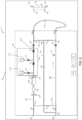
- the thermal disinfection system 1 comprises a dialysis apparatus 10 having a hydraulic circuit 100: the hydraulic circuit 100 comprises a feed arrangement 107a presenting at least one dialysis supply line 107 generally destined to transport a fluid, in particular water or purified water, from an inlet 101 towards an inlet 152 of a dialyzer 150 during a dialysis treatment.
- the hydraulic circuit 100 further comprises a return arrangement 171 having at least one dialysis effluent line 108, destined for the transport of a dialysate liquid (spent dialysate and/or liquid ultrafiltered from the blood through a semipermeable membrane 151 of the dialyzer 150) from an outlet 153 of the dialyzer 150 towards an exit, schematically denoted by 129 in figure 1 .
- a dialysate liquid spent dialysate and/or liquid ultrafiltered from the blood through a semipermeable membrane 151 of the dialyzer 150
- the hydraulic circuit 100 cooperates with a blood circuit (not represented).
- the specific structure of the blood circuit is not fundamental, with reference to the present invention. Thus, simply a brief description of a possible embodiment of a blood circuit is made, which is however provided purely by way of non-limiting example.
- the blood circuit comprises a blood withdrawal line 155 designed to remove blood from a vascular access and connected to an inlet of a primary chamber, or blood chamber, of the dialyzer 150.
- the blood circuit further comprises a blood return line 154 designed to return the treated blood to the vascular access and connected to an outlet 154 of the primary chamber of the dialyzer 150.
- the primary chamber of the dialyzer 150 communicates with the secondary chamber through the semipermeable membrane 151, for example made of hollow-fibre type or plate type.
- the dialysis supply line 107 is connected at the dialyzer treatment fluid inlet 152 of the secondary chamber, while the dialysis effluent line 108 is connected at the dialyzer treatment fluid outlet 153 of the secondary chamber.
- the blood circuit may also comprise one or more air separators, e.g. in the blood return line, upstream of a safety valve. Other air separators may be present in the blood circuit, such as positioned along the blood withdrawal line.
- the dialysis machine 1 may also comprise one or more blood pumps, for example positive displacement pumps such as peristaltic pumps, e.g. on the blood withdrawal line and optionally on the blood return line of the blood circuit.
- a flow pump 120 and a suction pump 122 may be included, located respectively on the dialysis fluid supply line 107 and on the dialysate effluent line 108 and also operatively connected to a control unit 500 of the dialysis machine 1.
- purified water enters into the feed arrangement at inlet 101.
- a heater 104 is also provided on the fluid supply line 107 and operatively connected to the control unit 500: when the inlet valve 102 is open, the heater 104 is configured to heat up the water during a blood treatment session, i.e.
- the heater 104 is configured to heat up the water during a disinfection procedure at higher temperatures T, i.e. with 65°C ⁇ T ⁇ 100°C.
- the heater may comprise an electric resistance configured to heat up due to electric current flow: the amount of heating energy or instant electric power provided by the heater 104 to the water may be set by controlling the amount of electric current flowing through the electric resistance.
- the control unit 500 may be configured to activate and deactivate the heater periodically to provide the water with a preset averaged heating energy.
- Purified and heated water may be collected into a tank 105 provided with an expansion tube 106 to allow gases, eventually dissolved in the liquid, to be released to the atmosphere.
- the apparatus also may also comprise a treatment fluid preparation unit 110 which may be of any known type, for example including one or more concentrate containers (A-concentrate 111 and B-concentrate 115) and respective concentrate pumps (A-pump 112 and B-pump 116) for the concentrate delivery, as well as at least a first and/or a second conductivity cell 114, 118.
- a treatment fluid preparation unit 110 which may be of any known type, for example including one or more concentrate containers (A-concentrate 111 and B-concentrate 115) and respective concentrate pumps (A-pump 112 and B-pump 116) for the concentrate delivery, as well as at least a first and/or a second conductivity cell 114, 118.
- Concentrate pump/s 112, 116 is/are arranged in the delivery line/s 112a, 116a in order to allow the metered mixing of water and concentrated solution in the dialysis supply line 107.
- the concentrate pump/s 112, 116 is/are driven on the basis of the comparison between 1) a target conductivity value for the mixture of liquids formed at respective infusion points where the dialysis supply line 107 joins the delivery line/s 112a, 116a, and 2) the value of the conductivity of this mixture measured by means of a respective conductivity sensor 114; 118 arranged in the dialysis supply line 107 downstream of the infusion point between the dialysis supply line 107 and the respective delivery line/s 112a, 116a.
- concentration sensor may be provided on the dialysis supply line 107.
- the first concentrate may be mixed with purified water in the dialysis supply line and the fluid conductivity measured immediately by the sensor 114 downstream the first infusion point.
- the second infusion point may be placed downstream the first conductivity sensor 114 and the second concentrate mixes with the fluid in the dialysis supply line.
- Conductivity or concentration of the prepared treatment fluid may be thereafter measured with the second conductivity sensor 118 before being directed to the dialyzer 150 during a blood treatment session.
- the dialysis fluid may contain, for example, ions of sodium, calcium, magnesium and potassium and the treatment fluid preparation unit 110 may be configured to prepare the dialysis fluid on the basis of a comparison between a target conductivity value and an actual conductivity value of the dialysis fluid measured by the conductivity sensors 114, 118.
- the concentrate pump/s 112, 116 is/are generally configured to control the concentration of specific ionic substances in the dialysis liquid. Generally it is advantageous to control the sodium and bicarbonate concentration of the dialysis fluid.
- only one conductivity sensor 118 may be used to control dialysis fluid preparation.
- the conductivity sensor 118 is placed on the feed arrangement downstream the infusion points of the first and second concentrate.
- other kinds of treatment fluid preparation unit 110 might be equivalently used, having a single or further concentrate sources and/or a single or more pumps.
- the treatment fluid preparation unit 110 may be any known system configured for on-line preparing dialysis fluid from water and concentrates.
- the hydraulic circuit 100 also comprises a supply fluid temperature sensor 127 operatively connected to the control unit 500 and configured to provide a signal representative of the water temperature within the circuit. Temperature check of the fluid is useful both during a standard blood treatment session and during a disinfection procedure of the fluid lines as described in more detail in the following description.
- the supply fluid temperature sensor 127 is arranged on the supply line 107. According to an embodiment, the temperature sensor 127 may be arranged downstream to the heater 104 to monitor the fluid outlet temperature.
- a second fluid supply temperature sensor 127' may also be provided on the supply line 107 and arranged upstream the heater 104.
- the treatment fluid outlet 130 of the dialysis supply line 107 may be connected to the fluid inlet 152 of the dialyzer 150 when treating a patient trough a treatment fluid removable connector 138.
- a disinfectant and/or a heated fluid are circulated in the dialysis supply line 107.
- the treatment fluid removable connector 138 of the dialysis supply line 107 is disconnected from the dialyzer 150 and is connected to a supply tube parking connector 136 provided in the chassis of the dialysis machine.
- a feed recirculation circuit 174 is designed to receive fluid from the supply tube parking connector 136 and to direct said fluid again to the feed arrangement 107a, in particular to the dialysis supply line 107 at a first connection point 140 immediately downstream the inlet valve 102 and upstream the heater 104.
- an auxiliary fluid loop path is defined allowing fluid re-circulation in said closed loop path including, at least a portion of, the feed arrangement 107a and the feed recirculation circuit 174.
- the supply line 107 is provided with the second fluid supply temperature sensor 127', the latter is interposed between the first connection point 140 and the inlet of the heater 104.
- water is fed through the inlet 101 and heated to the desired disinfection temperature by heater 104.
- the heater may be commanded by the control unit 500 to heat up water at a temperature comprised between 70°C and 100°C.
- the flow pump 120 operates continuously pumping the fluid in the auxiliary fluid loop path. Heated water passes along the feed arrangement 107a, the treatment fluid outlet 130, a treatment fluid supply tube 131, the supply tube parking connector 136 and the feed recirculation circuit 174 back to the feed arrangement 107a.
- heated water is re-circulated in the closed auxiliary fluid loop path for a predetermined time period sufficient to perform heat disinfection of the portion of the hydraulic circuit upstream the dialyzer 150.
- a first return valve 123 is placed in the feed recirculation circuit 174 for enabling and preventing, respectively, the circulation of fluid in the auxiliary fluid loop path.
- the first return valve 123 is open during thermal disinfection.
- disinfection efficiency during thermal disinfection procedure may be increased by using a disinfectant mixed with water: hot water mixed with a disinfectant solution determines an improvement in terms of disinfection and may allow to reduce the time required to reach a set disinfection threshold.
- the heater 104 may be arranged in the feed recirculation circuit 174 to heat water in the loop path. Additionally, a first heater may be provided on the supply line 107, as described before, and a second heater may be provided on the feed recirculation circuit 174.
- the hydraulic circuit 100 also comprises a return arrangement 171 arranged to remove the dialysis fluid from the dialyzer 150 during dialysis treatment and forward it to the exit 129.
- the dialysis effluent line 108 may be provided with a respective return fluid removable connector 139 configured to be removably connected to the fluid outlet 153 of the dialyzer 150 when treating a patient to receive dialysate fluid and directing it towards the exit 129.
- the exit is adapted for connection to a waste-bag or to a drain.
- a suction pump 122 and a second flow meter are disposed on the dialysis effluent line 108.
- the first and second flow meters may be used to control (in a known manner) the fluid balance of a patient connected to the blood circuit during a dialysis treatment session.
- a conductivity sensor may be provided on the dialysis effluent line 108, immediately downstream the dialyzer 150, to measure conductivity of the dialysate.
- a return fluid temperature sensor 128 is also arranged on the dialysis effluent line 108 to measure the temperature of the fluid circulating in the return arrangement 171: the return fluid temperature sensor 128 is preferably arranged downstream the suction pump 122.
- a first exit valve 125 is placed in the return arrangement 171 immediately upstream the exit 129 for enabling or preventing fluid of the return arrangement to be lead to the exit.
- heated fluid is circulated in the dialysis effluent line 108.
- the return fluid removable connector 139 of the dialysis effluent line 108 is disconnected from the dialyzer 150 and is connected to a return tube parking connector 137 provided in the chassis of the dialysis machine.
- a return recirculation circuit 173 is designed to receive fluid from the return tube parking connector 137 and to direct said fluid again to the return arrangement 171, in particular to the dialysis effluent line 108 at a fourth connection point 143 immediately upstream the exit 129 and preferably the first exit valve 125.
- a fluid loop path is defined allowing fluid re-circulation in a closed loop path including, at least a portion of, the return arrangement 171 and the return recirculation circuit 173.
- the fluid loop path is present to recirculate fluid, particularly during disinfection procedure; the auxiliary fluid loop path not being present in the 'clean side' of the hydraulic circuit.
- no feed recirculation circuit is provided.
- hot water heated to the desired disinfection temperature e.g. by heater 104, is fed to the fluid loop path through the feed arrangement 107a. For example water at a temperature of 70° - 100° degrees may be used.
- hot water may be provided via a by-pass line 109, shown in fig. 1 , or any other fluid connection between the dialysis supply line 107 (including the heater 104) and the fluid loop paths.
- an additional heater may be provided in the return arrangement 171 or in the return recirculation circuit 173, to heat water.
- a heat exchanger may be used to transfer heat from the fluid in the feed arrangement 107a to the fluid in the return arrangement 171 to reach the desired temperature of the fluid in the fluid loop path. Additional heater in the return arrangement may or may not be present.
- the control unit 500 commands the suction pump 122 to continuously pump the fluid in the fluid loop path.
- heated water passes through the return arrangement 171, the return recirculation circuit 173, the return tube parking connector 137, a treatment fluid return tube 132, a dialysate fluid return inlet 133, and back to the return arrangement 171.
- heated water is re-circulated in the closed fluid loop path for a predetermined time period sufficient to perform heat disinfection of the portion of the hydraulic circuit downstream the dialyzer 150.
- a second return valve 124 is placed in the return recirculation circuit 173 for enabling or preventing the circulation of fluid in the fluid loop path.
- the second return valve 124 is open during the thermal disinfection.
- disinfection of the fluid loop path may alternatively be obtained using a disinfectant mixed with water; disinfection may be achieved combined with heating of the disinfectant solution or not.
- the hydraulic circuit 100 according to figure 1 also includes a feed forward arrangement 172 arranged to enable a fluid of the feed arrangement 107a to be forwarded to a waste bag or drain by-passing the fluid loop path, i.e. by-passing the portion of the return arrangement 171 upstream the first exit valve 125 and by-passing the return recirculation circuit 173.
- the feed forward arrangement 172 is connected on one side to the dialysis supply line 107 or to the bypass line 109 and on the other side is directly connected to the exit 129 of the return arrangement 171.
- the feed forward arrangement 172 may be directly connected to the drain (or waste-bag) without being connected to the return arrangement 171.
- the feed forward arrangement 172 may, in some embodiments, have a discharge end portion independent and not directly connected to other lines of the hydraulic circuit and freely placeable.
- the feed forward arrangement 172 of figure 1 is connected to the auxiliary fluid loop path (in particular to the feed arrangement 107a) at a second connection point 141. Fluid from the auxiliary fluid loop path may be withdrawn at the second connection point 141 and directed to the exit 129 without circulating in the fluid loop path before being discharged.
- the feed forward arrangement 172 is connected to the return arrangement 171 at a sixth connecting point 145 placed downstream the fourth connecting point 143 where the return recirculation circuit 174 connects to the return arrangement 171.
- the feed forward arrangement 172 comprises a second exit valve 126 for enabling or preventing fluid of the feed arrangement to be lead to the exit through said feed forward arrangement.
- the hydraulic circuit 100 may also comprise the bypass line 109 which connects the dialysis fluid supply line 107 and the dialysate effluent line 108 bypassing the dialyzer 150, and one or more bypass valves 121 connected to the control unit 500 for selectively opening and closing the bypass line 109.
- the bypass valve 121 on command of the control unit opens; further the control unit 500 closes the fluid passage towards the treatment zone and connect the inlet 101 directly with the dialysis effluent line 108 through the bypass line 109.
- a first tract of the by-pass line 109 between the second connection point 141 and a fifth connection point 144 is in common with the feed forward arrangement 172.
- both bypass valve 121 and second exit valve 126 may be open at the same time whereby it is possible to direct fluid from the feed arrangement 107a both towards the return arrangement 171 and towards the exit 129.
- the by-pass line 109 is connected to the return arrangement 171 at a third connection point 142, upstream the suction pump 122.
- the hydraulic circuit 200 may comprise a shunt tube 132a directly connecting, during a thermal disinfection procedure, the treatment fluid outlet 130 of the supply line 107 with the dialysate fluid return inlet 133 of the dialysis effluent line 108.
- the hot water passes through the supply line 107, the shunt tube 132a, the effluent line 108 and towards the exit 129.
- the hydraulic circuit 100 may be provided with an auxiliary bypass line 109a connecting the effluent line 108, at a connecting point 147 upstream the exit 129, with the supply line 107 at the connecting point 140.
- the hot water passes through the supply line 107, the shunt tube 132a, the effluent line 108 and through the auxiliary bypass line 109a, defining a loop path for recirculating the hot water.
- the dialysis apparatus also comprise a pressure sensor 162 configured to provide a signal representative of the atmospheric pressure around the dialysis apparatus.
- the pressure sensor 162 is operatively connected to the control unit 500 which is configured to receive the representative pressure signal from the pressure sensor 162 and to provide in output an atmospheric pressure value.
- the apparatus may also comprise a user interface 501 (e.g. a graphic user interface or GUI) operatively connected to the control unit 500.
- the control unit 500 may, for example, comprise one or more digital microprocessor units or one or more analog units or other combinations of analog units and digital units. Relating by way of example to a microprocessor unit, once the unit has performed a special program (for example a program coming from outside or directly integrated on the microprocessor card), the unit is programmed, defining a plurality of functional blocks which constitute means each designed to perform respective operations.
- the control unit 500 of the dialysis apparatus 1 is connected to the (graphic) user interface 501 through which it may receive instructions, for example target values, such as a fluid set temperature T fluid_set , a threashold temperature TT, and a set disinfection dose A 0_set as described in more detail in the thermal disinfection procedure section.
- the (graphic) user interface 501 may also receive instructions to perform a treatment session, i.e. a blood treatment session: i.e. the user interface 501 may receive the blood flow rate Q b , dialysis fluid flow rate Q di , infusion liquid flow rate Q inf (where appropriate), patient weight loss WL.
- the control unit 500 furthermore may receive detected values by the sensors of the apparatus, such as the aforementioned flow meters, the conductivity sensors of treatment fluid preparation unit 110 and the conductivity sensor in the dialysis effluent line 108 and the first and second supply fluid temperature sensors 127, 127', and the return fluid temperature sensor 128.
- the control unit 500 drives the actuators of the apparatus, such as the blood pump, the aforementioned flow and suction pumps 120, 122, and the treatment fluid preparation unit 110 to perform a blood treatment session or to perform a disinfection procedure.
- the control unit 500 may also provide information to the user (e.g. treatment parameters and machine parameters) through the (graphic) user interface 501 about a thermal disinfection procedure of the hydraulic circuit 100 or the
- the thermal disinfection system 1 includes a water purification apparatus 300 fluidly connectable to one or more medical apparatuses, i.e. a peritoneal dialysis apparatus or to a blood treatment apparatus to provide purified water.
- a water purification apparatus 300 connectable to the medical apparatus (wherein the medical apparatus is not included), and a medical apparatus, in particular a peritoneal dialysis apparatus or the blood treatment apparatus 10 previously described, comprising the water purification apparatus 300.
- the water purification apparatus 300 may be fluidly connected to the inlet 101 of the blood treatment apparatus 10 previously described to provide purified water.
- the water purification apparatus 300 may be fluidly connected to a disposable set 40 (see figure 4 ) of a peritoneal dialysis apparatus.
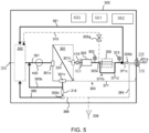
- a detailed description of the inner circuit of the water purification apparatus 300 is not fundamental for the purposes of the present invention: anyhow, an exemplary embodiment of a water purification apparatus 300, as shown in figures 3 and 5 , connectable to a peritoneal dialysis apparatus is described here after.
- the water purification apparatus 300 includes at least one between a pre-treatment module 160, a reverse-osmosis (RO) module 170 and a post-treatment module 180: fig. 3 shows an exemplary embodiment of the main functional parts of the water purification apparatus 300, including the pre-treatment module 160, the reverse-osmosis (RO) module 170 and the post-treatment module 180.
- the water purification apparatus 300 comprises an inlet port 399 for feeding water from a water source 398, e.g. a water tap, into the water purification apparatus 300, for purification of the water.
- a water source 398 e.g. a water tap
- the incoming water from the water source is fed through the inlet port 399 into the pre-treatment module 160.
- the Pre-treatment module 160 treats the incoming water with a particle filter and a bed of activated carbon.
- the particle filter is arranged to remove particles such as clay, silt and silicon from the incoming water.
- the particle filter is arranged to prohibit particles in the size of micro meter, optionally also larger endotoxin molecules, from the incoming water.
- the bed of activated carbon is arranged to remove chlorine and compositions with chlorine from the incoming water, and to absorb toxic substances and pesticides.
- the bed of activated carbon is arranged to remove one or several of hypochlorite, chloramine and chlorine.
- the bed of activated carbon is also arranged to reduce organic compounds (TOC total organic carbon) including pesticides of the incoming water.
- the particle filter and the bed of activated carbon are integrated in one single consumable part.
- the consumable part is for example exchanged on a predefined interval dependent on the incoming water quality.
- the quality of the incoming water is for example examined and determined by qualified people before the first use of the water purification apparatus 300 at a point of care.
- the pre-treatment module 160 comprises an ion exchange device for protection of downstream located devices such as a Reverse Osmosis, RO, membrane and a polisher.
- the pre-treatment module 160 thus filters the incoming water and delivers pre-treated water to a downstream located RO- module 170.
- RO-module The RO-module 170 removes impurities from the filtered water, such as microorganisms, pyrogens and ionic material from the pre-treated water by the effect of reverse osmosis.
- the pre-treated water is pressurized by a pump and forced through RO-membrane to overcome the osmotic pressure.
- the RO-membrane is for example a semi-permeable membrane.
- the stream of pre-treated water is divided into a reject stream of water and a stream of permeate water.
- the reject water may be passed via a one or both of a first reject path and a second reject path.
- the first reject path recirculates reject water back to the feed fluid path of the RO-pump in order to be fed back into RO-device again.
- the recirculated reject water increases the feed flow to the RO-device, to get a sufficient flow past the reject side of the RO-membrane to minimize scaling and fouling of the RO-membrane.
- the second reject path directs reject water to drain. This makes the concentration level on the reject side to be sufficiently low to get an appropriate, required, permeate fluid concentration. If the feed water has low content of solutes, part of the drain flow can also be directed back to the inlet side of the RO-membrane and thereby increasing the water efficiency of the water purification apparatus 300.
- the RO-module 170 thus treats the pre-treated water and delivers permeate water to a downstream located post-treatment module 180.
- Post-treatment module 180 polishes the permeate water in order to further remove ions from the permeate water.
- the permeate water is polished using a polisher device such as an Electrodeionization, EDI, device or a mixed bed filter device.
- the EDI-device makes use of electrodeionization for removing ions, from the permeate water, such as aluminum, lead, cadmium, chromium, sodium and/or potassium etc., which have penetrated the RO-membrane.
- the EDI-device utilizes electricity, ion exchange membranes and resin to deionize the permeate water and separate dissolved ions, i.e. impurities, from the permeate water.
- the EDI-device produce polished water, polished by the EDI-device to a higher purity level than the purity level of the permeate water.
- the EDI has an anti-bacterial effect of the product water and can reduce the amount of bacteria and endotoxins in the water due to, among other, the electrical field in the EDI-device.
- the mixed bed filter device comprises a column, or container, with a mixed bed ion exchange material.
- the purified water also called as product water, is thereafter ready for being delivered from a product port 328 of the water purification apparatus 300 to a point of use of the product water.
- the product water is suitable for dialysis, i.e. for blood dialysis or peritoneal dialysis.
- the product water may be used for injection in the blood stream of a patient.
- the water purification apparatus 300 comprises a drain port 318.
- the drain port 318 is in one example embodiment used for receiving used fluid, e.g. from a PD patient, via a drain line 64, for further transport via a first drain path 384 inside the water purification apparatus 300 to a drain 339 of the water purification apparatus 300.
- the drain port 318 receives a sample of ready mixed solution for further transport to a conductivity sensor arranged in the water purification apparatus 300, e.g. in the first drain path 384.
- a disposable line set 40 for peritoneal dialysis shown in figure 4 may be fluidly connected to the product port 328 of the water purification apparatus 300 to receive the purified water.
- Disposable set 40 includes an upstream water line segment 64a that extends to a water inlet 66a ( Fig. 2 ) of water an accumulator 66.
- a downstream water line segment 64b extends from a water outlet 66b ( Fig. 2 ) of the water accumulator 66 to a cassette 42.
- upstream water line segment 64a begins at a water line connector 68, which is located upstream from water accumulator 66, configured to be connected to the product port 328 of the water purification apparatus 300.
- Water purification apparatus 300 outputs purified water and water suitable for e.g. peritoneal dialysis ("WFPD").
- WFPD is water suitable for making dialysis fluid for delivery to the peritoneal cavity of a patient P.
- a sterile sterilizing grade filter 70a is placed upstream from a downstream sterile sterilizing grade filter 70b.
- Filters 70a and 70b may be placed in water line segment 64a upstream of the water accumulator 66.
- Sterile sterilizing grade filters 70a and 70b may be pass-through filters that do not have a reject line. Pore sizes for sterilizing filter may, for example, be less than a micron, such as 0.1 or 0.2 micron.
- Suitable sterile sterilizing grade filters 70a and 70b may, for example, be Pall IV-5 or GVS Speedflow filters, or be filters provided by the assignee of the present disclosure.
- only one or more than two sterile sterilizing grade filter are placed in water line segment 64a upstream of water accumulator 66.
- the one or several sterile sterilizing grade filters may be arranged close to the water accumulator 66, such that the fluid line set 40 becomes easier to fold.
- the sterile sterilizing grade filters may for example be replaced by one or several ultrafilters located in the product fluid path of the water purification apparatus 300.
- Disposable line set 40 includes a patient line 50 that extends from a patient line port of cassette 42 and terminates at a patient line connector 52 to be connected to the patient.
- Patient line connector 52 connects to a patient transfer set 54, which in turn connects to an indwelling catheter located in the peritoneal cavity of patient.
- Disposable line set 40 also includes a drain line 56 that extends from a drain line port of cassette 42 and terminates at a drain line connector 58. Drain line connector 58 may be connected removably to the drain port 318 of the water purification apparatus 300.
- Disposable set 40 further comprises a last bag or sample line 72 that extends from a last bag or sample port of cassette 42.
- Last bag or sample line 72 terminates at a connector 74, which may be connected to a mating connector of a premixed last fill bag of dialysis fluid or to a sample bag or other sample collecting container.
- Last bag or sample line 72 and connector 74 may be used alternatively for a third type of concentrate if desired.
- Disposable set 40 includes a first concentrate line 76 extending from a first concentrate port of the cassette 42 and terminates at a first cassette concentrate connector 80a.
- the first cassette concentrate connector 80a is configured to be fluidly connected to a first concentrate container 84a holding a first, e.g., glucose, concentrate.
- a second concentrate line 78 extends from a second concentrate port of cassette 42 and terminates at a second cassette concentrate connector 82a.
- the second container concentrate connector 82b is configured to be fluidly connected to a second concentrate container 84b holding a second, e.g., buffer, concentrate.
- patient P loads cassette 42 into a cycler and in a random or designated order (i) places heater/mixing bag 62 onto the cycler, (ii) connects upstream water line segment 64a to product port 328 of water purification apparatus 300, (iii) connects drain line 56 to drain port 318 of water purification apparatus 300, (iv) connects first cassette concentrate connector 80a to first container concentrate connector 80b, and (v) connects second cassette concentrate connector 82a to second container concentrate connector 82b.
- Fig. 5 illustrates a detailed embodiment of a water purification apparatus 300.
- the RO-device 301 is arranged to produce a purified fluid flow and a reject fluid flow.
- the RO-device 301 comprises a feed inlet 301a, a permeate outlet 301b and a reject outlet 301c.
- the RO-membrane 324 separates the feed inlet 301a and the reject outlet 301c, from the permeate outlet 301b.
- a feed fluid path 391 is connected to the feed inlet 301a, in order to transport feed fluid to the feed inlet 301a.
- the feed fluid path 391 is arranged with a tank 350 for collecting fluid, and a RO-pump 450, arranged to pump feed fluid to the feed inlet 301a.
- the RO-pump 450 is arranged downstream a tank 350.
- the RO-pump 450 is configured to be controlled by a control unit to a certain pump rate corresponding to a certain flow rate of the permeate fluid.
- the water purification apparatus 300 further comprises a purified fluid path 371, connected to the permeate outlet 301b and to the product port 328, in order to transport purified fluid from the permeate outlet 301b to the product port 328.
- the purified fluid path 371 comprises the permeate fluid path 371a, a polisher fluid path 371b and a product fluid path 371c.
- the polisher fluid path 371b comprises a polisher-device 306, for example an EDI-device or a mixed bed filter device.
- a bypass path 371d is arranged to bypass the polisher device.
- a three-way valve 305c is arranged to be controlled by the control unit 500 to direct the permeate fluid flow selectively to either into the polisher-device 306, or into the bypass path 371d in order to bypass the polisher-device 306.
- a first drain path 384 is connected to the drain port 318 and to the drain 339, in order to pass fluid from the drain port 318 to the drain 339.
- the first drain path 384 here embodies the part of a cycler drain path that is present inside the water purification apparatus 300.
- the first drain path is arranged for example to transport drained PD-solution from the patient to the drain 339 of the water purification apparatus 300.
- the water purification apparatus 300 is further arranged with a heating unit 302, also refereed as heater 302, arranged to heat the purified fluid produced by the RO-device 301 downstream the RO-device 301.
- the heater 302 may for example include a heating element.
- a first recirculation path 381, is arranged to circulate heated purified fluid from a point downstream the RO-device 301 and downstream the heater 302, to the feed fluid path 391, inside the water purification apparatus 300, upstream the pump 450 and the heater 302.
- the heated purified fluid is here recirculated to the tank 350 and again fed to the feed inlet 301a of the RO-device 301. However, the heated purified fluid is alternatively recirculated directly to the fluid line upstream the RO-pump 450.
- the reject flow is feed back to the feed fluid path 391 via a first reject path 385b.
- the first reject path 385b is connected with, and in fluid communication with, the reject outlet 301c and the feed fluid path 391.
- a second reject path 389 is connected with, and in fluid communication with, the reject outlet 301c of the tank 350. However, the second reject path 389 is alternatively connected with and in fluid communication with the feed fluid path 391.
- a second drain path 388 may be arranged to feed reject fluid from the reject outlet 301c to a drain 339.
- a valve 305b i.e. a three-way valve, is arranged to selectively direct the reject flow into either the second reject path 389 or into the second drain path 388.
- a constant flow device 318 is arranged to control the flow rate in the second reject path upstream the three-way valve 305b.
- the water purification apparatus 300 may comprise a second recirculation path 375 arranged with a flow control device 305a.
- the second recirculation path 375 is referred to as a second fluid path.
- the second recirculation path 375 is arranged to transport the heated purified fluid inside the water purification apparatus 300.
- the second drain path 388 is also referred to as a second fluid path.
- the control unit 500 is configured to perform a thermal disinfection procedure of the water purification apparatus 300. This means to control cleaning of all, or parts of, the parts of the fluid path of the RO module 170 and post-treatment module 180 of the water purification apparatus 300 that are in contact with fluid.
- a fluid path is here meant to include tubes, lines, channels inside of apparatuses, ports, the tank, components such as valves, control devices etc. of the water purification apparatus 300.
- the control unit 500 is configured to cause the water purification apparatus 300 to control heating, with the heater 302, of the purified fluid from the RO-device 301.
- the heater 302 comprises for example a heating rod.
- part of the permeate fluid path 371a is wound around the heating rod, in order to heat the purified fluid in the permeate fluid path 371a efficiently.
- the heater 302 comprises a heat exchanger, arranged to exchange heat between a heating medium and the fluid in permeate fluid path 371a.
- the heater 302 is in one embodiment configured to heat the purified fluid with a certain heating rate. By controlling the power to the heater 302, and thus the power of the heater, the heating rate of the heater 302 can be regulated. The heating rate is however also dependent on the flow rate of the purified fluid.
- a valve arrangement 305 is arranged to direct the heated purified fluid into the first fluid path or the second fluid path.
- the valve arrangement 305 comprises for example, but not limited to, one or several of: the flow control device 305a, the three-way valve 305b, a three-way valve 305c and a product water valve 305d.
- the water purification apparatus 300 comprises one or more temperature sensors 303, 313, 323.
- Temperature sensor 303 is arranged to measure a temperature of the water downstream the heater 302: in particular the temperature sensor 303 is arranged close to the outlet of the heater 302 so that the water temperature might be assumed as the maximum temperature of the water within the circuit.
- the temperature of the heated permeate indicates the temperature of the fluid in the first recirculation path 381.
- the temperature sensor 303 may also be called as high temperature sensor 303.
- a product fluid temperature sensor 313 may be arranged downstream the EDI-device 306 to measure the temperature of the water, thus the temperature of the fluid in the product fluid path 371c.
- a product fluid temperature sensor 323 may be arranged upstream the heating unit 302: in particular the temperature sensor 323 is arranged close to the inlet of the heating unit 302 so that the water temperature might be assumed as the lowest temperature of the water within the circuit.
- the temperature sensor 323 may also be called as low temperature sensor 323.
- a flow sensor 410 is arranged to measure a flow rate of the purified fluid.
- the flow sensor 410 is here arranged to the fluid path 371a and is arranged to measure the flow rate of the permeate fluid from the RO-device 301.
- the flow sensor 410 is arranged downstream the permeate outlet 301b, and upstream the heater 302, for example directly downstream the RO-device 301.
- control unit 500 is configured to control the valve arrangement 305 to re-circulate the heated purified fluid in a first fluid path, e.g. the first recirculation path 381, until a first temperature dependent criterion is fulfilled.
- the water purification apparatus 300 or the peritoneal dialysis apparatus also comprises the pressure sensor 362 configured to provide a signal representative of the atmospheric pressure around the dialysis apparatus.
- the pressure sensor 362 is operatively connected to the control unit 500 which is configured to receive the representative pressure signal from the pressure sensor 362 and to provide in output an atmospheric pressure value.
- the peritoneal dialysis apparatus of the above-described embodiment may also comprise a user interface 501 (e.g. a graphic user interface or GUI) operatively connected to the control unit 500 similar or equivalent to the user interface 501 of the blood treatment apparatus 10 previously described.
- the control unit 500 may, for example, comprise one or more digital microprocessor units or one or more analog units or other combinations of analog units and digital units.
- the unit Relating by way of example to a microprocessor unit, once the unit has performed a special program (for example a program coming from outside or directly integrated on the microprocessor card), the unit is programmed, defining a plurality of functional blocks which constitute means each designed to perform respective operations.
- a special program for example a program coming from outside or directly integrated on the microprocessor card
- the present invention is directed to a thermal disinfection system 1 configured to perform a disinfection procedure of the hydraulic circuit of the medical apparatus 10, such as a blood treatment apparatus 10 previously described.
- the thermal disinfection system 1 is configured to perform a disinfection procedure of the purifying water system 300, according to the above description, fluidly connectable to one or more medical apparatuses to provide water: this medical apparatus may be one or more blood treatment apparatuses 10 or a peritoneal dialysis apparatus for home use.
- the thermal disinfection system 1 is configured to perform a disinfection procedure of a peritoneal dialysis apparatus, in particular a disinfection procedure of fluid lines of a peritoneal dialysis apparatus, wherein the fluid lines may comprise disposable fluid lines or operational fluid lines internal to the peritoneal dialysis apparatus.
- the disinfection procedure comprises at least the steps of receiving a temperature signal from a temperature sensor 127, 127', 128; 303, 313 and determining a measured temperature value T fluid_mes of the fluid within the hydraulic circuit 100. Furthermore, the thermal disinfection procedure comprises the steps of receiving the pressure signal from the a pressure sensor 162; 362, determining a measured local atmospheric pressure value P atm , and driving the heating unit 104; 302 to heat up the fluid based on the measured temperature value T fluid_mes , and on the measured local atmospheric pressure value P atm .
- the thermal disinfection procedure also comprises determining a set temperature T fluid_set of the fluid based on the local atmospheric pressure value P atm , wherein this set temperature T fluid_set is comprised between 50°C and 105°C, in particular between 70°C and 100°C.
- the thermal disinfection procedure comprises controlling the heating unit 104; 302 based on the measured temperature value T fluid_mes , to heat up the fluid up to, and in particular not beyond, the set temperature T fluid_set .
- control unit 500 is configured to compare the measured temperature value T fluid_mes with the set temperature T fluid_set , compute a difference between the measured temperature value T fluid_mes with the set temperature T fluid_set , and based on this difference controlling the heating unit 104; 302 to heat up the fluid up to, and in particular not beyond, the set temperature T fluid_set .
- the local atmospheric pressure value P atm is related to the fluid set temperature T fluid_set by a predefined relationship: this relationship defines a boiling point temperature BPT as a function of the local atmospheric pressure value P atm .
- this relationship defines a boiling point temperature BPT as a function of the local atmospheric pressure value P atm .
- water at a local pressure of 1ATM has boiling point temperature BPT equal to 100°C: a decrease of the local temperature determines a decrease of the boiling point temperature BPT according to a well know relationship.
- the fluid set temperature T fluid_set may be comprised between limits as 0.9 ⁇ BPT ⁇ T fluid_set ⁇ BPT, more in particular 0.9 ⁇ BPT ⁇ T fluid_set ⁇ 0.99 ⁇ BPT, more in particular 0.93 ⁇ BPT ⁇ T fluid_set ⁇ 0.97 ⁇ BPT.
- the thermal disinfection procedure aims to maximize the fluid set temperature T fluid_set based on the local atmospheric pressure value P atm avoiding boiling of the fluid within the hydraulic circuit 100.
- the local pressure is 1ATM
- the fluid set temperature T fluid_set will be heated up as close as possible to 100°C: higher temperatures will be avoided in order to prevent boiling of the fluid within the hydraulic circuit 100 which may cause damage to the circuit itself or determine a poor disinfection efficiency.
- the thermal disinfection procedure may comprises a step of continuously updating measurements of the local atmospheric pressure P atm during the thermal disinfection procedure according to a predetermined sample rate comprised between 0,01Hz and 1000Hz, in particular comprised between 0,1Hz and 500Hz.
- the continuous updating may be periodic or random in time or based on a preset algorithm.
- the thermal disinfection procedure may comprises a step of continuously updating the set temperature T fluid_set during the disinfection procedure based on the updated measurements of the local atmospheric pressure P atm : in other terms, if the local atmospheric pressure P atm changes during the disinfection procedure, the set temperature T fluid_set will be changed accordingly. In this way, if the local atmospheric pressure P atm increases during the disinfection procedure, the set temperature T fluid_set will be increased as well, so that the time required to perform the disinfection procedure decreases as described here after in more detail.
- the thermal disinfection procedure may comprises a step of measuring the local atmospheric pressure P atm by the pressure sensor 162,362 only at an initial stage of the disinfection procedure or just before starting of the thermal disinfection procedure: therefore, the fluid set temperature T fluid_set is also set at the initial stage of the thermal disinfection procedure according to the measured local atmospheric pressure P atm , and kept constant during the whole thermal disinfection procedure. In this case, pressure fluctuations during the disinfection procedure are not taken into account and the set temperature T fluid_set does not change as well.
- the definition of the thermal disinfection process may be achieved through an "A 0" method which uses knowledge of the lethality of the particular process at different temperatures to assess the overall lethality of the cycle and express this as the equivalent exposure time at a specified temperature.
- A also referred as the disinfection dose, is defined as the equivalent time in seconds at 80°C which generates a certain disinfection action against microorganisms with a defined “z” value, where the "z” value is a measurement, expressed in °C, of the temperature relationship to the killing process.
- the "z” value corresponds to the increase in temperature required to reduce a "D" value of a particular microorganism by 90%: the “D” value is the time required at a given temperature to kill 90% of a population of the respective microorganisms (Decimal reduction time).
- the "z” value of a microorganism thus increases in tandem with growing resistance of this organism.
- a 0 ⁇ 10 T t ⁇ 80 / z ⁇ ⁇ t
- ⁇ t is the chosen time interval in seconds
- T is the fluid temperature in °C measured at the time "t”.
- a lower temperature limit for the integration is set at 65°C. Consequently, A 0 is a time related unit which is dependent on temperature.
- values of A 0 comprised between 600 and 3000 may be used: anyhow, lower or higher values of A 0 may be set according to the need.
- Fig. 6 shows the evolution of time, in minutes, required to complete a disinfection procedure as a function of the fluid temperature T fluid_set according to the equations 1 and 2, wherein the set disinfection dose A0_set is 600. The higher the fluid temperature, the lower is the time required for the disinfection procedure to be carried on.
- the thermal disinfection procedure further comprises the steps of receiving a set disinfection dose A 0_set representative of a disinfection grade required, and calculating, during the disinfection procedure, an achieved disinfection dose A 0_achieved .
- the disinfection procedure comprises comparing the achieved disinfection dose A 0_achieved with the set disinfection dose A 0_set and, based on this comparison, discontinue the disinfection procedure if the achieved disinfection dose A 0_achieved equals or exceeds the set disinfection dose A 0_set .
- the set disinfection dose A 0_set may be comprised between 40 and 2000, in particular between 200 and 1000, more in particular between 500 and 700.
- the calculating step of the achieved disinfection dose A 0_achieved is based on a reference fluid temperature T ref (namely the fluid temperature T in °C measured at the time "t" referred to in equations 1 and 2 reported above) measured by the at least one temperature sensor 127, 127', 128, wherein the reference fluid temperature T ref is assumed to be substantially the lowest fluid temperature within the hydraulic circuit 100 during the thermal disinfection procedure for safety reasons.
- T ref namely the fluid temperature T in °C measured at the time "t" referred to in equations 1 and 2 reported above
- the temperature sensor 127' may be also called as the low temperature sensor 127', wherein the latter is arranged upstream the heating unit 104 and close to the inlet of the heating unit 104: thus, the low temperature sensor 127' is configured to detect the reference fluid temperature T ref .
- the reference fluid temperature T ref may be measured by the return fluid temperature sensor 128, which is preferably arranged as close as possible to the drain exit 129, when the hydraulic circuit 100 is in an open configuration wherein the heated fluid flows from the inlet 101, through the dialysis supply line 107 and the dialysis effluent line 108, and towards the drain exit 129.
- a temperature sensor 323, also called as low temperature sensor 323, may be arranged upstream the heating unit 302.
- the control unit 500 is configured, during the disinfection procedure, to control heating power or energy provided by the heating unit 104, 302 to the fluid to reach the desired fluid temperature T fluid_set .
- the heating power is controlled by varying the electric energy provided.
- the disinfection procedure is completed when A 0_ achieved ⁇ A 0_ set corresponding to a disinfection procedure time period DPt: the disinfection procedure comprises step of storing in a memory, in particular a digital memory, this time period DPt relative to the completed disinfection procedure. Subsequently, the control unit 500 is configured to determine the starting time of a subsequent disinfection procedure based on this time period DPt of the preceding disinfection procedure.
- the thermal disinfection procedure may also comprise a step of receiving or storing a threshold temperature value TT, such that the step of the disinfection procedure of calculating the achieved disinfection dose A 0_achieved starts when a measured temperature of the heated fluid equals or exceeds said threshold temperature value TT: in particular this measured temperature of the heated fluid is the fluid reference temperature T ref .
- the achieved disinfection dose A 0_achieved is computed only based on time periods when the measured temperature of the fluid exceeds this threshold temperature value TT. On the contrary, during time periods wherein the measured temperature of the fluid is lower than this threshold temperature value TT, the achieved disinfection dose A 0_achieved is not computed. In other terms, the achieved disinfection dose A 0_achieved does not increment during time periods wherein the measured temperature of the fluid is lower than this threshold temperature value TT.
- FIG. 7 shows an exemplary heating curve of the fluid temperature within the hydraulic circuit 100 as a function of the elapsed time.
- C1 curve represents the initial fluid temperature (i.e. 60°C) before the disinfection procedure has started. Heating of the fluid starts at time t 0 , corresponding to the time when the control unit 500 activates the heating unit:
- C2 curve represents fluid temperature increase versus time, which occurs between t 0 and t 3 : in particular the fluid temperature curve C2 is preferably measured by the low temperature sensor of the hydraulic circuit and used to compute the achieved disinfection dose A 0_achieved .
- the fluid temperature of the curve C2 in figure 7 does not reach a flat constant maximum temperature, does not limit the present disclosure: indeed, during a thermal disinfection procedure the fluid measured temperature may definitely reach a plateau temperature (level C5) and maintained until the thermal disinfection procedure is completed.
- the plateau temperature is caused by the fact that the fluid maximum temperature at the outlet of the heating unit is controlled and maintained at a maximum fixed temperature T fluid_set .
- the curve C6 represents the threshold temperature value TT: when the fluid temperature curve C2 reaches the threshold temperature value TT at time t 1 , the disinfection procedure starts computing the achieved disinfection dose A 0_achieved . Calculation of the achieved disinfection dose A 0_achieved is performed between t 1 and t 3 . On the contrary, between t 0 and t 1 , the achieved disinfection dose A 0_achieved is not computed.
- the level C5 is the maximum temperature reached by the fluid at the low temperature sensor: indeed, the temperature detected at the high temperature sensor, namely at the outlet of the heating unit, may be higher than that represented by the curve C2.
- the curve C3 shows the fluid temperature decreasing which occurs when the thermal disinfection procedure is terminated, in particular when the control unit 500 deactivate the heating unit.
- the thermal disinfection procedure of the hydraulic circuit 100 further comprises activating the pump 120, 122; 450 during the thermal disinfection procedure to determine flowing of the heated fluid within the hydraulic circuit 100.
- the thermal disinfection procedure in order to exclude the dialyzer from the hydraulic circuit to be disinfected, may comprise a step of connecting a shunt tube 132a between the dialysis fluid supply outlet 130 and the dialysate fluid return inlet 133.
- the hydraulic circuit 100 may be configurable, at least during the disinfection procedure, in a loop circuit for recirculation of the heated fluid: according to the circuits previously described, the loop circuit may comprise the heating unit 104, the pump 120, 122, the at least one temperature sensor 127, 127', 128, at least part of the dialysis supply line 107, at least part of the dialysis effluent line 108, optionally one or more by-pass lines 109, 109a fluidly connecting the dialysis supply line 107 with the dialysis effluent line 108, and optionally the shunt tube 132a.
- the loop circuit may comprise the heating unit 104, the pump 120, 122, the at least one temperature sensor 127, 127', 128, at least part of the dialysis supply line 107, at least part of the dialysis effluent line 108, optionally one or more by-pass lines 109, 109a fluidly connecting the dialysis supply line 107 with the dialysis effluent line
- the disinfection procedure may imply to command, in an open or closed position, one or more valves 102, 121, 123, 124, 125, 126 of the dialysis apparatus to define this loop circuit for recirculation of the heated fluid.
- loop circuit it is meant a path wherein the same heated fluid circulates to perform the disinfection procedure.
- the control unit 500 may receive the local atmospheric pressure value P atm and based on the maximum temperature achievable without the fluid boiling into the lines determine which is the most efficient disinfection procedure among different disinfection procedures.
- control unit 500 may provide information to the user (e.g., through a user interface) about the disinfection procedure that takes the least time to perform. The user may select the proposed procedure or deny and continue with a different procedure.
- thermal disinfection procedure in more detail using the A 0 concept
- time to obtain the thermal disinfection may be too long and chemical disinfection could be preferred.
- the system may estimate the time needed to complete a thermal heat disinfection (based on fluid path design and empirical tests). The estimated time could be used as indication for the user when about to start heat disinfection. From this indication, the user may decide to continue with heat disinfection or choose another type of disinfection to save time between treatments. With a low temperature the heat disinfection may take a too long time to be considered as efficient and a chemical disinfection (with or without heat applied) could be a better choice.
- the control unit 500 based on the determined set temperature T fluid_set calculates an estimated time T est to completion of the thermal disinfection procedure; compares the estimated time T est to completion of the thermal disinfection procedure with a reference time; based on the comparison outcome, the control unit 500 continues with the thermal disinfection procedure or recommend (on the user interface) or starts a different disinfection procedure, such as a chemical disinfection procedure.
- the reference time may be the time required for a different (e.g., chemical) disinfection with regard to the thermal disinfection. Therefore, said different disinfection procedure requires less time for disinfection than thermal disinfection procedure.
- the different disinfection procedure is a chemical disinfection, using a chemical disinfection agent, such as NaOCl.
- another disinfection agent may be used, such as citric acid.
- the different disinfection procedure may also be based on heating a fluid that includes a chemical agent (i.e., it is a chemical and thermic disinfection); this is advantageous if reduces the disinfection time.
- a chemical agent i.e., it is a chemical and thermic disinfection
- control unit so that the different disinfection procedure may start automatically.
- the steps previously described of the thermal disinfection procedure may be performed by the control unit 500 of the blood treatment apparatus 10 or of the water purification apparatus 300 or of the peritoneal dialysis machine.
- the control unit may be arranged remotely, such as remote server, and configured to receive, through a wired or wireless transmitter, the input data from the sensor and to provide command signal to perform the procedure steps.
Landscapes
- Health & Medical Sciences (AREA)
- Heart & Thoracic Surgery (AREA)
- Urology & Nephrology (AREA)
- Life Sciences & Earth Sciences (AREA)
- Engineering & Computer Science (AREA)
- Animal Behavior & Ethology (AREA)
- Veterinary Medicine (AREA)
- Public Health (AREA)
- General Health & Medical Sciences (AREA)
- Emergency Medicine (AREA)
- Hematology (AREA)
- Vascular Medicine (AREA)
- Anesthesiology (AREA)
- Biomedical Technology (AREA)
- Environmental & Geological Engineering (AREA)
- Hydrology & Water Resources (AREA)
- Water Supply & Treatment (AREA)
- Chemical & Material Sciences (AREA)
- Organic Chemistry (AREA)
- Clinical Laboratory Science (AREA)
- External Artificial Organs (AREA)
- Apparatus For Disinfection Or Sterilisation (AREA)
Claims (15)
- Thermisches Desinfektionssystem (1) mit einer Blutbehandlungseinrichtung (10), umfassend einen Hydraulikkreislauf (100) für einen Fluiddurchgang, wobei der Hydraulikkreislauf (100) dies aufweist:- wenigstens eine Dialyseversorgungsleitung (107), die sich von einem Fluideinlass (101) zu einem Dialysefluidversorgungsauslass (130) erstreckt, der mit einem Einlass eines Dialysators (150) verbindbar ist;- eine Dialyseausflussleitung (108), die sich von einem Dialysatfluidrücklaufeinlass (133) zu einer Ablaufausgang (129) erstreckt, wobei der Dialysatfluidrücklaufeinlass (133) dazu ausgelegt ist, mit einem Auslass des Dialysators (150) verbunden zu werden;- eine Heizeinheit (104), die dazu ausgelegt ist, ein Fluid, insbesondere Wasser oder eine Desinfektionslösung oder ein Dialysefluid oder eine Mischung davon, in dem Hydraulikkreislauf (100) zu erhitzen;- wenigstens einen Temperatursensor (127, 127', 128), der dazu ausgelegt ist, ein Signal bereitzustellen, das eine Fluidtemperatur in dem Hydraulikkreislauf (100) darstellt;- wenigstens einen Drucksensor (162), der dazu ausgelegt ist, ein Signal bereitzustellen, das einen lokalen atmosphärischen Druck darstellt;wobei die Blutbehandlungseinrichtung (10) eine Steuereinheit (500) umfasst, die dazu ausgelegt ist, eine thermische Desinfektionsprozedur des Hydraulikkreislaufs (100) durchzuführen, wobei die thermische Desinfektionsprozedur wenigstens die folgenden, von der Steuereinheit (500) durchgeführten Schritte umfasst:- Empfangen des Temperatursignals von dem wenigstens einen Temperatursensor (127, 127', 128) und Bestimmen eines gemessenen Temperaturwertes (Tfluid_mes) des Fluids in dem Hydraulikkreislauf (100);- Empfangen des Drucksignals von dem wenigstens einen Drucksensor (162) und Bestimmen eines gemessenen lokalen atmosphärischen Druckwertes (Patm);- Bestimmen einer Einstelltemperatur (Tfluid_set) des Fluids, basierend auf dem lokalen atmosphärischen Druckwert (Patm), um ein Sieden des Fluids in dem Hydraulikkreislauf (100) zu vermeiden, wobei die Einstelltemperatur (Tfluid_set) zwischen 70° C und 105° C liegt;gekennzeichnet durch die Tatsache, dass die thermische Desinfektionsprozedur ferner wenigstens die folgenden, von der Steuereinheit (500) durchgeführten Schritte umfasst:- basierend auf der bestimmten Einstelltemperatur (Tfluid_set), Berechnen einer geschätzten Zeit (Test) bis zum Abschluss der thermischen Desinfektionsprozedur;- Vergleichen der geschätzten Zeit (Test) bis zum Abschluss der thermischen Desinfektionsprozedur mit einer Referenzzeit;- basierend auf einem Vergleichsergebnis, Fortsetzen der thermischen Desinfektionsprozedur oder Empfehlen/Starten einer anderen Desinfektionsprozedur, z. B. einer chemischen Desinfektionsprozedur.
- Thermisches Desinfektionssystem (1) nach Anspruch 1, wobei die andere Desinfektionsprozedur weniger Zeit zur Desinfektion erfordert als die thermische Desinfektionsprozedur, wobei es sich bei der anderen Desinfektionsprozedur insbesondere um eine chemische Desinfektion unter Verwendung eines chemischen Desinfektionsmittels wie etwa NaOCl handelt.
- Thermisches Desinfektionssystem (1) nach Anspruch 1 oder 2, wobei die Steuereinheit (500) dazu ausgelegt ist, an einer Benutzerschnittstelle der Blutbehandlungseinrichtung (10) eine Angabe bereitzustellen, dass die andere Desinfektionsprozedur empfohlen wird, und um einem Benutzer zu ermöglichen, die andere Desinfektionsprozedur zu akzeptieren oder zurückzuweisen.
- Thermisches Desinfektionssystem (1) nach einem der vorstehenden Ansprüche, wobei die Steuereinheit (500) dazu ausgelegt ist, die Heizeinheit (104) anzutreiben, um das Fluid basierend auf dem gemessenen Temperaturwert (Tfluid_mes) und dem gemessenen lokalen atmosphärischen Druckwert (Patm) zu erhitzen,
und wobei die Steuereinheit (500) ferner dazu ausgelegt ist, die Heizeinheit (104) basierend auf dem gemessenen Temperaturwert (Tfluid_mes) zu steuern, um das Fluid bis zu und insbesondere nicht über die Einstelltemperatur (Tfluid_set) hinausgehend zu erhitzen. - Thermisches Desinfektionssystem (1) nach einem der vorstehenden Ansprüche, wobei die Steuereinheit (500) dazu ausgelegt ist, die Fluideinstelltemperatur (Tfluid_set) basierend auf dem lokalen atmosphärischen Druckwert (Patm) zu maximieren, wobei ein Sieden des Fluids in dem Hydraulikkreislauf (100) vermieden wird.
- Thermisches Desinfektionssystem (1) nach einem der vorstehenden Ansprüche, wobei die Steuereinheit (500) ferner hierzu ausgelegt ist:- Empfangen einer einstellten Desinfektionsdosis A0-set, die einen erforderlichen Desinfektionsgrad darstellt;- Berechnen, während der Desinfektionsprozedur, einer erzielten Desinfektionsdosis A0_achieved,und wobei die Desinfektionsprozedur ferner ein Vergleichen der erzielten Desinfektionsdosis A0_achieved mit der eingestellten Desinfektionsdosis A0_set umfasst und, basierend auf dem Vergleich, das Aussetzen der Desinfektionsprozedur, falls die erzielte Desinfektionsdosis A0 achieved der eingestellten Desinfektionsdosis A0_set entspricht oder oder diese überschreitet.
- Thermisches Desinfektionssystem (1) nach dem vorstehenden Anspruch, wobei der Berechnungsschritt der erzielten Desinfektionsdosis (A0_achieved) auf einer Referenzfluidtemperatur (Tref) basiert, die von dem wenigstens einen Temperatursensor (127, 127', 128) gemessen wird, wobei angenommen wird, dass die Referenzfluidtemperatur (Tref) im Wesentlichen die niedrigste Fluidtemperatur in dem Hydraulikkreislauf (100) während der thermischen Desinfektionsprozedur ist.
- Thermisches Desinfektionssystem (1) nach einem der vorstehenden Ansprüche 6 und 7, wobei der Berechnungsschritt der erzielten Desinfektionsdosis A0_achieved eine Funktion der verstrichenen Zeit ist.
- Thermisches Desinfektionssystem (1) nach einem der vorstehenden Ansprüche 6-8, wobei die erzielte Desinfektionsdosis (A0_achieved) durch die folgende Desinfektionsdosis-Formel berechnet wird:

- Thermisches Desinfektionssystem (1) nach einem der vorstehenden Ansprüche 6-9, wobei die Desinfektionsprozedur abgeschlossen ist, wenn A0_achieved ≥ A 0_set einer Desinfektionsprozedur-Zeitperiode (DPt) entspricht, wobei die Steuereinheit (500) ferner dazu ausgelegt ist, in einem Speicher, insbesondere einem digitalen Speicher, die Zeitperiode (DPt) relativ zu der Desinfektionsprozedur zu speichern,
und wobei die Steuereinheit (500) eine Startzeit einer nachfolgenden Desinfektionsprozedur basierend auf der Zeitperiode (DPt) der vorhergehenden Desinfektionsprozedur bestimmt. - Thermisches Desinfektionssystem (1) nach einem der vorstehenden Ansprüche, wobei der Hydraulikkreislauf (100) einen Niedrigtemperatursensor (127'; 323) des wenigstens einen Temperatursensors (127, 127', 128; 303, 313, 323) umfasst, der stromaufwärts der Heizeinheit (104) angeordnet ist, wobei der Niedrigtemperatursensor (127'; 323) insbesondere in der Nähe des Einlasses der Heizeinheit (104; 302), insbesondere an der Dialyseversorgungsleitung (107), angeordnet ist.
- Thermisches Desinfektionssystem (1) nach den vorstehenden Ansprüchen 9 und 11, wobei angenommen wird, dass die Fluidtemperatur, die von dem Niedrigtemperatursensor (127'; 323) gemessen wird, im Wesentlichen die niedrigste Fluidtemperatur in dem Hydraulikkreislauf (100) ist, und wobei, falls das Fluid in einem Schleifenkreislauf fließt, die von dem Niedrigtemperatursensor (127'; 323) gemessene Fluidtemperatur die Referenztemperatur (Tref) der Desinfektionsdosis-Formel ist.
- Thermisches Desinfektionssystem (1) nach Anspruch 9 und gemäß einem der vorstehenden Ansprüche, wobei der Hydraulikkreislauf (100) einen Rücklauffluidtemperatursensor (128) des wenigstens einen Temperatursensors (127, 127', 128) umfasst, der an der Dialyseausflussleitung (108) angeordnet ist, wobei der Rücklauffluidtemperatursensor (128) optional so nah wie möglich an dem Ablaufausgang (129) angeordnet ist, vorzugsweise stromabwärts einer Rücklauffluidpumpe (122), die an der Dialyseausflussleitung (108) angeordnet ist,
wobei die Fluidtemperatur, die von dem Rücklauffluidtemperatursensor (128) gemessen wird, die Referenztemperatur (Tref) der Desinfektionsdosisformel ist, wenn der Hydraulikkreislauf (100) in einer offenen Konfiguration vorliegt, wobei das erhitzte Fluid von dem Einlass (101) durch die Dialyseversorgungsleitung (107) und die Dialyseausflussleitung (108) in Richtung des Ablaufausgangs (129) fließt. - Thermisches Desinfektionssystem (1) nach einem der vorstehenden Ansprüche, wobei der Hydraulikkreislauf (100) einen Hochtemperatursensor (127; 303) des wenigstens einen Temperatursensors (127, 127', 128; 303, 313, 323) umfasst, der stromabwärts der Heizeinheit (104; 302) angeordnet ist, wobei der Hochtemperatursensor (127; 303) insbesondere in der Nähe des Auslasses der Heizeinheit (104; 302), insbesondere an der Dialyseversorgungsleitung (107), angeordnet ist,
wobei der Hochtemperatursensor (127; 303) dazu ausgelegt ist, den Fluidtemperaturwert (Tfluid_mes) des Fluids zu detektieren, wobei die Steuereinheit (500) dazu ausgelegt ist, die Heizeinheit (104; 302) so zu steuern, dass Tfluid_mes=Tfluid_set ist. - Thermisches Desinfektionssystem (1) nach einem der vorstehenden Ansprüche, wobei der Hydraulikkreislauf (100), wenigstens während der Desinfektionsprozedur, in einem Schleifenkreislauf zur Rezirkulation des erhitzten Fluids konfigurierbar ist, wobei der Schleifenkreislauf wenigstens die Heizeinheit (104), die wenigstens eine Pumpe (120, 122; 450), den wenigstens einen Temperatursensor (127, 127', 128; 303, 313, 323), wenigstens einen Teil der Dialyseversorgungsleitung (107), wenigstens einen TEil der Dialyseausflussleitung (108), optional eine oder mehrere Umgehungsleitungen (109, 109a), die eine Fluidverbindung der Dialyseversorgungsleitung (107) mit der Dialyseausflussleitung (108) herstellen, optional eine Shunt-Röhre (132a) umfasst und wobei der Hydraulikkreislauf (100) ein oder mehrere Ventile (102, 121, 123, 124, 125, 126) umfasst, die zwischen einer offenen und einer geschlossenen Position durch die Steuereinheit (500) steuerbar sind, um den Fluiddurchgang zu erlauben bzw. zu verhindern,
wobei die Steuereinheit (500) ferner dazu ausgelegt ist, die ein oder mehreren Ventile (102, 121, 123, 124, 125, 126) zu steuern, um den Schleifenkreislauf für eine Rezirkulation des erhitzten Fluids zu definieren.
Priority Applications (1)
| Application Number | Priority Date | Filing Date | Title |
|---|---|---|---|
| EP25174913.1A EP4574776A3 (de) | 2020-07-09 | 2021-07-06 | Thermisches desinfektionssystem für ein medizinisches gerät |
Applications Claiming Priority (2)
| Application Number | Priority Date | Filing Date | Title |
|---|---|---|---|
| IT102020000016756A IT202000016756A1 (it) | 2020-07-09 | 2020-07-09 | Sistema di disinfezione termica per un apparecchio medico |
| PCT/EP2021/068590 WO2022008481A1 (en) | 2020-07-09 | 2021-07-06 | Thermal disinfection system for a medical apparatus |
Related Child Applications (1)
| Application Number | Title | Priority Date | Filing Date |
|---|---|---|---|
| EP25174913.1A Division EP4574776A3 (de) | 2020-07-09 | 2021-07-06 | Thermisches desinfektionssystem für ein medizinisches gerät |
Publications (2)
| Publication Number | Publication Date |
|---|---|
| EP4178641A1 EP4178641A1 (de) | 2023-05-17 |
| EP4178641B1 true EP4178641B1 (de) | 2025-06-04 |
Family
ID=72473911
Family Applications (2)
| Application Number | Title | Priority Date | Filing Date |
|---|---|---|---|
| EP25174913.1A Pending EP4574776A3 (de) | 2020-07-09 | 2021-07-06 | Thermisches desinfektionssystem für ein medizinisches gerät |
| EP21739681.1A Active EP4178641B1 (de) | 2020-07-09 | 2021-07-06 | Thermisches desinfektionssystem für ein medizinisches gerät |
Family Applications Before (1)
| Application Number | Title | Priority Date | Filing Date |
|---|---|---|---|
| EP25174913.1A Pending EP4574776A3 (de) | 2020-07-09 | 2021-07-06 | Thermisches desinfektionssystem für ein medizinisches gerät |
Country Status (7)
| Country | Link |
|---|---|
| US (1) | US12611494B2 (de) |
| EP (2) | EP4574776A3 (de) |
| JP (1) | JP7667244B2 (de) |
| CN (2) | CN119792686A (de) |
| BR (1) | BR112023000391A2 (de) |
| IT (1) | IT202000016756A1 (de) |
| WO (1) | WO2022008481A1 (de) |
Families Citing this family (4)
| Publication number | Priority date | Publication date | Assignee | Title |
|---|---|---|---|---|
| CN114812848A (zh) * | 2022-05-17 | 2022-07-29 | 苏州立洗嘉医疗科技有限公司 | 一种适用于清洗消毒机用a0值及温度显示的监测方法 |
| DE102022123274A1 (de) * | 2022-09-13 | 2024-03-14 | B.Braun Avitum Ag | Verfahren zum Desinfizieren einer medizinischen Vorrichtung und medizinische Vorrichtung |
| DE102023118782A1 (de) * | 2023-07-16 | 2025-01-16 | Fresenius Medical Care Deutschland Gmbh | Extrakorporale blutbehandlungsvorrichtung und verfahren zur überprüfung einer extrakorporalen blutbehandlungsvorrichtung |
| DE102024103544A1 (de) | 2024-02-08 | 2025-08-14 | B.Braun Avitum Ag | System und Verfahren zur thermischen Desinfektion einer Umkehrosmoseanlage |
Family Cites Families (9)
| Publication number | Priority date | Publication date | Assignee | Title |
|---|---|---|---|---|
| SE510026C2 (sv) * | 1994-09-23 | 1999-04-12 | Gambro Ab | Desinficeringsanordning för dialysmaskin |
| US5591344A (en) * | 1995-02-13 | 1997-01-07 | Aksys, Ltd. | Hot water disinfection of dialysis machines, including the extracorporeal circuit thereof |
| US8409441B2 (en) | 2007-02-27 | 2013-04-02 | Deka Products Limited Partnership | Blood treatment systems and methods |
| CN103813816B (zh) | 2011-06-01 | 2016-04-27 | 弗雷塞尼斯医疗保健控股公司 | 用于透析机入口线路的集中热消毒的入口温度监视的方法和系统 |
| AU2013201567B2 (en) * | 2012-11-28 | 2015-12-17 | Gambro Lundia Ab | Systems, apparatus, equipment with thermal disinfection and thermal disinfection methods |
| CN106110350B (zh) * | 2016-06-28 | 2019-03-05 | 广东宝莱特医用科技股份有限公司 | 一种高原地区血液透析机消毒自动控制方法 |
| DE102016117600A1 (de) | 2016-09-19 | 2018-03-22 | B. Braun Avitum Ag | Verfahren zum Desinfizieren eines Hydrauliksystems einer Vorrichtung zur extrakorporalen Blutbehandlung mittels Heißdesinfektion sowie derartige Vorrichtung |
| US10376843B2 (en) | 2017-01-20 | 2019-08-13 | Fresenius Medical Care Holdings, Inc. | Method of detecting a leak in a heat exchanger of a hemodialysis machine |
| EP3618887B1 (de) * | 2017-05-05 | 2025-07-23 | Baxter International Inc. | System und verfahren zur herstellung eines mikrobiologisch gesteuerten fluids |
-
2020
- 2020-07-09 IT IT102020000016756A patent/IT202000016756A1/it unknown
-
2021
- 2021-07-06 JP JP2023501286A patent/JP7667244B2/ja active Active
- 2021-07-06 CN CN202411982729.3A patent/CN119792686A/zh active Pending
- 2021-07-06 US US18/014,978 patent/US12611494B2/en active Active
- 2021-07-06 EP EP25174913.1A patent/EP4574776A3/de active Pending
- 2021-07-06 BR BR112023000391A patent/BR112023000391A2/pt unknown
- 2021-07-06 EP EP21739681.1A patent/EP4178641B1/de active Active
- 2021-07-06 WO PCT/EP2021/068590 patent/WO2022008481A1/en not_active Ceased
- 2021-07-06 CN CN202180062068.0A patent/CN116057016B/zh active Active
Also Published As
| Publication number | Publication date |
|---|---|
| CN119792686A (zh) | 2025-04-11 |
| JP2023532804A (ja) | 2023-07-31 |
| JP7667244B2 (ja) | 2025-04-22 |
| US20230256150A1 (en) | 2023-08-17 |
| WO2022008481A1 (en) | 2022-01-13 |
| BR112023000391A2 (pt) | 2023-01-31 |
| EP4178641A1 (de) | 2023-05-17 |
| IT202000016756A1 (it) | 2022-01-09 |
| CN116057016A (zh) | 2023-05-02 |
| US12611494B2 (en) | 2026-04-28 |
| CN116057016B (zh) | 2025-01-17 |
| EP4574776A3 (de) | 2025-07-23 |
| EP4574776A2 (de) | 2025-06-25 |
Similar Documents
| Publication | Publication Date | Title |
|---|---|---|
| US12134076B2 (en) | Water purification apparatus and methods for cleaning the water purification apparatus | |
| EP4178641B1 (de) | Thermisches desinfektionssystem für ein medizinisches gerät | |
| JP7418039B2 (ja) | 浄水装置および浄水装置における少なくとも1つの流体特性を制御する方法 | |
| US6254567B1 (en) | Flow-through peritoneal dialysis systems and methods with on-line dialysis solution regeneration | |
| US20230202896A9 (en) | A system and a method for producing microbiologically controlled fluid | |
| JP2002000012U (ja) | 連続的腹膜透析法を実施するシステム | |
| US20260034289A1 (en) | System and method for producing fluid for peritoneal dialysis | |
| US11890401B2 (en) | Dialysis machines and methods of disinfecting a dialysis machine | |
| EP4175692B1 (de) | Dialysesystem | |
| US20240424180A1 (en) | Peritoneal dialysis cycler using sorbent | |
| US20240189777A1 (en) | Water purification apparatus and methods for cleaning the water purification apparatus | |
| WO2025176646A1 (en) | A water purification apparatus and methods for cleaning the water purification apparatus |
Legal Events
| Date | Code | Title | Description |
|---|---|---|---|
| STAA | Information on the status of an ep patent application or granted ep patent |
Free format text: STATUS: UNKNOWN |
|
| STAA | Information on the status of an ep patent application or granted ep patent |
Free format text: STATUS: THE INTERNATIONAL PUBLICATION HAS BEEN MADE |
|
| PUAI | Public reference made under article 153(3) epc to a published international application that has entered the european phase |
Free format text: ORIGINAL CODE: 0009012 |
|
| STAA | Information on the status of an ep patent application or granted ep patent |
Free format text: STATUS: REQUEST FOR EXAMINATION WAS MADE |
|
| 17P | Request for examination filed |
Effective date: 20221221 |
|
| AK | Designated contracting states |
Kind code of ref document: A1 Designated state(s): AL AT BE BG CH CY CZ DE DK EE ES FI FR GB GR HR HU IE IS IT LI LT LU LV MC MK MT NL NO PL PT RO RS SE SI SK SM TR |
|
| DAV | Request for validation of the european patent (deleted) | ||
| DAX | Request for extension of the european patent (deleted) | ||
| GRAP | Despatch of communication of intention to grant a patent |
Free format text: ORIGINAL CODE: EPIDOSNIGR1 |
|
| STAA | Information on the status of an ep patent application or granted ep patent |
Free format text: STATUS: GRANT OF PATENT IS INTENDED |
|
| RIC1 | Information provided on ipc code assigned before grant |
Ipc: C02F 9/20 20230101ALI20250106BHEP Ipc: A61M 1/28 20060101ALI20250106BHEP Ipc: C02F 1/02 20230101ALI20250106BHEP Ipc: A61M 1/16 20060101AFI20250106BHEP |
|
| INTG | Intention to grant announced |
Effective date: 20250123 |
|
| RIN1 | Information on inventor provided before grant (corrected) |
Inventor name: LUNSJO, JAN Inventor name: PERSSON, PATRIK |
|
| GRAS | Grant fee paid |
Free format text: ORIGINAL CODE: EPIDOSNIGR3 |
|
| GRAA | (expected) grant |
Free format text: ORIGINAL CODE: 0009210 |
|
| STAA | Information on the status of an ep patent application or granted ep patent |
Free format text: STATUS: THE PATENT HAS BEEN GRANTED |
|
| AK | Designated contracting states |
Kind code of ref document: B1 Designated state(s): AL AT BE BG CH CY CZ DE DK EE ES FI FR GB GR HR HU IE IS IT LI LT LU LV MC MK MT NL NO PL PT RO RS SE SI SK SM TR |
|
| REG | Reference to a national code |
Ref country code: GB Ref legal event code: FG4D |
|
| REG | Reference to a national code |
Ref country code: CH Ref legal event code: EP |
|
| REG | Reference to a national code |
Ref country code: DE Ref legal event code: R096 Ref document number: 602021031796 Country of ref document: DE |
|
| REG | Reference to a national code |
Ref country code: IE Ref legal event code: FG4D |
|
| REG | Reference to a national code |
Ref country code: NL Ref legal event code: MP Effective date: 20250604 |
|
| PG25 | Lapsed in a contracting state [announced via postgrant information from national office to epo] |
Ref country code: FI Free format text: LAPSE BECAUSE OF FAILURE TO SUBMIT A TRANSLATION OF THE DESCRIPTION OR TO PAY THE FEE WITHIN THE PRESCRIBED TIME-LIMIT Effective date: 20250604 Ref country code: ES Free format text: LAPSE BECAUSE OF FAILURE TO SUBMIT A TRANSLATION OF THE DESCRIPTION OR TO PAY THE FEE WITHIN THE PRESCRIBED TIME-LIMIT Effective date: 20250604 |
|
| PGFP | Annual fee paid to national office [announced via postgrant information from national office to epo] |
Ref country code: DE Payment date: 20250620 Year of fee payment: 5 |
|
| REG | Reference to a national code |
Ref country code: LT Ref legal event code: MG9D |
|
| PG25 | Lapsed in a contracting state [announced via postgrant information from national office to epo] |
Ref country code: NO Free format text: LAPSE BECAUSE OF FAILURE TO SUBMIT A TRANSLATION OF THE DESCRIPTION OR TO PAY THE FEE WITHIN THE PRESCRIBED TIME-LIMIT Effective date: 20250904 Ref country code: GR Free format text: LAPSE BECAUSE OF FAILURE TO SUBMIT A TRANSLATION OF THE DESCRIPTION OR TO PAY THE FEE WITHIN THE PRESCRIBED TIME-LIMIT Effective date: 20250905 |
|
| PG25 | Lapsed in a contracting state [announced via postgrant information from national office to epo] |
Ref country code: PL Free format text: LAPSE BECAUSE OF FAILURE TO SUBMIT A TRANSLATION OF THE DESCRIPTION OR TO PAY THE FEE WITHIN THE PRESCRIBED TIME-LIMIT Effective date: 20250604 |
|
| PG25 | Lapsed in a contracting state [announced via postgrant information from national office to epo] |
Ref country code: BG Free format text: LAPSE BECAUSE OF FAILURE TO SUBMIT A TRANSLATION OF THE DESCRIPTION OR TO PAY THE FEE WITHIN THE PRESCRIBED TIME-LIMIT Effective date: 20250604 |
|
| PGFP | Annual fee paid to national office [announced via postgrant information from national office to epo] |
Ref country code: GB Payment date: 20250725 Year of fee payment: 5 |
|
| PG25 | Lapsed in a contracting state [announced via postgrant information from national office to epo] |
Ref country code: HR Free format text: LAPSE BECAUSE OF FAILURE TO SUBMIT A TRANSLATION OF THE DESCRIPTION OR TO PAY THE FEE WITHIN THE PRESCRIBED TIME-LIMIT Effective date: 20250604 |
|
| PGFP | Annual fee paid to national office [announced via postgrant information from national office to epo] |
Ref country code: AT Payment date: 20251020 Year of fee payment: 5 Ref country code: FR Payment date: 20250723 Year of fee payment: 5 |
|
| PG25 | Lapsed in a contracting state [announced via postgrant information from national office to epo] |
Ref country code: RS Free format text: LAPSE BECAUSE OF FAILURE TO SUBMIT A TRANSLATION OF THE DESCRIPTION OR TO PAY THE FEE WITHIN THE PRESCRIBED TIME-LIMIT Effective date: 20250904 |
|
| PG25 | Lapsed in a contracting state [announced via postgrant information from national office to epo] |
Ref country code: LV Free format text: LAPSE BECAUSE OF FAILURE TO SUBMIT A TRANSLATION OF THE DESCRIPTION OR TO PAY THE FEE WITHIN THE PRESCRIBED TIME-LIMIT Effective date: 20250604 |
|
| PG25 | Lapsed in a contracting state [announced via postgrant information from national office to epo] |
Ref country code: NL Free format text: LAPSE BECAUSE OF FAILURE TO SUBMIT A TRANSLATION OF THE DESCRIPTION OR TO PAY THE FEE WITHIN THE PRESCRIBED TIME-LIMIT Effective date: 20250604 |
|
| PG25 | Lapsed in a contracting state [announced via postgrant information from national office to epo] |
Ref country code: PT Free format text: LAPSE BECAUSE OF FAILURE TO SUBMIT A TRANSLATION OF THE DESCRIPTION OR TO PAY THE FEE WITHIN THE PRESCRIBED TIME-LIMIT Effective date: 20251006 |
|
| REG | Reference to a national code |
Ref country code: AT Ref legal event code: MK05 Ref document number: 1799760 Country of ref document: AT Kind code of ref document: T Effective date: 20250604 |
|
| PG25 | Lapsed in a contracting state [announced via postgrant information from national office to epo] |
Ref country code: IS Free format text: LAPSE BECAUSE OF FAILURE TO SUBMIT A TRANSLATION OF THE DESCRIPTION OR TO PAY THE FEE WITHIN THE PRESCRIBED TIME-LIMIT Effective date: 20251004 |
|
| PG25 | Lapsed in a contracting state [announced via postgrant information from national office to epo] |
Ref country code: AT Free format text: LAPSE BECAUSE OF FAILURE TO SUBMIT A TRANSLATION OF THE DESCRIPTION OR TO PAY THE FEE WITHIN THE PRESCRIBED TIME-LIMIT Effective date: 20250604 Ref country code: SM Free format text: LAPSE BECAUSE OF FAILURE TO SUBMIT A TRANSLATION OF THE DESCRIPTION OR TO PAY THE FEE WITHIN THE PRESCRIBED TIME-LIMIT Effective date: 20250604 |
|
| PG25 | Lapsed in a contracting state [announced via postgrant information from national office to epo] |
Ref country code: CZ Free format text: LAPSE BECAUSE OF FAILURE TO SUBMIT A TRANSLATION OF THE DESCRIPTION OR TO PAY THE FEE WITHIN THE PRESCRIBED TIME-LIMIT Effective date: 20250604 |
|
| PG25 | Lapsed in a contracting state [announced via postgrant information from national office to epo] |
Ref country code: EE Free format text: LAPSE BECAUSE OF FAILURE TO SUBMIT A TRANSLATION OF THE DESCRIPTION OR TO PAY THE FEE WITHIN THE PRESCRIBED TIME-LIMIT Effective date: 20250604 |
|
| PG25 | Lapsed in a contracting state [announced via postgrant information from national office to epo] |
Ref country code: SK Free format text: LAPSE BECAUSE OF FAILURE TO SUBMIT A TRANSLATION OF THE DESCRIPTION OR TO PAY THE FEE WITHIN THE PRESCRIBED TIME-LIMIT Effective date: 20250604 |
|
| PG25 | Lapsed in a contracting state [announced via postgrant information from national office to epo] |
Ref country code: IT Free format text: LAPSE BECAUSE OF FAILURE TO SUBMIT A TRANSLATION OF THE DESCRIPTION OR TO PAY THE FEE WITHIN THE PRESCRIBED TIME-LIMIT Effective date: 20250604 |
|
| REG | Reference to a national code |
Ref country code: CH Ref legal event code: H13 Free format text: ST27 STATUS EVENT CODE: U-0-0-H10-H13 (AS PROVIDED BY THE NATIONAL OFFICE) Effective date: 20260224 |
|
| REG | Reference to a national code |
Ref country code: DE Ref legal event code: R097 Ref document number: 602021031796 Country of ref document: DE |
|
| PG25 | Lapsed in a contracting state [announced via postgrant information from national office to epo] |
Ref country code: RO Free format text: LAPSE BECAUSE OF FAILURE TO SUBMIT A TRANSLATION OF THE DESCRIPTION OR TO PAY THE FEE WITHIN THE PRESCRIBED TIME-LIMIT Effective date: 20250604 |
|
| PG25 | Lapsed in a contracting state [announced via postgrant information from national office to epo] |
Ref country code: LU Free format text: LAPSE BECAUSE OF NON-PAYMENT OF DUE FEES Effective date: 20250706 |
|
| REG | Reference to a national code |
Ref country code: BE Ref legal event code: MM Effective date: 20250731 |
|
| PG25 | Lapsed in a contracting state [announced via postgrant information from national office to epo] |
Ref country code: MC Free format text: LAPSE BECAUSE OF FAILURE TO SUBMIT A TRANSLATION OF THE DESCRIPTION OR TO PAY THE FEE WITHIN THE PRESCRIBED TIME-LIMIT Effective date: 20250604 |
|
| PLBE | No opposition filed within time limit |
Free format text: ORIGINAL CODE: 0009261 |
|
| STAA | Information on the status of an ep patent application or granted ep patent |
Free format text: STATUS: NO OPPOSITION FILED WITHIN TIME LIMIT |
|
| PG25 | Lapsed in a contracting state [announced via postgrant information from national office to epo] |
Ref country code: DK Free format text: LAPSE BECAUSE OF FAILURE TO SUBMIT A TRANSLATION OF THE DESCRIPTION OR TO PAY THE FEE WITHIN THE PRESCRIBED TIME-LIMIT Effective date: 20250604 |
|
| PG25 | Lapsed in a contracting state [announced via postgrant information from national office to epo] |
Ref country code: BE Free format text: LAPSE BECAUSE OF NON-PAYMENT OF DUE FEES Effective date: 20250731 |
|
| REG | Reference to a national code |
Ref country code: CH Ref legal event code: L10 Free format text: ST27 STATUS EVENT CODE: U-0-0-L10-L00 (AS PROVIDED BY THE NATIONAL OFFICE) Effective date: 20260416 |
|
| PG25 | Lapsed in a contracting state [announced via postgrant information from national office to epo] |
Ref country code: CH Free format text: LAPSE BECAUSE OF NON-PAYMENT OF DUE FEES Effective date: 20250731 |