EP4178518B1 - Rehabilitationsexoskelettvorrichtung mit einem unteren teil und steuerungsverfahren - Google Patents
Rehabilitationsexoskelettvorrichtung mit einem unteren teil und steuerungsverfahren Download PDFInfo
- Publication number
- EP4178518B1 EP4178518B1 EP21842004.0A EP21842004A EP4178518B1 EP 4178518 B1 EP4178518 B1 EP 4178518B1 EP 21842004 A EP21842004 A EP 21842004A EP 4178518 B1 EP4178518 B1 EP 4178518B1
- Authority
- EP
- European Patent Office
- Prior art keywords
- limb
- intact
- joint
- paralytic
- paretic
- Prior art date
- Legal status (The legal status is an assumption and is not a legal conclusion. Google has not performed a legal analysis and makes no representation as to the accuracy of the status listed.)
- Active
Links
Images


Classifications
-
- A—HUMAN NECESSITIES
- A61—MEDICAL OR VETERINARY SCIENCE; HYGIENE
- A61B—DIAGNOSIS; SURGERY; IDENTIFICATION
- A61B5/00—Measuring for diagnostic purposes; Identification of persons
- A61B5/103—Measuring devices for testing the shape, pattern, colour, size or movement of the body or parts thereof, for diagnostic purposes
- A61B5/1036—Measuring load distribution, e.g. podologic studies
- A61B5/1038—Measuring plantar pressure during gait
-
- A—HUMAN NECESSITIES
- A61—MEDICAL OR VETERINARY SCIENCE; HYGIENE
- A61B—DIAGNOSIS; SURGERY; IDENTIFICATION
- A61B5/00—Measuring for diagnostic purposes; Identification of persons
- A61B5/103—Measuring devices for testing the shape, pattern, colour, size or movement of the body or parts thereof, for diagnostic purposes
- A61B5/107—Measuring physical dimensions, e.g. size of the entire body or parts thereof
- A61B5/1071—Measuring physical dimensions, e.g. size of the entire body or parts thereof measuring angles, e.g. using goniometers
-
- A—HUMAN NECESSITIES
- A61—MEDICAL OR VETERINARY SCIENCE; HYGIENE
- A61B—DIAGNOSIS; SURGERY; IDENTIFICATION
- A61B5/00—Measuring for diagnostic purposes; Identification of persons
- A61B5/103—Measuring devices for testing the shape, pattern, colour, size or movement of the body or parts thereof, for diagnostic purposes
- A61B5/11—Measuring movement of the entire body or parts thereof, e.g. head or hand tremor or mobility of a limb
- A61B5/112—Gait analysis
-
- A—HUMAN NECESSITIES
- A61—MEDICAL OR VETERINARY SCIENCE; HYGIENE
- A61B—DIAGNOSIS; SURGERY; IDENTIFICATION
- A61B5/00—Measuring for diagnostic purposes; Identification of persons
- A61B5/103—Measuring devices for testing the shape, pattern, colour, size or movement of the body or parts thereof, for diagnostic purposes
- A61B5/11—Measuring movement of the entire body or parts thereof, e.g. head or hand tremor or mobility of a limb
- A61B5/1121—Determining geometric values, e.g. centre of rotation or angular range of movement
- A61B5/1122—Determining geometric values, e.g. centre of rotation or angular range of movement of movement trajectories
-
- A—HUMAN NECESSITIES
- A61—MEDICAL OR VETERINARY SCIENCE; HYGIENE
- A61B—DIAGNOSIS; SURGERY; IDENTIFICATION
- A61B5/00—Measuring for diagnostic purposes; Identification of persons
- A61B5/68—Arrangements of detecting, measuring or recording means, e.g. sensors, in relation to patient
- A61B5/6801—Arrangements of detecting, measuring or recording means, e.g. sensors, in relation to patient specially adapted to be attached to or worn on the body surface
- A61B5/6802—Sensor mounted on worn items
- A61B5/6811—External prosthesis
-
- A—HUMAN NECESSITIES
- A61—MEDICAL OR VETERINARY SCIENCE; HYGIENE
- A61B—DIAGNOSIS; SURGERY; IDENTIFICATION
- A61B5/00—Measuring for diagnostic purposes; Identification of persons
- A61B5/68—Arrangements of detecting, measuring or recording means, e.g. sensors, in relation to patient
- A61B5/6801—Arrangements of detecting, measuring or recording means, e.g. sensors, in relation to patient specially adapted to be attached to or worn on the body surface
- A61B5/6813—Specially adapted to be attached to a specific body part
- A61B5/6823—Trunk, e.g., chest, back, abdomen, hip
-
- A—HUMAN NECESSITIES
- A61—MEDICAL OR VETERINARY SCIENCE; HYGIENE
- A61B—DIAGNOSIS; SURGERY; IDENTIFICATION
- A61B5/00—Measuring for diagnostic purposes; Identification of persons
- A61B5/68—Arrangements of detecting, measuring or recording means, e.g. sensors, in relation to patient
- A61B5/6801—Arrangements of detecting, measuring or recording means, e.g. sensors, in relation to patient specially adapted to be attached to or worn on the body surface
- A61B5/6813—Specially adapted to be attached to a specific body part
- A61B5/6828—Leg
-
- A—HUMAN NECESSITIES
- A61—MEDICAL OR VETERINARY SCIENCE; HYGIENE
- A61B—DIAGNOSIS; SURGERY; IDENTIFICATION
- A61B5/00—Measuring for diagnostic purposes; Identification of persons
- A61B5/68—Arrangements of detecting, measuring or recording means, e.g. sensors, in relation to patient
- A61B5/6801—Arrangements of detecting, measuring or recording means, e.g. sensors, in relation to patient specially adapted to be attached to or worn on the body surface
- A61B5/6813—Specially adapted to be attached to a specific body part
- A61B5/6829—Foot or ankle
-
- A—HUMAN NECESSITIES
- A61—MEDICAL OR VETERINARY SCIENCE; HYGIENE
- A61H—PHYSICAL THERAPY APPARATUS, e.g. DEVICES FOR LOCATING OR STIMULATING REFLEX POINTS IN THE BODY; ARTIFICIAL RESPIRATION; MASSAGE; BATHING DEVICES FOR SPECIAL THERAPEUTIC OR HYGIENIC PURPOSES OR SPECIFIC PARTS OF THE BODY
- A61H1/00—Apparatus for passive exercising; Vibrating apparatus; Chiropractic devices, e.g. body impacting devices, external devices for briefly extending or aligning unbroken bones
- A61H1/02—Stretching or bending or torsioning apparatus for exercising
- A61H1/0237—Stretching or bending or torsioning apparatus for exercising for the lower limbs
- A61H1/0244—Hip
-
- A—HUMAN NECESSITIES
- A61—MEDICAL OR VETERINARY SCIENCE; HYGIENE
- A61H—PHYSICAL THERAPY APPARATUS, e.g. DEVICES FOR LOCATING OR STIMULATING REFLEX POINTS IN THE BODY; ARTIFICIAL RESPIRATION; MASSAGE; BATHING DEVICES FOR SPECIAL THERAPEUTIC OR HYGIENIC PURPOSES OR SPECIFIC PARTS OF THE BODY
- A61H1/00—Apparatus for passive exercising; Vibrating apparatus; Chiropractic devices, e.g. body impacting devices, external devices for briefly extending or aligning unbroken bones
- A61H1/02—Stretching or bending or torsioning apparatus for exercising
- A61H1/0237—Stretching or bending or torsioning apparatus for exercising for the lower limbs
- A61H1/0255—Both knee and hip of a patient, e.g. in supine or sitting position, the feet being moved together in a plane substantially parallel to the body-symmetrical plane
- A61H1/0262—Walking movement; Appliances for aiding disabled persons to walk
-
- A—HUMAN NECESSITIES
- A61—MEDICAL OR VETERINARY SCIENCE; HYGIENE
- A61H—PHYSICAL THERAPY APPARATUS, e.g. DEVICES FOR LOCATING OR STIMULATING REFLEX POINTS IN THE BODY; ARTIFICIAL RESPIRATION; MASSAGE; BATHING DEVICES FOR SPECIAL THERAPEUTIC OR HYGIENIC PURPOSES OR SPECIFIC PARTS OF THE BODY
- A61H1/00—Apparatus for passive exercising; Vibrating apparatus; Chiropractic devices, e.g. body impacting devices, external devices for briefly extending or aligning unbroken bones
- A61H1/02—Stretching or bending or torsioning apparatus for exercising
- A61H1/0237—Stretching or bending or torsioning apparatus for exercising for the lower limbs
- A61H1/0266—Foot
-
- A—HUMAN NECESSITIES
- A61—MEDICAL OR VETERINARY SCIENCE; HYGIENE
- A61H—PHYSICAL THERAPY APPARATUS, e.g. DEVICES FOR LOCATING OR STIMULATING REFLEX POINTS IN THE BODY; ARTIFICIAL RESPIRATION; MASSAGE; BATHING DEVICES FOR SPECIAL THERAPEUTIC OR HYGIENIC PURPOSES OR SPECIFIC PARTS OF THE BODY
- A61H3/00—Appliances for aiding patients or disabled persons to walk about
-
- A—HUMAN NECESSITIES
- A61—MEDICAL OR VETERINARY SCIENCE; HYGIENE
- A61B—DIAGNOSIS; SURGERY; IDENTIFICATION
- A61B2505/00—Evaluating, monitoring or diagnosing in the context of a particular type of medical care
- A61B2505/09—Rehabilitation or training
-
- A—HUMAN NECESSITIES
- A61—MEDICAL OR VETERINARY SCIENCE; HYGIENE
- A61H—PHYSICAL THERAPY APPARATUS, e.g. DEVICES FOR LOCATING OR STIMULATING REFLEX POINTS IN THE BODY; ARTIFICIAL RESPIRATION; MASSAGE; BATHING DEVICES FOR SPECIAL THERAPEUTIC OR HYGIENIC PURPOSES OR SPECIFIC PARTS OF THE BODY
- A61H3/00—Appliances for aiding patients or disabled persons to walk about
- A61H2003/005—Appliances for aiding patients or disabled persons to walk about with knee, leg or stump rests
-
- A—HUMAN NECESSITIES
- A61—MEDICAL OR VETERINARY SCIENCE; HYGIENE
- A61H—PHYSICAL THERAPY APPARATUS, e.g. DEVICES FOR LOCATING OR STIMULATING REFLEX POINTS IN THE BODY; ARTIFICIAL RESPIRATION; MASSAGE; BATHING DEVICES FOR SPECIAL THERAPEUTIC OR HYGIENIC PURPOSES OR SPECIFIC PARTS OF THE BODY
- A61H3/00—Appliances for aiding patients or disabled persons to walk about
- A61H2003/007—Appliances for aiding patients or disabled persons to walk about secured to the patient, e.g. with belts
-
- A—HUMAN NECESSITIES
- A61—MEDICAL OR VETERINARY SCIENCE; HYGIENE
- A61H—PHYSICAL THERAPY APPARATUS, e.g. DEVICES FOR LOCATING OR STIMULATING REFLEX POINTS IN THE BODY; ARTIFICIAL RESPIRATION; MASSAGE; BATHING DEVICES FOR SPECIAL THERAPEUTIC OR HYGIENIC PURPOSES OR SPECIFIC PARTS OF THE BODY
- A61H2201/00—Characteristics of apparatus not provided for in the preceding codes
- A61H2201/12—Driving means
- A61H2201/1207—Driving means with electric or magnetic drive
- A61H2201/1215—Rotary drive
- A61H2201/1223—Frequency controlled AC motor
-
- A—HUMAN NECESSITIES
- A61—MEDICAL OR VETERINARY SCIENCE; HYGIENE
- A61H—PHYSICAL THERAPY APPARATUS, e.g. DEVICES FOR LOCATING OR STIMULATING REFLEX POINTS IN THE BODY; ARTIFICIAL RESPIRATION; MASSAGE; BATHING DEVICES FOR SPECIAL THERAPEUTIC OR HYGIENIC PURPOSES OR SPECIFIC PARTS OF THE BODY
- A61H2201/00—Characteristics of apparatus not provided for in the preceding codes
- A61H2201/12—Driving means
- A61H2201/1253—Driving means driven by a human being, e.g. hand driven
- A61H2201/1261—Driving means driven by a human being, e.g. hand driven combined with active exercising of the patient
- A61H2201/1269—Passive exercise driven by movement of healthy limbs
- A61H2201/1276—Passive exercise driven by movement of healthy limbs by the other leg or arm
-
- A—HUMAN NECESSITIES
- A61—MEDICAL OR VETERINARY SCIENCE; HYGIENE
- A61H—PHYSICAL THERAPY APPARATUS, e.g. DEVICES FOR LOCATING OR STIMULATING REFLEX POINTS IN THE BODY; ARTIFICIAL RESPIRATION; MASSAGE; BATHING DEVICES FOR SPECIAL THERAPEUTIC OR HYGIENIC PURPOSES OR SPECIFIC PARTS OF THE BODY
- A61H2201/00—Characteristics of apparatus not provided for in the preceding codes
- A61H2201/16—Physical interface with patient
- A61H2201/1602—Physical interface with patient kind of interface, e.g. head rest, knee support or lumbar support
- A61H2201/164—Feet or leg, e.g. pedal
-
- A—HUMAN NECESSITIES
- A61—MEDICAL OR VETERINARY SCIENCE; HYGIENE
- A61H—PHYSICAL THERAPY APPARATUS, e.g. DEVICES FOR LOCATING OR STIMULATING REFLEX POINTS IN THE BODY; ARTIFICIAL RESPIRATION; MASSAGE; BATHING DEVICES FOR SPECIAL THERAPEUTIC OR HYGIENIC PURPOSES OR SPECIFIC PARTS OF THE BODY
- A61H2201/00—Characteristics of apparatus not provided for in the preceding codes
- A61H2201/16—Physical interface with patient
- A61H2201/1602—Physical interface with patient kind of interface, e.g. head rest, knee support or lumbar support
- A61H2201/165—Wearable interfaces
-
- A—HUMAN NECESSITIES
- A61—MEDICAL OR VETERINARY SCIENCE; HYGIENE
- A61H—PHYSICAL THERAPY APPARATUS, e.g. DEVICES FOR LOCATING OR STIMULATING REFLEX POINTS IN THE BODY; ARTIFICIAL RESPIRATION; MASSAGE; BATHING DEVICES FOR SPECIAL THERAPEUTIC OR HYGIENIC PURPOSES OR SPECIFIC PARTS OF THE BODY
- A61H2201/00—Characteristics of apparatus not provided for in the preceding codes
- A61H2201/50—Control means thereof
- A61H2201/5007—Control means thereof computer controlled
-
- A—HUMAN NECESSITIES
- A61—MEDICAL OR VETERINARY SCIENCE; HYGIENE
- A61H—PHYSICAL THERAPY APPARATUS, e.g. DEVICES FOR LOCATING OR STIMULATING REFLEX POINTS IN THE BODY; ARTIFICIAL RESPIRATION; MASSAGE; BATHING DEVICES FOR SPECIAL THERAPEUTIC OR HYGIENIC PURPOSES OR SPECIFIC PARTS OF THE BODY
- A61H2201/00—Characteristics of apparatus not provided for in the preceding codes
- A61H2201/50—Control means thereof
- A61H2201/5023—Interfaces to the user
- A61H2201/5025—Activation means
-
- A—HUMAN NECESSITIES
- A61—MEDICAL OR VETERINARY SCIENCE; HYGIENE
- A61H—PHYSICAL THERAPY APPARATUS, e.g. DEVICES FOR LOCATING OR STIMULATING REFLEX POINTS IN THE BODY; ARTIFICIAL RESPIRATION; MASSAGE; BATHING DEVICES FOR SPECIAL THERAPEUTIC OR HYGIENIC PURPOSES OR SPECIFIC PARTS OF THE BODY
- A61H2201/00—Characteristics of apparatus not provided for in the preceding codes
- A61H2201/50—Control means thereof
- A61H2201/5023—Interfaces to the user
- A61H2201/5041—Interfaces to the user control is restricted to certain individuals
-
- A—HUMAN NECESSITIES
- A61—MEDICAL OR VETERINARY SCIENCE; HYGIENE
- A61H—PHYSICAL THERAPY APPARATUS, e.g. DEVICES FOR LOCATING OR STIMULATING REFLEX POINTS IN THE BODY; ARTIFICIAL RESPIRATION; MASSAGE; BATHING DEVICES FOR SPECIAL THERAPEUTIC OR HYGIENIC PURPOSES OR SPECIFIC PARTS OF THE BODY
- A61H2201/00—Characteristics of apparatus not provided for in the preceding codes
- A61H2201/50—Control means thereof
- A61H2201/5023—Interfaces to the user
- A61H2201/5043—Displays
- A61H2201/5046—Touch screens
-
- A—HUMAN NECESSITIES
- A61—MEDICAL OR VETERINARY SCIENCE; HYGIENE
- A61H—PHYSICAL THERAPY APPARATUS, e.g. DEVICES FOR LOCATING OR STIMULATING REFLEX POINTS IN THE BODY; ARTIFICIAL RESPIRATION; MASSAGE; BATHING DEVICES FOR SPECIAL THERAPEUTIC OR HYGIENIC PURPOSES OR SPECIFIC PARTS OF THE BODY
- A61H2201/00—Characteristics of apparatus not provided for in the preceding codes
- A61H2201/50—Control means thereof
- A61H2201/5058—Sensors or detectors
- A61H2201/5069—Angle sensors
-
- A—HUMAN NECESSITIES
- A61—MEDICAL OR VETERINARY SCIENCE; HYGIENE
- A61H—PHYSICAL THERAPY APPARATUS, e.g. DEVICES FOR LOCATING OR STIMULATING REFLEX POINTS IN THE BODY; ARTIFICIAL RESPIRATION; MASSAGE; BATHING DEVICES FOR SPECIAL THERAPEUTIC OR HYGIENIC PURPOSES OR SPECIFIC PARTS OF THE BODY
- A61H2201/00—Characteristics of apparatus not provided for in the preceding codes
- A61H2201/50—Control means thereof
- A61H2201/5058—Sensors or detectors
- A61H2201/5071—Pressure sensors
-
- A—HUMAN NECESSITIES
- A61—MEDICAL OR VETERINARY SCIENCE; HYGIENE
- A61H—PHYSICAL THERAPY APPARATUS, e.g. DEVICES FOR LOCATING OR STIMULATING REFLEX POINTS IN THE BODY; ARTIFICIAL RESPIRATION; MASSAGE; BATHING DEVICES FOR SPECIAL THERAPEUTIC OR HYGIENIC PURPOSES OR SPECIFIC PARTS OF THE BODY
- A61H2201/00—Characteristics of apparatus not provided for in the preceding codes
- A61H2201/50—Control means thereof
- A61H2201/5058—Sensors or detectors
- A61H2201/5076—Frequency sensors
-
- A—HUMAN NECESSITIES
- A61—MEDICAL OR VETERINARY SCIENCE; HYGIENE
- A61H—PHYSICAL THERAPY APPARATUS, e.g. DEVICES FOR LOCATING OR STIMULATING REFLEX POINTS IN THE BODY; ARTIFICIAL RESPIRATION; MASSAGE; BATHING DEVICES FOR SPECIAL THERAPEUTIC OR HYGIENIC PURPOSES OR SPECIFIC PARTS OF THE BODY
- A61H2230/00—Measuring physical parameters of the user
- A61H2230/62—Posture
- A61H2230/625—Posture used as a control parameter for the apparatus
Definitions
- the invention relates to the technical field of rehabilitation exoskeleton, in particular to the single-lower-limb rehabilitation exoskeleton apparatus.
- the rehabilitation exoskeleton is a kind of wearable rehabilitation apparatus.
- the rehabilitation exoskeleton usually carries out physical rehabilitation training for patient by controlling the movement of patient's dual lower-limbs. For example, the patient initiates the movement of his/her lower-limbs by operating the controller with upper-limbs, or selecting the preprogramed options.
- the existing rehabilitation exoskeleton does not provide relearning of the walking gait of the patient, and does not allow patient to control the movement proactively either, furthermore it is deficient in information interaction with the patient, and thus has no solution for individualized physical rehabilitation training.
- CN 108 939 436 B discloses an initiative lower limb training system for synergy of a healthy side and an injured side and an operation method of the system.
- Myoelectricity electrodes are distributed on the leg part on the healthy side and the leg part on the injured side, a sensor and a gyroscope are disposed on the leg part on the healthy side, and a computer is connected with the myoelectricity electrodes, the sensor and the gyroscope separately; an outer skeleton part is arranged on the leg part on the injured side and connected with the computer through a motor, and the computer is used for receiving signals input by the myoelectricity electrodes, the sensor and the gyroscope, adopting the driving motor for driving the outer skeleton part to move and adopting a man-machine interaction interface for achieving mirror neuron induction and visual feedback.
- the movement speed of the healthy side can be adjusted to adjust the movement of the injured side, and therefore adjustment of overall step speed is achieved; a walking process more similar to that of a healthy person is achieved, a patient can carry out real-time adjustment according to his/her conditions, and the subjective initiative of the patient is exerted to a greater extent.
- a pressure sensor and a previous time difference calibration mode By adopting a pressure sensor and a previous time difference calibration mode, the stability and safety of the system are improved.
- Labels 1 - belt; 2 - thigh fixing bandage; 3 - lower leg fixing bandage; 4 - ankle fixing bandage; 5 - pressure sensor array; 5.1 - first intact pressure sensor; 5.2 - second intact pressure sensor; 5.3 - third intact pressure sensor; 6 - sole support; 7 - intact ankle joint sensor; 8 - leg support; 9 - intact knee joint sensor; 10 - thigh support; 11 - intact hip joint sensor; 100 - controller; 200 - intact lower-limb component; 300 - paretic lower-limb component; 13-1 - intact lower-limb; 13-2 - paretic lower-limb.
- the movement data of the intact lower-limb comprises gait data.
- the state data comprises the planter pressure value of the paralytic lower-limb.
- the above apparatus collects the movement data of the intact lower-limb through the intact lower-limb component, and determines the gait data of the paralytic lower-limb by the controller according to the movement data, so that the paralytic lower-limb of the patient can be controlled by the paralytic lower-limb component according to the gait data, and the patient's proactive gait control is better realized, the information interaction between patient and the single lower-limb rehabilitation exoskeleton apparatus can be realized, and individualized physical rehabilitation training can be realized according to the patient's own movement data.
- the existing rehabilitation exoskeleton robotic products do not provide real-time gait relearning function, i.e., the patient's lower-limbs are completely controlled by the exoskeleton, and the movement of the lower-limbs is controlled by the preprogrammed procedure of the exoskeleton.
- This training method may not provide the patients with sense of walking and relearning;
- the uncomforting mechanical gait control is difficult for patients to accept.
- this training method may make the patients experience control difficulties, step disorder, and even the risk of falling;
- the movement of the intact lower-limb is also controlled by robotic program, the physical rehabilitation of hemiplegia patients is compromised physiologically and psychologically.
- the implementation of the invention provides a single-lower-limb rehabilitation exoskeleton apparatus and its control methods, which can better realize the patient's proactive gait control and the information interaction between the patient and the single-lower-limb rehabilitation exoskeleton apparatus, thus provide solutions for individualized physical rehabilitation training.
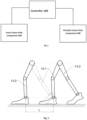
- the apparatus comprises a controller 100, an intact lower-limb component 200 and a paralytic lower-limb component 300 connecting communicatively with the controller 100, wherein the intact lower-limb component 200 is used to be attached to the intact lower-limb of the patient, and the paralytic lower-limb component 300 is used to be attached to the paralytic lower-limb of the patient.
- the controller is used to establish or collect the current state data of the intact lower-limb through the intact lower-limb component, and to determine the current state data of the paralytic lower-limb through the paralytic lower-limb component, for example, the current state may include a lifting state or a supporting state.
- the intact plantar pressure value can be collected through the intact lower-limb component to determine the current state of the intact lower-limb according to the intact plantar pressure value.
- the paralytic plantar pressure value can be collected through the paralytic lower-limb component to determine the current state of the paralytic lower-limb according to the paralytic plantar pressure value.
- the current state of both the intact and paralytic lower-limbs can be determined and get ready for the next step, also the initial states of both the intact and paralytic lower-limb components can be calibrated to allow for best fitting the patient.
- the lifting state or supporting state can be detected by the planter pressure sensors.
- the intact lower-limb component is used to collect the state data of the intact lower-limb while the intact lower-limb is in the lifting state, such as movement data, and send the movement data to the controller.
- the movement data may include one or more of the intact ankle angle value, the intact knee angle value, the intact hip angle value, and the intact plantar pressure value.
- the intact lower-limb component can include a plurality of angle sensors, and each angle sensor is respectively set on the intact ankle joint, the intact knee joint and the intact hip joint of the patient, so as to collect the angle value of the intact ankle joint, the angle value of the intact knee joint and the angle value of the intact hip joint of the patient.
- the controller is used to determine the corresponding state data of the paralytic lower-limb component, such as gait data, according to the movement data of the intact lower-limb, and send the gait data to the paralytic lower-limb component.
- the gait data comprises one or more of walking step length, walking step height, walking step frequency, paralytic ankle angle value, paralytic knee angle value and paralytic hip angle value.
- the walking step length and walking step height of the patient can be determined according to the angle value of the intact hip joint, the angle value of the intact knee joint and the angle value of the intact ankle joint.
- the walking step frequency of the patient is determined according to the length of time while the intact lower-limb is in the lifting state.
- the gait data (including walking step length, walking step height and walking step frequency) corresponding to the paralytic lower-limb component is determined.
- the gait data corresponding to the paralytic lower-limb component can be determined according to the gait data (including walking step length, walking step height and walking step frequency) of the patient determined by the intact lower-limb movement, such as the paralytic ankle angle value, the paralytic knee angle value and the paralytic hip angle value;
- the angle value of the paralytic ankle joint can be determined according to the angle value of the intact ankle joint
- the angle value of the paralytic knee joint can be determined according to the angle value of the intact knee joint
- the angle value of the paralytic hip joint can be determined according to the angle value of the intact hip joint.
- one of the above two solutions can be selected based on the actual situation to calculate the angle value of the paralytic ankle joint, the angle value of the paralytic knee joint and the angle value of
- the paralytic lower-limb component is used to drive the paralytic lower-limb to move according to the gait data while the intact lower-limb is in the supporting state.
- the paralytic lower-limb component may include a plurality of joint drive motors, and each joint drive motor is arranged respectively on the paralytic ankle joint, knee joint and hip joint of the patient to drive the paralytic ankle joint, knee joint and hip joint of the patient to move according to the gait data.
- the controller controls these joint drive motors on the paralytic lower-limb component comprising ankle joint, knee joint and hip joint to drive the movement of the paralytic lower-limb.
- the single-lower-limb rehabilitation exoskeleton apparatus collects the movement data of the intact lower-limb through the intact lower-limb component while the intact lower-limb is in the lifting state, and determines the gait data of the paralytic lower-limb through the controller according to the movement data, so that the paralytic lower-limb component can control the movement of the paralytic lower-limb according to the gait data, and better realize the patient's proactive gait control and the information interaction between the patient and the single-lower-limb rehabilitation exoskeleton apparatus, so as to provide the solutions for the individualized physical rehabilitation training according to the patient's movement data.
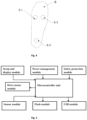
- the intact lower-limb component of the single-lower-limb rehabilitation exoskeleton apparatus provided by the embodiment of the invention also comprises the intact ankle joint sensor, the intact knee joint sensor, the intact hip joint sensor and a plurality of pressure sensors
- the paralytic lower-limb component also comprises the paralytic ankle joint drive motor, the paralytic knee joint drive motor, the paralytic hip joint drive motor and a plurality of pressure sensors.
- the intact lower-limb component and the paralytic lower-limb component also include the fixing units, which can include a plurality of bandages.
- the intact ankle joint sensor is used to collect the angle value of the intact ankle joint
- the intact knee joint sensor is used to collect the angle value of the intact knee joint
- the intact hip joint sensor is used to collect the angle value of the intact hip joint
- each intact pressure sensor is used to collect the intact plantar pressure value.
- the paralytic joint drive motors are used to control the corresponding joint movement of the paralytic lower-limb to the desired paralytic joint angle values according to the gait data.
- the paralytic ankle joint drive motor is used to control the ankle joint movement of the paralytic lower-limb to the desired angle value of the paralytic ankle joint according to the gait data
- the paralytic knee joint drive motor is used to control the knee joint movement of the paralytic lower-limb to the desired angle value of the paralytic knee joint according to the gait data
- the paralytic hip joint drive motor is used to control the movement of the hip joint of the paralytic lower-limb to the desired angle value of the paralytic hip joint according to the gait data
- each paralytic pressure sensor is used to collect the paralytic plantar pressure value of the patient.
- controller is also used to determine the current state of the intact lower-limb according to the intact plantar pressure value of the patient and the current state of the paralytic lower-limb according to the paralytic plantar pressure value.
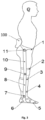
- the implementation of the invention provides a schematic diagram of the lower-limbs of the patient as shown in Fig. 2 , and exemplarily marks the intact lower-limb 13-1 on the intact side and paralytic lower-limb 13-2 on the paralytic side of the patient.
- the embodiment of the invention takes intact lower-limb 13-1 as an example to further explain the single-lower-limb rehabilitation exoskeleton apparatus.
- the belt 1 is used to attach the controller 100 and one end of the hip joint angle sensor (i.e., the intact hip joint sensor 11) at the appropriate position of the patient's waist, and the other end of the hip joint angle sensor is placed on the thigh supporting mechanism close to the waist, and the hip joint angle sensor is located near the rotation center of the hip joint;
- One end of the knee joint angle sensor i.e., the intact side knee joint sensor 9
- One end of the ankle joint angle sensor i.e., the intact side knee joint sensor 9
- the ankle joint angle sensor i.e., the intact ankle joint sensor
- One end of the ankle joint angle sensor i.e., the intact ankle joint sensor 7
- the ankle joint angle sensor is located near the rotation center of the ankle joint.
- Fig. 3 also shows that the fixing unit with the intact lower-limb component also comprises a thigh fixing bandage 2, a lower leg fixing bandage 3 and an ankle fixing bandage 4, which are used to attach the intact lower-limb component to the intact lower-limb of the patient. Furthermore, it is shown in Fig. 3 that the intact lower-limb component also comprises sole supporting mechanism 6, lower leg supporting mechanism 8, thigh supporting mechanism 10 and other supporting parts.
- the fixing unit in the paralytic lower-limb component also comprises thigh fixing bandage, lower leg fixing bandage and ankle fixing bandage, which are used to attach the paralytic lower-limb component to the paralytic lower-limb of the patient.
- the paralytic lower-limb component also includes sole supporting mechanism, lower leg supporting mechanism and thigh supporting mechanism.
- the embodiment of the invention provides a schematic diagram of the arrangement of pressure sensors.
- the intact lower-limb component comprises three intact pressure sensors, as shown in Fig. 4 , it constitutes a pressure sensor array 5 which is provided with a first intact pressure sensor 5.1, the second intact pressure sensor 5.2 and the third intact pressure sensor 5.3.
- the first intact pressure sensor 5.1, the second intact pressure sensor 5.2 and the third intact pressure sensor 5.3 are located at the left front, right front and heel of the sole, respectively.
- the power management module comprises a battery charging management chip, a charging protection circuit, etc., and a customized charger is required for the charging.
- the paralytic lower-limb component also comprises a corresponding joint power supply and a corresponding joint power button connected with the joint drive motor on the paralytic side, and the joint power supply is used to supply power to the corresponding joint drive motor on the paralytic side;
- the joint power button is used for changing the ON and OFF states of the corresponding joint power supply based on the operational need.
- the walking step length and walking step height of the patient can be determined according to the angle value of the intact hip joint, the angle value of the intact knee joint and the angle value of the intact ankle joint;
- the walking step frequency is determined according to the length of time while the intact lower-limb is in lifting state;
- the gait data including walking step, walking height and walking step frequency
- the gait data corresponding to the paralytic lower-limb component is determined;
- the gait data corresponding to the paralytic lower-limb component is determined, such as the paralytic ankle angle value, the paralytic knee angle value and the paralytic hip angle value.
Landscapes
- Health & Medical Sciences (AREA)
- Life Sciences & Earth Sciences (AREA)
- General Health & Medical Sciences (AREA)
- Veterinary Medicine (AREA)
- Public Health (AREA)
- Animal Behavior & Ethology (AREA)
- Physics & Mathematics (AREA)
- Engineering & Computer Science (AREA)
- Heart & Thoracic Surgery (AREA)
- Surgery (AREA)
- Molecular Biology (AREA)
- Medical Informatics (AREA)
- Biomedical Technology (AREA)
- Pathology (AREA)
- Biophysics (AREA)
- Epidemiology (AREA)
- Rehabilitation Therapy (AREA)
- Pain & Pain Management (AREA)
- Physical Education & Sports Medicine (AREA)
- Oral & Maxillofacial Surgery (AREA)
- Dentistry (AREA)
- Physiology (AREA)
- Geometry (AREA)
- Orthopedic Medicine & Surgery (AREA)
- Rehabilitation Tools (AREA)
Claims (4)
- Rehabilitationsexoskelettvorrichtung für eine einzelne untere Gliedmaße, umfassend:eine Steuereinrichtung (100);eine Komponente (200) für eine intakte untere Gliedmaße und eine Komponente (300) für eine paretische untere Gliedmaße, die kommunikativ mit der Steuereinrichtung (100) verbunden sind;wobei die Komponente (200) für eine intakte untere Gliedmaße an einer intakten unteren Gliedmaße (13-1) eines Patienten anzubringen ist bzw. die Komponente für eine paretische untere Gliedmaße an einer paretischen unteren Gliedmaße (13-2) des Patienten anzubringen ist;wobei die Steuereinrichtung (100) Zustandsdaten der intakten unteren Gliedmaße (13-1) durch die Komponente (200) für eine intakte untere Gliedmaße erfasst und die Steuereinrichtung (100) die Komponente (300) für eine paretische untere Gliedmaße gemäß den Zustandsdaten der intakten unteren Gliedmaße (13-1) steuert;wobei die Komponente (200) für eine intakte untere Gliedmaße einen oder mehrere von einem Sprunggelenksensor, einem Kniegelenksensor und einem Hüftgelenksensor umfasst; der Sprunggelenksensor zum Erfassen eines Winkelwerts eines intakten Sprunggelenks des Patienten verwendet wird; der Kniegelenksensor zum Erfassen eines Winkelwerts eines intakten Kniegelenks des Patienten verwendet wird; der Hüftgelenksensor zum Erfassen eines Winkelwerts eines intakten Hüftgelenks des Patienten verwendet wird;wobei die Komponente (300) für eine paretische untere Gliedmaße einen oder mehrere Gelenkantriebsmotoren für ein paretisches Sprunggelenk, ein paretisches Kniegelenk und ein paretisches Hüftgelenk umfasst; die Gelenkantriebsmotoren zum Steuern der Bewegung entsprechender Gelenke der paretischen unteren Gliedmaße (300) gemäß Gelenkwinkelwerten basierend auf Gangdaten verwendet werden;wobei sowohl die Komponente (200, 300) für eine intakte als auch für eine paretische unter Gliedmaße eine Fixiereinheit einschließen; die Fixiereinheit in der Komponente für eine intakte untere Gliedmaße zum Anbringen der Komponente für eine intakte untere Gliedmaße an der intakten unteren Gliedmaße des Patienten verwendet wird, die Fixiereinheit in der Komponente für eine paretische untere Gliedmaße zum Anbringen der Komponente für eine paretische untere Gliedmaße an der paretischen unteren Gliedmaße des Patienten verwendet wird;wobei die Zustandsdaten Bewegungsdaten umfassen, die Bewegungsdaten eines oder mehrere von dem Winkelwert des intakten Sprunggelenks, dem Winkelwert des intakten Kniegelenks und dem Winkelwert des intakten Hüftgelenks auf einer intakten Seite und einem Plantardruckwert auf einer paralytischen Seite umfassen;wobei die Gangdaten eines oder mehrere von einer Gehschrittlänge, einer Gehschritthöhe, einer Gehschrittfrequenz, einem Winkelwert eines paretischen Knöchels, einem Winkelwert eines paretischen Knies, einem Winkelwert einer paretischen Hüfte und einem intakten Plantardruckwert auf der intakten Seite umfassen;wobei die Steuereinrichtung (100) derzeitige Zustandsdaten der intakten unteren Gliedmaße (13-1) und der paretischen unteren Gliedmaße (300) durch die Komponente (200) für eine intakte untere Gliedmaße bzw. die Komponente (300) für eine paretische untere Gliedmaße erfasst;wobei die derzeitigen Zustandsdaten einen Hebezustand oder einen Stützzustand umfassen;wobei die Komponente (200) für eine intakte untere Gliedmaße verwendet wird, um die Bewegungsdaten der intakten unteren Gliedmaße (13-1) zu erfassen, während sich die intakte untere Gliedmaße (13-1) in dem Hebezustand befindet, und die Bewegungsdaten an die Steuereinrichtung (100) zu senden; die Steuereinrichtung (100) die Gangdaten, die der Komponente (300) für eine paretische untere Gliedmaße entsprechen, gemäß den Bewegungsdaten der intakten unteren Gliedmaße (13-1) bestimmt, um die Bewegung der paretischen unteren Gliedmaße (13-2) zu steuern;wobei die Komponente (300) für eine paretische untere Gliedmaße verwendet wird, um die paretische untere Gliedmaße (13-2) so anzutreiben, dass sie sich gemäß den Gangdaten bewegt, während sich die intakte untere Gliedmaße (13-1) in dem Stützzustand befindet;wobei die Komponente (200) für eine intakte untere Gliedmaße einen ersten intakten Drucksensor (5.1), einen zweiten intakten Drucksensor (5.2) und einen dritten intakten Drucksensor (5.3) umfasst, die an der linken Vorderseite, rechten Vorderseite bzw. Ferse einer Sohle eines intakten Fußes angeordnet sind;wobei, während die paralytische untere Gliedmaße (13-2) stillsteht, die intakte untere Gliedmaße (13-1) nach vorne tritt und die Ferse des intakten Fußes langsam einen Boden berührt; ein Druck P3i mit dem dritten Drucksensor (5.3) allmählich erhöht wird, wenn sich eine Sohlenfläche des intakten Fußes dem Boden nähert, der erste Drucksensor (5.1) und der zweite Drucksensor (5.2) unter dem intakten Fuß zunehmende Drücke von P1i und P2i detektieren, falls P1i + P2i + P3i größer als 1/2 eines Körpergewichts G ist und sich dem gesamten Körpergewicht G des Patienten nähert, angegeben wird, dass sich die intakte untere Gliedmaße (13-1) in dem Stützzustand befindet und sich ein Schwerpunkt des Patienten zu verschieben beginnt und die intakte untere Gliedmaße (13-1) allmählich das gesamte Körpergewicht stützt, sich an diesem Punkt die Komponente (300) für eine paralytische untere Gliedmaße zu bewegen beginnt, und wenn P1i + P2i + P3i kleiner als G/2 ist, sich die intakte untere Gliedmaße (13-1) des Patienten in ihrem Hebezustand befindet,wobei die Steuereinrichtung (100) zu Beginn einen Standardsatz der Gangdaten festlegt und dann die Steuereinrichtung (100) die Gangdaten kontinuierlich aktualisiert, während der Patient geht, bis sie mit den Gangcharakteristiken der paralytischen unteren Gliedmaße (13-2) des Patienten konsistent sind.
- Vorrichtung nach Anspruch 1, wobei die Gangdaten den Plantardruckwert auf der paralytischen Seite umfassen.
- Vorrichtung nach einem der Ansprüche 1, 2, wobei die Komponente (300) für eine paretische untere Gliedmaße zudem einen oder mehrere Drucksensoren auf der paretischen Seite umfasst, die verwendet werden, um den Plantardruckwert auf der paretischen Seite des Patienten zu erfassen; die Steuereinrichtung zudem zum Bestimmen des derzeitigen Zustands der paretischen unteren Gliedmaße gemäß dem paretischen Plantardruck verwendet wird.
- Vorrichtung nach Anspruch 3, wobei die Komponente für eine paretische untere Gliedmaße zudem eine entsprechende Gelenkleistungszufuhr und einen entsprechenden Gelenkleistungsknopf umfasst, der mit dem Gelenkantriebsmotor verbunden ist; die Gelenkleistungszufuhr zum Zuführen von Leistung zu dem entsprechenden Gelenkantriebsmotor auf der paretischen Seite verwendet wird; der Gelenkleistungsknopf zum Ändern eines EIN- und AUS-Zustands der entsprechenden Gelenkleistungszufuhr basierend auf einem Betriebsbedarf verwendet wird.
Applications Claiming Priority (2)
| Application Number | Priority Date | Filing Date | Title |
|---|---|---|---|
| CN202010672072.6A CN111773037B (zh) | 2020-07-13 | 2020-07-13 | 单下肢康复外骨骼装置 |
| PCT/CN2021/105892 WO2022012491A1 (en) | 2020-07-13 | 2021-07-13 | Single-lower-limb rehabilitation exoskeleton apparatus and control method |
Publications (3)
| Publication Number | Publication Date |
|---|---|
| EP4178518A1 EP4178518A1 (de) | 2023-05-17 |
| EP4178518A4 EP4178518A4 (de) | 2024-08-14 |
| EP4178518B1 true EP4178518B1 (de) | 2025-07-09 |
Family
ID=72767175
Family Applications (1)
| Application Number | Title | Priority Date | Filing Date |
|---|---|---|---|
| EP21842004.0A Active EP4178518B1 (de) | 2020-07-13 | 2021-07-13 | Rehabilitationsexoskelettvorrichtung mit einem unteren teil und steuerungsverfahren |
Country Status (5)
| Country | Link |
|---|---|
| US (1) | US20230210707A1 (de) |
| EP (1) | EP4178518B1 (de) |
| JP (1) | JP7582712B2 (de) |
| CN (1) | CN111773037B (de) |
| WO (1) | WO2022012491A1 (de) |
Families Citing this family (15)
| Publication number | Priority date | Publication date | Assignee | Title |
|---|---|---|---|---|
| CN111773037B (zh) * | 2020-07-13 | 2023-03-14 | 安杰莱科技(杭州)有限公司 | 单下肢康复外骨骼装置 |
| CN112515923B (zh) * | 2020-12-07 | 2022-11-15 | 深圳市丞辉威世智能科技有限公司 | 下肢外骨骼步态规划方法及计算机可读存储介质、设备 |
| CN114642573B (zh) * | 2021-04-20 | 2024-04-23 | 安杰莱科技(杭州)有限公司 | 一种康复用外骨骼 |
| CN113230094A (zh) * | 2021-05-10 | 2021-08-10 | 深圳市迈步机器人科技有限公司 | 一种单腿外骨骼机器人及其控制方法 |
| CN116077889B (zh) * | 2021-09-22 | 2024-10-22 | 上海海压特智能科技有限公司 | 基于节律性听觉刺激的步态康复训练系统及训练方法 |
| CN114366549B (zh) * | 2021-10-21 | 2024-04-12 | 郑州安杰莱智能科技有限公司 | 一种多自由度踝关节康复训练的装置及其控制方法 |
| CN114533499B (zh) * | 2022-01-19 | 2025-02-18 | 合肥工业大学 | 一种用于下肢辅助器械的控制系统及控制方法 |
| CN114469655B (zh) * | 2022-01-25 | 2023-09-12 | 宁波工业互联网研究院有限公司 | 一种基于重心稳定的下肢外骨骼步态规划方法与系统 |
| CN114795851B (zh) * | 2022-01-27 | 2025-01-21 | 浙江工业大学 | 一种踝足助行器的智能控制方法 |
| CN114948609B (zh) * | 2022-04-12 | 2023-06-16 | 北京航空航天大学 | 一种瘫痪病人的助行辅助装置及方法 |
| CN117021092A (zh) * | 2023-08-18 | 2023-11-10 | 北京机械设备研究所 | 一种适应目标助力需求切换的分时自适应精准助力方法 |
| CN117379284B (zh) * | 2023-09-28 | 2024-10-15 | 南方科技大学 | 髋关节外骨骼的控制方法、装置、终端设备及存储介质 |
| CN116999034B (zh) * | 2023-09-28 | 2023-12-22 | 中国康复科学所(中国残联残疾预防与控制研究中心) | 一种评估系统及评估方法 |
| CN119280004B (zh) * | 2024-10-30 | 2025-12-05 | 贵州航天控制技术有限公司 | 一种下肢康复训练外骨骼控制方法、电子设备、存储介质 |
| CN121313430B (zh) * | 2025-12-10 | 2026-03-24 | 南昌大学第二附属医院 | 一种下肢康复外骨骼机器人控制方法及系统 |
Family Cites Families (21)
| Publication number | Priority date | Publication date | Assignee | Title |
|---|---|---|---|---|
| US20120116258A1 (en) * | 2005-03-24 | 2012-05-10 | Industry-Acadamic Cooperation Foundation, Kyungpook National University | Rehabilitation apparatus using game device |
| JP2006314670A (ja) * | 2005-05-16 | 2006-11-24 | Kenichi Katsura | 歩行補助装置及びリハビリテーションシステム |
| JP2009207840A (ja) * | 2008-03-06 | 2009-09-17 | Toyota Motor Corp | 歩行動作補助装置 |
| WO2009125397A2 (en) * | 2008-04-08 | 2009-10-15 | Motorika Limited | Device and method for foot drop analysis and rehabilitation |
| JP2010148637A (ja) * | 2008-12-25 | 2010-07-08 | Toyota Motor Corp | 歩行補助装置 |
| JP5892506B2 (ja) | 2011-07-04 | 2016-03-23 | 国立大学法人岩手大学 | 健側情報フィードバック型歩行補助装置 |
| US9198821B2 (en) * | 2011-09-28 | 2015-12-01 | Northeastern University | Lower extremity exoskeleton for gait retraining |
| JP2015051065A (ja) | 2013-09-05 | 2015-03-19 | 株式会社安川電機 | 歩行支援情報提示装置 |
| CN103505342B (zh) * | 2013-10-16 | 2014-12-17 | 河北工业大学 | 一种外骨骼式步态康复训练装置 |
| US10390973B2 (en) * | 2015-05-11 | 2019-08-27 | The Hong Kong Polytechnic University | Interactive exoskeleton robotic knee system |
| CN105456004B (zh) * | 2015-12-28 | 2019-02-01 | 中国科学院自动化研究所 | 外骨骼式移动步行康复训练装置及方法 |
| CN105476817A (zh) * | 2016-01-13 | 2016-04-13 | 何平 | 一种人的意念控制机器腿及康复行走方法 |
| TWI606818B (zh) * | 2016-12-23 | 2017-12-01 | 國立陽明大學 | 步態活動促進之電動步行輔具及其應用方法 |
| CN110021398B (zh) * | 2017-08-23 | 2023-03-24 | 陆晓 | 一种步态分析、训练方法及系统 |
| CN108939436B (zh) * | 2018-08-01 | 2020-03-24 | 深圳睿瀚医疗科技有限公司 | 一种健侧患侧协同的主动下肢训练系统及其操作方法 |
| CN109568089A (zh) * | 2019-01-24 | 2019-04-05 | 中国科学技术大学 | 一种随动式下肢步态训练康复机器人系统 |
| CN110812127B (zh) * | 2019-10-16 | 2022-01-04 | 深圳市迈步机器人科技有限公司 | 下肢外骨骼控制方法及装置 |
| CN110974631B (zh) * | 2019-10-23 | 2022-05-17 | 布法罗机器人科技(成都)有限公司 | 一种非对称下肢外骨骼机器人及控制方法 |
| CN111249116A (zh) * | 2020-01-20 | 2020-06-09 | 深圳市丞辉威世智能科技有限公司 | 单侧下肢外骨骼康复装置 |
| US11148279B1 (en) * | 2020-06-04 | 2021-10-19 | Dephy, Inc. | Customized configuration for an exoskeleton controller |
| CN111773037B (zh) * | 2020-07-13 | 2023-03-14 | 安杰莱科技(杭州)有限公司 | 单下肢康复外骨骼装置 |
-
2020
- 2020-07-13 CN CN202010672072.6A patent/CN111773037B/zh active Active
-
2021
- 2021-07-13 JP JP2023521814A patent/JP7582712B2/ja active Active
- 2021-07-13 US US17/926,365 patent/US20230210707A1/en active Pending
- 2021-07-13 EP EP21842004.0A patent/EP4178518B1/de active Active
- 2021-07-13 WO PCT/CN2021/105892 patent/WO2022012491A1/en not_active Ceased
Also Published As
| Publication number | Publication date |
|---|---|
| EP4178518A1 (de) | 2023-05-17 |
| CN111773037A (zh) | 2020-10-16 |
| EP4178518A4 (de) | 2024-08-14 |
| JP2023531830A (ja) | 2023-07-25 |
| CN111773037B (zh) | 2023-03-14 |
| WO2022012491A1 (en) | 2022-01-20 |
| US20230210707A1 (en) | 2023-07-06 |
| JP7582712B2 (ja) | 2024-11-13 |
Similar Documents
| Publication | Publication Date | Title |
|---|---|---|
| EP4178518B1 (de) | Rehabilitationsexoskelettvorrichtung mit einem unteren teil und steuerungsverfahren | |
| EP4161739B1 (de) | Kundenspezifische konfiguration für ein exoskelettsteuergerät | |
| EP2967959B1 (de) | Maschine-mensch-schnittstellen zur kommunikation von einer orthese einer unteren extremität | |
| CN111604890A (zh) | 一种适用于外骨骼机器人的运动控制方法 | |
| CN112370305B (zh) | 一种下肢康复训练外骨骼机器人 | |
| US9375569B2 (en) | Controller unit for a functional electrical stimulation (FES) orthotic system | |
| US20210290482A1 (en) | Wearable Focal Vibration Device and Methods of Use | |
| CN103622792A (zh) | 外骨骼助力机器人的信息采集与控制系统 | |
| CN108836757A (zh) | 一种具有自平衡性的助力行走外骨骼机器人系统 | |
| CN110507322B (zh) | 一种基于虚拟诱导肌电定量状态评估系统及方法 | |
| CN209422174U (zh) | 一种融合视觉的动力假肢环境识别系统 | |
| CN107468486B (zh) | 下肢类脑智能机械电子外骨骼及其综合控制系统 | |
| CN107998609A (zh) | 一种基于多传感器融合的辅助行走外骨骼机器人系统 | |
| CN114903750A (zh) | 一种用于截瘫患者的下肢外骨骼控制系统及下肢外骨骼控制方法 | |
| WO2020112196A1 (en) | Cloud-based control system and method enabling interactive clinical care using a powered mobility assistance device | |
| CN110522600A (zh) | 脑瘫儿童智能踝足矫正训练装置 | |
| CN110292509A (zh) | 一种外骨骼康复机器人控制系统 | |
| CN105342806A (zh) | 一种人体关节运动辅助装置及人体运动助力装置 | |
| CN113230094A (zh) | 一种单腿外骨骼机器人及其控制方法 | |
| CN108938337A (zh) | 一种足踝康复助力型外骨骼装置 | |
| CN110693679A (zh) | 一种智能负重康复助行器 | |
| CN115501089A (zh) | 一种助行设备及其控制方法 | |
| KR20220064912A (ko) | 착용형 로봇 시스템의 크러치 | |
| CN110478100B (zh) | 脑瘫儿童智能踝足矫正训练器 | |
| CN211300971U (zh) | 一种外骨骼康复机器人控制系统 |
Legal Events
| Date | Code | Title | Description |
|---|---|---|---|
| STAA | Information on the status of an ep patent application or granted ep patent |
Free format text: STATUS: THE INTERNATIONAL PUBLICATION HAS BEEN MADE |
|
| PUAI | Public reference made under article 153(3) epc to a published international application that has entered the european phase |
Free format text: ORIGINAL CODE: 0009012 |
|
| STAA | Information on the status of an ep patent application or granted ep patent |
Free format text: STATUS: REQUEST FOR EXAMINATION WAS MADE |
|
| 17P | Request for examination filed |
Effective date: 20230125 |
|
| AK | Designated contracting states |
Kind code of ref document: A1 Designated state(s): AL AT BE BG CH CY CZ DE DK EE ES FI FR GB GR HR HU IE IS IT LI LT LU LV MC MK MT NL NO PL PT RO RS SE SI SK SM TR |
|
| DAV | Request for validation of the european patent (deleted) | ||
| DAX | Request for extension of the european patent (deleted) | ||
| A4 | Supplementary search report drawn up and despatched |
Effective date: 20240717 |
|
| RIC1 | Information provided on ipc code assigned before grant |
Ipc: A61H 1/02 20060101ALI20240711BHEP Ipc: A61B 5/00 20060101ALI20240711BHEP Ipc: A61B 5/107 20060101ALI20240711BHEP Ipc: A61B 5/103 20060101ALI20240711BHEP Ipc: A61B 5/11 20060101ALI20240711BHEP Ipc: A61H 3/00 20060101AFI20240711BHEP |
|
| GRAP | Despatch of communication of intention to grant a patent |
Free format text: ORIGINAL CODE: EPIDOSNIGR1 |
|
| STAA | Information on the status of an ep patent application or granted ep patent |
Free format text: STATUS: GRANT OF PATENT IS INTENDED |
|
| INTG | Intention to grant announced |
Effective date: 20250331 |
|
| GRAS | Grant fee paid |
Free format text: ORIGINAL CODE: EPIDOSNIGR3 |
|
| GRAA | (expected) grant |
Free format text: ORIGINAL CODE: 0009210 |
|
| STAA | Information on the status of an ep patent application or granted ep patent |
Free format text: STATUS: THE PATENT HAS BEEN GRANTED |
|
| AK | Designated contracting states |
Kind code of ref document: B1 Designated state(s): AL AT BE BG CH CY CZ DE DK EE ES FI FR GB GR HR HU IE IS IT LI LT LU LV MC MK MT NL NO PL PT RO RS SE SI SK SM TR |
|
| REG | Reference to a national code |
Ref country code: GB Ref legal event code: FG4D |
|
| REG | Reference to a national code |
Ref country code: CH Ref legal event code: EP |
|
| REG | Reference to a national code |
Ref country code: IE Ref legal event code: FG4D |
|
| REG | Reference to a national code |
Ref country code: DE Ref legal event code: R096 Ref document number: 602021033941 Country of ref document: DE |
|
| PGFP | Annual fee paid to national office [announced via postgrant information from national office to epo] |
Ref country code: DE Payment date: 20250826 Year of fee payment: 5 |
|
| PGFP | Annual fee paid to national office [announced via postgrant information from national office to epo] |
Ref country code: GB Payment date: 20250901 Year of fee payment: 5 |
|
| PGFP | Annual fee paid to national office [announced via postgrant information from national office to epo] |
Ref country code: AT Payment date: 20251020 Year of fee payment: 5 Ref country code: FR Payment date: 20250902 Year of fee payment: 5 |
|
| REG | Reference to a national code |
Ref country code: NL Ref legal event code: MP Effective date: 20250709 |
|
| PG25 | Lapsed in a contracting state [announced via postgrant information from national office to epo] |
Ref country code: PT Free format text: LAPSE BECAUSE OF FAILURE TO SUBMIT A TRANSLATION OF THE DESCRIPTION OR TO PAY THE FEE WITHIN THE PRESCRIBED TIME-LIMIT Effective date: 20251110 |
|
| PG25 | Lapsed in a contracting state [announced via postgrant information from national office to epo] |
Ref country code: NL Free format text: LAPSE BECAUSE OF FAILURE TO SUBMIT A TRANSLATION OF THE DESCRIPTION OR TO PAY THE FEE WITHIN THE PRESCRIBED TIME-LIMIT Effective date: 20250709 |
|
| REG | Reference to a national code |
Ref country code: AT Ref legal event code: MK05 Ref document number: 1811155 Country of ref document: AT Kind code of ref document: T Effective date: 20250709 |
|
| PG25 | Lapsed in a contracting state [announced via postgrant information from national office to epo] |
Ref country code: IS Free format text: LAPSE BECAUSE OF FAILURE TO SUBMIT A TRANSLATION OF THE DESCRIPTION OR TO PAY THE FEE WITHIN THE PRESCRIBED TIME-LIMIT Effective date: 20251109 |
|
| PG25 | Lapsed in a contracting state [announced via postgrant information from national office to epo] |
Ref country code: NO Free format text: LAPSE BECAUSE OF FAILURE TO SUBMIT A TRANSLATION OF THE DESCRIPTION OR TO PAY THE FEE WITHIN THE PRESCRIBED TIME-LIMIT Effective date: 20251009 |
|
| REG | Reference to a national code |
Ref country code: LT Ref legal event code: MG9D |
|
| PG25 | Lapsed in a contracting state [announced via postgrant information from national office to epo] |
Ref country code: AT Free format text: LAPSE BECAUSE OF FAILURE TO SUBMIT A TRANSLATION OF THE DESCRIPTION OR TO PAY THE FEE WITHIN THE PRESCRIBED TIME-LIMIT Effective date: 20250709 |
|
| PG25 | Lapsed in a contracting state [announced via postgrant information from national office to epo] |
Ref country code: FI Free format text: LAPSE BECAUSE OF FAILURE TO SUBMIT A TRANSLATION OF THE DESCRIPTION OR TO PAY THE FEE WITHIN THE PRESCRIBED TIME-LIMIT Effective date: 20250709 |
|
| PGFP | Annual fee paid to national office [announced via postgrant information from national office to epo] |
Ref country code: IT Payment date: 20251030 Year of fee payment: 5 |
|
| PG25 | Lapsed in a contracting state [announced via postgrant information from national office to epo] |
Ref country code: HR Free format text: LAPSE BECAUSE OF FAILURE TO SUBMIT A TRANSLATION OF THE DESCRIPTION OR TO PAY THE FEE WITHIN THE PRESCRIBED TIME-LIMIT Effective date: 20250709 |
|
| PG25 | Lapsed in a contracting state [announced via postgrant information from national office to epo] |
Ref country code: GR Free format text: LAPSE BECAUSE OF FAILURE TO SUBMIT A TRANSLATION OF THE DESCRIPTION OR TO PAY THE FEE WITHIN THE PRESCRIBED TIME-LIMIT Effective date: 20251010 |
|
| PG25 | Lapsed in a contracting state [announced via postgrant information from national office to epo] |
Ref country code: SE Free format text: LAPSE BECAUSE OF FAILURE TO SUBMIT A TRANSLATION OF THE DESCRIPTION OR TO PAY THE FEE WITHIN THE PRESCRIBED TIME-LIMIT Effective date: 20250709 |
|
| PG25 | Lapsed in a contracting state [announced via postgrant information from national office to epo] |
Ref country code: LV Free format text: LAPSE BECAUSE OF FAILURE TO SUBMIT A TRANSLATION OF THE DESCRIPTION OR TO PAY THE FEE WITHIN THE PRESCRIBED TIME-LIMIT Effective date: 20250709 |
|
| PG25 | Lapsed in a contracting state [announced via postgrant information from national office to epo] |
Ref country code: BG Free format text: LAPSE BECAUSE OF FAILURE TO SUBMIT A TRANSLATION OF THE DESCRIPTION OR TO PAY THE FEE WITHIN THE PRESCRIBED TIME-LIMIT Effective date: 20250709 Ref country code: PL Free format text: LAPSE BECAUSE OF FAILURE TO SUBMIT A TRANSLATION OF THE DESCRIPTION OR TO PAY THE FEE WITHIN THE PRESCRIBED TIME-LIMIT Effective date: 20250709 |
|
| PG25 | Lapsed in a contracting state [announced via postgrant information from national office to epo] |
Ref country code: RS Free format text: LAPSE BECAUSE OF FAILURE TO SUBMIT A TRANSLATION OF THE DESCRIPTION OR TO PAY THE FEE WITHIN THE PRESCRIBED TIME-LIMIT Effective date: 20251009 |
|
| PG25 | Lapsed in a contracting state [announced via postgrant information from national office to epo] |
Ref country code: ES Free format text: LAPSE BECAUSE OF FAILURE TO SUBMIT A TRANSLATION OF THE DESCRIPTION OR TO PAY THE FEE WITHIN THE PRESCRIBED TIME-LIMIT Effective date: 20250709 |
|
| REG | Reference to a national code |
Ref country code: CH Ref legal event code: H13 Free format text: ST27 STATUS EVENT CODE: U-0-0-H10-H13 (AS PROVIDED BY THE NATIONAL OFFICE) Effective date: 20260224 |
|
| PG25 | Lapsed in a contracting state [announced via postgrant information from national office to epo] |
Ref country code: RO Free format text: LAPSE BECAUSE OF FAILURE TO SUBMIT A TRANSLATION OF THE DESCRIPTION OR TO PAY THE FEE WITHIN THE PRESCRIBED TIME-LIMIT Effective date: 20250709 Ref country code: LU Free format text: LAPSE BECAUSE OF NON-PAYMENT OF DUE FEES Effective date: 20250713 |