EP4178124A1 - Image processing device and image processing method - Google Patents
Image processing device and image processing method Download PDFInfo
- Publication number
- EP4178124A1 EP4178124A1 EP21831594.3A EP21831594A EP4178124A1 EP 4178124 A1 EP4178124 A1 EP 4178124A1 EP 21831594 A EP21831594 A EP 21831594A EP 4178124 A1 EP4178124 A1 EP 4178124A1
- Authority
- EP
- European Patent Office
- Prior art keywords
- access point
- processing portion
- image data
- radio wave
- image forming
- Prior art date
- Legal status (The legal status is an assumption and is not a legal conclusion. Google has not performed a legal analysis and makes no representation as to the accuracy of the status listed.)
- Granted
Links
Images




Classifications
-
- H—ELECTRICITY
- H04—ELECTRIC COMMUNICATION TECHNIQUE
- H04W—WIRELESS COMMUNICATION NETWORKS
- H04W48/00—Access restriction; Network selection; Access point selection
- H04W48/16—Discovering, processing access restriction or access information
-
- B—PERFORMING OPERATIONS; TRANSPORTING
- B41—PRINTING; LINING MACHINES; TYPEWRITERS; STAMPS
- B41J—TYPEWRITERS; SELECTIVE PRINTING MECHANISMS, i.e. MECHANISMS PRINTING OTHERWISE THAN FROM A FORME; CORRECTION OF TYPOGRAPHICAL ERRORS
- B41J29/00—Details of, or accessories for, typewriters or selective printing mechanisms not otherwise provided for
- B41J29/38—Drives, motors, controls or automatic cut-off devices for the entire printing mechanism
-
- H—ELECTRICITY
- H04—ELECTRIC COMMUNICATION TECHNIQUE
- H04N—PICTORIAL COMMUNICATION, e.g. TELEVISION
- H04N1/00—Scanning, transmission or reproduction of documents or the like, e.g. facsimile transmission; Details thereof
- H04N1/00002—Diagnosis, testing or measuring; Detecting, analysing or monitoring not otherwise provided for
- H04N1/00005—Diagnosis, testing or measuring; Detecting, analysing or monitoring not otherwise provided for relating to image data
-
- H—ELECTRICITY
- H04—ELECTRIC COMMUNICATION TECHNIQUE
- H04N—PICTORIAL COMMUNICATION, e.g. TELEVISION
- H04N1/00—Scanning, transmission or reproduction of documents or the like, e.g. facsimile transmission; Details thereof
- H04N1/00127—Connection or combination of a still picture apparatus with another apparatus, e.g. for storage, processing or transmission of still picture signals or of information associated with a still picture
- H04N1/00281—Connection or combination of a still picture apparatus with another apparatus, e.g. for storage, processing or transmission of still picture signals or of information associated with a still picture with a telecommunication apparatus, e.g. a switched network of teleprinters for the distribution of text-based information, a selective call terminal
- H04N1/00315—Connection or combination of a still picture apparatus with another apparatus, e.g. for storage, processing or transmission of still picture signals or of information associated with a still picture with a telecommunication apparatus, e.g. a switched network of teleprinters for the distribution of text-based information, a selective call terminal with a radio transmission apparatus
-
- H—ELECTRICITY
- H04—ELECTRIC COMMUNICATION TECHNIQUE
- H04N—PICTORIAL COMMUNICATION, e.g. TELEVISION
- H04N1/00—Scanning, transmission or reproduction of documents or the like, e.g. facsimile transmission; Details thereof
- H04N1/32—Circuits or arrangements for control or supervision between transmitter and receiver or between image input and image output device, e.g. between a still-image camera and its memory or between a still-image camera and a printer device
- H04N1/32101—Display, printing, storage or transmission of additional information, e.g. ID code, date and time or title
- H04N1/32106—Display, printing, storage or transmission of additional information, e.g. ID code, date and time or title separate from the image data, e.g. in a different computer file
-
- Y—GENERAL TAGGING OF NEW TECHNOLOGICAL DEVELOPMENTS; GENERAL TAGGING OF CROSS-SECTIONAL TECHNOLOGIES SPANNING OVER SEVERAL SECTIONS OF THE IPC; TECHNICAL SUBJECTS COVERED BY FORMER USPC CROSS-REFERENCE ART COLLECTIONS [XRACs] AND DIGESTS
- Y02—TECHNOLOGIES OR APPLICATIONS FOR MITIGATION OR ADAPTATION AGAINST CLIMATE CHANGE
- Y02D—CLIMATE CHANGE MITIGATION TECHNOLOGIES IN INFORMATION AND COMMUNICATION TECHNOLOGIES [ICT], I.E. INFORMATION AND COMMUNICATION TECHNOLOGIES AIMING AT THE REDUCTION OF THEIR OWN ENERGY USE
- Y02D30/00—Reducing energy consumption in communication networks
- Y02D30/70—Reducing energy consumption in communication networks in wireless communication networks
Definitions
- the present invention relates to an image processing apparatus and an image processing method.
- an image forming apparatus equipped with a wireless LAN has been used.
- a personal computer PC
- AP access point
- the image forming apparatus can perform printing processing or transfer image data scanned by the image forming apparatus to the PC.
- the image forming apparatus may experience slow communication speed or disconnection in an environment where many devices are connected by a wireless LAN or an environment where a device, such as a microwave oven, using radio waves in the same frequency band is placed nearby.
- the image forming apparatus when the image forming apparatus is connected to a device by a wired LAN, a cable is used for the connection; therefore, when the connection between the devices is broken, it is possible to visually identify the cause such as a disconnected cable or a hub connecting the cable that is not turned on.
- the communication speed when the communication speed is low, it is assumed that there are many PCs connected to the network or that the amount of communication data has temporarily increased, and the cause can be identified by capturing packets flowing through the cable.
- the image forming apparatus when the image forming apparatus is connected to a device by a wireless LAN, there may be an influence of radio wave strength or radio wave interference, and it is difficult to visually identify the cause of communication interference. Therefore, when the connection between the devices is broken, it is difficult to identify the cause. In addition, since the communication speed is affected by the magnitude of the radio wave strength, the amount of data flowing through the network, and the like, it is also difficult to identify the cause of a decrease in the communication speed.
- Patent Literature 1 Japanese Unexamined Patent Application Publication No. 2019-179577
- An object of the present invention is to provide an image processing apparatus and an image processing method capable of presenting information relating to a communication environment to a user in an image processing apparatus connected to a device by a wireless LAN.
- An image processing apparatus comprises a connection processing portion, a detection processing portion, a transmission/reception processing portion, and an output processing portion.
- the connection processing portion performs wireless connection to a predetermined access point.
- the detection processing portion detects the radio wave strength of the access point.
- the transmission/reception processing portion transmits and receives image data to and from a device connected to the access point.
- the output processing portion outputs communication environment information including the radio wave strength of the access point at the time of transmission and reception of the image data.
- An image processing method includes a connection step, a detection step, a transmission/reception step, and an output step.
- connection step wireless connection to a predetermined access point is performed.
- detection step the radio wave strength of the access point is detected.
- transmission/reception step image data is transmitted and received to and from a device connected to the access point.
- output step communication environment information including the radio wave strength of the access point at the time of transmission and reception of the image data is output.
- an image processing apparatus and an image processing method capable of presenting information relating to a communication environment to a user in an image processing apparatus connected to a device by a wireless LAN.
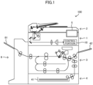
- an image forming apparatus 100 includes an image reading portion 1, an automatic document feeder (ADF) 2, an image forming portion 3, a sheet feed portion 4, an operation display portion 5, a discharge portion 6, a storage portion 7 (see FIG. 2 ), a communication portion 8 (see FIG. 2 ), a control portion 10, and the like.
- the image forming apparatus 100 is a multifunction peripheral having a plurality of functions such as a facsimile function for reading an image from a document sheet to obtain image data, a print function for forming an image based on image data, and a copy function. It is noted that the image forming apparatus 100 may be a printer, a facsimile machine, a copier, or the like.
- the image forming apparatus 100 is an example of the image processing apparatus of the present invention.
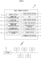
- the communication portion 8 is a communication interface for wirelessly connecting the image forming apparatus 100 to an access point AP connected to a network N1 and performing data communication according to a predetermined communication protocol with an external device, such as a personal computer (PC), via the access point AP.
- the communication portion 8 is provided with a wireless LAN interface.
- the access point AP is an IEEE802.11 (Wi-Fi) or other standard wireless LAN (Local Area Network) access point, a wireless LAN router, a wireless LAN-wired LAN network converter, a server with a built-in wireless LAN interface, or the like.
- the access point AP transmits a packet acquired from each device to the network N1, and causes a packet in the network N1 to be transmitted to each device.
- the access point AP can connect devices by causing the devices to perform packet communication with each other through a wireless LAN.
- the access point AP may be capable of transmitting an SSID (Service Set Identifier), which is the identification name (network name) of the access point in the wireless LAN (Wi-Fi), to each device.
- SSID Service Set Identifier
- the network N1 is a wired LAN such as an intranet, the Internet, a WAN (Wide Area Network) such as a mobile phone network, or the like.
- a WAN Wide Area Network
- the network N1 may be connectable to another server via a router, a gateway, or the like.
- the network N1 may constitute a VPN (Virtual Private Network).
- FIG. 2 illustrates three access points AP1, AP2, and AP3.
- the access points AP1, AP2, and AP3 use, for example, the 2.4 GHz frequency band.
- the network N1 constitutes an internal LAN in a specific office, and a plurality of PCs (for example, PC1 and PC2) used by respective users are connected to the network N1.
- a user A transfers image data from PC1 to the image forming apparatus 100 via the access point AP1, and causes the image forming apparatus 100 to execute printing processing.
- a user B causes the image forming apparatus 100 to scan an image and transfer the scanned image data to PC2 via the access point AP2.
- a user such as a network administrator can designate an access point AP to which the image forming apparatus 100 is to be connected.
- the user designates an access point AP suitable for transmission and reception (transfer processing) of image data based on the communication environment of the image forming apparatus 100, and causes the image forming apparatus 100 to connect to the access point AP.
- FIG. 3 is a graph showing the status of radio wave strength of each of the access points AP1, AP2, and AP3 detected in the image forming apparatus 100.
- the control portion 10 (detection processing portion 112) of the image forming apparatus 100 can detect the radio wave strength of each of the access points AP1, AP2, and AP3 at the installation site of the image forming apparatus 100.
- the image forming apparatus 100 detects the radio wave strengths of an access point AP used in each communication channel and a device (PC) connected to the access point AP. In addition, the image forming apparatus 100 causes the operation display portion 5 of the image forming apparatus 100, the user's PC, or the like to display the graph shown in FIG. 3 as the detection result of the radio wave strengths. In addition, the image forming apparatus 100 may print out the detection result as a report. This allows the user to grasp the number of devices using the wireless LAN and the radio wave strength of each device and each access point AP.
- the user selects (designates) an access point AP to be used for transferring image data with reference to the detection result.
- the example shown in FIG. 3 shows that the access point AP1 has the highest radio wave strength as the radio wave received by the image forming apparatus 100, and that the number of devices connected to a channel 1 is small and the interference is relatively small. Therefore, the user can determine that the access point AP1 is the optimum access point AP to which the image forming apparatus 100 is to be connected, and designate the access point AP1.
- the control portion 10 (connection processing portion 111) of the image forming apparatus 100 connects the image forming apparatus 100 to the designated access point AP. In this way, the image forming apparatus 100 can connect to the access point AP designated by the user.
- the image reading portion 1 includes a contact glass, a reading unit, a mirror, an optical lens, a CCD (Charge Coupled Device), and the like.
- the ADF 2 includes a document sheet loading portion, a plurality of conveying rollers, a document sheet holder, and a sheet discharge portion, and conveys a document sheet to be read by the image reading portion 1.
- the image forming portion 3 can form an image on a sheet by an electrophotographic method based on image data obtained at the image reading portion 1.
- the image forming portion 3 can also form an image on a sheet based on image data input from an external device (for example, a user's PC).
- the image forming portion 3 includes a photoconductor drum, a charging device, a laser scanning unit (LSU), a developing device, a transfer roller, a cleaning device, a fixing roller, and a pressure roller. It is noted that the image forming portion 3 may form an image on a sheet by another image forming method such as an inkjet method.
- the image forming portion 3 conveys a sheet (printing sheet) on which an image has been formed to the discharge portion 6.
- the sheet feed portion 4 includes a sheet storing portion 41 and a plurality of conveying rollers, and supplies a sheet to the image forming portion 3.
- the sheet feed portion 4 is controlled by the control portion 10 to convey a sheet stored in the sheet storing portion 41 to the image forming portion 3.
- the sheet feed portion 4 includes a manual feed tray 42 on which a user manually (by a manual feed) sets a sheet.
- the sheet feed portion 4 is controlled by the control portion 10 to convey a sheet set on the manual feed tray 42 to the image forming portion 3.
- the sheet storing portion 41 is provided on the lower side as viewed from the front of the image forming apparatus 100
- the manual feed tray 42 is provided on the right side as viewed from the front of the image forming apparatus 100.
- the discharge portion 6 discharges a printing sheet on which an image has been formed by the image forming portion 3.
- the discharge portion 6 includes one or more discharge trays 61. When a plurality of discharge trays 61 are provided, the discharge trays 61 are provided at positions different in height from the installation surface (floor surface) of the image forming apparatus 100.
- the discharge portion 6 is controlled by the control portion 10 to discharge the printing sheet to a predetermined discharge tray 61.
- the discharge portion 6 discharges the printing sheet to a determined discharge tray 61 in accordance with a command of the control portion 10.
- the discharge tray 61 is provided on the left side as viewed from the front of the image forming apparatus 100.
- the operation display portion 5 includes a display portion such as a liquid crystal display for displaying various types of information in response to a command of the control portion 10, and an operation portion such as an operation key or a touch panel for inputting various types of information to the control portion 10 in response to a user's operation.
- a display portion such as a liquid crystal display for displaying various types of information in response to a command of the control portion 10
- an operation portion such as an operation key or a touch panel for inputting various types of information to the control portion 10 in response to a user's operation.
- the storage portion 7 is a nonvolatile storage device.
- the storage portion 7 is a storage device such as a nonvolatile memory including a flash memory, an EEPROM (registered trademark), and the like, an SSD, or an HDD.
- the storage portion 7 stores various control programs such as an information presentation program for causing the control portion 10 to execute information presentation processing (see FIG. 6 ) to be described later, various types of data, and the like.
- the control portion 10 includes control devices such as a CPU, a ROM, and a RAM.
- the CPU is a processor that executes various types of arithmetic processing.
- the ROM is a nonvolatile storage portion in which information such as control programs for causing the CPU to execute various types of processing are stored in advance.
- the RAM is a volatile or nonvolatile storage portion used as a temporary storage memory (work area) for various types of processing executed by the CPU.
- the image forming apparatus 100 can present information relating to the communication environment to the user.
- the control portion 10 includes various processing portions such as a connection processing portion 111, a detection processing portion 112, a transmission/reception processing portion 113, a determination processing portion 114, and an output processing portion 115. It is noted that the control portion 10 functions as the various processing portions by executing various types of processing according to the information presentation program at the CPU. In addition, some or all of the processing portions included in the control portion 10 may be constituted by electronic circuits. It is noted that the information presentation program may be a program for causing a plurality of processors to function as the various processing portions.
- the connection processing portion 111 wirelessly connects the image forming apparatus 100 to a predetermined access point AP. For example, when the user designates a predetermined access point AP on a setting screen displayed on the operation display portion 5 of the image forming apparatus 100, the connection processing portion 111 connects the image forming apparatus 100 to the designated access point AP. When the connection between the image forming apparatus 100 and the access point AP is established, data communication via the access point AP becomes possible between the image forming apparatus 100 and a device connected to the network N1. As the connection method to the access point AP, a well-known technique can be applied.
- the connection processing portion 111 is an example of the connection processing portion of the present invention.
- the detection processing portion 112 detects the radio wave strength of an access point AP. For example, as described above, the detection processing portion 112 detects the radio wave strength of each of a plurality of access points AP from which the image forming apparatus 100 can receive radio waves (see FIG. 3 ).
- the detection processing portion 112 detects the radio wave strength of a specific access point AP connected by the connection processing portion 111. For example, when the power of the image forming apparatus 100 is turned on and the image forming apparatus 100 is connected to the designated access point AP, the detection processing portion 112 starts detection processing of the radio wave strength of the access point AP. The detection processing portion 112 continues the detection processing until the connection between the image forming apparatus 100 and the access point AP is interrupted (predetermined period). In addition, in the detection processing, the detection processing portion 112 detects the radio wave strength when the transmission/reception processing portion 113 transmits and receives image data. That is, the detection processing portion 112 detects the radio wave strength of the access point AP1 at the time of transmission and reception of the image data. The detection processing portion 112 stores the detection result of the predetermined period in the storage portion 7.
- the user may be able to set the period during which the detection processing is executed in the image forming apparatus 100.
- the user may be able to set a start date and time and an end date and time of the detection processing on the setting screen.
- the detection processing portion 112 executes the detection processing only for the period set by the user.
- the transmission/reception processing portion 113 transmits and receives image data to and from a device connected to the access point AP. Specifically, the transmission/reception processing portion 113 transmits and receives image data to and from a device (PC) connected to a specific access point AP connected by the connection processing portion 111. For example, when the image forming apparatus 100 is connected to the access point AP1 and image data for printing is output from PC1, the transmission/reception processing portion 113 receives the image data transferred from the access point AP1. When the transmission/reception processing portion 113 acquires the image data, the image forming portion 3 forms an image on a sheet based on the image data.
- PC device
- the transmission/reception processing portion 113 outputs image data obtained by the image reading portion 1 to the access point AP1.
- the access point AP1 transfers the received image data to PC2.
- the transmission/reception processing portion 113 transmits and receives the image data by packet communication.
- a transfer error may occur in which some packets of the image data are not transferred normally. Such a transfer error is likely to occur when the data amount of image data is large or when the communication environment is not good.
- the determination processing portion 114 determines whether or not the image data has been transferred normally. Then, the transmission/reception processing portion 113 detects the data amount (for example, the number of packets) of the image data, the number of packets of the image data that have been transferred normally (normal transfer packets) (the number of normal transfer packets), and the number of packets of the image data that have not been transferred normally (error transfer packets) (the number of error transfer packets). The transmission/reception processing portion 113 stores these detection results in the storage portion 7.
- the data amount for example, the number of packets
- normal transfer packets the number of packets of the image data that have been transferred normally
- error transfer packets the number of packets of the image data that have not been transferred normally
- the control portion 10 generates detection log information D1 based on the detection result of the detection processing portion 112 and the detection results of the transmission/reception processing portion 113, and stores the detection log information D1 in the storage portion 7.
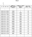
- FIG. 4 shows an example of the detection log information D1.
- the detection log information D1 includes information such as the number of normal transfer packets, the number of error transfer packets, and the radio wave strength for each set date and time.
- the set date and time is a date and time set in advance by the user, and is set, for example, at an hourly time (every hour on the hour) in the use time period in which the image forming apparatus 100 is used. It is noted that the set date and time is not limited to every hour on the hour, and may be every two hours, every week, or every month.
- the number of normal transfer packets is information calculated based on the normal transfer packets detected by the transmission/reception processing portion 113.
- the control portion 10 registers, as the number of normal transfer packets, the number of packets obtained by adding up the normal transfer packets detected by the transmission/reception processing portion 113 every hour.
- the number of error transfer packets is information calculated based on the error transfer packets detected by the transmission/reception processing portion 113.
- the control portion 10 registers, as the number of error transfer packets, the number of packets obtained by adding up the error transfer packets detected by the transmission/reception processing portion 113 every hour.
- the radio wave strength is information calculated based on the radio wave strength detected by the detection processing portion 112.
- the control portion 10 registers, as the radio wave strength, an average value obtained by averaging the radio wave strengths detected by the detection processing portion 112 at the time of transmission and reception of image data every hour. It is noted that the control portion 10 may register, as the radio wave strength, the maximum value or the minimum value of the radio wave strength for each hour.
- control portion 10 generates the detection log information D1 in association with the data amount of the image data (the number of normal transfer packets, the number of error transfer packets) and the radio wave strength.
- the control portion 10 registers each type of information in the detection log information D1, for example, every hour.
- FIG. 4 shows detection log information D1 corresponding to a specific access point AP designated by the user.
- the detection processing portion 112 detects the radio wave strength of the switched access point AP, and the transmission/reception processing portion 113 transmits and receives image data via the switched access point AP.
- the control portion 10 generates detection log information D1 corresponding to the switched access point AP. Therefore, the storage portion 7 stores detection log information D1 for each access point AP. For example, when the image forming apparatus 100 has a record of using the access points AP1, AP2, and AP3, detection log information D1 corresponding to each of the access points AP1, AP2, and AP3 is stored in the storage portion 7.
- the output processing portion 115 outputs communication environment information including the radio wave strength of the access point AP at the time of transmission and reception of the image data.
- the communication environment information is information used when the user selects an access point AP to which the image forming apparatus 100 is to be connected, and the user can designate a specific access point AP by referring to the communication environment information.
- the output processing portion 115 causes the communication environment information to be displayed on at least one of the image forming apparatus 100 and the PC.
- the output processing portion 115 outputs communication environment information in which the data amount (the number of packets) of the image data and the radio wave strength of the access point AP are associated with each other.
- the output processing portion 115 may further output a determination result as to whether or not image data has been transferred normally.
- the output processing portion 115 outputs communication environment information in which the data amount of the image data, the radio wave strength of the access point AP, and the determination result (transfer success, transfer failure, etc.) are associated with each other.
- the output processing portion 115 may output communication environment information in which the number of packets of the image data that have been transferred normally (the number of normal transfer packets), the number of packets of the image data that have not been transferred normally (the number of error transfer packets), and the radio wave strength of the access point AP are associated with each other.
- the output processing portion 115 may output communication environment information indicating changes in the data amount of the image data and the radio wave strength of the access point AP during a predetermined period (for example, one day, one week, one month, etc.).
- the output processing portion 115 presents the detection log information D1 (see FIG. 4 ) generated by the control portion 10 to the user.
- the output processing portion 115 causes a predetermined PC or the operation display portion 5 of the image forming apparatus 100 to display the detection log information D1.
- the detection log information D1 is an example of the communication environment information of the present invention.
- the output processing portion 115 may present a graph corresponding to the detection log information D1 to the user so that the user can easily understand how the radio wave strength has changed.
- FIG. 5 shows an example of the graph generated by the control portion 10 based on the detection log information D1.
- the control portion 10 generates detection log information D1 based on the detection results of the detection processing portion 112 and the transmission/reception processing portion 113, and generates a graph based on the detection log information D1.
- the graph is an example of the communication environment information of the present invention. This allows the user to easily grasp the magnitude of the radio wave strength at the time of transmission and reception of the image data, the number of packets per hour, and how the number of packets and the radio wave strength change.
- the output processing portion 115 when the user selects an access point AP and performs an operation to request communication environment information on the setting screen, the output processing portion 115 presents the detection log information D1 corresponding to the access point AP (see FIG. 4 ) or the graph (see FIG. 5 ) to the user. In addition, the output processing portion 115 may output the communication environment information corresponding to a plurality of access points AP. In addition, the output processing portion 115 may print out the communication environment information (detection log information D1, the graph) in the image forming apparatus 100.
- the present invention can be understood as an invention of an information presentation method for executing one or more steps included in the information presentation processing.
- the information presentation method is an example of the image processing method of the present invention.
- the control portion 10 receives an operation for designating an access point AP from a user (for example, a network administrator). For example, when the user selects, on the setting screen, one access point AP from a list of access points AP from which the image forming apparatus 100 can receive radio waves, the control portion 10 acquires identification information of the access point AP.
- a user for example, a network administrator.
- step S12 the control portion 10 executes connection processing for connecting the image forming apparatus 100 to the designated access point AP.
- connection processing for connecting the image forming apparatus 100 to the designated access point AP.
- data communication via the access point AP becomes possible between the image forming apparatus 100 and a device connected to the network N1.
- Step S12 is an example of the connection step of the present invention.
- step S13 the control portion 10 starts detection processing of the radio wave strength of the access point AP connected to the image forming apparatus 100.
- the control portion 10 detects the radio wave strength at a predetermined sampling period.
- the control portion 10 stores the detection result in the storage portion 7.
- Step S13 is an example of the detection step of the present invention.
- step S14 the control portion 10 determines whether or not image data has been transmitted or received.
- the control portion 10 determines that image data has been transmitted or received (Yes in S14)
- the processing proceeds to step S15.
- the control portion 10 detects the radio wave strength of the access point AP at the time of transmission or reception of the image data.
- the control portion 10 stores the radio wave strength detected at the time of transmission or reception of the image data in the storage portion 7.
- Step S14 is an example of the transmission/reception step of the present invention.
- step S15 the control portion 10 determines whether or not the image data has been transferred normally (success or failure). The control portion 10 determines the success or failure of the transfer of the image data based on the number of packets of the image data.
- step S16 the control portion 10 detects the number of normal transfer packets and the number of error transfer packets of the image data based on the determination result in step S15.
- step S17 the control portion 10 generates detection log information D1 (see FIG. 4 ) based on the radio wave strength at the time of transmission or reception of the image data and the number of normal transfer packets and the number of error transfer packets of the image data, and stores the detection log information D1 in the storage portion 7. It is noted that when the control portion 10 does not determine that the image data has been transmitted or received in step S14 (No in S14), the control portion 10 registers the radio wave strength corresponding to the set time in the detection log information D1.
- step S18 the control portion 10 determines whether or not a request for presentation of communication environment information has been received from the user.
- the processing proceeds to step S19.
- the control portion 10 has not received the presentation request from the user (No in S18)
- the processing returns to step S13.
- the control portion 10 repeats the processing described above.
- step S19 the control portion 10 presents the communication environment information to the user.
- the control portion 10 causes the user's PC or the operation display portion 5 of the image forming apparatus 100 to display the detection log information D1 (see FIG. 4 ).
- the control portion 10 may cause the user's PC or the operation display portion 5 of the image forming apparatus 100 to display the graph (see FIG. 5 ) generated based on the detection log information D1.
- the control portion 10 may cause the image forming apparatus 100 to print out the communication environment information (detection log information D1, the graph) as a report.
- Step S19 is an example of the output step of the present invention.
- the control portion 10 executes the information presentation processing as described above.
- the control portion 10 executes the information presentation processing every time an access point AP is designated by the user.
- the image forming apparatus 100 wirelessly connects to a predetermined access point AP, and outputs communication environment information including the radio wave strength of the access point AP at the time of transmission or reception of image data transmitted or received via the access point AP.
- the image forming apparatus 100 presents to the user communication environment information in which the number of normal transfer packets, the number of error transfer packets, and the radio wave strength of the access point in a predetermined period are associated with each other. This makes it possible to present useful information relating to the communication environment of the image forming apparatus 100 to the user. Therefore, the user can easily grasp the communication environment corresponding to the image forming apparatus 100.
- the user can take measures to prevent the occurrence of a communication failure or to improve the communication environment.
- the output processing portion 115 may output communication environment information in which the data amount of the image data (the number of normal transfer packets, the number of error transfer packets), the radio wave strength of the access point AP, and information indicating the communication state of the access point AP (good, bad, etc.) are associated with each other.
- FIG. 7 shows another example of the communication environment information. As shown in FIG. 7 , information indicating the communication state of the access point AP1 is displayed for each time period. This allows the user to easily grasp the communication state.
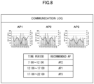
- the output processing portion 115 may output communication environment information corresponding to a plurality of access points AP and information of a recommended access point AP for each time period which is identified based on that communication environment information.
- FIG. 8 shows another example of the communication environment information.
- the output processing portion 115 causes a graph corresponding to each of the access points AP1, AP2, and AP3 to be displayed, and causes an access point AP having a good communication state to be displayed as a recommended access point AP for each time period. That is, the output processing portion 115 may output communication environment information including information of an access point AP suitable for the image forming apparatus 100 among a plurality of access points AP. This allows the user to grasp the suitable access point AP for each time period and thus set an access point AP appropriately.
- control portion 10 may store log information D2 of disconnection/reconnection in the storage portion 7.
- FIG. 9 shows an example of the log information D2.
- the log information D2 can suggest to the user whether or not a disconnection occurred frequently during the day and what the trend is in this case.
- the control portion 10 can present the log information D2 to the user by generating it and causing it to be displayed on the operation display portion 5, to be checked on the connected PC, or to be printed out as a report. For example, when the time of disconnection was during the daytime and during normal use, it is presumed that communication was not possible during that time. In this case, confirming the cause and taking measures to prevent recurrence can help to improve the communication environment thereafter.
Landscapes
- Engineering & Computer Science (AREA)
- Signal Processing (AREA)
- Multimedia (AREA)
- Computer Networks & Wireless Communication (AREA)
- Health & Medical Sciences (AREA)
- General Engineering & Computer Science (AREA)
- Biomedical Technology (AREA)
- General Health & Medical Sciences (AREA)
- Human Computer Interaction (AREA)
- Computer Security & Cryptography (AREA)
- Facsimiles In General (AREA)
- Accessory Devices And Overall Control Thereof (AREA)
- Mobile Radio Communication Systems (AREA)
Abstract
Description
- The present invention relates to an image processing apparatus and an image processing method.
- In recent years, an image forming apparatus equipped with a wireless LAN has been used. With the image forming apparatus, for example, a personal computer (PC) can wirelessly connect to the image forming apparatus via a predetermined access point (AP), and the image forming apparatus can perform printing processing or transfer image data scanned by the image forming apparatus to the PC.
- The image forming apparatus may experience slow communication speed or disconnection in an environment where many devices are connected by a wireless LAN or an environment where a device, such as a microwave oven, using radio waves in the same frequency band is placed nearby.
- Here, when the image forming apparatus is connected to a device by a wired LAN, a cable is used for the connection; therefore, when the connection between the devices is broken, it is possible to visually identify the cause such as a disconnected cable or a hub connecting the cable that is not turned on. In addition, when the communication speed is low, it is assumed that there are many PCs connected to the network or that the amount of communication data has temporarily increased, and the cause can be identified by capturing packets flowing through the cable.
- However, when the image forming apparatus is connected to a device by a wireless LAN, there may be an influence of radio wave strength or radio wave interference, and it is difficult to visually identify the cause of communication interference. Therefore, when the connection between the devices is broken, it is difficult to identify the cause. In addition, since the communication speed is affected by the magnitude of the radio wave strength, the amount of data flowing through the network, and the like, it is also difficult to identify the cause of a decrease in the communication speed.
- Conventionally, there has been known an image forming apparatus which notifies a user that the radio wave strength is not sufficient when the radio wave strength of a radio circuit becomes equal to or less than a predetermined threshold value (see, for example, Patent Literature 1).
- Patent Literature 1:
Japanese Unexamined Patent Application Publication No. 2019-179577 - However, in the conventional technique, only the result that the radio wave strength has become equal to or less than the threshold value is notified to the user, and the user cannot grasp the communication environment such as how the radio wave strength became equal to or less than the threshold value. Therefore, it is difficult for the user to implement measures for preventing the occurrence of a communication failure or improving the communication environment.
- An object of the present invention is to provide an image processing apparatus and an image processing method capable of presenting information relating to a communication environment to a user in an image processing apparatus connected to a device by a wireless LAN.
- An image processing apparatus according to one aspect of the present invention comprises a connection processing portion, a detection processing portion, a transmission/reception processing portion, and an output processing portion. The connection processing portion performs wireless connection to a predetermined access point. The detection processing portion detects the radio wave strength of the access point. The transmission/reception processing portion transmits and receives image data to and from a device connected to the access point. The output processing portion outputs communication environment information including the radio wave strength of the access point at the time of transmission and reception of the image data.
- An image processing method according to another aspect of the present invention includes a connection step, a detection step, a transmission/reception step, and an output step. In the connection step, wireless connection to a predetermined access point is performed. In the detection step, the radio wave strength of the access point is detected. In the transmission/reception step, image data is transmitted and received to and from a device connected to the access point. In the output step, communication environment information including the radio wave strength of the access point at the time of transmission and reception of the image data is output.
- According to the present invention, there are provided an image processing apparatus and an image processing method capable of presenting information relating to a communication environment to a user in an image processing apparatus connected to a device by a wireless LAN.
-
-
FIG. 1 is a schematic configuration diagram of an image forming apparatus according to an embodiment of the present invention. -
FIG. 2 is a functional block diagram of the image forming apparatus according to the embodiment of the present invention. -
FIG. 3 is a graph showing an example of the radio wave strength detected by the image forming apparatus according to the embodiment of the present invention. -
FIG. 4 shows an example of detection log information detected by the image forming apparatus according to the embodiment of the present invention. -
FIG. 5 is a graph showing the relationship between the number of packets and the radio wave strength detected by the image forming apparatus according to the embodiment of the present invention. -
FIG. 6 is a flowchart showing an example of the procedure of information presentation processing executed in the image forming apparatus according to the embodiment of the present invention. -
FIG. 7 shows an example of communication environment information output from the image forming apparatus according to the embodiment of the present invention. -
FIG. 8 shows an example of communication environment information output from the image forming apparatus according to the embodiment of the present invention. -
FIG. 9 shows log information of connections and disconnections detected in the image forming apparatus according to the embodiment of the present invention. - Embodiments of the present invention will be described below with reference to the accompanying drawings for understanding of the present invention. It is noted that the following embodiments are examples of embodying the present invention and do not limit the technical scope of the present invention.
- As shown in
FIG. 1 , animage forming apparatus 100 includes animage reading portion 1, an automatic document feeder (ADF) 2, animage forming portion 3, asheet feed portion 4, anoperation display portion 5, adischarge portion 6, a storage portion 7 (seeFIG. 2 ), a communication portion 8 (seeFIG. 2 ), acontrol portion 10, and the like. Theimage forming apparatus 100 is a multifunction peripheral having a plurality of functions such as a facsimile function for reading an image from a document sheet to obtain image data, a print function for forming an image based on image data, and a copy function. It is noted that theimage forming apparatus 100 may be a printer, a facsimile machine, a copier, or the like. Theimage forming apparatus 100 is an example of the image processing apparatus of the present invention. - The
communication portion 8 is a communication interface for wirelessly connecting theimage forming apparatus 100 to an access point AP connected to a network N1 and performing data communication according to a predetermined communication protocol with an external device, such as a personal computer (PC), via the access point AP. Thecommunication portion 8 is provided with a wireless LAN interface. - The access point AP is an IEEE802.11 (Wi-Fi) or other standard wireless LAN (Local Area Network) access point, a wireless LAN router, a wireless LAN-wired LAN network converter, a server with a built-in wireless LAN interface, or the like. The access point AP transmits a packet acquired from each device to the network N1, and causes a packet in the network N1 to be transmitted to each device. Thus, the access point AP can connect devices by causing the devices to perform packet communication with each other through a wireless LAN.
- In addition, the access point AP may be capable of transmitting an SSID (Service Set Identifier), which is the identification name (network name) of the access point in the wireless LAN (Wi-Fi), to each device.
- In the present embodiment, the network N1 is a wired LAN such as an intranet, the Internet, a WAN (Wide Area Network) such as a mobile phone network, or the like. When the network N1 is a WAN, the network N1 may be connectable to another server via a router, a gateway, or the like. In addition, the network N1 may constitute a VPN (Virtual Private Network).
-
FIG. 2 illustrates three access points AP1, AP2, and AP3. The access points AP1, AP2, and AP3 use, for example, the 2.4 GHz frequency band. In addition, in the example shown inFIG. 2 , the network N1 constitutes an internal LAN in a specific office, and a plurality of PCs (for example, PC1 and PC2) used by respective users are connected to the network N1. For example, a user A transfers image data from PC1 to theimage forming apparatus 100 via the access point AP1, and causes theimage forming apparatus 100 to execute printing processing. In addition, for example, a user B causes theimage forming apparatus 100 to scan an image and transfer the scanned image data to PC2 via the access point AP2. - Here, a user such as a network administrator can designate an access point AP to which the
image forming apparatus 100 is to be connected. For example, the user designates an access point AP suitable for transmission and reception (transfer processing) of image data based on the communication environment of theimage forming apparatus 100, and causes theimage forming apparatus 100 to connect to the access point AP.FIG. 3 is a graph showing the status of radio wave strength of each of the access points AP1, AP2, and AP3 detected in theimage forming apparatus 100. Although the details will be described later, the control portion 10 (detection processing portion 112) of theimage forming apparatus 100 can detect the radio wave strength of each of the access points AP1, AP2, and AP3 at the installation site of theimage forming apparatus 100. Theimage forming apparatus 100 detects the radio wave strengths of an access point AP used in each communication channel and a device (PC) connected to the access point AP. In addition, theimage forming apparatus 100 causes theoperation display portion 5 of theimage forming apparatus 100, the user's PC, or the like to display the graph shown inFIG. 3 as the detection result of the radio wave strengths. In addition, theimage forming apparatus 100 may print out the detection result as a report. This allows the user to grasp the number of devices using the wireless LAN and the radio wave strength of each device and each access point AP. - The user selects (designates) an access point AP to be used for transferring image data with reference to the detection result. The example shown in
FIG. 3 shows that the access point AP1 has the highest radio wave strength as the radio wave received by theimage forming apparatus 100, and that the number of devices connected to achannel 1 is small and the interference is relatively small. Therefore, the user can determine that the access point AP1 is the optimum access point AP to which theimage forming apparatus 100 is to be connected, and designate the access point AP1. - The control portion 10 (connection processing portion 111) of the
image forming apparatus 100 connects theimage forming apparatus 100 to the designated access point AP. In this way, theimage forming apparatus 100 can connect to the access point AP designated by the user. - The
image reading portion 1 includes a contact glass, a reading unit, a mirror, an optical lens, a CCD (Charge Coupled Device), and the like. - The
ADF 2 includes a document sheet loading portion, a plurality of conveying rollers, a document sheet holder, and a sheet discharge portion, and conveys a document sheet to be read by theimage reading portion 1. - The
image forming portion 3 can form an image on a sheet by an electrophotographic method based on image data obtained at theimage reading portion 1. In addition, theimage forming portion 3 can also form an image on a sheet based on image data input from an external device (for example, a user's PC). Specifically, theimage forming portion 3 includes a photoconductor drum, a charging device, a laser scanning unit (LSU), a developing device, a transfer roller, a cleaning device, a fixing roller, and a pressure roller. It is noted that theimage forming portion 3 may form an image on a sheet by another image forming method such as an inkjet method. In addition, theimage forming portion 3 conveys a sheet (printing sheet) on which an image has been formed to thedischarge portion 6. - The
sheet feed portion 4 includes asheet storing portion 41 and a plurality of conveying rollers, and supplies a sheet to theimage forming portion 3. Thesheet feed portion 4 is controlled by thecontrol portion 10 to convey a sheet stored in thesheet storing portion 41 to theimage forming portion 3. In addition, thesheet feed portion 4 includes amanual feed tray 42 on which a user manually (by a manual feed) sets a sheet. Thesheet feed portion 4 is controlled by thecontrol portion 10 to convey a sheet set on themanual feed tray 42 to theimage forming portion 3. In the present embodiment, thesheet storing portion 41 is provided on the lower side as viewed from the front of theimage forming apparatus 100, and themanual feed tray 42 is provided on the right side as viewed from the front of theimage forming apparatus 100. - The
discharge portion 6 discharges a printing sheet on which an image has been formed by theimage forming portion 3. Thedischarge portion 6 includes one ormore discharge trays 61. When a plurality ofdischarge trays 61 are provided, thedischarge trays 61 are provided at positions different in height from the installation surface (floor surface) of theimage forming apparatus 100. Thedischarge portion 6 is controlled by thecontrol portion 10 to discharge the printing sheet to apredetermined discharge tray 61. Thedischarge portion 6 discharges the printing sheet to adetermined discharge tray 61 in accordance with a command of thecontrol portion 10. In the present embodiment, thedischarge tray 61 is provided on the left side as viewed from the front of theimage forming apparatus 100. - The
operation display portion 5 includes a display portion such as a liquid crystal display for displaying various types of information in response to a command of thecontrol portion 10, and an operation portion such as an operation key or a touch panel for inputting various types of information to thecontrol portion 10 in response to a user's operation. - The
storage portion 7 is a nonvolatile storage device. For example, thestorage portion 7 is a storage device such as a nonvolatile memory including a flash memory, an EEPROM (registered trademark), and the like, an SSD, or an HDD. Thestorage portion 7 stores various control programs such as an information presentation program for causing thecontrol portion 10 to execute information presentation processing (seeFIG. 6 ) to be described later, various types of data, and the like. - The
control portion 10 includes control devices such as a CPU, a ROM, and a RAM. The CPU is a processor that executes various types of arithmetic processing. The ROM is a nonvolatile storage portion in which information such as control programs for causing the CPU to execute various types of processing are stored in advance. The RAM is a volatile or nonvolatile storage portion used as a temporary storage memory (work area) for various types of processing executed by the CPU. - Meanwhile, in the conventional technique, only the result that the radio wave strength has become equal to or less than the threshold value is notified to the user, and the user cannot grasp the communication environment such as how the radio wave strength became equal to or less than the threshold value. Therefore, it is difficult for the user to implement measures for preventing the occurrence of a communication failure or improving the communication environment. In contrast, the
image forming apparatus 100 according to the present embodiment can present information relating to the communication environment to the user. - Specifically, as shown in
FIG. 2 , thecontrol portion 10 includes various processing portions such as aconnection processing portion 111, adetection processing portion 112, a transmission/reception processing portion 113, adetermination processing portion 114, and anoutput processing portion 115. It is noted that thecontrol portion 10 functions as the various processing portions by executing various types of processing according to the information presentation program at the CPU. In addition, some or all of the processing portions included in thecontrol portion 10 may be constituted by electronic circuits. It is noted that the information presentation program may be a program for causing a plurality of processors to function as the various processing portions. - The
connection processing portion 111 wirelessly connects theimage forming apparatus 100 to a predetermined access point AP. For example, when the user designates a predetermined access point AP on a setting screen displayed on theoperation display portion 5 of theimage forming apparatus 100, theconnection processing portion 111 connects theimage forming apparatus 100 to the designated access point AP. When the connection between theimage forming apparatus 100 and the access point AP is established, data communication via the access point AP becomes possible between theimage forming apparatus 100 and a device connected to the network N1. As the connection method to the access point AP, a well-known technique can be applied. Theconnection processing portion 111 is an example of the connection processing portion of the present invention. - The
detection processing portion 112 detects the radio wave strength of an access point AP. For example, as described above, thedetection processing portion 112 detects the radio wave strength of each of a plurality of access points AP from which theimage forming apparatus 100 can receive radio waves (seeFIG. 3 ). - In addition, the
detection processing portion 112 detects the radio wave strength of a specific access point AP connected by theconnection processing portion 111. For example, when the power of theimage forming apparatus 100 is turned on and theimage forming apparatus 100 is connected to the designated access point AP, thedetection processing portion 112 starts detection processing of the radio wave strength of the access point AP. Thedetection processing portion 112 continues the detection processing until the connection between theimage forming apparatus 100 and the access point AP is interrupted (predetermined period). In addition, in the detection processing, thedetection processing portion 112 detects the radio wave strength when the transmission/reception processing portion 113 transmits and receives image data. That is, thedetection processing portion 112 detects the radio wave strength of the access point AP1 at the time of transmission and reception of the image data. Thedetection processing portion 112 stores the detection result of the predetermined period in thestorage portion 7. - It is noted that the user may be able to set the period during which the detection processing is executed in the
image forming apparatus 100. For example, the user may be able to set a start date and time and an end date and time of the detection processing on the setting screen. In this case, thedetection processing portion 112 executes the detection processing only for the period set by the user. - The transmission/
reception processing portion 113 transmits and receives image data to and from a device connected to the access point AP. Specifically, the transmission/reception processing portion 113 transmits and receives image data to and from a device (PC) connected to a specific access point AP connected by theconnection processing portion 111. For example, when theimage forming apparatus 100 is connected to the access point AP1 and image data for printing is output from PC1, the transmission/reception processing portion 113 receives the image data transferred from the access point AP1. When the transmission/reception processing portion 113 acquires the image data, theimage forming portion 3 forms an image on a sheet based on the image data. In addition, for example, when theimage forming apparatus 100 is connected to the access point AP1 and theimage forming apparatus 100 executes scanning processing of an image, the transmission/reception processing portion 113 outputs image data obtained by theimage reading portion 1 to the access point AP1. The access point AP1 transfers the received image data to PC2. - Here, the transmission/
reception processing portion 113 transmits and receives the image data by packet communication. In the packet communication, a transfer error may occur in which some packets of the image data are not transferred normally. Such a transfer error is likely to occur when the data amount of image data is large or when the communication environment is not good. - Therefore, in the present embodiment, the
determination processing portion 114 determines whether or not the image data has been transferred normally. Then, the transmission/reception processing portion 113 detects the data amount (for example, the number of packets) of the image data, the number of packets of the image data that have been transferred normally (normal transfer packets) (the number of normal transfer packets), and the number of packets of the image data that have not been transferred normally (error transfer packets) (the number of error transfer packets). The transmission/reception processing portion 113 stores these detection results in thestorage portion 7. - Here, the
control portion 10 generates detection log information D1 based on the detection result of thedetection processing portion 112 and the detection results of the transmission/reception processing portion 113, and stores the detection log information D1 in thestorage portion 7.FIG. 4 shows an example of the detection log information D1. The detection log information D1 includes information such as the number of normal transfer packets, the number of error transfer packets, and the radio wave strength for each set date and time. The set date and time is a date and time set in advance by the user, and is set, for example, at an hourly time (every hour on the hour) in the use time period in which theimage forming apparatus 100 is used. It is noted that the set date and time is not limited to every hour on the hour, and may be every two hours, every week, or every month. - The number of normal transfer packets is information calculated based on the normal transfer packets detected by the transmission/
reception processing portion 113. For example, thecontrol portion 10 registers, as the number of normal transfer packets, the number of packets obtained by adding up the normal transfer packets detected by the transmission/reception processing portion 113 every hour. The number of error transfer packets is information calculated based on the error transfer packets detected by the transmission/reception processing portion 113. For example, thecontrol portion 10 registers, as the number of error transfer packets, the number of packets obtained by adding up the error transfer packets detected by the transmission/reception processing portion 113 every hour. - The radio wave strength is information calculated based on the radio wave strength detected by the
detection processing portion 112. For example, thecontrol portion 10 registers, as the radio wave strength, an average value obtained by averaging the radio wave strengths detected by thedetection processing portion 112 at the time of transmission and reception of image data every hour. It is noted that thecontrol portion 10 may register, as the radio wave strength, the maximum value or the minimum value of the radio wave strength for each hour. - As described above, the
control portion 10 generates the detection log information D1 in association with the data amount of the image data (the number of normal transfer packets, the number of error transfer packets) and the radio wave strength. Thecontrol portion 10 registers each type of information in the detection log information D1, for example, every hour. - It is noted that
FIG. 4 shows detection log information D1 corresponding to a specific access point AP designated by the user. Here, when the user switches the access point AP to which theimage forming apparatus 100 is connected, thedetection processing portion 112 detects the radio wave strength of the switched access point AP, and the transmission/reception processing portion 113 transmits and receives image data via the switched access point AP. Then, thecontrol portion 10 generates detection log information D1 corresponding to the switched access point AP. Therefore, thestorage portion 7 stores detection log information D1 for each access point AP. For example, when theimage forming apparatus 100 has a record of using the access points AP1, AP2, and AP3, detection log information D1 corresponding to each of the access points AP1, AP2, and AP3 is stored in thestorage portion 7. - The
output processing portion 115 outputs communication environment information including the radio wave strength of the access point AP at the time of transmission and reception of the image data. The communication environment information is information used when the user selects an access point AP to which theimage forming apparatus 100 is to be connected, and the user can designate a specific access point AP by referring to the communication environment information. Theoutput processing portion 115 causes the communication environment information to be displayed on at least one of theimage forming apparatus 100 and the PC. - Specifically, the
output processing portion 115 outputs communication environment information in which the data amount (the number of packets) of the image data and the radio wave strength of the access point AP are associated with each other. In addition, theoutput processing portion 115 may further output a determination result as to whether or not image data has been transferred normally. For example, theoutput processing portion 115 outputs communication environment information in which the data amount of the image data, the radio wave strength of the access point AP, and the determination result (transfer success, transfer failure, etc.) are associated with each other. - In addition, for example, the
output processing portion 115 may output communication environment information in which the number of packets of the image data that have been transferred normally (the number of normal transfer packets), the number of packets of the image data that have not been transferred normally (the number of error transfer packets), and the radio wave strength of the access point AP are associated with each other. In addition, for example, theoutput processing portion 115 may output communication environment information indicating changes in the data amount of the image data and the radio wave strength of the access point AP during a predetermined period (for example, one day, one week, one month, etc.). Specifically, theoutput processing portion 115 presents the detection log information D1 (seeFIG. 4 ) generated by thecontrol portion 10 to the user. For example, theoutput processing portion 115 causes a predetermined PC or theoperation display portion 5 of theimage forming apparatus 100 to display the detection log information D1. The detection log information D1 is an example of the communication environment information of the present invention. - In addition, the
output processing portion 115 may present a graph corresponding to the detection log information D1 to the user so that the user can easily understand how the radio wave strength has changed.FIG. 5 shows an example of the graph generated by thecontrol portion 10 based on the detection log information D1. Thecontrol portion 10 generates detection log information D1 based on the detection results of thedetection processing portion 112 and the transmission/reception processing portion 113, and generates a graph based on the detection log information D1. The graph is an example of the communication environment information of the present invention. This allows the user to easily grasp the magnitude of the radio wave strength at the time of transmission and reception of the image data, the number of packets per hour, and how the number of packets and the radio wave strength change. - It is noted that when the user selects an access point AP and performs an operation to request communication environment information on the setting screen, the
output processing portion 115 presents the detection log information D1 corresponding to the access point AP (seeFIG. 4 ) or the graph (seeFIG. 5 ) to the user. In addition, theoutput processing portion 115 may output the communication environment information corresponding to a plurality of access points AP. In addition, theoutput processing portion 115 may print out the communication environment information (detection log information D1, the graph) in theimage forming apparatus 100. - An example of the procedure of information presentation processing executed by the
control portion 10 in theimage forming apparatus 100 will be described below with reference to the flowchart ofFIG. 6 . It is noted that the processing steps executed by thecontrol portion 10 will be referred to as steps S11, S12, .... It is noted that one or more steps included in the information presentation processing described here may be omitted as appropriate. In addition, the steps in the information presentation processing may be executed in a different order to the extent that they produce similar effects. Furthermore, although the case in which the steps in the information presentation processing are executed by thecontrol portion 10 of theimage forming apparatus 100 is described here as an example, in other embodiments, the steps in the information presentation processing may be executed by a plurality of other processors in a distributed manner. - Here, the present invention can be understood as an invention of an information presentation method for executing one or more steps included in the information presentation processing. The information presentation method is an example of the image processing method of the present invention.
- First, in step S11, the
control portion 10 receives an operation for designating an access point AP from a user (for example, a network administrator). For example, when the user selects, on the setting screen, one access point AP from a list of access points AP from which theimage forming apparatus 100 can receive radio waves, thecontrol portion 10 acquires identification information of the access point AP. - Next, in step S12, the
control portion 10 executes connection processing for connecting theimage forming apparatus 100 to the designated access point AP. When the connection between theimage forming apparatus 100 and the access point AP is established, data communication via the access point AP becomes possible between theimage forming apparatus 100 and a device connected to the network N1. Step S12 is an example of the connection step of the present invention. - Next, in step S13, the
control portion 10 starts detection processing of the radio wave strength of the access point AP connected to theimage forming apparatus 100. For example, thecontrol portion 10 detects the radio wave strength at a predetermined sampling period. Thecontrol portion 10 stores the detection result in thestorage portion 7. Step S13 is an example of the detection step of the present invention. - Next, in step S14, the
control portion 10 determines whether or not image data has been transmitted or received. When thecontrol portion 10 determines that image data has been transmitted or received (Yes in S14), the processing proceeds to step S15. In addition, when image data has been transmitted or received, thecontrol portion 10 detects the radio wave strength of the access point AP at the time of transmission or reception of the image data. Thecontrol portion 10 stores the radio wave strength detected at the time of transmission or reception of the image data in thestorage portion 7. When thecontrol portion 10 does not determine that image data has been transmitted or received (No in S14), the processing proceeds to step S17. Step S14 is an example of the transmission/reception step of the present invention. - In step S15, the
control portion 10 determines whether or not the image data has been transferred normally (success or failure). Thecontrol portion 10 determines the success or failure of the transfer of the image data based on the number of packets of the image data. - Next, in step S16, the
control portion 10 detects the number of normal transfer packets and the number of error transfer packets of the image data based on the determination result in step S15. - Next, in step S17, the
control portion 10 generates detection log information D1 (seeFIG. 4 ) based on the radio wave strength at the time of transmission or reception of the image data and the number of normal transfer packets and the number of error transfer packets of the image data, and stores the detection log information D1 in thestorage portion 7. It is noted that when thecontrol portion 10 does not determine that the image data has been transmitted or received in step S14 (No in S14), thecontrol portion 10 registers the radio wave strength corresponding to the set time in the detection log information D1. - Next, in step S18, the
control portion 10 determines whether or not a request for presentation of communication environment information has been received from the user. When thecontrol portion 10 has received the presentation request from the user (Yes in S18), the processing proceeds to step S19. On the other hand, when thecontrol portion 10 has not received the presentation request from the user (No in S18), the processing returns to step S13. Returning to step S13, thecontrol portion 10 repeats the processing described above. - Next, in step S19, the
control portion 10 presents the communication environment information to the user. For example, thecontrol portion 10 causes the user's PC or theoperation display portion 5 of theimage forming apparatus 100 to display the detection log information D1 (seeFIG. 4 ). In addition, thecontrol portion 10 may cause the user's PC or theoperation display portion 5 of theimage forming apparatus 100 to display the graph (seeFIG. 5 ) generated based on the detection log information D1. In addition, thecontrol portion 10 may cause theimage forming apparatus 100 to print out the communication environment information (detection log information D1, the graph) as a report. Step S19 is an example of the output step of the present invention. - The
control portion 10 executes the information presentation processing as described above. Thecontrol portion 10 executes the information presentation processing every time an access point AP is designated by the user. - As described above, the
image forming apparatus 100 according to the present embodiment wirelessly connects to a predetermined access point AP, and outputs communication environment information including the radio wave strength of the access point AP at the time of transmission or reception of image data transmitted or received via the access point AP. Specifically, theimage forming apparatus 100 presents to the user communication environment information in which the number of normal transfer packets, the number of error transfer packets, and the radio wave strength of the access point in a predetermined period are associated with each other. This makes it possible to present useful information relating to the communication environment of theimage forming apparatus 100 to the user. Therefore, the user can easily grasp the communication environment corresponding to theimage forming apparatus 100. In addition, based on the information (communication environment information), the user can take measures to prevent the occurrence of a communication failure or to improve the communication environment. - For example, according to the graph shown in
FIG. 5 , it can be seen at a glance that the radio wave strength is weak and the number of error transfer packets is large from 14:00 to 15:00. From this, it can be inferred that there was some change that caused radio interference during this time period. Therefore, by identifying and remedying the cause of radio interference, the user can prevent future communication failures and continue comfortable wireless communication. - The present invention is not limited to the above-described embodiment. As another embodiment of the present invention, the
output processing portion 115 may output communication environment information in which the data amount of the image data (the number of normal transfer packets, the number of error transfer packets), the radio wave strength of the access point AP, and information indicating the communication state of the access point AP (good, bad, etc.) are associated with each other.FIG. 7 shows another example of the communication environment information. As shown inFIG. 7 , information indicating the communication state of the access point AP1 is displayed for each time period. This allows the user to easily grasp the communication state. - In addition, as another embodiment of the present invention, the
output processing portion 115 may output communication environment information corresponding to a plurality of access points AP and information of a recommended access point AP for each time period which is identified based on that communication environment information.FIG. 8 shows another example of the communication environment information. As shown inFIG. 8 , theoutput processing portion 115 causes a graph corresponding to each of the access points AP1, AP2, and AP3 to be displayed, and causes an access point AP having a good communication state to be displayed as a recommended access point AP for each time period. That is, theoutput processing portion 115 may output communication environment information including information of an access point AP suitable for theimage forming apparatus 100 among a plurality of access points AP. This allows the user to grasp the suitable access point AP for each time period and thus set an access point AP appropriately. - When the connection between the access point AP and the
image forming apparatus 100 is broken due to some kind of failure, communication between the two becomes impossible; however, when a function to recover from the disconnected state is set in theimage forming apparatus 100, it is difficult for the user to recognize that the communication has been disconnected. Therefore, as another embodiment, thecontrol portion 10 may store log information D2 of disconnection/reconnection in thestorage portion 7.FIG. 9 shows an example of the log information D2. - The log information D2 can suggest to the user whether or not a disconnection occurred frequently during the day and what the trend is in this case. The
control portion 10 can present the log information D2 to the user by generating it and causing it to be displayed on theoperation display portion 5, to be checked on the connected PC, or to be printed out as a report. For example, when the time of disconnection was during the daytime and during normal use, it is presumed that communication was not possible during that time. In this case, confirming the cause and taking measures to prevent recurrence can help to improve the communication environment thereafter. - It is to be understood that the embodiments described herein are illustrative only and non-limiting, as the scope of the present invention is defined by the appended claims, not by the detailed description preceding the claims. Accordingly, all modifications or equivalents that do not depart from the scope of the claims are included in the claims.
Claims (9)
- An image processing apparatus comprising:a connection processing portion for performing wireless connection to a predetermined access point;a detection processing portion for detecting a radio wave strength of the access point;a transmission/reception processing portion for transmitting and receiving image data to and from a device connected to the access point; andan output processing portion for outputting communication environment information including a radio wave strength of the access point at a time of transmission and reception of the image data.
- The image processing apparatus according to claim 1, wherein the output processing portion outputs the communication environment information in which a data amount of the image data and the radio wave strength of the access point are associated with each other.
- The image processing apparatus according to claim 1, further comprising:a determination processing portion for determining whether or not the image data has been transferred normally, whereinthe output processing portion outputs the communication environment information in which a data amount of the image data, the radio wave strength of the access point, and a determination result by the determination processing portion are associated with each other.
- The image processing apparatus according to claim 1, further comprising:a determination processing portion for determining whether or not the image data has been transferred normally, whereinthe output processing portion outputs the communication environment information in which a number of packets of the image data that have been transferred normally, a number of packets of the image data that has not been transferred normally, and the radio wave strength of the access point are associated with each other.
- The image processing apparatus according to claim 1, wherein the output processing portion outputs the communication environment information indicating changes in a data amount of the image data and in the radio wave strength of the access point during a predetermined period.
- The image processing apparatus according to claim 1, wherein the output processing portion outputs the communication environment information corresponding to each of a plurality of the access points.
- The image processing apparatus according to claim 1, wherein the output processing portion outputs the communication environment information including information of an access point suitable for the image processing apparatus among a plurality of the access points.
- The image processing apparatus according to claim 1, wherein the output processing portion causes the image processing apparatus to print out the communication environment information.
- An image processing method comprising:a connection step of performing wirelessly connection to a predetermined access point;a detection step of detecting a radio wave strength of the access point;a transmission/reception step of transmitting and receiving image data to and from a device connected to the access point; andan output step of outputting communication environment information including a radio wave strength of the access point at a time of transmission and reception of the image data.
Applications Claiming Priority (2)
| Application Number | Priority Date | Filing Date | Title |
|---|---|---|---|
| JP2020114724 | 2020-07-02 | ||
| PCT/JP2021/025069 WO2022004869A1 (en) | 2020-07-02 | 2021-07-02 | Image processing device and image processing method |
Publications (3)
| Publication Number | Publication Date |
|---|---|
| EP4178124A1 true EP4178124A1 (en) | 2023-05-10 |
| EP4178124A4 EP4178124A4 (en) | 2023-12-20 |
| EP4178124B1 EP4178124B1 (en) | 2026-03-18 |
Family
ID=79316446
Family Applications (1)
| Application Number | Title | Priority Date | Filing Date |
|---|---|---|---|
| EP21831594.3A Active EP4178124B1 (en) | 2020-07-02 | 2021-07-02 | Image processing device and image processing method |
Country Status (5)
| Country | Link |
|---|---|
| US (1) | US20230262185A1 (en) |
| EP (1) | EP4178124B1 (en) |
| JP (1) | JP7409507B2 (en) |
| CN (1) | CN115735338A (en) |
| WO (1) | WO2022004869A1 (en) |
Family Cites Families (30)
| Publication number | Priority date | Publication date | Assignee | Title |
|---|---|---|---|---|
| JP2003169188A (en) * | 2001-12-04 | 2003-06-13 | Murata Mach Ltd | Facsimile machine |
| US20040102192A1 (en) | 2002-11-26 | 2004-05-27 | Texas Instruments Incorporated | Method and system for discovery and display of operating wireless networks |
| JP3826934B2 (en) * | 2003-12-04 | 2006-09-27 | コニカミノルタビジネステクノロジーズ株式会社 | Image forming apparatus, image forming system, image forming method, image forming control program, and computer-readable recording medium recording image forming control program |
| JP4302617B2 (en) * | 2004-12-13 | 2009-07-29 | インターナショナル・ビジネス・マシーンズ・コーポレーション | Wireless station |
| JP2007011819A (en) * | 2005-07-01 | 2007-01-18 | Canon Inc | Print control device |
| US20070041036A1 (en) * | 2005-08-18 | 2007-02-22 | Kabushiki Kaisha Toshiba | Image forming apparatus |
| US8769127B2 (en) * | 2006-02-10 | 2014-07-01 | Northrop Grumman Systems Corporation | Cross-domain solution (CDS) collaborate-access-browse (CAB) and assured file transfer (AFT) |
| JP2007276119A (en) * | 2006-04-03 | 2007-10-25 | Seiko Epson Corp | Avoiding errors in printing devices |
| US20080089225A1 (en) * | 2006-10-12 | 2008-04-17 | Felix Ammay | Methods, systems, and computer program products for generating network outage reports |
| KR100816560B1 (en) * | 2006-12-05 | 2008-03-25 | 한국정보보호진흥원 | Deputy Certification Method for Mobile Multicast Broadcast Security |
| US7962155B2 (en) * | 2007-07-18 | 2011-06-14 | Hewlett-Packard Development Company, L.P. | Location awareness of devices |
| JP2009093223A (en) * | 2007-10-03 | 2009-04-30 | Fuji Xerox Co Ltd | Data processor, image forming system and data processing program |
| JP5811748B2 (en) * | 2011-09-30 | 2015-11-11 | ブラザー工業株式会社 | Printing device |
| US9203713B2 (en) * | 2012-03-02 | 2015-12-01 | Payoda Inc. | System and method for creating and establishing a workflow based template for a domain server or IP server in datacenters |
| US8767695B2 (en) * | 2012-06-27 | 2014-07-01 | Google Inc. | Measurement-based network selection |
| EP2786618B1 (en) * | 2012-08-21 | 2016-02-10 | Unify GmbH & Co. KG | Method and apparatus for selecting an access point based on direction of movement |
| JP5694263B2 (en) * | 2012-09-26 | 2015-04-01 | 京セラドキュメントソリューションズ株式会社 | Image processing system, image processing method, and image processing apparatus |
| JP2014072817A (en) * | 2012-10-01 | 2014-04-21 | Hitachi Ltd | Wireless communication method, tracking area management device, and mobility management device |
| JP6119431B2 (en) * | 2013-05-31 | 2017-04-26 | ブラザー工業株式会社 | Wireless communication apparatus and wireless communication method |
| JP2015115925A (en) * | 2013-12-16 | 2015-06-22 | 船井電機株式会社 | Printer and printing system |
| JP2016174295A (en) * | 2015-03-17 | 2016-09-29 | セイコーエプソン株式会社 | Radio communication apparatus and radio communication apparatus control method |
| JP6477158B2 (en) * | 2015-03-31 | 2019-03-06 | ブラザー工業株式会社 | Display control apparatus, display control method, and storage medium |
| JP6444263B2 (en) * | 2015-05-27 | 2018-12-26 | クラリオン株式会社 | Content distribution system and content distribution method |
| CN108476423A (en) * | 2015-12-30 | 2018-08-31 | T移动美国公司 | Use the dynamic user experience quality contextual analysis of equipment |
| JP6765827B2 (en) * | 2016-03-11 | 2020-10-07 | キヤノン株式会社 | Image processing system, image processing device, its control method and program |
| JP6656112B2 (en) * | 2016-07-28 | 2020-03-04 | シャープ株式会社 | Printing system, image forming apparatus, printing method, and communication method |
| JP2018137657A (en) * | 2017-02-23 | 2018-08-30 | セイコーエプソン株式会社 | Printing apparatus and printing apparatus control method |
| JP6494704B2 (en) * | 2017-08-09 | 2019-04-03 | キヤノン株式会社 | COMMUNICATION DEVICE, ITS CONTROL METHOD, AND PROGRAM |
| JP7271868B2 (en) * | 2018-06-13 | 2023-05-12 | セイコーエプソン株式会社 | Information processing equipment |
| JP6865789B2 (en) | 2019-06-27 | 2021-04-28 | シャープ株式会社 | Image forming devices, terminal devices, and image forming systems, and computer programs |
-
2021
- 2021-07-02 EP EP21831594.3A patent/EP4178124B1/en active Active
- 2021-07-02 CN CN202180045716.1A patent/CN115735338A/en active Pending
- 2021-07-02 JP JP2022534120A patent/JP7409507B2/en active Active
- 2021-07-02 WO PCT/JP2021/025069 patent/WO2022004869A1/en not_active Ceased
- 2021-07-02 US US18/013,376 patent/US20230262185A1/en not_active Abandoned
Also Published As
| Publication number | Publication date |
|---|---|
| WO2022004869A1 (en) | 2022-01-06 |
| JPWO2022004869A1 (en) | 2022-01-06 |
| EP4178124A4 (en) | 2023-12-20 |
| US20230262185A1 (en) | 2023-08-17 |
| CN115735338A (en) | 2023-03-03 |
| JP7409507B2 (en) | 2024-01-09 |
| EP4178124B1 (en) | 2026-03-18 |
Similar Documents
| Publication | Publication Date | Title |
|---|---|---|
| US9729747B2 (en) | Information processing device, and method for instructing job to image processing apparatus | |
| US20180284678A1 (en) | Image forming apparatus, image forming method | |
| US11126125B1 (en) | Image forming apparatus | |
| US9584675B2 (en) | Image processing apparatus, communication condition setting method | |
| CN107534921B (en) | Electronic device and radio wave setting method | |
| EP4178124B1 (en) | Image processing device and image processing method | |
| US20180213039A1 (en) | Information processing apparatus and communication system | |
| US20150131115A1 (en) | Image forming apparatus, image forming system, and image forming method | |
| US10038817B2 (en) | Image forming apparatus | |
| JP6007775B2 (en) | Job management apparatus, network system, image processing apparatus, job management method, and job management program | |
| US11497080B2 (en) | Wireless communication apparatus and wireless communication method | |
| CN103685828B (en) | Image processing system, image processing method and image processing apparatus | |
| US9531898B2 (en) | Image forming apparatus | |
| US20160241725A1 (en) | Communication apparatus, method of controlling communication apparatus, and storage medium | |
| JP6076384B2 (en) | Facsimile apparatus and image forming apparatus having the same | |
| US10534807B2 (en) | Information processing apparatus for notifying planned use time and control method of information processing apparatus for notifying planned use time | |
| JP6477862B2 (en) | Image processing apparatus and communication method | |
| JP6542684B2 (en) | INFORMATION PROCESSING SYSTEM, IMAGE FORMING APPARATUS, TRANSFER CONTROL PROGRAM, AND TRANSFER CONTROL METHOD | |
| JP4963428B2 (en) | Wireless communication system and method for controlling wireless communication apparatus in wireless communication system | |
| JP6711321B2 (en) | Facsimile transmission system and image forming apparatus | |
| JP4062099B2 (en) | Operation terminal device | |
| JP6199832B2 (en) | Image processing system, image processing apparatus, portable terminal, and job execution method | |
| JP2015043525A (en) | Communication device | |
| JP2008065650A (en) | Communication equipment, program, and communication method | |
| JP2016019275A (en) | Facsimile apparatus and facsimile communication system |
Legal Events
| Date | Code | Title | Description |
|---|---|---|---|
| STAA | Information on the status of an ep patent application or granted ep patent |
Free format text: STATUS: THE INTERNATIONAL PUBLICATION HAS BEEN MADE |
|
| PUAI | Public reference made under article 153(3) epc to a published international application that has entered the european phase |
Free format text: ORIGINAL CODE: 0009012 |
|
| STAA | Information on the status of an ep patent application or granted ep patent |
Free format text: STATUS: REQUEST FOR EXAMINATION WAS MADE |
|
| 17P | Request for examination filed |
Effective date: 20221228 |
|
| AK | Designated contracting states |
Kind code of ref document: A1 Designated state(s): AL AT BE BG CH CY CZ DE DK EE ES FI FR GB GR HR HU IE IS IT LI LT LU LV MC MK MT NL NO PL PT RO RS SE SI SK SM TR |
|
| DAV | Request for validation of the european patent (deleted) | ||
| DAX | Request for extension of the european patent (deleted) | ||
| A4 | Supplementary search report drawn up and despatched |
Effective date: 20231120 |
|
| RIC1 | Information provided on ipc code assigned before grant |
Ipc: G06F 3/12 20060101ALI20231114BHEP Ipc: B41J 29/42 20060101ALI20231114BHEP Ipc: B41J 29/38 20060101ALI20231114BHEP Ipc: B41J 29/00 20060101ALI20231114BHEP Ipc: H04W 48/16 20090101ALI20231114BHEP Ipc: H04N 1/00 20060101ALI20231114BHEP Ipc: H04B 17/309 20150101ALI20231114BHEP Ipc: H04B 17/23 20150101AFI20231114BHEP |
|
| STAA | Information on the status of an ep patent application or granted ep patent |
Free format text: STATUS: EXAMINATION IS IN PROGRESS |
|
| 17Q | First examination report despatched |
Effective date: 20250212 |
|
| GRAP | Despatch of communication of intention to grant a patent |
Free format text: ORIGINAL CODE: EPIDOSNIGR1 |
|
| STAA | Information on the status of an ep patent application or granted ep patent |
Free format text: STATUS: GRANT OF PATENT IS INTENDED |
|
| INTG | Intention to grant announced |
Effective date: 20251024 |
|
| GRAS | Grant fee paid |
Free format text: ORIGINAL CODE: EPIDOSNIGR3 |
|
| GRAA | (expected) grant |
Free format text: ORIGINAL CODE: 0009210 |
|
| STAA | Information on the status of an ep patent application or granted ep patent |
Free format text: STATUS: THE PATENT HAS BEEN GRANTED |
|
| AK | Designated contracting states |
Kind code of ref document: B1 Designated state(s): AL AT BE BG CH CY CZ DE DK EE ES FI FR GB GR HR HU IE IS IT LI LT LU LV MC MK MT NL NO PL PT RO RS SE SI SK SM TR |
|
| REG | Reference to a national code |
Ref country code: CH Ref legal event code: F10 Free format text: ST27 STATUS EVENT CODE: U-0-0-F10-F00 (AS PROVIDED BY THE NATIONAL OFFICE) Effective date: 20260318 Ref country code: GB Ref legal event code: FG4D |
|
| REG | Reference to a national code |
Ref country code: IE Ref legal event code: FG4D |
|
| REG | Reference to a national code |
Ref country code: DE Ref legal event code: R096 Ref document number: 602021050290 Country of ref document: DE |
|
| PG25 | Lapsed in a contracting state [announced via postgrant information from national office to epo] |
Ref country code: RS Free format text: LAPSE BECAUSE OF FAILURE TO SUBMIT A TRANSLATION OF THE DESCRIPTION OR TO PAY THE FEE WITHIN THE PRESCRIBED TIME-LIMIT Effective date: 20260618 |
|
| PG25 | Lapsed in a contracting state [announced via postgrant information from national office to epo] |
Ref country code: GR Free format text: LAPSE BECAUSE OF FAILURE TO SUBMIT A TRANSLATION OF THE DESCRIPTION OR TO PAY THE FEE WITHIN THE PRESCRIBED TIME-LIMIT Effective date: 20260619 |
|
| REG | Reference to a national code |
Ref country code: LT Ref legal event code: MG9D |
|
| PG25 | Lapsed in a contracting state [announced via postgrant information from national office to epo] |
Ref country code: LT Free format text: LAPSE BECAUSE OF FAILURE TO SUBMIT A TRANSLATION OF THE DESCRIPTION OR TO PAY THE FEE WITHIN THE PRESCRIBED TIME-LIMIT Effective date: 20260318 |
|
| PG25 | Lapsed in a contracting state [announced via postgrant information from national office to epo] |
Ref country code: NO Free format text: LAPSE BECAUSE OF FAILURE TO SUBMIT A TRANSLATION OF THE DESCRIPTION OR TO PAY THE FEE WITHIN THE PRESCRIBED TIME-LIMIT Effective date: 20260618 |
|
| PG25 | Lapsed in a contracting state [announced via postgrant information from national office to epo] |
Ref country code: SE Free format text: LAPSE BECAUSE OF FAILURE TO SUBMIT A TRANSLATION OF THE DESCRIPTION OR TO PAY THE FEE WITHIN THE PRESCRIBED TIME-LIMIT Effective date: 20260318 Ref country code: FI Free format text: LAPSE BECAUSE OF FAILURE TO SUBMIT A TRANSLATION OF THE DESCRIPTION OR TO PAY THE FEE WITHIN THE PRESCRIBED TIME-LIMIT Effective date: 20260318 |
|
| PG25 | Lapsed in a contracting state [announced via postgrant information from national office to epo] |
Ref country code: HR Free format text: LAPSE BECAUSE OF FAILURE TO SUBMIT A TRANSLATION OF THE DESCRIPTION OR TO PAY THE FEE WITHIN THE PRESCRIBED TIME-LIMIT Effective date: 20260318 |
|
| REG | Reference to a national code |
Ref country code: NL Ref legal event code: MP Effective date: 20260318 |
|
| PG25 | Lapsed in a contracting state [announced via postgrant information from national office to epo] |
Ref country code: LV Free format text: LAPSE BECAUSE OF FAILURE TO SUBMIT A TRANSLATION OF THE DESCRIPTION OR TO PAY THE FEE WITHIN THE PRESCRIBED TIME-LIMIT Effective date: 20260318 |
|
| PG25 | Lapsed in a contracting state [announced via postgrant information from national office to epo] |
Ref country code: BG Free format text: LAPSE BECAUSE OF FAILURE TO SUBMIT A TRANSLATION OF THE DESCRIPTION OR TO PAY THE FEE WITHIN THE PRESCRIBED TIME-LIMIT Effective date: 20260318 |