EP4178106B1 - Universelle endklemme zur sicherung von solarpaneelen an einer schienentrageführung - Google Patents
Universelle endklemme zur sicherung von solarpaneelen an einer schienentrageführung Download PDFInfo
- Publication number
- EP4178106B1 EP4178106B1 EP22205326.6A EP22205326A EP4178106B1 EP 4178106 B1 EP4178106 B1 EP 4178106B1 EP 22205326 A EP22205326 A EP 22205326A EP 4178106 B1 EP4178106 B1 EP 4178106B1
- Authority
- EP
- European Patent Office
- Prior art keywords
- solar panel
- clamp
- washer
- rail guide
- channel
- Prior art date
- Legal status (The legal status is an assumption and is not a legal conclusion. Google has not performed a legal analysis and makes no representation as to the accuracy of the status listed.)
- Active
Links
Images


Classifications
-
- H—ELECTRICITY
- H01—ELECTRIC ELEMENTS
- H01R—ELECTRICALLY-CONDUCTIVE CONNECTIONS; STRUCTURAL ASSOCIATIONS OF A PLURALITY OF MUTUALLY-INSULATED ELECTRICAL CONNECTING ELEMENTS; COUPLING DEVICES; CURRENT COLLECTORS
- H01R4/00—Electrically-conductive connections between two or more conductive members in direct contact, i.e. touching one another; Means for effecting or maintaining such contact; Electrically-conductive connections having two or more spaced connecting locations for conductors and using contact members penetrating insulation
- H01R4/24—Connections using contact members penetrating or cutting insulation or cable strands
-
- H—ELECTRICITY
- H01—ELECTRIC ELEMENTS
- H01R—ELECTRICALLY-CONDUCTIVE CONNECTIONS; STRUCTURAL ASSOCIATIONS OF A PLURALITY OF MUTUALLY-INSULATED ELECTRICAL CONNECTING ELEMENTS; COUPLING DEVICES; CURRENT COLLECTORS
- H01R4/00—Electrically-conductive connections between two or more conductive members in direct contact, i.e. touching one another; Means for effecting or maintaining such contact; Electrically-conductive connections having two or more spaced connecting locations for conductors and using contact members penetrating insulation
- H01R4/28—Clamped connections, spring connections
- H01R4/30—Clamped connections, spring connections utilising a screw or nut clamping member
- H01R4/308—Conductive members located parallel to axis of screw
-
- H—ELECTRICITY
- H02—GENERATION; CONVERSION OR DISTRIBUTION OF ELECTRIC POWER
- H02S—GENERATION OF ELECTRIC POWER BY CONVERSION OF INFRARED RADIATION, VISIBLE LIGHT OR ULTRAVIOLET LIGHT, e.g. USING PHOTOVOLTAIC [PV] MODULES
- H02S10/00—PV power plants; Combinations of PV energy systems with other systems for the generation of electric power
- H02S10/10—PV power plants; Combinations of PV energy systems with other systems for the generation of electric power including a supplementary source of electric power, e.g. hybrid diesel-PV energy systems
- H02S10/12—Hybrid wind-PV energy systems
-
- H—ELECTRICITY
- H02—GENERATION; CONVERSION OR DISTRIBUTION OF ELECTRIC POWER
- H02S—GENERATION OF ELECTRIC POWER BY CONVERSION OF INFRARED RADIATION, VISIBLE LIGHT OR ULTRAVIOLET LIGHT, e.g. USING PHOTOVOLTAIC [PV] MODULES
- H02S30/00—Structural details of PV modules other than those related to light conversion
-
- Y—GENERAL TAGGING OF NEW TECHNOLOGICAL DEVELOPMENTS; GENERAL TAGGING OF CROSS-SECTIONAL TECHNOLOGIES SPANNING OVER SEVERAL SECTIONS OF THE IPC; TECHNICAL SUBJECTS COVERED BY FORMER USPC CROSS-REFERENCE ART COLLECTIONS [XRACs] AND DIGESTS
- Y02—TECHNOLOGIES OR APPLICATIONS FOR MITIGATION OR ADAPTATION AGAINST CLIMATE CHANGE
- Y02B—CLIMATE CHANGE MITIGATION TECHNOLOGIES RELATED TO BUILDINGS, e.g. HOUSING, HOUSE APPLIANCES OR RELATED END-USER APPLICATIONS
- Y02B10/00—Integration of renewable energy sources in buildings
- Y02B10/10—Photovoltaic [PV]
-
- Y—GENERAL TAGGING OF NEW TECHNOLOGICAL DEVELOPMENTS; GENERAL TAGGING OF CROSS-SECTIONAL TECHNOLOGIES SPANNING OVER SEVERAL SECTIONS OF THE IPC; TECHNICAL SUBJECTS COVERED BY FORMER USPC CROSS-REFERENCE ART COLLECTIONS [XRACs] AND DIGESTS
- Y02—TECHNOLOGIES OR APPLICATIONS FOR MITIGATION OR ADAPTATION AGAINST CLIMATE CHANGE
- Y02E—REDUCTION OF GREENHOUSE GAS [GHG] EMISSIONS, RELATED TO ENERGY GENERATION, TRANSMISSION OR DISTRIBUTION
- Y02E10/00—Energy generation through renewable energy sources
- Y02E10/50—Photovoltaic [PV] energy
Definitions
- the present invention relates generally to providing an apparatus for securing a solar panel module to a solar panel rail guide support structure. More specifically, the invention relates to providing an end clamp that mounts a bottom flange of a solar panel module to a solar panel rail guide support structure. The end clamp does not require any tools for insertion. It mechanically fastens and electrically bonds the solar panel module to the solar panel rail guide support structure. Exemplary embodiments for both a single and dual-handle structure are disclosed.
- One method that solar panel modules may be secured to a residential roof structure is by providing parallel rows of rail guides that are secured to the roof. Solar panel modules are then placed on top of the array of rail guides, and are then mechanically coupled to the top of the rail guides.
- end clamps and mid-clamps One of the limitations of using end clamps and mid-clamps is that it can be time-consuming to align the clamps between the slots in the rail guides with the top surfaces of the solar panel modules. Another limitation is that in order to tighten the end clamps and mid-clamps, additional tools are typically required. Since standard end clamps are external to an array, placed on the outside of the solar panel module, they require additional length of rail to be secured beyond the module frame. This results in extra segments of rails that protrude from the array as well as hardware that is visible from a distance.
- the present invention overcomes these limitations and offers a solution that provides an easy-to-use clamp that can secure and electrically bond a solar panel module to a rail guide, without using additional tools, and all while hiding the clamp from plain view of the solar panel array making it more aesthetically pleasing to anyone viewing the solar panel array on a given roof.
- the apparatus is also simple to manufacture.
- the present invention offers a dual-handle version of the same apparatus that enables a user additional flexibility in securing a solar panel module to a rail guide from either side of a rail guide.
- the assembly comprise a clamp with front and rear ends, with a channel in the front end that houses a post structure with a shaft between a top and bottom washer on each side of the post structure and a spring coupled between the two end washers, such that the spring rests between a base of the channel and the top washer.
- the bottom washer is configured to fit within, and move along, a channel of the solar panel rail guide.
- the bottom washer comprises at least one serration on its top surface configured to penetrate the surface layer of a solar panel rail guide channel.
- the bottom surface of the clamp comprises at least one raised portion that extends downward from the surface of the clamp and is configured to penetrate the surface layer of a solar panel.
- top washer is coupled to the shaft and is configured to compress the spring when the rear end of the handle is moved to a locked position.
- each raised portion may be removed from the clamp.
- the spring comprises. one or more disc springs configured to create a clamping force when compressed and provide flexibility to accommodate various module frame geometries.
- rear end of the handle is configured to provide tactile feedback when the handle is moved into a locked position, and when the bottom washer is within a top channel of a solar panel rail guide.
- the clamp may also comprise a first and second handle each extending outward from the front end, each of the first and second handles further comprising a rear end.
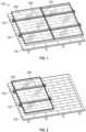
- FIG. 1 One method that solar panel modules may be secured to a residential roof structure is shown in Fig. 1 .
- a solar panel array configuration 100 is shown installed on roof 105.
- the solar panel array includes several solar panel modules 400 that are arranged and secured to several rail guides 300 that are arranged in a parallel fashion across the roof 105.
- the rail guides 300 are coupled to roof attachments 140.
- the solar panel modules 400 are then secured to the roof attachments 140 by using end clamps 130 and mid-clamps 120.
- the end clamps 130 and mid-clamps 120 provide a means to electrically couple the rail guide 300 to the solar panel modules 400 throughout the entire array 100.
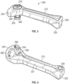
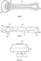
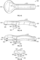
- Fig. 3 shows a front perspective view of an exemplary universal end clamp 200.
- the clamp 200 is generally in the shape of a handle 210 that extends from the front end 240 to the back end 220.
- the front end 240 is generally round, but can be other suitable shapes as long as it can cover a portion of a bottom flange 420 of a solar panel module as shown in Figs. 21 and 22 .
- the bottom of the front end 240 includes a channel 242.
- the channel 242 includes a base 243 as shown in Figs. 5 and 7 .
- a post structure 262 fits within the channel 242 at a sufficient distance from the edge of the front end 240, typically in its center, to allow the front end 240 to cover a sufficient portion of the bottom flange 420 when it is in the locked position shown in Figs. 20-22 .
- the post structure 262 comprises a bottom washer 250 and a shaft 265 that extends upward along and is secured by a top washer 270, typically at a threaded end of the shaft 265.
- the bottom washer 250 typically has a diameter that is larger than the shaft 265 includes one or more serrations 260.
- Fig. 4 shows a bottom perspective view of the clamp 200.
- the bottom of the backend typically tapers toward a level that includes an extension 230.
- the bottom surface of the front end 240 is typically at a lower plane than the extension 230. This enables the handle 200 to snap or lock into place on the top channel 310 of the mounting rail 300 when the handle is rotated into a locked position as shown below in Figs. 20-22 and will be discussed further below.
- the bottom of the front end 240 includes at least one raised portion such as a bonding pin 280 so that the surface of the bonding pin 280 extends outward from the bottom surface of the front end 240.
- the bottom washer 250 also includes an optional tool feature 255 for assembly to the top washer 270.
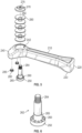
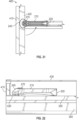
- Fig. 5 illustrates an exploded view of the channel 242 and the front and 240.
- Bonding pins 280 may be separate pins as shown or any component coupled to the clamp body and including sharp features intended to create an electrical bonding path. They may be positioned, press-fit (as shown), or may include threaded portion to be screwed into a female threaded portion on the bottom surface of the front end 240 although any suitable manner of connecting the bonding pins 280 is acceptable. Their design and orientation may also provide resistance to lateral forces, keeping the module from sliding under loading.
- Figs. 5 and 6 show the details of the post structure 262.
- the post structure 262 shows the shaft 265 extending upward from the bottom washer 250.
- the post At the end opposite the bottom washer 250, the post includes a male threaded portion 264 for coupling to the female threaded portion 275 of the top washer 270 by rotating the top washer 270 or the post structure 262 into a tightened position.
- the post structure 262 may also include a series of disc springs 290 or washers are shown stacked in a configuration to create a spring force and deflection range.
- Each of the springs 290 is in the shape of a cone with a central opening 292. When assembled, the springs 290 are placed against each other so that the tapered central opening 292 of the first spring 290 faces up and is coupled to the second spring 290 with the tapered central opening facing down.
- disc springs 290 are used in this exemplary embodiment, other types of springs, more or less disc springs like washers such as Belleville washers, or disc springs in different configurations (stacked, alternating, or both) can create a different spring force or different deflection range. This allows for the clamp to fit on different frame thicknesses
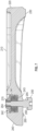
- Fig. 7 shows a cross-sectional side view of the clamp 200.
- the shaft 265 is inserted through the channel 242 and through the central openings 292 of the springs 290 so that the male threaded portion 264 can be rotatably coupled to the female threaded portion 275 of the top washer 270.
- the springs 290 rest on the channel base 243 and compress the washers 292 forming a spring function as the top washer 275 is tightened or lowered along the shaft 265 of the post structure 262.
- the extension 230 on the backend 220 is positioned slightly lower than the bottom surface of the front end 240.
- Figures 8, 9, 10 , and 11 show top, side, front, and bottom-perspective views respectively of the clamp 200.
- Figures 12-23 show the steps of using the clamp 200.
- Figs. 12 and 13 show a front perspective view and a top view respectively of the clamp 200 before it is engaged with a typical solar panel rail guide 300.
- the rail guide 300 is typically made of an electrically conducting material that has a surface oxidation layer and is connected to a roof attachment 140 on its lower end 330 so the rail guide 300 is secured lengthwise across a roof as shown in Figs. 1 and 2 .
- the top of the rail guide 300 includes two side flanges 320 that form a slot or top channel 310.
- the bottom washer 250 of the clamp 200 is first inserted into the opening of the top channel 310 of the rail guide 300 as shown in Figs. 14 and 15 .
- the bottom washer 250 should be of a suitable width/diameter so that it can freely move along the slot 310, and the shaft 265 should be of a suitable width/diameter so that it is less than the width of the top channel 310, but greater than the width of the opening formed along the two side flanges 320 so that it can both freely move through the top channel 310 and engage the bottom surface of the two side flanges 320.
- an exemplary solar panel module 400 is positioned perpendicularly on the top of the side flanges 320 of the rail guide 300 as shown in Fig. 16.
- Fig. 16 illustrates a front perspective view with a transparent view of the rear wall 410
- Fig. 17 illustrates a top view of the image in Fig. 16 showing the solar panel module 400 that further comprises a bottom flange 420 and the top panel 430 (shown in Fig.
- the bottom flange 420 typically comprises an electrically conducting material with a surface oxidation layer.
- a locked position which is the position when the entire length of the clamp 200 rests directly over the top of the side flanges 320 on rail guide 300 on top of the side flanges 320.
- the clamp 200 may be rotated in either direction.
- Ramps 221 and 222 on the underside of the clamp 200 and back end 220 respectively can make the rotation easier.
- a side view of the images in Figs. 20 and 21 is shown in Fig. 22 . In Fig. 22 , one can see that the extension 230 is at a lower planar level than the bottom surface of the front end 240.
- Fig. 23 illustrates a top perspective view of a solar panel module 400 being secured by multiple clamps 200 across a pair of rail guides 300.
- FIG. 29-32 A more detailed illustration of the front end of the assembly is shown in Figs. 29-32 that demonstrates what occurs when the rear end 220 of the clamp 200 is rotated into the locked position as shown in Fig. 22 .
- Figs. 29 and 30 show a cross section of the front end 240 after the clamp 200 is rotated into the locked position on thin ( Fig. 29 ) and thick ( Fig. 30 ) module flanges 420.
- the bottom washer 250 rests in the top channel 310
- the bottom surface of the front end is engaged with the bottom flange 420, and the springs 290 are partially compressed.
- Fig. 30 shows what occurs when the module flange 420 is thicker.
- the springs 290 compress to a more flattened position allowing the front end to move upward to accommodate the thicker flange 420.
- the serrations 260 of the bottom washer 250 penetrate the oxidation layer on the bottom surfaces of the side flanges 320 and electrically bond the bottom washer 250 to the rail guide 300 as shown in further detail in Fig. 31 .
- the bonding pins 280 on the bottom surface of the front end 240 penetrate the oxidation layer of the bottom flange 420 and electrically bond the clamp 200 to the solar panel module 400 as shown in further detail in Fig. 32 .
- the compression of the springs 290 along the post structure 262 can be adjusted by rotating the top washer 270 clockwise along the threaded portion 264 of the shaft 265. They can also be locked into position in manufacturing so that the installer never has to adjust anything.
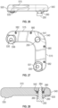
- FIG. 24-42 An alternate exemplary embodiment of the clamp 200 is shown in Figs. 24-42 .
- a dual-handle clamp 500 is shown.
- the dual-handle clamp 500 has similar characteristics of the clamp 200.
- the clamp 500 shaped generally like a boomerang with first and second handles 510 and 515 extending outward from a front end 540 that forms a corner of the clamp 500 at approximately 90 -degree angles from each other.
- the first handle 510 has a back end 520, and the second handle 515 has a back end 525.
- Handles 510 and 515 are identical, but with mirrored features across line A-A in Fig 25 .
- the front end 540 includes a channel 542 (shown in Fig. 29 ) that is identical to the channel 242.
- the same post structure 262 used in clamp 200 is connected to the top washer 270 through the channel 542 as shown and is assembled using the same optional springs 290 to form a spring structure through the channel 542 as that used in the channel 242 of the clamp 200 as shown in Fig. 28 , which illustrates how the post structure 262, the top washer 270, and the springs 290 are assembled in the channel 542.
- the back end 525 further includes an extension 530 that extends downward from the bottom of the rear end.
- the front end 540 in this exemplary embodiment is beveled slightly upward so that it will fit over the bottom flange 420 of the solar panel module 400.
- the back end 525 of the first handle 510 also includes an extension 530, as does the back end 520 of the second handle 515 with an extension 535.
- These extensions 530 and 535 extend downward and allow each of the back ends 520 and 525 to snap onto the top channel 320 of the rail guide 300. Ramps 531 and 536 near the extensions 530 and 535 can make the rotation easier.
- bonding pins 580 and 582 are also secured to the bottom surface of the clamp 500.
- two bonding pins 580 are shown at the front end 540 of the clamp 500, and two bonding pins 582 toward the rear of the handles 510 and 515 respectively, but generally, at least one bonding pin 580 is secured to each handle 510 and 515 just as described for the front end 240 of the clamp 200.
- the bonding pins 580 and 582 are typically located along the edge of the bottom surface of the clamp 500.
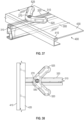
- Figures 33-42 show the steps of using the clamp 500.
- Figs. 33 and 34 show a front perspective view and a top view respectively of the clamp 500 before it is engaged with the solar panel rail guide 300. The steps are the same as those used to secure clamp 200 to the rail guide 300.
- the bottom washer 250 of the clamp 500 is first inserted into the front opening 305 of the top channel 310 of the rail guide 300 as shown in Figs. 35 and 36 .
- the first handle 510 and second handle 515 should generally face away from the front opening 305 as illustrated.
- Fig. 37 illustrates a front perspective view with a transparent view of the rear wall 410
- Fig. 38 illustrates a top view of the image in Fig. 37 showing the solar panel module 400 that further comprises a bottom flange 420 and the top panel 430 (shown in Fig. 23 ).
- either the back end 520 on the first handle 510, or the back end 525 of the second handle 520 of the clamp 500 is rotated to a locked position, which is when the entire length of either the first handle 510 or the second handle 520 of the clamp 500 rests directly over the top of the side flanges 320 on rail guide 300.
- a locked position which is when the entire length of either the first handle 510 or the second handle 520 of the clamp 500 rests directly over the top of the side flanges 320 on rail guide 300.
- the extensions 530 and 535 are at a lower planar level than the bottom surface of the front end 540. This enables the extensions 530 and 535 to snap into place and create a downward compression force on the bottom surface of the front end 540 and either of the back ends 520 or 525 of the clamp 500.
- the snap also provides tactile feedback to the installer that the clamp 500 is secured.
- the compression force at the front end 540 firmly engages the bottom surface with the bottom flange 420 securing it in place when either the extension 530 or 535 are firmly engaged on top of the side flanges 320.
- the clamp 500 can be rotated in either direction.
- a difference between the install of the single-handle clamp 200 vs. the dual-handle clamp 500 is that the single-handle generally involves a pushing action to move the clamp 200 into the locked position, and the dual-handle clamp 500 generally involves a pulling action to move it into a locked position.
- Multiple clamps 500 can be assembled similar to the clamps 200 shown in Fig. 23 , which illustrates a top perspective view of a solar panel module 400 being secured by multiple clamps 200 across a pair of rail guides 300.
- FIG. 29-32a A detailed illustration of the front end of the assembly is shown in Figs. 29-32a that demonstrates what occurs when either of the back ends 520 or 525 of the clamp 500 is rotated into the locked position as shown in Figs. 41 and 42 .
- the steps and results of the rotation to the locked position are very similar to what occurs when the clamp 200 is rotated to the locked position.
- Figs. 29 and 30 show a cross section of the front end 540, which has essentially the same structure as the front end 240 of clamp 200, before and after the clamp 500 is rotated into the locked position. As shown in Fig.
- Fig. 30 shows what occurs on a thicker flange 420.
- the springs 290 compress to a more flattened position while the spring force resists and pulls the front end 540 upward to accommodate the thicker flange 420.
- the serrations 260 of the bottom washer 250 penetrate the oxidation layer on the bottom surfaces of the side flanges 320 and electrically bond the bottom washer 250 to the rail guide 300 as shown in further detail in Fig. 31 .
- the bonding pins 580 on the bottom surface of either handle 510 or 515 penetrate the oxidation layer of the bottom flange 420 and electrically bond the clamp 500 to the solar panel module 400 as shown in further detail in Fig. 32 and Fig. 32a .
- the bonding pins 582 on either handle 510 or 515 may also penetrate the top surface of the side flanges 320 to provide additional electrical bonding.
- the compression of the springs 290 along the post structure 262 can be adjusted by rotating the top washer 270 clockwise along the threaded portion 264 of the shaft 265. or secured in manufacturing to simplify the process for the installer.
- Fig. 43 illustrates a top view of a universal end clamp 600, which is an alternate exemplary embodiment of the clamp 200.
- the clamp 600 comprises handle 610 with back end 620, and front end 640.
- the front end 640 is generally curved, but can be of other suitable shapes as well.
- a top end 670 of a post structure 662 is shown, although the top end 670 does not have to be visible along the top surface of the clamp 600.
- a shaft 665 typically extends upward from the top surface of the bottom washer 650 and is coupled to the clamp 600 at top end 670.
- the post structure 662 can be coupled in any suitable manner such as using a threaded top end into a threaded opening on the bottom of the clamp 600, or it can be molded as part of the clamp 600.
- Figs. 45-46 illustrate other views of the clamp 600.
- the post structure 662 does not include a spring structure like that in clamp 200.
- the bottom washer 650 rests in the top channel 310, the bottom surface of the front end is engaged with the bottom flange 420, and the serrations 660 of the bottom washer 650 penetrate the oxidation layer on the bottom surfaces of the side flanges 320 and electrically bond the bottom washer 650 to the rail guide 300 as shown in further detail in Fig. 31 .
- the clamp no tool is required to install the clamp and secure the solar panel module to the solar panel rail guide.
- the design allows the array to be installed so that the rails are flush with the sides of the solar panel modules and the hardware hidden from plain view within the array.
- the mounting rail ends can also be cut straight or jagged. The rail ends can also extend past the edge of the solar panel module or not quite reach the module. In either case, the clamp would not be affected.
Landscapes
- Life Sciences & Earth Sciences (AREA)
- Engineering & Computer Science (AREA)
- Sustainable Development (AREA)
- Sustainable Energy (AREA)
- Roof Covering Using Slabs Or Stiff Sheets (AREA)
- Photovoltaic Devices (AREA)
Claims (16)
- Klemme (200, 500, 600) zum Verbinden und elektrischen Kontaktieren eines Solarmoduls mit einer Solarmodulschienenführung, umfassend:A. einen Griff (210, 510, 515, 610), umfassend:i. ein vorderes Ende (240, 540, 640) undii. mindestens ein hinteres Ende (220, 520, 525, 620),iii. wobei das vordere Ende (240, 540, 640) einen Kanal (242, 542) umfasst, der sich zwischen einer oberen Fläche und einer unteren Fläche des vorderen Endes (240, 540, 640) erstreckt, wobei der Kanal (242, 542) eine Basis (243) umfasst; undiv. mindestens einen erhöhten Abschnitt (280, 580, 680), der sich von der unteren Fläche des vorderen Endes (240, 540, 640) nach unten erstreckt und dazu konfiguriert ist, eine Oberflächenschicht des Solarmoduls zu durchdringen, um eine elektrische Verbindung zwischen der Klemme (200) und dem Solarmodul bereitzustellen; undB. eine Pfostenstruktur (262, 662), umfassend:i. eine untere Unterlegscheibe (250, 650), ferner umfassend eine Verzahnung (260, 660), die sich von einer oberen Fläche auf der unteren Unterlegscheibe (250, 650) nach oben erstreckt;ii. eine Welle (265, 665), die sich von der unteren Unterlegscheibe (250, 650) durch den Kanal nach oben erstreckt;wobei die Pfostenstruktur (262, 662) eine Feder umfasst, die zwischen der oberen Unterlegscheibe (270) und der Basis (243) des Kanals (242, 542) gekoppelt ist;wobei der Kanal (242, 542) die Pfostenstruktur (262, 662) aufnimmt und wobei die Verzahnung (260, 660) zu der unteren Fläche des vorderen Endes hin ausgerichtet und dazu konfiguriert ist, eine Oberflächenschicht der Solarmodulschienenführung zu durchdringen, um eine elektrische Verbindung zwischen der Solarmodulschienenführung und der Klemme bereitzustellen, sodass eine elektrische Erdung zwischen der Solarmodulschienenführung, der Klemme (200) und dem Solarmodul bereitgestellt wird.
- Klemme (200, 500, 600) nach Anspruch 1, wobei die radiale Verlängerung an dem unteren Ende der Pfostenstruktur (262, 662) entfernbar oder dauerhaft an der unteren Unterlegscheibe (250, 650) befestigt ist.
- Klemme (200, 500, 600) nach Anspruch 1, wobei das obere Ende der Pfostenstruktur (262, 662) ferner eine obere Unterlegscheibe (270) umfasst, wobei die Pfostenstruktur (262, 662) dazu konfiguriert ist, mit der oberen Unterlegscheibe (270) gekoppelt zu sein, wobei die obere Unterlegscheibe (270) vorzugsweise mit der Welle gekoppelt ist.
- Klemme (200, 500, 600) nach Anspruch 3, wobei die obere Unterlegscheibe (270) dazu konfiguriert ist, die Feder zu komprimieren, wenn das hintere Ende (220, 520, 525, 620) des Griffs (210, 510, 515, 610) in eine verriegelte Position bewegt wird.
- Klemme (200, 500, 600) nach Anspruch 1, wobei die Feder mindestens ein Lager umfasst, das dazu konfiguriert ist, beim Komprimieren eine Klemmkraft zu erzeugen.
- Klemme (200, 500, 600) nach Anspruch 5, wobei das Lager eine Tellerfeder (290) oder eine Unterlegscheibe umfasst.
- Klemme (200, 500, 600) nach Anspruch 1, wobei das hintere Ende (220, 520, 525, 620) des Griffs (210, 510, 515, 610) dazu konfiguriert ist, eine taktile Rückmeldung beim Bewegen in eine verriegelte Position bereitzustellen.
- Klemme (200, 500, 600) nach Anspruch 1, wobei der erhöhte Abschnitt (280, 580, 680) eine Vielzahl von abnehmbaren Verbindungsstiften umfasst.
- Anordnung, umfassend:A. ein Solarmodul (400), umfassend einen unteren Flansch (420);B. eine Solarmodulschienenführung (300), umfassend Seitenflansche (320), die einen oberen Kanal (310) bilden; undC. eine Klemme (200, 500, 600), umfassend:C.1. einen Griff (210, 510, 515, 610), umfassend:i. ein vorderes Ende (240, 540, 640) undii. mindestens ein hinteres Ende (220, 520, 525, 620),iii. wobei das vordere Ende (240, 540, 640) einen Kanal (242, 542) umfasst, der sich zwischen einer oberen Fläche und einer unteren Fläche des vorderen Endes (240, 540, 640) erstreckt, wobei der Kanal (242, 542) eine Basis (243) umfasst; undiv. mindestens einen erhöhten Abschnitt (280, 580, 680), der sich von der unteren Fläche des vorderen Endes (240, 540, 640) nach unten erstreckt und dazu konfiguriert ist, eine Oberflächenschicht des Solarmoduls zu durchdringen, um eine elektrische Verbindung zwischen der Klemme (200, 500, 600) und dem Solarmodul (400) bereitzustellen; undC.2. eine Pfostenstruktur (262, 662), umfassend:i. eine untere Unterlegscheibe (250, 650), ferner umfassend eine Verzahnung (260, 660), die sich von einer oberen Fläche auf der unteren Unterlegscheibe nach oben erstreckt;ii. eine Welle (265, 665), die sich von der unteren Unterlegscheibe (250, 650) durch den Kanal nach oben erstreckt;iii. eine obere Unterlegscheibe (270), die an die Welle gekoppelt ist;wobei die Pfostenstruktur (262, 662) eine Feder umfasst, die zwischen der oberen Unterlegscheibe (270) und der Basis (243) des Kanals (242, 542) gekoppelt ist;D. wobei das Solarmodul (400) oben auf den Seitenflanschen der Solarmodulschienenführung (300) positioniert ist und die Pfostenstruktur (262, 662) in dem oberen Kanal (310) der Solarmodulschienenführung (300) positioniert ist; undE. wobei die Verzahnung (260, 660) in den oberen Kanal (310) eingreift, um die Klemme (200, 500, 600) mit der Solarmodulschienenführung (300) elektrisch zu verbinden, und der erhöhte Abschnitt (280, 580, 680) in den unteren Flansch (420) des Solarmoduls eingreift, um die Klemme (200, 500, 600) mit dem Solarmodul (400) elektrisch zu verbinden.
- Anordnung nach Anspruch 9, wobei die radiale Verlängerung (250, 650) an dem unteren Ende der Pfostenstruktur (262, 662) entfernbar oder dauerhaft an der unteren Unterlegscheibe befestigt ist.
- Anordnung nach Anspruch 9, wobei der erhöhte Abschnitt (280, 580, 680) eine Vielzahl von abnehmbaren Verbindungsstiften umfasst.
- Anordnung nach Anspruch 9, wobei die Solarmodulschienenführung (300) ein elektrisch leitendes Material umfasst und ferner eine Oberflächenoxidationsschicht auf den Seitenflanschen (320) umfasst.
- Anordnung nach Anspruch 9, wobei die Solarmodulschienenführung (300) ferner eine Oberflächenoxidationsschicht umfasst, sodass die Verzahnung die Oberflächenoxidationsschicht beim Bewegen des hinteren Endes des Griffs (210, 510, 515, 610) in eine verriegelte Position durchdringt.
- Anordnung nach Anspruch 9, wobei der untere Flansch (420) des Solarmoduls (400) teilweise von dem vorderen Ende (240, 540, 640) des Griffs (210, 510, 515, 610) bedeckt ist, wenn dieser über dem unteren Flansch (420) des Solarmoduls (400) positioniert ist.
- Anordnung nach Anspruch 9, wobei der untere Flansch (420) des Solarmoduls (400) ein elektrisch leitendes Material ist, das ferner eine Oberflächenoxidationsschicht umfasst.
- Anordnung nach Anspruch 9, wobei der erhöhte Abschnitt (280, 580, 680) die Oberflächenoxidationsschicht des unteren Flansches der Solarmodulschienenführung (300) beim Bewegen des hinteren Endes (220, 520, 525, 620) des Griffs (210, 510, 515, 610) in die verriegelte Position durchdringt.
Applications Claiming Priority (3)
| Application Number | Priority Date | Filing Date | Title |
|---|---|---|---|
| US201662432433P | 2016-12-09 | 2016-12-09 | |
| PCT/US2017/065285 WO2018107014A1 (en) | 2016-12-09 | 2017-12-08 | Universal end clamp for securing solar panels to a rail support guide |
| EP17879648.8A EP3552307B1 (de) | 2016-12-09 | 2017-12-08 | Universelle endklemme zur sicherung von solarpaneelen an einer schienentrageführung |
Related Parent Applications (2)
| Application Number | Title | Priority Date | Filing Date |
|---|---|---|---|
| EP17879648.8A Division EP3552307B1 (de) | 2016-12-09 | 2017-12-08 | Universelle endklemme zur sicherung von solarpaneelen an einer schienentrageführung |
| EP17879648.8A Division-Into EP3552307B1 (de) | 2016-12-09 | 2017-12-08 | Universelle endklemme zur sicherung von solarpaneelen an einer schienentrageführung |
Publications (3)
| Publication Number | Publication Date |
|---|---|
| EP4178106A1 EP4178106A1 (de) | 2023-05-10 |
| EP4178106B1 true EP4178106B1 (de) | 2025-02-19 |
| EP4178106C0 EP4178106C0 (de) | 2025-02-19 |
Family
ID=62491404
Family Applications (2)
| Application Number | Title | Priority Date | Filing Date |
|---|---|---|---|
| EP22205326.6A Active EP4178106B1 (de) | 2016-12-09 | 2017-12-08 | Universelle endklemme zur sicherung von solarpaneelen an einer schienentrageführung |
| EP17879648.8A Active EP3552307B1 (de) | 2016-12-09 | 2017-12-08 | Universelle endklemme zur sicherung von solarpaneelen an einer schienentrageführung |
Family Applications After (1)
| Application Number | Title | Priority Date | Filing Date |
|---|---|---|---|
| EP17879648.8A Active EP3552307B1 (de) | 2016-12-09 | 2017-12-08 | Universelle endklemme zur sicherung von solarpaneelen an einer schienentrageführung |
Country Status (7)
| Country | Link |
|---|---|
| US (2) | US10673151B2 (de) |
| EP (2) | EP4178106B1 (de) |
| BR (1) | BR112019010845B1 (de) |
| ES (1) | ES3022132T3 (de) |
| MX (1) | MX2019006706A (de) |
| PL (1) | PL3552307T3 (de) |
| WO (1) | WO2018107014A1 (de) |
Families Citing this family (23)
| Publication number | Priority date | Publication date | Assignee | Title |
|---|---|---|---|---|
| US9611652B2 (en) | 2011-02-25 | 2017-04-04 | Dustin M. M. Haddock | Mounting device for building surfaces having elongated mounting slot |
| US20130168525A1 (en) | 2011-12-29 | 2013-07-04 | Dustin M.M. Haddock | Mounting device for nail strip panels |
| US10443896B2 (en) | 2016-07-29 | 2019-10-15 | Rmh Tech Llc | Trapezoidal rib mounting bracket with flexible legs |
| WO2018081722A1 (en) | 2016-10-31 | 2018-05-03 | Haddock Dustin M M | Metal panel electrical bonding clip |
| AU2018348090B2 (en) | 2017-10-09 | 2021-11-18 | Rmh Tech Llc | Rail assembly with invertible side-mount adapter for direct and indirect mounting applications |
| EP3769017A4 (de) | 2018-03-21 | 2021-12-08 | RMH Tech LLC | Pv-modul-montageanordnung mit klemm-/abstandsanordnung |
| WO2019191691A1 (en) * | 2018-03-30 | 2019-10-03 | Sunpower Corporation | Single-walled connecting key framesets |
| US20210391821A1 (en) * | 2018-10-23 | 2021-12-16 | Pv Solutions, Llc | Devices, methods, and systems for installation of photovoltaic systems |
| WO2020124011A1 (en) | 2018-12-14 | 2020-06-18 | Rmh Tech Llc | Mounting device for nail strip panels |
| AU2021239839B2 (en) | 2020-03-16 | 2024-12-19 | Rmh Tech Llc | Mounting device for a metal roof |
| US11041310B1 (en) | 2020-03-17 | 2021-06-22 | Rmh Tech Llc | Mounting device for controlling uplift of a metal roof |
| BR112023000401A2 (pt) | 2020-07-09 | 2023-01-31 | Rmh Tech Llc | Sistema, dispositivo e método de montagem |
| US12009777B2 (en) | 2021-04-01 | 2024-06-11 | Kloeckner Metals Corporation | Solar panel rail |
| EP4393057A4 (de) | 2021-08-24 | 2025-05-14 | IronRidge, Inc. | Schienenbasiertes solarpaneelmontagesystem |
| WO2023039155A1 (en) | 2021-09-09 | 2023-03-16 | Rmh Tech Llc | Torque actuated rail assembly |
| KR20250034133A (ko) | 2022-07-06 | 2025-03-10 | 알엠에이치 테크 엘엘씨 | 클램프/스탠드오프 장치를 갖는 pv 모듈 장착 어셈블리 |
| USD1075493S1 (en) | 2022-07-06 | 2025-05-20 | Rmh Tech Llc | Clamp for a photovoltaic module mounting assembly |
| USD1113406S1 (en) | 2023-04-14 | 2026-02-17 | Rmh Tech Llc | Mounting device |
| CN121358993A (zh) | 2023-04-14 | 2026-01-16 | Rmh技术有限责任公司 | 用于金属面板的安装装置 |
| USD1109686S1 (en) | 2023-08-10 | 2026-01-20 | Rmh Tech Llc | Mount for a component of a photovoltaic assembly |
| USD1091448S1 (en) | 2023-10-10 | 2025-09-02 | Bluescope Buildings North America, Inc. | Solar panel frame bracket |
| US12057801B1 (en) | 2023-12-29 | 2024-08-06 | Sunmodo Corporation | Devices and systems for mounting solar panels to metal roofs |
| USD1109069S1 (en) * | 2024-01-18 | 2026-01-13 | Jing-Xin Solar Ltd. | End clamp for solar panel |
Family Cites Families (39)
| Publication number | Priority date | Publication date | Assignee | Title |
|---|---|---|---|---|
| DE202006018586U1 (de) * | 2006-12-06 | 2007-03-08 | Kaack, Peter | Anordnung zum Montieren von Solarmodulen |
| US8938919B2 (en) * | 2007-09-21 | 2015-01-27 | Andalay Solar, Inc. | Electrical connectors for solar modules |
| NL2001200C2 (nl) * | 2008-01-18 | 2009-07-21 | Walraven Holding Bv J Van | Bevestiging voor zonnepanelen. |
| US8413391B2 (en) * | 2008-10-13 | 2013-04-09 | Sunlink Corporation | Solar array mounting system with universal clamp |
| US10277159B2 (en) * | 2008-11-17 | 2019-04-30 | Kbfx Llc | Finished multi-sensor units |
| DE102008064554A1 (de) | 2008-12-23 | 2010-07-01 | Ulrich, Siegfried, Dipl.-Ing | Befestigungssystem für Solarmodule |
| DE202009001810U1 (de) * | 2009-02-06 | 2009-04-16 | K2 Systems Gmbh | Solarmodulbefestigung |
| CN101626037B (zh) | 2009-07-03 | 2012-05-30 | 伍文享 | 一种太阳能面板框架的安装系统装置 |
| US8869216B2 (en) * | 2009-12-14 | 2014-10-21 | Lg Electronics Inc. | Method of processing non-real time service and broadcast receiver |
| US20110214365A1 (en) * | 2010-03-08 | 2011-09-08 | JAC-Rack, Inc. | Apparatus and method for securing solar panel cells to a support frame |
| WO2012031286A2 (en) | 2010-09-03 | 2012-03-08 | Solar Liberty Energy Systems, Inc. | Solar panel racking assembly |
| CA2816562A1 (en) * | 2010-10-05 | 2012-04-12 | Dynoraxx, Inc. | Mount for pitched roof and method of use |
| FR2969744B1 (fr) | 2010-12-22 | 2013-02-08 | Vincent Ind | Element et methode de fixation d'au moins un panneau photovoltaique sur un rail et installation comprenant au moins un tel element |
| DE102011010832A1 (de) | 2011-02-02 | 2012-08-02 | Siegfried Ulrich | Befestigung für Sonnenkollektoren |
| US8745935B2 (en) * | 2011-10-14 | 2014-06-10 | A. Raymond Et Cie | Photovoltaic panel fastening system |
| US9698724B2 (en) * | 2011-12-13 | 2017-07-04 | Solarcity Corporation | Connecting components for photovoltaic arrays |
| US10686401B2 (en) * | 2012-07-05 | 2020-06-16 | Ironridge, Inc. | Apparatus for securing and covering a clamping device for solar panel modules |
| US10256766B2 (en) * | 2012-10-01 | 2019-04-09 | Marc M. Thomas | Solar panel installation and dimension compensating retention device |
| US9644864B2 (en) * | 2013-03-07 | 2017-05-09 | Thomas Mark Hoffmann | Solar oven positioning |
| US9057545B2 (en) | 2013-05-16 | 2015-06-16 | Kevin Stapleton | Solar panel roof mounting bracket and related methods |
| DE102013009834A1 (de) | 2013-06-07 | 2014-12-11 | Siegfried Ulrich | Befestigungssystem für Solarmodule |
| DE202013005668U1 (de) | 2013-06-18 | 2014-09-23 | Mounting Systems Gmbh | Universeller Endhalter zur Halterung von Solarmodulen |
| US9825581B2 (en) * | 2013-11-14 | 2017-11-21 | Ecolibrium Solar, Inc. | Modular sloped roof solar mounting system |
| US8957302B1 (en) | 2014-05-12 | 2015-02-17 | Zep Solar Llc | Solar photovoltaic module clamping system |
| US9647433B2 (en) * | 2014-11-19 | 2017-05-09 | Ironridge, Inc. | Rail-less solar panel assembly and installation method |
| US20160190975A1 (en) * | 2014-12-31 | 2016-06-30 | Sundance Renewable Solutions | Clamp assembly for securing panels to substrates |
| US10027276B2 (en) * | 2015-01-30 | 2018-07-17 | Solarcity Corporation | Photovoltaic mounting system |
| US10756668B2 (en) * | 2015-03-11 | 2020-08-25 | Ecouni, Llc | Universal sloped roof solar panel mounting system |
| US20160285408A1 (en) * | 2015-03-25 | 2016-09-29 | Ironridge, Inc. | Clamp for securing and electrically bonding solar panels to a rail support |
| US9671136B2 (en) * | 2015-03-25 | 2017-06-06 | Ironridge, Inc. | Clamp for securing and electrically bonding solar panels to a rail support |
| CN104980094B (zh) * | 2015-07-01 | 2017-09-05 | 江苏晨科新能源有限公司 | 太阳能支架导轨及其配合使用的卡块、中压块和侧压块 |
| US9837954B2 (en) * | 2015-08-31 | 2017-12-05 | Ironridge, Inc. | Electrical bonding splice for solar panel rail guides |
| GB2545938B (en) * | 2016-02-03 | 2018-12-12 | Intuitive Designs Jersey Ltd | Modular solar-energy and rainwater collection apparatus |
| US10298170B2 (en) * | 2016-03-14 | 2019-05-21 | Solarcity Corporation | Photovoltaic mounting system |
| US10852038B2 (en) * | 2016-04-13 | 2020-12-01 | Elie Rothschild | Bonding jumper clip for solar panels |
| US10312855B2 (en) * | 2016-05-31 | 2019-06-04 | Ironridge, Inc. | Bracket mount for securing micro-inverters and power optimizers to solar panel arrays |
| CN120270425A (zh) * | 2016-06-30 | 2025-07-08 | 京洛株式会社 | 浮板、浮板集合体以及浮板集合体的设置方法 |
| WO2018013494A2 (en) * | 2016-07-10 | 2018-01-18 | Solar Connections International, Inc. | Solar panel mounting clamp and system |
| WO2019006357A2 (en) * | 2017-06-29 | 2019-01-03 | Tessolar Incorporated | SYSTEM AND METHOD FOR MOUNTING PHOTOVOLTAIC MODULE |
-
2017
- 2017-12-08 EP EP22205326.6A patent/EP4178106B1/de active Active
- 2017-12-08 EP EP17879648.8A patent/EP3552307B1/de active Active
- 2017-12-08 BR BR112019010845-9A patent/BR112019010845B1/pt active IP Right Grant
- 2017-12-08 US US16/311,743 patent/US10673151B2/en active Active
- 2017-12-08 MX MX2019006706A patent/MX2019006706A/es unknown
- 2017-12-08 ES ES22205326T patent/ES3022132T3/es active Active
- 2017-12-08 WO PCT/US2017/065285 patent/WO2018107014A1/en not_active Ceased
- 2017-12-08 PL PL17879648.8T patent/PL3552307T3/pl unknown
-
2020
- 2020-05-11 US US16/871,102 patent/US11196187B2/en active Active
Also Published As
| Publication number | Publication date |
|---|---|
| WO2018107014A1 (en) | 2018-06-14 |
| EP3552307A1 (de) | 2019-10-16 |
| MX2019006706A (es) | 2019-12-05 |
| BR112019010845B1 (pt) | 2024-01-30 |
| ES3022132T3 (en) | 2025-05-28 |
| US10673151B2 (en) | 2020-06-02 |
| EP3552307A4 (de) | 2020-07-08 |
| US11196187B2 (en) | 2021-12-07 |
| BR112019010845A2 (pt) | 2019-10-01 |
| EP3552307B1 (de) | 2023-03-29 |
| EP4178106C0 (de) | 2025-02-19 |
| PL3552307T3 (pl) | 2023-08-28 |
| EP4178106A1 (de) | 2023-05-10 |
| US20190312365A1 (en) | 2019-10-10 |
| US20200274258A1 (en) | 2020-08-27 |
Similar Documents
| Publication | Publication Date | Title |
|---|---|---|
| EP4178106B1 (de) | Universelle endklemme zur sicherung von solarpaneelen an einer schienentrageführung | |
| US11601087B2 (en) | Apparatus for securing and covering a clamping device for solar panel modules | |
| US20160285408A1 (en) | Clamp for securing and electrically bonding solar panels to a rail support | |
| US9819303B2 (en) | Apparatus for securing a solar panel rail guide to a support bracket | |
| US9865938B2 (en) | Apparatus for electrically bonding a solar array | |
| US10312855B2 (en) | Bracket mount for securing micro-inverters and power optimizers to solar panel arrays | |
| US9837954B2 (en) | Electrical bonding splice for solar panel rail guides | |
| US9671136B2 (en) | Clamp for securing and electrically bonding solar panels to a rail support | |
| US12292075B2 (en) | Twist-lock solar module clamp | |
| US9455662B2 (en) | Assembly for locking and grounding solar panel modules to mounting components | |
| US9985577B2 (en) | Assembly for locking and grounding solar panel modules to mounting components | |
| US10218306B2 (en) | Apparatus for securing a solar panel rail guide to a support bracket | |
| US20190326847A1 (en) | Integrated bonding mid clamp device, system, and method for solar panel mounting and grounding | |
| US20250357884A1 (en) | Clamp apparatuses and components thereof for mounting solar panel modules | |
| US20150102194A1 (en) | Solar Panel Rooftop Mounting and Grounding Device | |
| US20170155355A1 (en) | Interlock system for mounting and joining photovoltaic modules | |
| US20260073818A1 (en) | Panel Connector and Method | |
| JPH09161867A (ja) | 端子金具の組付け構造 | |
| JP2016079622A (ja) | ソーラーパネル固定装置 | |
| TWM593715U (zh) | 基板組合裝置 | |
| JP2014098274A (ja) | 屋根上搭載機器の取付け金具 |
Legal Events
| Date | Code | Title | Description |
|---|---|---|---|
| PUAI | Public reference made under article 153(3) epc to a published international application that has entered the european phase |
Free format text: ORIGINAL CODE: 0009012 |
|
| STAA | Information on the status of an ep patent application or granted ep patent |
Free format text: STATUS: THE APPLICATION HAS BEEN PUBLISHED |
|
| AC | Divisional application: reference to earlier application |
Ref document number: 3552307 Country of ref document: EP Kind code of ref document: P |
|
| AK | Designated contracting states |
Kind code of ref document: A1 Designated state(s): AL AT BE BG CH CY CZ DE DK EE ES FI FR GB GR HR HU IE IS IT LI LT LU LV MC MK MT NL NO PL PT RO RS SE SI SK SM TR |
|
| STAA | Information on the status of an ep patent application or granted ep patent |
Free format text: STATUS: REQUEST FOR EXAMINATION WAS MADE |
|
| 17P | Request for examination filed |
Effective date: 20231110 |
|
| RBV | Designated contracting states (corrected) |
Designated state(s): AL AT BE BG CH CY CZ DE DK EE ES FI FR GB GR HR HU IE IS IT LI LT LU LV MC MK MT NL NO PL PT RO RS SE SI SK SM TR |
|
| STAA | Information on the status of an ep patent application or granted ep patent |
Free format text: STATUS: EXAMINATION IS IN PROGRESS |
|
| 17Q | First examination report despatched |
Effective date: 20240123 |
|
| GRAP | Despatch of communication of intention to grant a patent |
Free format text: ORIGINAL CODE: EPIDOSNIGR1 |
|
| STAA | Information on the status of an ep patent application or granted ep patent |
Free format text: STATUS: GRANT OF PATENT IS INTENDED |
|
| INTG | Intention to grant announced |
Effective date: 20240924 |
|
| GRAS | Grant fee paid |
Free format text: ORIGINAL CODE: EPIDOSNIGR3 |
|
| GRAA | (expected) grant |
Free format text: ORIGINAL CODE: 0009210 |
|
| STAA | Information on the status of an ep patent application or granted ep patent |
Free format text: STATUS: THE PATENT HAS BEEN GRANTED |
|
| AC | Divisional application: reference to earlier application |
Ref document number: 3552307 Country of ref document: EP Kind code of ref document: P |
|
| AK | Designated contracting states |
Kind code of ref document: B1 Designated state(s): AL AT BE BG CH CY CZ DE DK EE ES FI FR GB GR HR HU IE IS IT LI LT LU LV MC MK MT NL NO PL PT RO RS SE SI SK SM TR |
|
| REG | Reference to a national code |
Ref country code: GB Ref legal event code: FG4D |
|
| REG | Reference to a national code |
Ref country code: CH Ref legal event code: EP |
|
| REG | Reference to a national code |
Ref country code: IE Ref legal event code: FG4D |
|
| REG | Reference to a national code |
Ref country code: DE Ref legal event code: R096 Ref document number: 602017087973 Country of ref document: DE |
|
| U01 | Request for unitary effect filed |
Effective date: 20250312 |
|
| U07 | Unitary effect registered |
Designated state(s): AT BE BG DE DK EE FI FR IT LT LU LV MT NL PT RO SE SI Effective date: 20250320 |
|
| REG | Reference to a national code |
Ref country code: ES Ref legal event code: FG2A Ref document number: 3022132 Country of ref document: ES Kind code of ref document: T3 Effective date: 20250528 |
|
| PG25 | Lapsed in a contracting state [announced via postgrant information from national office to epo] |
Ref country code: RS Free format text: LAPSE BECAUSE OF FAILURE TO SUBMIT A TRANSLATION OF THE DESCRIPTION OR TO PAY THE FEE WITHIN THE PRESCRIBED TIME-LIMIT Effective date: 20250519 |
|
| PG25 | Lapsed in a contracting state [announced via postgrant information from national office to epo] |
Ref country code: PL Free format text: LAPSE BECAUSE OF FAILURE TO SUBMIT A TRANSLATION OF THE DESCRIPTION OR TO PAY THE FEE WITHIN THE PRESCRIBED TIME-LIMIT Effective date: 20250219 |
|
| PG25 | Lapsed in a contracting state [announced via postgrant information from national office to epo] |
Ref country code: IS Free format text: LAPSE BECAUSE OF FAILURE TO SUBMIT A TRANSLATION OF THE DESCRIPTION OR TO PAY THE FEE WITHIN THE PRESCRIBED TIME-LIMIT Effective date: 20250619 |
|
| PG25 | Lapsed in a contracting state [announced via postgrant information from national office to epo] |
Ref country code: HR Free format text: LAPSE BECAUSE OF FAILURE TO SUBMIT A TRANSLATION OF THE DESCRIPTION OR TO PAY THE FEE WITHIN THE PRESCRIBED TIME-LIMIT Effective date: 20250219 |
|
| PG25 | Lapsed in a contracting state [announced via postgrant information from national office to epo] |
Ref country code: GR Free format text: LAPSE BECAUSE OF FAILURE TO SUBMIT A TRANSLATION OF THE DESCRIPTION OR TO PAY THE FEE WITHIN THE PRESCRIBED TIME-LIMIT Effective date: 20250520 |
|
| PG25 | Lapsed in a contracting state [announced via postgrant information from national office to epo] |
Ref country code: SM Free format text: LAPSE BECAUSE OF FAILURE TO SUBMIT A TRANSLATION OF THE DESCRIPTION OR TO PAY THE FEE WITHIN THE PRESCRIBED TIME-LIMIT Effective date: 20250219 |
|
| PG25 | Lapsed in a contracting state [announced via postgrant information from national office to epo] |
Ref country code: CZ Free format text: LAPSE BECAUSE OF FAILURE TO SUBMIT A TRANSLATION OF THE DESCRIPTION OR TO PAY THE FEE WITHIN THE PRESCRIBED TIME-LIMIT Effective date: 20250219 |
|
| PG25 | Lapsed in a contracting state [announced via postgrant information from national office to epo] |
Ref country code: SK Free format text: LAPSE BECAUSE OF FAILURE TO SUBMIT A TRANSLATION OF THE DESCRIPTION OR TO PAY THE FEE WITHIN THE PRESCRIBED TIME-LIMIT Effective date: 20250219 |
|
| PLBE | No opposition filed within time limit |
Free format text: ORIGINAL CODE: 0009261 |
|
| STAA | Information on the status of an ep patent application or granted ep patent |
Free format text: STATUS: NO OPPOSITION FILED WITHIN TIME LIMIT |
|
| 26N | No opposition filed |
Effective date: 20251120 |
|
| U21 | Renewal fee for the european patent with unitary effect paid with additional fee |
Year of fee payment: 9 Effective date: 20260119 |