EP4178080A1 - Machine électrique - Google Patents
Machine électrique Download PDFInfo
- Publication number
- EP4178080A1 EP4178080A1 EP21000318.2A EP21000318A EP4178080A1 EP 4178080 A1 EP4178080 A1 EP 4178080A1 EP 21000318 A EP21000318 A EP 21000318A EP 4178080 A1 EP4178080 A1 EP 4178080A1
- Authority
- EP
- European Patent Office
- Prior art keywords
- stack
- laminations
- electric machine
- machine according
- steel laminations
- Prior art date
- Legal status (The legal status is an assumption and is not a legal conclusion. Google has not performed a legal analysis and makes no representation as to the accuracy of the status listed.)
- Pending
Links
- 238000003475 lamination Methods 0.000 claims abstract description 144
- 238000001816 cooling Methods 0.000 claims abstract description 99
- 229910000831 Steel Inorganic materials 0.000 claims abstract description 64
- 239000010959 steel Substances 0.000 claims abstract description 64
- 239000012530 fluid Substances 0.000 claims abstract description 37
- 238000000034 method Methods 0.000 claims abstract description 4
- 238000004804 winding Methods 0.000 claims description 27
- 239000004020 conductor Substances 0.000 claims description 14
- 230000004323 axial length Effects 0.000 claims description 4
- 238000011144 upstream manufacturing Methods 0.000 claims description 3
- 239000012809 cooling fluid Substances 0.000 description 8
- 239000002826 coolant Substances 0.000 description 3
- 238000009413 insulation Methods 0.000 description 3
- 230000008646 thermal stress Effects 0.000 description 3
- WYTGDNHDOZPMIW-RCBQFDQVSA-N alstonine Natural products C1=CC2=C3C=CC=CC3=NC2=C2N1C[C@H]1[C@H](C)OC=C(C(=O)OC)[C@H]1C2 WYTGDNHDOZPMIW-RCBQFDQVSA-N 0.000 description 1
- 238000004891 communication Methods 0.000 description 1
- 238000006073 displacement reaction Methods 0.000 description 1
- 238000004519 manufacturing process Methods 0.000 description 1
Images


Classifications
-
- H—ELECTRICITY
- H02—GENERATION; CONVERSION OR DISTRIBUTION OF ELECTRIC POWER
- H02K—DYNAMO-ELECTRIC MACHINES
- H02K1/00—Details of the magnetic circuit
- H02K1/06—Details of the magnetic circuit characterised by the shape, form or construction
- H02K1/12—Stationary parts of the magnetic circuit
- H02K1/20—Stationary parts of the magnetic circuit with channels or ducts for flow of cooling medium
-
- H—ELECTRICITY
- H02—GENERATION; CONVERSION OR DISTRIBUTION OF ELECTRIC POWER
- H02K—DYNAMO-ELECTRIC MACHINES
- H02K1/00—Details of the magnetic circuit
- H02K1/06—Details of the magnetic circuit characterised by the shape, form or construction
- H02K1/22—Rotating parts of the magnetic circuit
- H02K1/32—Rotating parts of the magnetic circuit with channels or ducts for flow of cooling medium
-
- H—ELECTRICITY
- H02—GENERATION; CONVERSION OR DISTRIBUTION OF ELECTRIC POWER
- H02K—DYNAMO-ELECTRIC MACHINES
- H02K3/00—Details of windings
- H02K3/04—Windings characterised by the conductor shape, form or construction, e.g. with bar conductors
- H02K3/24—Windings characterised by the conductor shape, form or construction, e.g. with bar conductors with channels or ducts for cooling medium between the conductors
-
- H—ELECTRICITY
- H02—GENERATION; CONVERSION OR DISTRIBUTION OF ELECTRIC POWER
- H02K—DYNAMO-ELECTRIC MACHINES
- H02K9/00—Arrangements for cooling or ventilating
- H02K9/19—Arrangements for cooling or ventilating for machines with closed casing and closed-circuit cooling using a liquid cooling medium, e.g. oil
Definitions
- the invention relates to an electric machine according to the preamble of independent claim 1 and a method of assembling an electric machine according to independent claim 19.
- An electric machine comprises a stator and/or a rotor made from a stack of steel laminations.
- a known prior art stator is disclosed in US2020/0373803A1 .
- the stator has at least one stator winding with conductor bars arranged in slots of the stator lamination stack and fixed in the slots of the stator lamination stack with the aid of a fixing device. Direct cooling of the winding can be achieved by providing a space in the slot between the conductor bars and the lamination stack.
- the electric machine according to the invention as defined in claim 1 has the advantage that heat can be transferred away from the lamination stack more effectively, and at the same time facilitating the manufacture of the electric machine, more particularly of the lamination stack.
- an electric machine comprising a stator and a rotor, whereby the stator and/or the rotor comprises a stack of steel laminations, whereby the stack of steel laminations is made up of steel laminations of substantially the same shape having a plurality of openings which when stacked one on top of another form a plurality of fluid cooling channels extending axially through the stack, whereby a plurality of the steel laminations are provided with a different orientation in the stack to the other steel laminations in the stack, such that the fluid cooling channels form a serpentine cooling path extending axially through the stack.
- the laminations having substantially the same shape means that they can be made with the same stamping die.
- the axial or longitudinal direction is understood to be parallel to a rotation axis of a rotor of the electric machine, the radial and circumferential directions being radial to and circumferentially around the rotation axis respectively.
- a serpentine cooling path can be created in the cooling channel, thereby increasing turbulence and improving the cooling efficiency in the channel.
- the steel laminations can each comprise a protrusion extending into the fluid cooling channel whereby the protrusions in at least one pair of adjacent steel laminations are arranged on opposite sides of the fluid cooling channel.
- the orientations of the steel laminations of the at least one pair of adjacent steel laminations are therefore different, such that one protrusion in the channel is formed by one steel lamination and another protrusion in an opposite direction is formed in the same channel by the adjacent lamination.
- the use of protrusions into the cooling channel further increases the turbulence of the cooling flow and improves cooling efficiency.
- the protrusion can extend into the fluid cooling channel in a circumferential or in a radial direction.
- the openings can have an elongated shape, and the protrusion can extend in the elongated direction of the opening into the fluid cooling channel.
- the cooling channel can have a particularly tortuous serpentine cooling path, as the protrusion can extend over a large part of the elongated direction of the opening.
- the different orientation is provided in that a plurality of the steel laminations are rotationally displaced in the circumferential direction relative to the other steel laminations. Therefore, the same die can be used to cut the laminations and some of the laminations are then rotated by a determined angle relative to the others when assembled, so that the openings on adjacent laminations line up to form the cooling channel.
- Two adjacent openings in each one of the steel laminations can therefore comprise a different shape, whereby a fluid cooling channel is formed in the stack using both of the two adjacent openings of a different shape in respective steel laminations in alternating fashion in the stack forming a serpentine cooling path extending axially through the stack.
- the protrusion can extend into the fluid cooling channel in a radial direction from a radially inner or outer side of the fluid cooling channel, however this is limited to embodiments where the different orientation is achieved by a rotational displacement in the circumferential direction of the respective steel laminations.
- the radially extending protrusion allows the cooling channel to be elongated in the radial direction, whilst still providing a tortuous serpentine cooling path.
- the different orientation can be achieved by arranging the steel laminations in the stack with an orientation in the reversed and non-reversed directions and the openings in the identical steel laminations are formed asymmetrically such that the fluid cooling channels form a serpentine cooling path extending axially through the stack.
- the openings of adjacent reversed and non-reversed laminations are, although fluidically connected, not exactly in alignment, thus forming a serpentine path, as opposed to a straight path as known in the prior art.
- the serpentine path increases turbulence in the cooling channel and improves the heat transfer to the cooling fluid.
- the asymmetrically of the openings can be achieved either by providing the openings with an asymmetric shape, or by positioning the openings asymmetrically on or around a radial line which is in alignment on both reversed and non-reversed laminations in the lamination stack.
- the stack of steel laminations can be formed of a plurality of packages, whereby in each package the steel laminations have the same orientation, and alternate packages when assembled in the stack have a first orientation and a second different orientation respectively.
- Each package can advantageously comprise at least ten steel laminations, this aids the assembly. It is however also possible to provide each lamination in the stack with a different orientation to an adjacent lamination.
- the number of laminations in each package varies along the axial length of the stack.
- the cooling performance can be varied along the axial length of the stack in order to e.g. improve cooling at the package side where the preheated cooling medium leaves the cooling channel.
- the number of laminations in a package can be less than the number of laminations in an adjacent package forming an upstream part of the cooling channel.
- stator and/or the rotor is provided with a plurality of slots arranged spaced apart in the circumferential direction and extending in the axial and radial directions, the slots accommodating a winding extending axially through the slots and each slot also accommodating at least one of the plurality of fluid cooling channels.
- the provision of the serpentine cooling channels in the area of the slots is particularly advantageous, as heat generated in the windings can be effectively transported away by cooling fluid flowing through the channel.
- the winding can be in the form of conductor bars or hairpins and the at least one protrusion is arranged to separate two adjacent conductor bars or hairpins in the radial direction.
- a cooling channel is formed between the two adjacent conductor bars or hairpins.
- the protrusion therefore performs the function of forming part of the serpentine channel, and also separating two adjacent conductor bars or hairpins in the radial direction.
- the protrusion can also be used to separate windings of different phases whereby the thin primary insulation of the winding bar does not alone provide sufficient insulation.
- the protrusions in a cooling channel can be arranged to support at least one of the conductor bars or hairpins.
- the protrusion can be alternatively or additionally arranged between the radially innermost conductor bar or hairpin and an adjacent conductor bar or hairpin. It has been found that in this position the most heat is generated in the windings, and therefore the cooling channel formed in this position can more effectively transfer heat away from the winding.
- one of the plurality of fluid cooling channels is arranged in a stator slot radially inwards of the winding.
- the stator slot is preferably closed radially inward in the direction of the rotor, so that the stator slot containing the winding and at least one of the plurality of fluid cooling channels is not in direct fluid communication with the rotor. Therefore the whole coolant flow entering the fluid cooling channel in the slot at one end of the lamination stack flows in a generally axial direction in a serpentine manner past the protrusions to the other end of the lamination stack.
- a plurality of the fluid cooling channels can be arranged in the stack of steel laminations spaced from respective rotor or stator slots accommodating windings. In this way heat can be transferred away more evenly from the lamination stack to relieve thermal stress in the lamination stack.
- a plurality of the fluid cooling channels is arranged on the outer surface of the laminate stack. This can further aid in evenly transferring heat from the lamination stack in order to relieve thermal stress.
- the fluid cooling channels are closed on the radially outer side by a sleeve or housing.
- the cooling fluid is preferably oil or another dielectric fluid in order to prevent current flow between laminations.
- a method of assembling an electric machine comprising a stator and a rotor, whereby the stator and/or the rotor is assembled into a stack of steel laminations, whereby the stack of steel laminations is made up of steel laminations of substantially the same shape having a plurality of openings which when stacked one on top of another form a plurality of fluid cooling channels extending axially through the stack, whereby a plurality of the steel laminations are provided with a different orientation in the stack to the other steel laminations in the stack, such that the fluid cooling channels form a serpentine cooling path extending axially through the stack, whereby the assembly of the stack comprises the step of either rotating or reversing a plurality of the steel laminations in relation to the other steel laminations before or during assembly of the stack.
- Figure 1 shows one embodiment of an electric machine 1 comprising a rotor 3 which rotates about a central longitudinal axis 4 and a stator 2 which surrounds the rotor 3.
- the stator 2 comprises windings 5 in the form of wires, bars or hairpins which generate a magnetic field when electrically excited which interacts with a magnetic field generated in the rotor 3 to exert a rotational force on the rotor 3.
- the rotor 3 is shown radially inside the stator 2, it could instead be positioned radially outside the stator 2 thus surrounding the stator 2.
- the stator 2 is made up of at least one stack of steel laminations 8.
- the rotor 3 can also be made up of at least one stack of steel laminations 9.
- the stator 2 and/or the rotor 3 comprises cooling channels 7 extending in the longitudinal direction 6 through the stack of steel lamination 8, 9.
- a cooling fluid is arranged to flow through the cooling channels 7 in the longitudinal direction 6 through the stator 2 and/or the rotor 3 in order to transfer heat away from the stator 2 or from the rotor 3.
- FIGS 2 and 3 show a view of one embodiment of the invention whereby the cooling channels are formed in the stator laminations 8.
- the stator laminations 8 are formed having substantially the same shape. That is, they have the same pattern of slots or openings 10 and can therefore be manufactured using a single stamping die.
- the stator laminations 8 are arranged into packages 11, 12. Each package contains a plurality of steel laminations 8, whereby the laminations 8 within a package 11, 12 are all orientated in the same direction. Alternate packages are however arranged so that the laminations 8 in adjacent packages 11, 12 are orientated in a reversed and a non-reversed direction respectively. Each package may comprise at least 10 laminations.
- stator laminations 8 When the stator laminations 8 are stacked one on top of the other, slots or openings 10 in the stator laminations align up to form the cooling channels 7.
- the openings 10 are arranged in the laminations 8 asymmetrically. This means that if the orientation of the lamination is reversed, the openings 10 are not in exact alignment.
- the asymmetry of the openings 10 is designed such that that the flow path through the lamination stack has a serpentine form due to the alternate lamination packages 11, 12 with reversed and non-reversed orientation, as can be seen in figure 4 .
- figures 2 and 3 relate to a stator, the principle applies equally to a rotor 3 made from a stack 13 of laminations 9.
- the cooling fluid should therefore be a dielectric fluid e.g. oil in order to prevent current flow between laminations.
- the stator 2 comprises a plurality stator slots 14 extending in the longitudinal direction 6 through the stator 2. Windings 5 in the form of bars or hairpins are arranged in the slots 14.
- the slots 14 are closed at the radially inner side so that a cooling fluid flowing through the slots 14 is prevented from entering the rotor gap, i.e. the space between the rotor 3 and the stator 2.
- the slots 14 are arranged spaced apart circumferentially in the stator 2.
- the slots 14 are formed by openings 10 in each of the laminations 8, whereby the opening 10 is formed asymmetrically.
- the asymmetry of each opening 10 is provided here by at least one protrusion 15, 16 extending on one side of the opening 10 in the circumferential direction.
- a protrusion 16 can thus be provided as shown in figures 3 and 4 at the radially inner end of the opening 7.
- an inner cooling channel 7, 18 with a serpentine form can be achieved as shown in figure 4a ).
- the radial outer side of the inner cooling channel 18 can be delimited by the winding 5.
- the serpentine form of the cooling channel 7 increases the turbulence in the cooling channel 7 thus improving the rate of heat transfer to the cooling fluid.
- a protrusion 17 can alternatively or additionally (as shown) be arranged to project between two radially adjacent winding bars or hairpins 5, thus separating the two adjacent winding bars or hairpins 5 in order to form a cooling channel 7, 19 therebetween, the cooling channel 7, 19 having a serpentine form, as shown in fig 4b ).
- the protrusion 17, and hence the cooling channel 19, is preferably placed between the radially inner winding 5 and a radially adjacent winding 5, where it has been found to most efficiently transfer heat from the stator windings. It would however additionally or alternatively be advantageous to provide the protrusion 17 between two radially adjacent windings 5 with different phases, in order to improve the insulation between the conductors with different phases.
- the stator 3 in the embodiment in figure 3 additionally has openings 10 in the laminations 8 which are spaced from the stator slots 14 accommodating the windings 5.
- the openings 10 are shown placed radially in the vicinity of the slot ends, however they could be placed radially at any position in the stator lamination, for example close to stator outer surface. There can also be such openings 10 position at several different radial positions in the stator 2 and spaced from the stator slots 14. In this way heat can be transferred away more evenly from the lamination stack 13 to relieve thermal stress in the lamination stack 13.
- These openings 10 together with the openings 10 on adjacent laminations 8 in the stack form a cooling channel 20 extending in the longitudinal direction 6.
- a cooling channel 20 with a serpentine form can be achieved as shown in figure 4c ).
- the asymmetry of the openings 10 is provided by the asymmetric position of the openings 10 with regard to a radial line 21 at the same position on each of the laminations 8 which are in alignment on both reversed and non-reversed laminations in the lamination stack 13.
- the serpentine cooling channel 21 is preferably positioned circumferentially between the slots 14.
- the stator 3 in the embodiment in figure 3 additionally has openings 10 in the laminations 8 on the outer periphery of the laminations 8. These openings 10 similarly form a cooling channel 22 extending in the longitudinal direction 6 with the openings 10 of adjacent laminations 8.
- the openings 10 are again formed asymmetrically around a radial line 23 at the same position on each of the laminations 8 which are in alignment on both reversed and non-reversed laminations in the lamination stack 13.
- the cooling channel 22 can be closed on the radially outer side by a sleeve or housing part 24.
- the cooling channels 10 have been described above relating to the stator 2, however it is also possible to provide a rotor with such cooling channels 7.
- the cooling channels 7 with a serpentine path are provided by alternate packages 11, 12 of laminations of substantially the same shape, whereby the orientation of the laminations in adjacent packages are reversed and non-reversed.
- the cooling channels 7 with a serpentine path are provided by alternate packages 11, 12 of laminations of substantially the same shape, whereby the orientation of the laminations in adjacent packages are rotationally displaced.
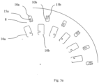
- Figure 5b shows an embodiment whereby a plurality of the steel laminations 8, 9 are rotationally displaced in the circumferential direction relative to the other steel laminations 8, 9.
- two adjacent openings 10a, 10b in each of the steel laminations 8, 9 comprise a different shape, this can be seen more clearly in figure 5a which shows just one of the laminations 8. If one of the laminations 8 is then rotated with respect to an adjacent lamination 9, in this case by 20 degrees, then the two openings 10a, 10b line up to form part of a single cooling channel 7.
- the protrusions 15a and 15b in a pair of adjacent laminations 8,9 extend into the same cooling channel 7 on different sides of the cooling channel 7.
- a serpentine cooling channel is formed.
- the protrusions can be in a radial or circumferential direction as shown in figure 5 .
- the thickness or the number of laminations 8 in each package can be different along the longitudinal direction 6 of the lamination stack 13.
- the cooling performance can therefore be varied along the axial length of the stack for example to improve cooling at the stack side where the preheated cooling medium leaves the cooling channel.
- the number of laminations in a package 11, 12 is less than the number of laminations in an adjacent package 11, 12 forming an upstream part of the cooling channel 7.
Landscapes
- Engineering & Computer Science (AREA)
- Power Engineering (AREA)
- Iron Core Of Rotating Electric Machines (AREA)
Priority Applications (3)
| Application Number | Priority Date | Filing Date | Title |
|---|---|---|---|
| EP21000318.2A EP4178080A1 (fr) | 2021-11-09 | 2021-11-09 | Machine électrique |
| PCT/EP2022/079890 WO2023083613A1 (fr) | 2021-11-09 | 2022-10-26 | Machine électrique |
| CN202280063232.4A CN117999728A (zh) | 2021-11-09 | 2022-10-26 | 电机 |
Applications Claiming Priority (1)
| Application Number | Priority Date | Filing Date | Title |
|---|---|---|---|
| EP21000318.2A EP4178080A1 (fr) | 2021-11-09 | 2021-11-09 | Machine électrique |
Publications (1)
| Publication Number | Publication Date |
|---|---|
| EP4178080A1 true EP4178080A1 (fr) | 2023-05-10 |
Family
ID=78617119
Family Applications (1)
| Application Number | Title | Priority Date | Filing Date |
|---|---|---|---|
| EP21000318.2A Pending EP4178080A1 (fr) | 2021-11-09 | 2021-11-09 | Machine électrique |
Country Status (3)
| Country | Link |
|---|---|
| EP (1) | EP4178080A1 (fr) |
| CN (1) | CN117999728A (fr) |
| WO (1) | WO2023083613A1 (fr) |
Citations (5)
| Publication number | Priority date | Publication date | Assignee | Title |
|---|---|---|---|---|
| US20070013241A1 (en) * | 2005-07-13 | 2007-01-18 | Schiferl Rich F | Lamination stack cooling path |
| JP2008312292A (ja) * | 2007-06-12 | 2008-12-25 | Komatsu Ltd | モータ |
| US20140265667A1 (en) * | 2013-03-15 | 2014-09-18 | Ingersoll-Rand Company | Electrical machine having cooling features |
| US20180367003A1 (en) * | 2014-07-25 | 2018-12-20 | Prippell Technologies, Llc | Wound strip machine |
| US20200373803A1 (en) | 2019-05-23 | 2020-11-26 | Dr. Ing. H.C. F. Porsche Aktiengesellschaft | Stator of an electric machine |
-
2021
- 2021-11-09 EP EP21000318.2A patent/EP4178080A1/fr active Pending
-
2022
- 2022-10-26 CN CN202280063232.4A patent/CN117999728A/zh active Pending
- 2022-10-26 WO PCT/EP2022/079890 patent/WO2023083613A1/fr active Application Filing
Patent Citations (5)
| Publication number | Priority date | Publication date | Assignee | Title |
|---|---|---|---|---|
| US20070013241A1 (en) * | 2005-07-13 | 2007-01-18 | Schiferl Rich F | Lamination stack cooling path |
| JP2008312292A (ja) * | 2007-06-12 | 2008-12-25 | Komatsu Ltd | モータ |
| US20140265667A1 (en) * | 2013-03-15 | 2014-09-18 | Ingersoll-Rand Company | Electrical machine having cooling features |
| US20180367003A1 (en) * | 2014-07-25 | 2018-12-20 | Prippell Technologies, Llc | Wound strip machine |
| US20200373803A1 (en) | 2019-05-23 | 2020-11-26 | Dr. Ing. H.C. F. Porsche Aktiengesellschaft | Stator of an electric machine |
Also Published As
| Publication number | Publication date |
|---|---|
| CN117999728A (zh) | 2024-05-07 |
| WO2023083613A1 (fr) | 2023-05-19 |
Similar Documents
| Publication | Publication Date | Title |
|---|---|---|
| EP1215800B1 (fr) | Conduit de refroidissement dans les encoches d'une machine électrique tournante | |
| EP1850458B1 (fr) | Rotor pour machine dynamo-électrique | |
| EP1557929B1 (fr) | Procédé et appareil permettant la réduction de la température des points chauds des bobines exitatrices empilés | |
| EP2230748B1 (fr) | Bloc-espaceur de bobine de machine dynamoélectrique doté d'un canal de déflexion de flux dans sa surface frontale de bobine | |
| EP2312729A1 (fr) | Stator | |
| KR100443114B1 (ko) | 전기기기용회전자권선 | |
| JP7139969B2 (ja) | 回転電機 | |
| EP1946427B1 (fr) | Blocs d'espacement de rotor à aube | |
| US6392326B1 (en) | Flow-through spaceblocks with deflectors and method for increased electric generator endwinding cooling | |
| EP1346457B1 (fr) | Deflecteur de bloc d'espacement destine a un refroidissement ameliore de bobinage d'extremite d'un generateur electrique | |
| EP3136550B1 (fr) | Ensemble de rotor ayant un trajet de refroidissement amélioré | |
| US9548640B2 (en) | Rotor with cooling manifolds | |
| US6495943B2 (en) | Spaceblock scoops for enhanced rotor cavity heat transfer | |
| EP1843450A2 (fr) | Elément en forme de cale et procédé d'amélioration du refroidissement d'un rotor de générateur | |
| WO2019159522A1 (fr) | Structure de refroidissement pour machine électrique rotative | |
| EP4178080A1 (fr) | Machine électrique | |
| JP7334635B2 (ja) | 回転電機 | |
| US20240195251A1 (en) | Direct slot cooling in electric machines | |
| JP7545287B2 (ja) | 回転電機の固定子 | |
| US20240195253A1 (en) | Stator of an electric axial flux machine, and axial flux machine | |
| WO2024046562A1 (fr) | Stator de machine électrique avec canaux de refroidissement internes |
Legal Events
| Date | Code | Title | Description |
|---|---|---|---|
| STAA | Information on the status of an ep patent application or granted ep patent |
Free format text: STATUS: UNKNOWN |
|
| PUAI | Public reference made under article 153(3) epc to a published international application that has entered the european phase |
Free format text: ORIGINAL CODE: 0009012 |
|
| STAA | Information on the status of an ep patent application or granted ep patent |
Free format text: STATUS: THE APPLICATION HAS BEEN PUBLISHED |
|
| AK | Designated contracting states |
Kind code of ref document: A1 Designated state(s): AL AT BE BG CH CY CZ DE DK EE ES FI FR GB GR HR HU IE IS IT LI LT LU LV MC MK MT NL NO PL PT RO RS SE SI SK SM TR |
|
| STAA | Information on the status of an ep patent application or granted ep patent |
Free format text: STATUS: REQUEST FOR EXAMINATION WAS MADE |
|
| 17P | Request for examination filed |
Effective date: 20231110 |
|
| RBV | Designated contracting states (corrected) |
Designated state(s): AL AT BE BG CH CY CZ DE DK EE ES FI FR GB GR HR HU IE IS IT LI LT LU LV MC MK MT NL NO PL PT RO RS SE SI SK SM TR |