EP4177924A1 - Vacuum interrupter assembly, switchgear including vacuum interrupter assembly, and method of configuring vacuum interrupter assembly - Google Patents
Vacuum interrupter assembly, switchgear including vacuum interrupter assembly, and method of configuring vacuum interrupter assembly Download PDFInfo
- Publication number
- EP4177924A1 EP4177924A1 EP21206496.8A EP21206496A EP4177924A1 EP 4177924 A1 EP4177924 A1 EP 4177924A1 EP 21206496 A EP21206496 A EP 21206496A EP 4177924 A1 EP4177924 A1 EP 4177924A1
- Authority
- EP
- European Patent Office
- Prior art keywords
- coupler
- capacitance
- contact
- vapor shield
- field
- Prior art date
- Legal status (The legal status is an assumption and is not a legal conclusion. Google has not performed a legal analysis and makes no representation as to the accuracy of the status listed.)
- Granted
Links
Images




Classifications
-
- H—ELECTRICITY
- H01—ELECTRIC ELEMENTS
- H01H—ELECTRIC SWITCHES; RELAYS; SELECTORS; EMERGENCY PROTECTIVE DEVICES
- H01H33/00—High-tension or heavy-current switches with arc-extinguishing or arc-preventing means
- H01H33/60—Switches wherein the means for extinguishing or preventing the arc do not include separate means for obtaining or increasing flow of arc-extinguishing fluid
- H01H33/66—Vacuum switches
- H01H33/662—Housings or protective screens
- H01H33/66261—Specific screen details, e.g. mounting, materials, multiple screens or specific electrical field considerations
-
- H—ELECTRICITY
- H01—ELECTRIC ELEMENTS
- H01H—ELECTRIC SWITCHES; RELAYS; SELECTORS; EMERGENCY PROTECTIVE DEVICES
- H01H33/00—High-tension or heavy-current switches with arc-extinguishing or arc-preventing means
- H01H33/60—Switches wherein the means for extinguishing or preventing the arc do not include separate means for obtaining or increasing flow of arc-extinguishing fluid
- H01H33/66—Vacuum switches
- H01H33/664—Contacts; Arc-extinguishing means, e.g. arcing rings
-
- H—ELECTRICITY
- H01—ELECTRIC ELEMENTS
- H01H—ELECTRIC SWITCHES; RELAYS; SELECTORS; EMERGENCY PROTECTIVE DEVICES
- H01H33/00—High-tension or heavy-current switches with arc-extinguishing or arc-preventing means
- H01H33/60—Switches wherein the means for extinguishing or preventing the arc do not include separate means for obtaining or increasing flow of arc-extinguishing fluid
- H01H33/66—Vacuum switches
- H01H33/666—Operating arrangements
-
- H—ELECTRICITY
- H01—ELECTRIC ELEMENTS
- H01H—ELECTRIC SWITCHES; RELAYS; SELECTORS; EMERGENCY PROTECTIVE DEVICES
- H01H33/00—High-tension or heavy-current switches with arc-extinguishing or arc-preventing means
- H01H33/60—Switches wherein the means for extinguishing or preventing the arc do not include separate means for obtaining or increasing flow of arc-extinguishing fluid
- H01H33/66—Vacuum switches
- H01H33/662—Housings or protective screens
- H01H33/66261—Specific screen details, e.g. mounting, materials, multiple screens or specific electrical field considerations
- H01H2033/66269—Details relating to the materials used for screens in vacuum switches
-
- H—ELECTRICITY
- H01—ELECTRIC ELEMENTS
- H01H—ELECTRIC SWITCHES; RELAYS; SELECTORS; EMERGENCY PROTECTIVE DEVICES
- H01H33/00—High-tension or heavy-current switches with arc-extinguishing or arc-preventing means
- H01H33/60—Switches wherein the means for extinguishing or preventing the arc do not include separate means for obtaining or increasing flow of arc-extinguishing fluid
- H01H33/66—Vacuum switches
- H01H33/662—Housings or protective screens
- H01H33/66261—Specific screen details, e.g. mounting, materials, multiple screens or specific electrical field considerations
- H01H2033/66284—Details relating to the electrical field properties of screens in vacuum switches
Definitions
- the disclosure generally relates to vacuum interrupters, and more particularly to a vacuum interrupter assembly comprising a field coupler.
- Vacuum interrupters are used in a wide variety of switchgear, e.g. compact medium and high voltage switchgear, insulated or not by gas.
- a typical VI has a stationary contact (a fixed contact) opposing a moveable contact (a nonstationary contact) in a contacting area. By moving the moveable contact away from the stationary contact, a space in between the contacts in the contacting area increases and interrupts a current flowing through the contacts. When the contacts are opened in this way, an electrical discharge (i.e., arcing) occurs between the contacts, and parts of the contacts are evaporated due to the electrical discharge.
- a vapor shield is provided around the contacting area for shielding the VI enclosure from the metal vapor.
- an undesired distortion of the electric field may occur in such a configuration.
- the electric field distortion stems from e.g. an internal asymmetry of the VI, a coupling between other switchgear components (i.e., switchgear elements) such as busbars with the enclosure etc.
- switchgear components i.e., switchgear elements
- the dielectric performance of the VI as a whole is impaired.
- US 2005/082260 A1 discloses a shield encapsulated VI. Two opposing voltage screens are disposed in the vacuum chamber. A semiconductive coating is applied to an exposed central portion of the vacuum chamber. Again, this prior art needs the additional coating, which may be cumbersome to apply.
- US 10,818,455 B2 discloses a VI having an elastomeric insulating sleeve around the VI, an insulating housing molded around the VI and a pair of grading capacitors each including an inner and an outer electrode.
- the insulation between the electrodes is solid insulation of the housing molded at the time when the housing is molded.
- the capacitance of the field grading capacitors is substantially equal to each other.
- This prior art requires that the electrodes of the field grading capacitors are molded into the insulating housing at the time of manufacturing the VI.
- the field grading capacitors do not account for asymmetrical field distortions.
- Vacuum interrupters are often used in different kinds of switchgear, thus resulting in different electrical environments.
- the different properties may result in that one and the same vacuum interrupter has different dielectric characteristics in different settings, e.g. in different kinds and/or configurations of switchgear.
- the prior-art techniques discussed above require that any elements that account for field distortion are present at the time of manufacturing the VI, or which may be cumbersome to apply after the manufacturing process.
- a vacuum interrupter, VI, assembly comprising a VI and at least one field coupler comprising an electrically conductive material.
- the VI has a moveable contact that is moveable relative to a stationary contact along an axis of the VI.
- the stationary and moveable contacts define a contacting area.
- the stationary contact is on an electrical potential which is referred herein to as stationary-contact potential.
- the moveable contact is on an electrical potential which is referred herein to as moveable-contact potential.
- a vapor shield is disposed around the contacting area.
- the stationary contact and the vapor shield have a predetermined mutual capacitance defined as a stationary contact-vapor shield capacitance.
- the moveable contact and the vapor shield have a predetermined mutual capacitance defined as a moveable contact-vapor shield capacitance.
- the field coupler is arranged and configured such that it adds a field coupler capacitance to at least one of the stationary contact-vapor shield capacitance and the moveable contact-vapor shield capacitance, such that the resultant stationary contact-vapor shield moveable contact-vapor shield capacitances are substantially equal.
- the stationary contact-vapor shield capacitance is the capacitance that is established between the stationary contact and the vapor shield.
- the moveable contact-vapor shield capacitance is the capacitance that is established between the moveable contact and the vapor shield.
- Both the stationary contact-vapor shield capacitance and the moveable contact-vapor shield capacitance need not necessarily be known by their exact value, but within a deviation range, e.g. due to a parasitic error such as a measurement deviation, a simulation deviation with respect to reality, etc.
- the deviation range is, for example, 20% or less of the true value, preferably 10% or less of the true value, of the respective capacitance.
- substantially equal includes a certain deviation from perfect equality; yet the capacitances have values sufficiently close to each other such that detrimental effects on the dielectric behavior of the VI are alleviated.
- substantially equal includes a deviation from perfect equality of about 10% or less; in another example, substantially equal, as used herein, includes a deviation from perfect equality of about 20% or less.
- the field coupler by adding the field coupler capacitance, counterbalances to some extent the field asymmetry of the electric field in the VI, and screens a field distortion effect of e.g. a switchgear tank that the VI is actually installed in. This may help to reduce a shift of a vapor shield potential to an unfavorable value, and decrease the electric field strength on the contacts. For example, the maximum field stress in an actual switchgear in which the VI assembly is installed in is significantly lowered.
- one field coupler is provided, and the field coupler is galvanically connected to either the moveable contact potential or the stationary contact potential.
- the field coupler capacitance is configured such that it is substantially the difference between the stationary contact-vapor shield capacitance and the moveable contact-vapor shield capacitance.
- the field coupler capacitance is configured such that it is substantially the difference between the moveable contact-vapor shield capacitance and the stationary contact-vapor shield capacitance.
- two field couplers are provided, and a first field coupler of the two field couplers is galvanically connected to the moveable contact potential, and a second field coupler of the two field couplers is galvanically connected to the stationary contact potential.
- a field coupler capacitance of the first field coupler and a field coupler capacitance of the second field coupler are configured such that the sum of the moveable contact-vapor shield capacitance and the field coupler capacitance of the first field coupler is substantially the sum of the stationary contact-vapor shield capacitance and the field coupler capacitance of the second field coupler.
- a plurality of field couplers is provided.
- n field couplers are galvanically connected to the moveable contact potential each contributing to and summing up to a moveable-contact field coupler capacitance, where n is an integer equal to or greater than 1, wherein the moveable-contact field coupler capacitance is configured such that it is substantially the difference between the stationary contact-vapor shield capacitance and the moveable contact-vapor shield capacitance.
- n field couplers galvanically connected to the stationary contact potential each contributing to and summing up to a stationary-contact field coupler capacitance, where n is an integer equal to or greater than 1, wherein the stationary-contact field coupler capacitance is configured such that it is substantially the difference between the moveable contact-vapor shield capacitance and the stationary contact-vapor shield capacitance.
- the stationary-contact field coupler capacitance and the moveable-contact field coupler capacitance are configured such that the sum of the moveable-contact field coupler capacitance and the moveable contact-vapor shield capacitance is substantially the sum of the stationary-contact field coupler capacitance and the stationary contact-vapor shield capacitance.
- a floating field coupler is provided.
- the floating field coupler is on a floating potential, i.e. is not galvanically connected to any defined potential of the VI.
- the field coupler in this case can be thought of a series connection of a first and a second partial capacitance, wherein the floating potential is present on a connection point of the series connection.
- the first and second partial capacitances are in series connection between the vapor shield and one of either the stationary contact or the moveable contact.
- An additional coupling capacitance is present between the floating potential and the ground potential.
- the partial capacitances are configured such that the sum of the stationary contact-vapor shield capacitance and a term in which the product of the first partial capacitance and the additional coupling capacitance is divided by the sum of the first partial capacitance and the second partial capacitance and the additional coupling capacitance is substantially equal the sum of the moving contact-vapor shield capacitance and a term in which the product of the first partial capacitance and the second partial capacitance is divided by the sum of the first partial capacitance and the second partial capacitance and the additional coupling capacitance.
- the field coupler capacitance is configured by approximation.
- the approximation employs a concentric cylinder formula of the capacitance.
- each field coupler is galvanically connected to at most one of the stationary contact potential or the moveable contact potential.
- the field coupler or the field couplers is/are either floating or only connected to either the stationary contact potential or the moveable contact potential.
- each of the vapor shield, the stationary contact and the moveable contact have metal surfaces exposed towards the contacting area.
- each of the vapor shield, the stationary contact and the moveable contact are, at least in a region thereof directing towards the contacting area and having a main electrical impact on the contacting area, uncoated.
- the field coupler is substantially entirely made of the electrically conductive material.
- at least a plate-like part in a vicinity of the contacting area, as discussed below, is substantially entirely made of the electrically conductive material.
- An electrically conductive material includes at least one or more of a metal or a metal alloy, such as - without limitation - copper or copper alloy or aluminum or aluminum alloy, or any non-metal material that is treated, e.g. by coating, to be electrically conductive, such as - without limitation - a polymer having a conductive paint coated thereon.
- the field coupler comprises an elongated part and a plate-like part.
- the elongated part extends substantially in the direction of the axis.
- the plate-like part is arranged in a vicinity of the contacting area.
- Vicinity is a region in which the capacitive coupling of the field coupler has an effect on the vapor shield, i.e. the capacitive coupling between one of the feeding directions of the VI and the vapor shield is increased.
- the plate-like part in a projection onto a plane orthogonal to the radial direction, has a substantially round shape.
- the VI has a VI length along a symmetry axis of the VI
- the field coupler has a length in the axial direction that is greater than about 0.2 times the VI length and smaller than about 0.8 times the VI length
- the surface of the field coupler extends about an extension angle between 10 degrees and 180 degrees in the circumferential direction of the VI.
- a switchgear comprising at least one switchgear element and a vacuum interrupter assembly as described herein.
- the at least one switchgear element contributes to at least one of the predetermined stationary contact-vapor shield capacitance and the predetermined moveable contact-vapor shield capacitance.
- the field coupler is configured and arranged such as to account for making the stationary contact-vapor shield capacitance and the moveable contact-vapor shield capacitance substantially equal, with the respective amount that the switchgear element(s) contribute(s) thereto.
- Switchgear element includes e.g. a constituent element, a constituent component, a component part, a section etc. of the switchgear, excluding the VI assembly itself or parts of the VI assembly itself.
- the switchgear element is e.g. a component of the switchgear that is present on the switchgear or in the electrical environment of the switchgear, and that has an electrical influence on the at least one of the stationary contact-vapor shield capacitance and the predetermined moveable contact-vapor shield capacitance such that the respective capacitance is influenced, or changed, when the VI assembly is installed in/on the switchgear.
- a method of configuring a vacuum interrupter assembly comprises a vacuum interrupter, VI, having a stationary contact on a stationary contact potential, a moveable contact on a moveable contact potential.
- the stationary contact and the moveable contact define a contacting area.
- the VI further comprises a vapor shield disposed around the contacting area.
- the moveable contact is moveable relative to the stationary contact along an axis of the VI.
- the stationary contact and the vapor shield have a predetermined stationary contact-vapor shield capacitance with respect to each other.
- the moveable contact and the vapor shield have a predetermined moveable contact-vapor shield capacitance with respect to each other.
- the method comprises determining, particularly by simulation, a configuration and arrangement of a field coupler comprising an electrically conductive material such that the field coupler adds a field coupler capacitance to at least one of the stationary contact-vapor shield capacitance and the moveable contact-vapor shield capacitance to make the stationary contact-vapor shield capacitance and the moveable contact-vapor shield capacitance substantially equal.
- Figs. 1a through 1c illustrate a perspective view, a plan view from one angle, and a plan view from another angle, respectively, of an exemplary field coupler 10 used in certain embodiments.
- the field coupler 10 in this illustration is substantially entirely made of a conductive material and comprises an elongated part 11 and a plate-like, substantially round part 12.
- the elongated part 11 mainly serves for mounting the field coupler 10 in place and for positioning the plate-like part 12 such that it has a favorable capacitive coupling with constituent elements of a vacuum interrupter, to be described below.
- Figs. 2 through 9 each show a vacuum interrupter assembly 100 comprising a vacuum interrupter 200 and the field coupler 10.
- the term "vacuum interrupter” may be abbreviated herein as "VI”, as appropriate.
- the VI 200 includes a housing, or encapsulation, 260 disposed around the contacting area 230.
- a stationary, or fixed, contact 210 arranged opposite to a nonstationary, or moveable, contact 220 inside the housing 260.
- the moveable contact 220 is moveable along an axis A.
- the moveable contact 220 is shown as the bottom contact
- the stationary contact 210 is shown as the top contact.
- a contacting area 230 is formed in a region around the bottom end of the stationary contact 210 and the top end of the moveable contact 220.
- the arc is formed in the contacting area 230 between the contacts 210, 220.
- the arc may result in an evaporation of some of the metal material forming the contacts 210, 220.
- a vapor shield 250 is disposed around the contacting area for alleviating an impact of the evaporated metal material onto an inner surface of the housing 260.
- the vapor shield 250 is on a floating electrical potential.
- the vapor shield 250 is not galvanically connected with any one of the stationary or moveable contacts 210, 220, or ground.
- the VI 200 is installed in a compact medium or high voltage switchgear.
- Medium or high voltage typically includes a rating in a range of about 10 kV to about 200 kV.
- the configuration and arrangement of elements of the switchgear such as a busbar, neighboring VIs for other phases etc., and/or the configuration and arrangement of elements of the VI 200 itself, such as the enclosure 260 and an internally asymmetric configuration of the VI 200 etc., may lead to a distortion of an electric field that is present in and around the contacting area 230 both during a period when the VI 200 is conducting (i.e., closed) and when the VI 200 is opened.
- Such one or more elements of the switchgear i.e., a switchgear element or multiple switchgear elements
- the one or more switchgear elements contribute to the respective capacitances of the VI 200.
- the one or more switchgear elements having such an influence include e.g. a constituent element, a constituent component, a component part, a section etc. of the switchgear, excluding the VI 200 itself or parts of the VI 200 itself. Such a distortion of the electric field might compromise the dielectric performance of the VI 200.
- the dielectric performance of the VI 200 may depend on the actual switchgear that the VI 200 is installed in.
- the VI 200 is put into close proximity to other live parts of the switchgear, and grounded components such as a grounded tank.
- the electric field at the VI 200 contacts 210, 220 is enhanced, and thus, the VI dielectric performance is degraded.
- the dielectric performance of the VI 200 depends to a great extent on the capacitances of VI 200, probably influenced by the element(s) of the switchgear. It was found that among the capacitances, there are two capacitances that are favorably made substantially equal, namely a capacitance C F-S between the stationary contact (210) and the vapor shield (250), and a capacitance C M-S between the moveable contact (220) and the vapor shield.
- the capacitance C F-S is herein also referred to as the stationary contact-vapor shield capacitance.
- the capacitance C M-S is herein also referred to as the moveable contact-vapor shield capacitance.
- the capacitances C F-S , C M-S are parasitic capacitances that influence, e.g. distort, the electric field in the contacting area 230, and that the capacitances C F-S , C M-S are predetermined for a given electrical environment of the VI 200, e.g. in a given switchgear environment.
- the capacitances C F-S , C M-S may be obtained for the given electrical environment of the VI 200, for example, by known methods, among others by known methods of calculation, measuring, simulation, or any combination thereof.
- the VI assemblies 100 contribute to alleviating the distortion of the electric field, thus helping to achieve a favorable dielectric performance or behavior of the VI 200 in the actual switchgear that it is installed in.
- one or more field couplers 10 are installed.
- the field coupler(s) 10 is/are arranged such that at least a part thereof is at an outer circumferential surface of the housing 260 in a field coupling region F such that it capacitively couples with the vapor shield 250.
- the field coupler 10 adds a field coupler capacitance C coupler to at least one of the stationary contact-vapor shield capacitance C F-S and the moveable contact-vapor shield capacitance C M-S .
- the field coupler 10 is configured and arranged such that it makes the stationary contact-vapor shield capacitance C F-S and the moveable contact-vapor shield capacitance C M-S substantially equal. For example, a deviation of at most 10% or at most 5% between the stationary contact-vapor shield capacitance C F-S and the moveable contact-vapor shield capacitance C M-S is achieved by adding the field coupler capacitance C coupler via the field coupler 10.
- the field coupler capacitance C coupler may be obtained by a known method, such as methods of calculation, measuring, simulation, or any combination thereof. For example, when the field coupler capacitance C coupler is obtained, a shape, a material, a mounting position, a mounting orientation, or a combination thereof may be established by multiple iterations of electrical field simulation. Conditions for any such simulation may include to optimize the field coupler capacitance C coupler that the shape provides, minimize the breakdown probability between neighboring field couplers 10, or a combination thereof.
- the field coupler capacitance C coupler is obtained for a state in which the contacts 210, 220 of the VI 200 are in an open position.
- the field coupler capacitance C coupler may also be obtained for a state in which the contacts 210, 220 of the VI 200 are in an intermediate position.
- the field coupler 10 thus interacts capacitively, through the housing 260, with the vapor shield 250.
- the field coupler 10 may help to correct a field asymmetry resulting from e.g. an internal VI 200 geometry and/or imposed by other switchgear elements, as discussed above.
- the field coupler 10 may further help to reduce the capacitive coupling between the VI 200 and switchgear elements, particularly a switchgear tank. Provision of the field coupler 10 may also have the effect to reduce the capacitive coupling of the VI 200 components to the ground potential.
- one field coupler 10 is mounted on the moveable contact 220 such that at least the plate-like part 12 thereof extends on the outside of the housing 260.
- the field coupler 10 is galvanically brought to the potential of the moveable contact 220.
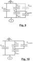
- the equivalent circuit shown in Fig. 9 relates to this configuration.
- any connections shown in the circuit diagrams are not necessarily of galvanic nature, and may also be e.g. of capacitive nature.
- the field coupler capacitance C coupler imposed by the field coupler 10 of Fig. 2 is, at one end thereof, galvanically connected to one end of the moveable contact-vapor shield capacitance C M-S .
- one field coupler 10 is mounted on the stationary contact 210 such that at least the plate-like part 12 thereof extends on the outside of the housing 260.
- the field coupler 10 is galvanically brought to the potential of the stationary contact 210.
- the equivalent circuit shown in Fig. 10 relates to this configuration.
- the field coupler capacitance C coupler imposed by the field coupler 10 of Fig. 3 is, at one end thereof, galvanically connected to one end of the stationary contact-vapor shield capacitance Cc-s. It is capacitively coupled to the shield potential Vs between the stationary contact-vapor shield capacitance C F-S and the moveable contact-vapor shield capacitance C M-S .
- one field coupler 10-m is mounted on the moveable contact 220 such that at least the plate-like part 12 thereof extends on the outside of the housing 260
- one field coupler 10-f is mounted on the stationary contact 210 such that at least the plate-like part 12 thereof extends on the outside of the housing 260.
- the field coupler 10-f is galvanically brought to the potential of the stationary contact 210.
- the field coupler 10-m is galvanically brought to the potential of the moveable contact 220.
- the equivalent circuit shown in Fig. 11 relates to this configuration.
- the field coupler capacitance C coupler, f imposed by the field coupler 10-f of Fig. 4 is, at one end thereof, galvanically connected to one end of the stationary contact-vapor shield capacitance Cc-s. It is capacitively coupled to the shield potential Vs between the stationary contact-vapor shield capacitance C F-S and the moveable contact-vapor shield capacitance C M-S .
- two field couplers 10-m,1 10-m,2 are mounted on the moveable contact 220 such that at least the plate-like part 12 thereof extends on the outside of the housing 260.
- the field couplers 10-m,1 10-m,2 are galvanically brought to the potential of the moveable contact 220.
- the plate-like parts 12 are each mounted closer to the contacting area 230, while in Fig. 6 , the plate-like parts 12 are each mounted further away from the contacting area 230.
- the respective field coupler capacitances C coupler,1, C coupler ,2 imposed by the field couplers 10-f,1, 10-f,2 are, at one end thereof, galvanically connected to one end of the stationary contact-vapor shield capacitance C F-S .
- field couplers 10-m,1 10-m,2, 10-m,3, 10-m,4 are mounted on the moveable contact 220 such that at least the plate-like part 12 thereof extends on the outside of the housing 260.
- the field couplers 10-m,1 10-m,2, 10-m,3, 10-m,4 are galvanically brought to the potential of the moveable contact 220.
- two field couplers 10-m,1 10-m,2 are mounted on the moveable contact 220 such that at least the plate-like part 12 thereof extends on the outside of the housing 260
- two field couplers 10-f,1 10-f,2 are mounted on the stationary contact 210 such that at least the plate-like part 12 thereof extends on the outside of the housing 26.
- the two field couplers 10-f,1 10-f,2 are galvanically brought to the potential of the stationary contact 210.
- the two field couplers 10-m,1 10-m,2 are galvanically brought to the potential of the moveable contact 220.
- the field couplers 10-m,1 10-m,2 have a field coupler capacitance C coupler,m1 , C coupler,m2 , respectively.
- the field couplers 10-f,1 10-f,2 have a field coupler capacitance C coupler,f1 , C coupler,f2 , respectively.
- one floating field coupler is provided.
- the floating field coupler is on floating potential, i.e. it is neither connected to the potential of the stationary contact 210, nor to that of the moveable contact 220.
- the floating field coupler can be divided into two partial floating field couplers, of which one provides a field coupler capacitance C coupler,1v , and the other one provides a field coupler capacitance C coupler,2v .
- the floating field coupler is arranged such that it capacitively couples to the moveable electrode 220.
- the field coupler capacitances C coupler,1v , C coupler,2v are each connected to different ends of the moveable contact-vapor shield capacitance C M-S .
- the field coupler capacitance C coupler,1v is connected to shield potential Vs.
- the field coupler capacitances C coupler,1v , C coupler,2v are on floating voltage Vc.
- an additional coupling capacitance CC-G is present between the floating potential Vs and ground potential.
- the floating field coupler has a capacitive coupling to ground since it is on floating potential.
- a vapor shield-ground capacitance CS-G i.e. the capacitance that is established between the vapor shield 250 and a ground potential.
- the vapor shield-ground capacitance C S-G consideration may be made as to the vapor shield-ground capacitance C S-G.
- the field coupler capacitance C coupler may be configured such that the vapor shield-ground capacitance CS-G is less than a sum of the moveable contact-vapor shield capacitance C M-S and the field coupler capacitance C coupler .
- Fig. 14 illustrates a schematic drawing used for explanatory purposes, for performing an approximative calculation of a capacitance.
- the exemplary approximation is a rough one, and finer approximations may be conducted either by way of simulation and/or calculation, as need be.
- the field coupler capacitance is determined by way of approximation.
- R 1 is the radial distance from the axis to an outer circumferential surface of the vapor shield
- R 2 is the radial distance from the axis to a surface of the field coupler opposing the outer circumferential surface of the vapor shield
- ⁇ is the angle - in radian - of extension of the surface of the field coupler in a circumferential direction
- 1 is the length of the field coupler in the axial direction
- ⁇ is the permittivity in the space between the field coupler and the vapor shield.
- a dielectric simulation was performed for an exemplary standalone VI 200 and the same type of VI 200 installed in a switchgear. While in the standalone VI 200 the maximum stress on the contacts was still on a permissible level for the application of a certain electrical field strength E 1 , with a vapor shield potential having a certain value V S1 in a range between 50 kV and 100 kV, upon installation of the VI 200 in the switchgear, the vapor shield potential shifted to approximately 0.94 times Vsi due to internal field distortion and capacitive coupling to a tank of the switchgear. Thereby, the stress acting on the contacts increased to approximately 1.03 times E 1 , which was outside the permissible range.
- the vapor shield potential was brought back to approximately Vsi, and the stress on the contacts was lowered to approximately 0.99 times E 1 . Thereby, the risk of a dielectric breakdown can be significantly lowered.
Landscapes
- Fixed Capacitors And Capacitor Manufacturing Machines (AREA)
- Shielding Devices Or Components To Electric Or Magnetic Fields (AREA)
- High-Tension Arc-Extinguishing Switches Without Spraying Means (AREA)
Abstract
Description
- The disclosure generally relates to vacuum interrupters, and more particularly to a vacuum interrupter assembly comprising a field coupler.
- Vacuum interrupters (VIs) are used in a wide variety of switchgear, e.g. compact medium and high voltage switchgear, insulated or not by gas. A typical VI has a stationary contact (a fixed contact) opposing a moveable contact (a nonstationary contact) in a contacting area. By moving the moveable contact away from the stationary contact, a space in between the contacts in the contacting area increases and interrupts a current flowing through the contacts. When the contacts are opened in this way, an electrical discharge (i.e., arcing) occurs between the contacts, and parts of the contacts are evaporated due to the electrical discharge. A vapor shield is provided around the contacting area for shielding the VI enclosure from the metal vapor.
- Particularly in a case in which miniaturization of the components is demanded, an undesired distortion of the electric field may occur in such a configuration. The electric field distortion stems from e.g. an internal asymmetry of the VI, a coupling between other switchgear components (i.e., switchgear elements) such as busbars with the enclosure etc. When the electric field is distorted, the dielectric performance of the VI as a whole is impaired.
-
US 4,002,867 A discloses a VI having a condensing shield with a coating, the coating directly steering the potential of the vapor shield. This prior art needs the additional coating, which may be cumbersome to apply.. -
US 2005/082260 A1 discloses a shield encapsulated VI. Two opposing voltage screens are disposed in the vacuum chamber. A semiconductive coating is applied to an exposed central portion of the vacuum chamber. Again, this prior art needs the additional coating, which may be cumbersome to apply. -
US 10,818,455 B2 - Vacuum interrupters are often used in different kinds of switchgear, thus resulting in different electrical environments. The different properties may result in that one and the same vacuum interrupter has different dielectric characteristics in different settings, e.g. in different kinds and/or configurations of switchgear. The prior-art techniques discussed above require that any elements that account for field distortion are present at the time of manufacturing the VI, or which may be cumbersome to apply after the manufacturing process. There is a demand for a vacuum interrupter assembly or a method of configuring a vacuum interrupter assembly in which the vacuum interrupter has favorable dielectric properties that are adaptable to the electrical environment.
- According to an aspect of the present disclosure, a vacuum interrupter, VI, assembly is provided. The VI assembly comprises a VI and at least one field coupler comprising an electrically conductive material. The VI has a moveable contact that is moveable relative to a stationary contact along an axis of the VI. The stationary and moveable contacts define a contacting area. The stationary contact is on an electrical potential which is referred herein to as stationary-contact potential. The moveable contact is on an electrical potential which is referred herein to as moveable-contact potential. A vapor shield is disposed around the contacting area. The stationary contact and the vapor shield have a predetermined mutual capacitance defined as a stationary contact-vapor shield capacitance. The moveable contact and the vapor shield have a predetermined mutual capacitance defined as a moveable contact-vapor shield capacitance. The field coupler is arranged and configured such that it adds a field coupler capacitance to at least one of the stationary contact-vapor shield capacitance and the moveable contact-vapor shield capacitance, such that the resultant stationary contact-vapor shield moveable contact-vapor shield capacitances are substantially equal.
- The stationary contact-vapor shield capacitance is the capacitance that is established between the stationary contact and the vapor shield. The moveable contact-vapor shield capacitance is the capacitance that is established between the moveable contact and the vapor shield. Both the stationary contact-vapor shield capacitance and the moveable contact-vapor shield capacitance need not necessarily be known by their exact value, but within a deviation range, e.g. due to a parasitic error such as a measurement deviation, a simulation deviation with respect to reality, etc. The deviation range is, for example, 20% or less of the true value, preferably 10% or less of the true value, of the respective capacitance.
- Substantially equal, as used herein, includes a certain deviation from perfect equality; yet the capacitances have values sufficiently close to each other such that detrimental effects on the dielectric behavior of the VI are alleviated. In an example, substantially equal, as used herein, includes a deviation from perfect equality of about 10% or less; in another example, substantially equal, as used herein, includes a deviation from perfect equality of about 20% or less.
- An effect provided by the techniques disclosed herein is that the field coupler, by adding the field coupler capacitance, counterbalances to some extent the field asymmetry of the electric field in the VI, and screens a field distortion effect of e.g. a switchgear tank that the VI is actually installed in. This may help to reduce a shift of a vapor shield potential to an unfavorable value, and decrease the electric field strength on the contacts. For example, the maximum field stress in an actual switchgear in which the VI assembly is installed in is significantly lowered.
- In an embodiment, one field coupler is provided, and the field coupler is galvanically connected to either the moveable contact potential or the stationary contact potential. In the variant in which the field coupler is galvanically connected to the moveable contact potential, the field coupler capacitance is configured such that it is substantially the difference between the stationary contact-vapor shield capacitance and the moveable contact-vapor shield capacitance. In the variant in which the field coupler is galvanically connected to the stationary contact potential, the field coupler capacitance is configured such that it is substantially the difference between the moveable contact-vapor shield capacitance and the stationary contact-vapor shield capacitance.
- In an embodiment, two field couplers are provided, and a first field coupler of the two field couplers is galvanically connected to the moveable contact potential, and a second field coupler of the two field couplers is galvanically connected to the stationary contact potential. A field coupler capacitance of the first field coupler and a field coupler capacitance of the second field coupler are configured such that the sum of the moveable contact-vapor shield capacitance and the field coupler capacitance of the first field coupler is substantially the sum of the stationary contact-vapor shield capacitance and the field coupler capacitance of the second field coupler.
- In an embodiment, a plurality of field couplers is provided. In a first variant of the embodiment, n field couplers are galvanically connected to the moveable contact potential each contributing to and summing up to a moveable-contact field coupler capacitance, where n is an integer equal to or greater than 1, wherein the moveable-contact field coupler capacitance is configured such that it is substantially the difference between the stationary contact-vapor shield capacitance and the moveable contact-vapor shield capacitance. In a second variant of the embodiment, n field couplers galvanically connected to the stationary contact potential each contributing to and summing up to a stationary-contact field coupler capacitance, where n is an integer equal to or greater than 1, wherein the stationary-contact field coupler capacitance is configured such that it is substantially the difference between the moveable contact-vapor shield capacitance and the stationary contact-vapor shield capacitance. In a third variant of the embodiment combining the first and second variants, the stationary-contact field coupler capacitance and the moveable-contact field coupler capacitance are configured such that the sum of the moveable-contact field coupler capacitance and the moveable contact-vapor shield capacitance is substantially the sum of the stationary-contact field coupler capacitance and the stationary contact-vapor shield capacitance.
- In an embodiment, a floating field coupler is provided. The floating field coupler is on a floating potential, i.e. is not galvanically connected to any defined potential of the VI. The field coupler in this case can be thought of a series connection of a first and a second partial capacitance, wherein the floating potential is present on a connection point of the series connection. The first and second partial capacitances are in series connection between the vapor shield and one of either the stationary contact or the moveable contact. An additional coupling capacitance is present between the floating potential and the ground potential. The partial capacitances are configured such that the sum of the stationary contact-vapor shield capacitance and a term in which the product of the first partial capacitance and the additional coupling capacitance is divided by the sum of the first partial capacitance and the second partial capacitance and the additional coupling capacitance is substantially equal the sum of the moving contact-vapor shield capacitance and a term in which the product of the first partial capacitance and the second partial capacitance is divided by the sum of the first partial capacitance and the second partial capacitance and the additional coupling capacitance. In another way of expressing this configuration, the first partial capacitance Ccoupler,1v and the second partial capacitance Ccoupler,2v are configured such that the following equation is fulfilled, wherein CC-G designates the additional coupling capacitance, CF-S designates the stationary contact-vapor shield capacitance, CM-S designates the moving contact-vapor shield capacitance, and wherein "=" designates "substantially equal":

- In embodiments, the field coupler capacitance is configured by approximation. The approximation employs a concentric cylinder formula of the capacitance. For example, the equation

- In embodiments, each field coupler is galvanically connected to at most one of the stationary contact potential or the moveable contact potential. In other words: The field coupler or the field couplers is/are either floating or only connected to either the stationary contact potential or the moveable contact potential.
- In embodiments, each of the vapor shield, the stationary contact and the moveable contact have metal surfaces exposed towards the contacting area. In particular, each of the vapor shield, the stationary contact and the moveable contact are, at least in a region thereof directing towards the contacting area and having a main electrical impact on the contacting area, uncoated.
- In embodiments, the field coupler is substantially entirely made of the electrically conductive material. In particular, at least a plate-like part in a vicinity of the contacting area, as discussed below, is substantially entirely made of the electrically conductive material. An electrically conductive material, as used herein, includes at least one or more of a metal or a metal alloy, such as - without limitation - copper or copper alloy or aluminum or aluminum alloy, or any non-metal material that is treated, e.g. by coating, to be electrically conductive, such as - without limitation - a polymer having a conductive paint coated thereon.
- In embodiments, the field coupler comprises an elongated part and a plate-like part. The elongated part extends substantially in the direction of the axis. The plate-like part is arranged in a vicinity of the contacting area. Vicinity, as used herein, is a region in which the capacitive coupling of the field coupler has an effect on the vapor shield, i.e. the capacitive coupling between one of the feeding directions of the VI and the vapor shield is increased. In embodiments, in a projection onto a plane orthogonal to the radial direction, the plate-like part has a substantially round shape.
- In embodiments, the VI has a VI length along a symmetry axis of the VI, and the field coupler has a length in the axial direction that is greater than about 0.2 times the VI length and smaller than about 0.8 times the VI length, and the surface of the field coupler extends about an extension angle between 10 degrees and 180 degrees in the circumferential direction of the VI.
- According to another aspect of the present disclosure, a switchgear is provided. The switchgear comprises at least one switchgear element and a vacuum interrupter assembly as described herein. The at least one switchgear element contributes to at least one of the predetermined stationary contact-vapor shield capacitance and the predetermined moveable contact-vapor shield capacitance. Thus, the field coupler is configured and arranged such as to account for making the stationary contact-vapor shield capacitance and the moveable contact-vapor shield capacitance substantially equal, with the respective amount that the switchgear element(s) contribute(s) thereto.
- Switchgear element, as used herein, includes e.g. a constituent element, a constituent component, a component part, a section etc. of the switchgear, excluding the VI assembly itself or parts of the VI assembly itself. In other words: The switchgear element is e.g. a component of the switchgear that is present on the switchgear or in the electrical environment of the switchgear, and that has an electrical influence on the at least one of the stationary contact-vapor shield capacitance and the predetermined moveable contact-vapor shield capacitance such that the respective capacitance is influenced, or changed, when the VI assembly is installed in/on the switchgear.
- According to yet another aspect of the present disclosure, a method of configuring a vacuum interrupter assembly is provided. The vacuum interrupter assembly comprises a vacuum interrupter, VI, having a stationary contact on a stationary contact potential, a moveable contact on a moveable contact potential. The stationary contact and the moveable contact define a contacting area. The VI further comprises a vapor shield disposed around the contacting area.
- The moveable contact is moveable relative to the stationary contact along an axis of the VI. The stationary contact and the vapor shield have a predetermined stationary contact-vapor shield capacitance with respect to each other. The moveable contact and the vapor shield have a predetermined moveable contact-vapor shield capacitance with respect to each other. The method comprises determining, particularly by simulation, a configuration and arrangement of a field coupler comprising an electrically conductive material such that the field coupler adds a field coupler capacitance to at least one of the stationary contact-vapor shield capacitance and the moveable contact-vapor shield capacitance to make the stationary contact-vapor shield capacitance and the moveable contact-vapor shield capacitance substantially equal.
- The techniques disclosed herein will be even more apparent in the following description of embodiments by referring to the accompanying drawings in which:
-
Fig. 1a illustrates a perspective view of an exemplary field coupler used in certain embodiments; -
Fig. 1b illustrates the exemplary field coupler ofFig. 1a in a plan view; -
Fig. 1c illustrates the exemplary field coupler ofFigs. 1a and 1b in a plan view from a different angle; -
Fig. 2 illustrates an example of a VI assembly according to an embodiment; -
Fig. 3 illustrates an example of a VI assembly according to another embodiment; -
Fig. 4 illustrates an example of a VI assembly according to another embodiment; -
Fig. 5 illustrates an example of a VI assembly according to yet another embodiment; -
Fig. 6 illustrates an example of a VI assembly according to yet another embodiment; -
Fig. 7 illustrates an example of a VI assembly according to yet another embodiment; -
Fig. 8 illustrates an example of a VI assembly according to yet another embodiment; -
Fig. 9 illustrates a simplified equivalent circuit diagram of the capacitances in an embodiment; -
Fig. 10 illustrates a simplified equivalent circuit diagram of the capacitances in another embodiment; -
Fig. 11 illustrates a simplified equivalent circuit diagram of the capacitances in yet another embodiment; -
Fig. 12 illustrates a simplified equivalent circuit diagram of the capacitances in yet another embodiment; -
Fig. 13 illustrates a simplified equivalent circuit diagram of the capacitances in yet another embodiment; -
Fig. 14 illustrates a schematic drawing used for explanatory purposes, for performing an approximative calculation of a capacitance. -
Figs. 1a through 1c illustrate a perspective view, a plan view from one angle, and a plan view from another angle, respectively, of anexemplary field coupler 10 used in certain embodiments. Thefield coupler 10 in this illustration is substantially entirely made of a conductive material and comprises anelongated part 11 and a plate-like, substantiallyround part 12. Theelongated part 11 mainly serves for mounting thefield coupler 10 in place and for positioning the plate-like part 12 such that it has a favorable capacitive coupling with constituent elements of a vacuum interrupter, to be described below. -
Figs. 2 through 9 each show avacuum interrupter assembly 100 comprising avacuum interrupter 200 and thefield coupler 10. The term "vacuum interrupter" may be abbreviated herein as "VI", as appropriate. TheVI 200 includes a housing, or encapsulation, 260 disposed around the contactingarea 230. A stationary, or fixed, contact 210 arranged opposite to a nonstationary, or moveable, contact 220 inside thehousing 260. Themoveable contact 220 is moveable along an axis A. In the drawings, themoveable contact 220 is shown as the bottom contact, and thestationary contact 210 is shown as the top contact. In a region around the bottom end of thestationary contact 210 and the top end of themoveable contact 220, a contactingarea 230 is formed. - In the state shown in
Figs. 2 through 9 , an opening operation of theVI 200 has just been initiated. Thestationary contact 210 and themoveable contact 220 are still close to each other but a small gap is formed therebetween in the contactingarea 230. When theVI 200 is conducting a current flows through the stationary andmoveable contacts contacts contacts contacts area 230 between thecontacts contacts vapor shield 250 is disposed around the contacting area for alleviating an impact of the evaporated metal material onto an inner surface of thehousing 260. - The
vapor shield 250 is on a floating electrical potential. In particular, in the type ofVI 200 described herein, thevapor shield 250 is not galvanically connected with any one of the stationary ormoveable contacts - Typically, the
VI 200 is installed in a compact medium or high voltage switchgear.. Medium or high voltage, as used herein, typically includes a rating in a range of about 10 kV to about 200 kV. In a conventional setting, the configuration and arrangement of elements of the switchgear, such as a busbar, neighboring VIs for other phases etc., and/or the configuration and arrangement of elements of theVI 200 itself, such as theenclosure 260 and an internally asymmetric configuration of theVI 200 etc., may lead to a distortion of an electric field that is present in and around the contactingarea 230 both during a period when theVI 200 is conducting (i.e., closed) and when theVI 200 is opened. Such one or more elements of the switchgear (i.e., a switchgear element or multiple switchgear elements), thus have an influence on the various capacitances of theVI 200, including the capacitances of thecontacts vapor shield 250, as discussed further below. In other words: The one or more switchgear elements contribute to the respective capacitances of theVI 200. The one or more switchgear elements having such an influence include e.g. a constituent element, a constituent component, a component part, a section etc. of the switchgear, excluding theVI 200 itself or parts of theVI 200 itself. Such a distortion of the electric field might compromise the dielectric performance of theVI 200. As mentioned above, the dielectric performance of theVI 200 may depend on the actual switchgear that theVI 200 is installed in. For example, theVI 200 is put into close proximity to other live parts of the switchgear, and grounded components such as a grounded tank. As a result, the electric field at theVI 200contacts - The dielectric performance of the
VI 200 depends to a great extent on the capacitances ofVI 200, probably influenced by the element(s) of the switchgear. It was found that among the capacitances, there are two capacitances that are favorably made substantially equal, namely a capacitance CF-S between the stationary contact (210) and the vapor shield (250), and a capacitance CM-S between the moveable contact (220) and the vapor shield. The capacitance CF-S is herein also referred to as the stationary contact-vapor shield capacitance. The capacitance CM-S is herein also referred to as the moveable contact-vapor shield capacitance. Note that the capacitances CF-S, CM-S are parasitic capacitances that influence, e.g. distort, the electric field in the contactingarea 230, and that the capacitances CF-S, CM-S are predetermined for a given electrical environment of theVI 200, e.g. in a given switchgear environment. The capacitances CF-S, CM-S may be obtained for the given electrical environment of theVI 200, for example, by known methods, among others by known methods of calculation, measuring, simulation, or any combination thereof. - The
VI assemblies 100 according to embodiments as described herein contribute to alleviating the distortion of the electric field, thus helping to achieve a favorable dielectric performance or behavior of theVI 200 in the actual switchgear that it is installed in. To that end, one ormore field couplers 10 are installed. The field coupler(s) 10 is/are arranged such that at least a part thereof is at an outer circumferential surface of thehousing 260 in a field coupling region F such that it capacitively couples with thevapor shield 250. Thefield coupler 10 adds a field coupler capacitance Ccoupler to at least one of the stationary contact-vapor shield capacitance CF-S and the moveable contact-vapor shield capacitance CM-S. Thefield coupler 10 is configured and arranged such that it makes the stationary contact-vapor shield capacitance CF-S and the moveable contact-vapor shield capacitance CM-S substantially equal. For example, a deviation of at most 10% or at most 5% between the stationary contact-vapor shield capacitance CF-S and the moveable contact-vapor shield capacitance CM-S is achieved by adding the field coupler capacitance Ccoupler via thefield coupler 10. - The field coupler capacitance Ccoupler may be obtained by a known method, such as methods of calculation, measuring, simulation, or any combination thereof. For example, when the field coupler capacitance Ccoupler is obtained, a shape, a material, a mounting position, a mounting orientation, or a combination thereof may be established by multiple iterations of electrical field simulation. Conditions for any such simulation may include to optimize the field coupler capacitance Ccoupler that the shape provides, minimize the breakdown probability between neighboring
field couplers 10, or a combination thereof. - For example, the field coupler capacitance Ccoupler is obtained for a state in which the
contacts VI 200 are in an open position. However, the field coupler capacitance Ccoupler may also be obtained for a state in which thecontacts VI 200 are in an intermediate position. - The
field coupler 10 thus interacts capacitively, through thehousing 260, with thevapor shield 250. Thefield coupler 10 may help to correct a field asymmetry resulting from e.g. aninternal VI 200 geometry and/or imposed by other switchgear elements, as discussed above. Thefield coupler 10 may further help to reduce the capacitive coupling between theVI 200 and switchgear elements, particularly a switchgear tank. Provision of thefield coupler 10 may also have the effect to reduce the capacitive coupling of theVI 200 components to the ground potential. - In the following, specific embodiments depicted in
Figs. 2 through 8 are discussed. Equivalent circuits depicted inFigs. 9 through 13 partially corresponding to the configurations inFigs. 2 through 8 are also referred to. In the equivalent circuits shown inFigs. 9 through 13 , the capacitance CF-M between thecontacts contacts field coupler 10 screens thecontacts vapor shield 250 from the ground, which reduces the negative impact of a capacitive coupling to the ground. - In the embodiment shown in
Fig. 2 , onefield coupler 10 is mounted on themoveable contact 220 such that at least the plate-like part 12 thereof extends on the outside of thehousing 260. Thefield coupler 10 is galvanically brought to the potential of themoveable contact 220. The equivalent circuit shown inFig. 9 relates to this configuration. In any equivalent circuit shown herein, any connections shown in the circuit diagrams are not necessarily of galvanic nature, and may also be e.g. of capacitive nature. InFig. 9 , the field coupler capacitance Ccoupler imposed by thefield coupler 10 ofFig. 2 is, at one end thereof, galvanically connected to one end of the moveable contact-vapor shield capacitance CM-S. It is capacitively coupled to the shield potential Vs between the stationary contact-vapor shield capacitance CF-S and the moveable contact-vapor shield capacitance CM-S. Thefield coupler 10 is designed, configured and arranged such that it adds the field coupler capacitance Ccoupler to the moveable contact-vapor shield capacitance CM-S such that CF-S=CM-S+Ccoupler. - In the embodiment shown in
Fig. 3 , onefield coupler 10 is mounted on thestationary contact 210 such that at least the plate-like part 12 thereof extends on the outside of thehousing 260. Thefield coupler 10 is galvanically brought to the potential of thestationary contact 210. The equivalent circuit shown inFig. 10 relates to this configuration. InFig. 10 , the field coupler capacitance Ccoupler imposed by thefield coupler 10 ofFig. 3 is, at one end thereof, galvanically connected to one end of the stationary contact-vapor shield capacitance Cc-s. It is capacitively coupled to the shield potential Vs between the stationary contact-vapor shield capacitance CF-S and the moveable contact-vapor shield capacitance CM-S. Thefield coupler 10 is designed, configured and arranged such that it adds the field coupler capacitance Ccoupler to the stationary contact-vapor shield capacitance CF-S such that CM-S=CF-S+Ccoupler. - In the embodiment shown in
Fig. 4 , one field coupler 10-m is mounted on themoveable contact 220 such that at least the plate-like part 12 thereof extends on the outside of thehousing 260, and one field coupler 10-f is mounted on thestationary contact 210 such that at least the plate-like part 12 thereof extends on the outside of thehousing 260. The field coupler 10-f is galvanically brought to the potential of thestationary contact 210. The field coupler 10-m is galvanically brought to the potential of themoveable contact 220. The equivalent circuit shown inFig. 11 relates to this configuration. InFig. 11 , the field coupler capacitance Ccoupler, m imposed by the field coupler 10-m ofFig. 4 is, at one end thereof, galvanically connected to one end of the moveable contact-vapor shield capacitance CM-S. It is capacitively coupled to the shield potential Vs between the stationary contact-vapor shield capacitance CF-S and the moveable contact-vapor shield capacitance CM-S. The field coupler capacitance Ccoupler, f imposed by the field coupler 10-f ofFig. 4 is, at one end thereof, galvanically connected to one end of the stationary contact-vapor shield capacitance Cc-s. It is capacitively coupled to the shield potential Vs between the stationary contact-vapor shield capacitance CF-S and the moveable contact-vapor shield capacitance CM-S. The field couplers 10-f, 10-m are designed, configured and arranged such that they respectively it add the field coupler capacitance Ccoupler, m to the moveable contact-vapor shield capacitance CM-S and add the field coupler capacitance Ccoupler, f to the stationary contact-vapor shield capacitance CF-S such that CM-S +Ccoupler,m =CF-S+Ccoupler,f. - In the embodiments shown in
Figs. 5 and 6 , two field couplers 10-m,1 10-m,2 are mounted on themoveable contact 220 such that at least the plate-like part 12 thereof extends on the outside of thehousing 260. The field couplers 10-m,1 10-m,2 are galvanically brought to the potential of themoveable contact 220. InFig. 5 , the plate-like parts 12 are each mounted closer to the contactingarea 230, while inFig. 6 , the plate-like parts 12 are each mounted further away from the contactingarea 230. In each case, thefield couplers 10 are designed, configured and arranged such that they add the field coupler capacitances Ccoupler,1, Ccoupler,2 to the moveable contact-vapor shield capacitance CM-S such that CF-S=CM-S+Ccoupler,1+Ccoupler,2. - The equivalent circuit shown in
Fig. 12 relates to a configuration similar to that one shown inFigs. 5 and 6 , but for two field couplers 10-f,1 10-f,2 mounted on thestationary contact 210 and galvanically brought to the potential of thestationary contact 210, and for the case of n=2. It is noted that more than two field couplers may be provided, in which case n is an integer greater than 2. InFig. 12 , the respective field coupler capacitances Ccoupler,1, Ccoupler,2 imposed by the field couplers 10-f,1, 10-f,2 are, at one end thereof, galvanically connected to one end of the stationary contact-vapor shield capacitance CF-S. They are capacitively coupled to the shield potential Vs between the stationary contact-vapor shield capacitance CF-S and the moveable contact-vapor shield capacitance CM-S. The field couplers 10-f,1, 10-f,2 are designed, configured and arranged such that it adds the field coupler capacitance Ccoupler to the stationary contact-vapor shield capacitance CF-S such that CM-S=CF-S+Ccoupler,1+Ccoupler,2. - In the embodiment shown in
Fig. 7 , four field couplers 10-m,1 10-m,2, 10-m,3, 10-m,4 are mounted on themoveable contact 220 such that at least the plate-like part 12 thereof extends on the outside of thehousing 260. The field couplers 10-m,1 10-m,2, 10-m,3, 10-m,4 are galvanically brought to the potential of themoveable contact 220. The field couplers 10 are designed, configured and arranged such that they add the field coupler capacitances Ccoupler,1, Ccoupler,2, Ccoupler,3, Ccoupler,4 to the moveable contact-vapor shield capacitance CM-S such that CF-S =CM-S+Ccoupler,1+Ccoupler,2+Ccoupler,3+Ccoupler,4. - In the embodiment shown in
Fig. 8 , two field couplers 10-m,1 10-m,2 are mounted on themoveable contact 220 such that at least the plate-like part 12 thereof extends on the outside of thehousing 260, and two field couplers 10-f,1 10-f,2 are mounted on thestationary contact 210 such that at least the plate-like part 12 thereof extends on the outside of the housing 26. The two field couplers 10-f,1 10-f,2 are galvanically brought to the potential of thestationary contact 210. The two field couplers 10-m,1 10-m,2 are galvanically brought to the potential of themoveable contact 220. The field couplers 10-m,1 10-m,2 have a field coupler capacitance Ccoupler,m1, Ccoupler,m2, respectively. The field couplers 10-f,1 10-f,2 have a field coupler capacitance Ccoupler,f1, Ccoupler,f2, respectively. The field couplers 10-m,1 10-m,2, 10-f,1 10-f,2 are designed, configured and arranged such that they add the field coupler capacitances to the moveable contact-vapor shield capacitance CM-S or the stationary contact-vapor shield capacitance CF-S, respectively, such that CM-S+Ccoupler,m1+Ccoupler,m2=CF-S+Ccoupler,f1+Ccoupler,f2. - In the equivalent circuit shown in
Fig. 13 , one floating field coupler is provided. The floating field coupler is on floating potential, i.e. it is neither connected to the potential of thestationary contact 210, nor to that of themoveable contact 220. For the purpose of the equivalent circuit, the floating field coupler can be divided into two partial floating field couplers, of which one provides a field coupler capacitance Ccoupler,1v, and the other one provides a field coupler capacitance Ccoupler,2v. The floating field coupler is arranged such that it capacitively couples to themoveable electrode 220. Hence, in the equivalent circuit ofFig. 13 , the field coupler capacitances Ccoupler,1v, Ccoupler,2v are each connected to different ends of the moveable contact-vapor shield capacitance CM-S. The field coupler capacitance Ccoupler,1v, is connected to shield potential Vs. The field coupler capacitances Ccoupler,1v, Ccoupler,2v are on floating voltage Vc. Furthermore, an additional coupling capacitance CC-G is present between the floating potential Vs and ground potential. The floating field coupler has a capacitive coupling to ground since it is on floating potential. The floating field coupler is designed such that it adds the field coupler capacitances Ccoupler,1v, Ccoupler,2v such that the following equation is fulfilled, wherein "=" designates "substantially equal:
- In the embodiments discussed, a vapor shield-ground capacitance CS-G, i.e. the capacitance that is established between the
vapor shield 250 and a ground potential, is neglected. However, in the embodiments, consideration may be made as to the vapor shield-ground capacitance CS-G. For example, when the field coupler is galvanically connected to the moveable contact potential, the field coupler capacitance Ccoupler may be configured such that the vapor shield-ground capacitance CS-G is less than a sum of the moveable contact-vapor shield capacitance CM-S and the field coupler capacitance Ccoupler. -
Fig. 14 illustrates a schematic drawing used for explanatory purposes, for performing an approximative calculation of a capacitance. Note that the exemplary approximation is a rough one, and finer approximations may be conducted either by way of simulation and/or calculation, as need be. For example, the field coupler capacitance is determined by way of approximation. In the example, the approximation employs a concentric cylinder formula of the capacitance, i.e. the equation
field coupler 10 may be determined by way of calculation. - A dielectric simulation was performed for an exemplary
standalone VI 200 and the same type ofVI 200 installed in a switchgear. While in thestandalone VI 200 the maximum stress on the contacts was still on a permissible level for the application of a certain electrical field strength E1, with a vapor shield potential having a certain value VS1 in a range between 50 kV and 100 kV, upon installation of theVI 200 in the switchgear, the vapor shield potential shifted to approximately 0.94 times Vsi due to internal field distortion and capacitive coupling to a tank of the switchgear. Thereby, the stress acting on the contacts increased to approximately 1.03 times E1, which was outside the permissible range. Upon installation of afield coupler 10 as described herein, the vapor shield potential was brought back to approximately Vsi, and the stress on the contacts was lowered to approximately 0.99 times E1. Thereby, the risk of a dielectric breakdown can be significantly lowered.
Claims (17)
- A vacuum interrupter assembly (100), comprising:a vacuum interrupter, VI, (200) having a stationary contact (210) on a stationary-contact potential, a moveable contact (220) on a moveable-contact potential, the stationary contact (210) and the moveable contact (220) defining a contacting area (230), and having a vapor shield (250) disposed around the contacting area (230), wherein the moveable contact (220) is moveable relative to the stationary contact (210) along an axis (A) of the VI (200);at least one field coupler (10) comprising an electrically conductive material;whereinthe stationary contact (210) and the vapor shield (250) have a predetermined stationary contact-vapor shield capacitance (CF-S) with respect to each other,the moveable contact (220) and the vapor shield have a predetermined moveable contact-vapor shield capacitance (CM-S) with respect to each other, andthe field coupler (10) is arranged and configured such that it adds a field coupler capacitance (Ccoupler) to at least one of the stationary contact-vapor shield capacitance (CF-S) and the moveable contact-vapor shield capacitance (CM-S) to make the stationary contact-vapor shield capacitance (CF-S) and the moveable contact-vapor shield capacitance (CM-S) substantially equal.
- The VI assembly of claim 1, whereinthe field coupler is galvanically connected to the moveable contact potential, andthe field coupler capacitance (Ccoupler) is configured such that it is substantially the difference between the stationary contact-vapor shield capacitance (CF-S) and the moveable contact-vapor shield capacitance (CM-S).
- The VI assembly of claim 1 or 2, whereinthe field coupler is galvanically connected to the moveable contact potential, andthe field coupler capacitance (Ccoupler) is configured such that a vapor shield-ground capacitance (CS-G) is less than a sum of the moveable contact-vapor shield capacitance (CM-S) and the field coupler capacitance (Ccoupler).
- The VI assembly of claim 1, whereinthe field coupler is galvanically connected to the stationary contact potential, andthe field coupler capacitance (Ccoupler) is configured such that it is substantially the difference between the moveable contact-vapor shield capacitance (CM-S) and the stationary contact-vapor shield capacitance (CF-S).
- The VI assembly of claim 1 comprising two field couplers, wherein the stationary contact-vapor shield capacitance (CF-S) wherein:a first field coupler of the two field couplers is galvanically connected to the moveable contact potential,a second field coupler of the two field couplers is galvanically connected to the stationary contact potential,a field coupler capacitance (Ccoupler, 1) of the first field coupler and a field coupler capacitance (Ccoupler, 2) of the second field coupler are configured such that the sum of the moveable contact-vapor shield capacitance (CM-S) and the field coupler capacitance (Ccoupler, 1) of the first field coupler is substantially the sum of the stationary contact-vapor shield capacitance (CF-S) and the field coupler capacitance (Ccoupler, 2) of the second field coupler.
- The VI assembly of claim 1, comprising n field couplers galvanically connected to the moveable contact potential each contributing to and summing up to a moveable-contact field coupler capacitance (Ccoupler, m), where n is an integer greater than 1, wherein the moveable-contact field coupler capacitance (Ccoupler, m) is configured such that it is substantially the difference between the stationary contact-vapor shield capacitance (CF-S) and the moveable contact-vapor shield capacitance (CM-S).
- The VI assembly of claim 1, comprising n field couplers galvanically connected to the stationary contact potential each contributing to and summing up to a stationary-contact field coupler capacitance (Ccoupler, f), where n is an integer greater than 1, wherein the stationary-contact field coupler capacitance (Ccoupler, f) is configured such that it is substantially the difference between the moveable contact-vapor shield capacitance (CM-S) and the stationary contact-vapor shield capacitance (CF-S).
- The VI assembly of claims 6 and 7, wherein the stationary-contact field coupler capacitance (Ccoupler, f) and the moveable-contact field coupler capacitance (Ccoupler, m) are configured such that the sum of the moveable-contact field coupler capacitance (Ccoupler, m) and the moveable contact-vapor shield capacitance (CM-S) is substantially the sum of the stationary-contact field coupler capacitance (Ccoupler, f) and the stationary contact-vapor shield capacitance (CF-S).
- The VI assembly of claim 1, comprising a floating field coupler on a floating potential (Vc), wherein the floating potential (Vc) exists on a connection point of a series connection of two partial capacitances (Ccoupler, 1v; Ccoupler, 2v) from the floating field coupler to one of the contacts, and wherein the capacitances (Ccoupler, 1v; Ccoupler, 2v) are configured such that the sum of the stationary contact-vapor shield capacitance (CF-S) and a term in which the product of the first partial capacitance (Ccoupler,1v ) and an additional coupling capacitance (Cc,G) that is present between the floating potential (Vc) and a ground potential is divided by the sum of the first partial capacitance (Ccoupler,1v) and the second partial capacitance (Ccoupler,2v) and the additional coupling capacitance (Cc-G) is substantially equal the sum of the moving contact-vapor shield capacitance (CM-S) and a term in which the product of the first partial capacitance (Ccoupler,1v) and the second partial capacitance (Ccoupler,2v) is divided by the sum of the first partial capacitance (Ccoupler,1v) and the second partial capacitance (Ccoupler,2v) and the additional coupling capacitance (Cc-G).
- The VI assembly of any one of the preceding claims, wherein the field coupler capacitance (Ccoupler) is configured by approximation via a concentric cylinder formula of the capacitance as in the following equation

- The VI assembly of any one of the preceding claims, wherein each field coupler (10) is galvanically connected to at most one of the stationary contact potential or the moveable contact potential.
- The VI assembly of any one of the preceding claims, wherein each of the vapor shield (250), the stationary contact (210) and the moveable contact (220) have metal surfaces exposed towards the contacting area (230).
- The VI assembly of any one of the preceding claims, wherein the field coupler (10) is substantially entirely made of the electrically conductive material.
- The VI assembly of any one of the preceding claims, wherein the field coupler (10) comprises an elongated part (11) extending substantially in the axial (A) direction, and a plate-like part (12) in a vicinity of the contacting area (230), wherein, in a projection onto a plane orthogonal to the radial direction, the plate-like part has a substantially round shape.
- The VI assembly of any one of the preceding claims, wherein, when the VI (200) has a VI length (lVI) along a symmetry axis of the VI (200), the field coupler (10) has a length (1) in the axial direction that is greater than about 0.2 times the VI length (lVI) and smaller than about 0.8 times the VI length (lVI), and the surface (15) of the field coupler (10) extends about an extension angle (α) between 10 degrees and 180 degrees in the circumferential direction of the VI (200).
- A switchgear, comprising at least one switchgear element and comprising a vacuum interrupter assembly (100) according to any one of the preceding claims, wherein at least one switchgear element contributes to at least one of the predetermined stationary contact-vapor shield capacitance (CF-S) and the predetermined moveable contact-vapor shield capacitance (CM-S).
- A method of configuring a vacuum interrupter assembly (100), the vacuum interrupter assembly (100) comprising a vacuum interrupter, VI, (200) having a stationary contact (210) on a stationary contact potential, a moveable contact (220) on a moveable contact potential, the stationary contact (210) and the moveable contact (220) defining a contacting area (230), and the VI (200) comprising a vapor shield (250) disposed around the contacting area (230), wherein the moveable contact (220) is moveable relative to the stationary contact (210) along an axis (A) of the VI (200), wherein the stationary contact (210) and the vapor shield (250) have a predetermined stationary contact-vapor shield capacitance (CF-S) with respect to each other, wherein the moveable contact (220) and the vapor shield have a predetermined moveable contact-vapor shield capacitance (CM-S) with respect to each other, wherein the method comprises:
determining, particularly by simulation, a configuration and arrangement of a field coupler (10) comprising an electrically conductive material such that the field coupler (10) adds a field coupler capacitance (Ccoupler) to at least one of the stationary contact-vapor shield capacitance (CF-S) and the moveable contact-vapor shield capacitance (CM-S) to make the stationary contact-vapor shield capacitance (CF-S) and the moveable contact-vapor shield capacitance (CM-S) substantially equal.
Priority Applications (4)
| Application Number | Priority Date | Filing Date | Title |
|---|---|---|---|
| EP21206496.8A EP4177924B1 (en) | 2021-11-04 | 2021-11-04 | Vacuum breaker assembly, switchgear with vacuum breaker assembly and method for configuring a vacuum breaker assembly |
| ES21206496T ES3064268T3 (en) | 2021-11-04 | 2021-11-04 | Vacuum interrupter assembly, switchgear including vacuum interrupter assembly, and method of configuring vacuum interrupter assembly |
| CN202211371706.XA CN116072468A (en) | 2021-11-04 | 2022-11-03 | Vacuum interrupter assembly, switchgear including same and method for configuring same |
| US17/980,687 US12211659B2 (en) | 2021-11-04 | 2022-11-04 | Vacuum interrupter assembly, switchgear including vacuum interrupter assembly, and method of configuring vacuum interrupter assembly |
Applications Claiming Priority (1)
| Application Number | Priority Date | Filing Date | Title |
|---|---|---|---|
| EP21206496.8A EP4177924B1 (en) | 2021-11-04 | 2021-11-04 | Vacuum breaker assembly, switchgear with vacuum breaker assembly and method for configuring a vacuum breaker assembly |
Publications (2)
| Publication Number | Publication Date |
|---|---|
| EP4177924A1 true EP4177924A1 (en) | 2023-05-10 |
| EP4177924B1 EP4177924B1 (en) | 2025-12-31 |
Family
ID=78528738
Family Applications (1)
| Application Number | Title | Priority Date | Filing Date |
|---|---|---|---|
| EP21206496.8A Active EP4177924B1 (en) | 2021-11-04 | 2021-11-04 | Vacuum breaker assembly, switchgear with vacuum breaker assembly and method for configuring a vacuum breaker assembly |
Country Status (4)
| Country | Link |
|---|---|
| US (1) | US12211659B2 (en) |
| EP (1) | EP4177924B1 (en) |
| CN (1) | CN116072468A (en) |
| ES (1) | ES3064268T3 (en) |
Citations (7)
| Publication number | Priority date | Publication date | Assignee | Title |
|---|---|---|---|---|
| US4002867A (en) | 1972-11-01 | 1977-01-11 | Westinghouse Electric Corporation | Vacuum-type circuit interrupters with condensing shield at a fixed potential relative to the contacts |
| US4088860A (en) * | 1975-05-16 | 1978-05-09 | Hitachi, Ltd. | Vacuum interrupter for high voltage application |
| EP0222073A2 (en) * | 1985-10-16 | 1987-05-20 | VEB "Otto Buchwitz" Starkstrom-Anlagenbau Dresden | Switch pole for a power circuit breaker |
| DE4129008A1 (en) * | 1991-08-28 | 1992-01-16 | Slamecka Ernst | Two=part housing vacuum switch - has one part of pot-shaped conductive material and other part of insulating material and two relatively axially moving contacts |
| US20050082260A1 (en) | 2003-10-15 | 2005-04-21 | G&W Electric Co. | Shielded encapsulated vacuum interrupter |
| JP2009093922A (en) * | 2007-10-09 | 2009-04-30 | Toshiba Corp | Vacuum valve |
| US10818455B2 (en) | 2018-11-19 | 2020-10-27 | S&C Electric Company | Series vacuum interrupters with grading capacitors integrated in a molded switch housing |
Family Cites Families (8)
| Publication number | Priority date | Publication date | Assignee | Title |
|---|---|---|---|---|
| US5929411A (en) * | 1997-10-22 | 1999-07-27 | Eaton Corporation | Vapor shield for vacuum interrupters |
| FR2841682B1 (en) * | 2002-06-27 | 2004-12-10 | Schneider Electric Ind Sas | VACUUM BULB FOR AN ELECTRICAL PROTECTIVE APPARATUS SUCH AS A SWITCH OR CIRCUIT BREAKER |
| JP4612407B2 (en) * | 2004-12-22 | 2011-01-12 | 株式会社東芝 | Switchgear |
| FR2887683A1 (en) * | 2005-06-28 | 2006-12-29 | Schneider Electric Ind Sas | VACUUM BULB FOR AN ELECTRICAL PROTECTION DEVICE SUCH AS A SWITCH OR CIRCUIT BREAKER |
| FR2968827B1 (en) * | 2010-12-09 | 2012-12-21 | Schneider Electric Ind Sas | DEVICE FOR DETECTING VACUUM LOSS IN A VACUUM CUTTING APPARATUS AND VACUUM CUTTING APPARATUS COMPRISING SUCH A DEVICE |
| DE102014213944A1 (en) * | 2014-07-17 | 2016-01-21 | Siemens Aktiengesellschaft | Electrical switching device for medium and / or high voltage applications |
| EP3477675B1 (en) * | 2017-10-30 | 2022-03-02 | ABB Schweiz AG | Gas-insulated medium-voltage switch with shield device |
| DE102018212853A1 (en) * | 2018-08-01 | 2020-02-06 | Siemens Aktiengesellschaft | Vacuum switching tube and high-voltage switching arrangement |
-
2021
- 2021-11-04 EP EP21206496.8A patent/EP4177924B1/en active Active
- 2021-11-04 ES ES21206496T patent/ES3064268T3/en active Active
-
2022
- 2022-11-03 CN CN202211371706.XA patent/CN116072468A/en active Pending
- 2022-11-04 US US17/980,687 patent/US12211659B2/en active Active
Patent Citations (7)
| Publication number | Priority date | Publication date | Assignee | Title |
|---|---|---|---|---|
| US4002867A (en) | 1972-11-01 | 1977-01-11 | Westinghouse Electric Corporation | Vacuum-type circuit interrupters with condensing shield at a fixed potential relative to the contacts |
| US4088860A (en) * | 1975-05-16 | 1978-05-09 | Hitachi, Ltd. | Vacuum interrupter for high voltage application |
| EP0222073A2 (en) * | 1985-10-16 | 1987-05-20 | VEB "Otto Buchwitz" Starkstrom-Anlagenbau Dresden | Switch pole for a power circuit breaker |
| DE4129008A1 (en) * | 1991-08-28 | 1992-01-16 | Slamecka Ernst | Two=part housing vacuum switch - has one part of pot-shaped conductive material and other part of insulating material and two relatively axially moving contacts |
| US20050082260A1 (en) | 2003-10-15 | 2005-04-21 | G&W Electric Co. | Shielded encapsulated vacuum interrupter |
| JP2009093922A (en) * | 2007-10-09 | 2009-04-30 | Toshiba Corp | Vacuum valve |
| US10818455B2 (en) | 2018-11-19 | 2020-10-27 | S&C Electric Company | Series vacuum interrupters with grading capacitors integrated in a molded switch housing |
Also Published As
| Publication number | Publication date |
|---|---|
| US12211659B2 (en) | 2025-01-28 |
| CN116072468A (en) | 2023-05-05 |
| EP4177924B1 (en) | 2025-12-31 |
| US20230290592A1 (en) | 2023-09-14 |
| ES3064268T3 (en) | 2026-04-23 |
Similar Documents
| Publication | Publication Date | Title |
|---|---|---|
| US11378594B2 (en) | Capacitive voltage sensor with hidden sensing electrode | |
| US7683286B2 (en) | Switchgear | |
| EP4177924B1 (en) | Vacuum breaker assembly, switchgear with vacuum breaker assembly and method for configuring a vacuum breaker assembly | |
| JP7823204B2 (en) | Controllable vacuum interrupt valve and assembly, and method for voltage distribution among multiple vacuum interrupt valves | |
| US11804346B2 (en) | Vacuum interrupter and vacuum breaker | |
| JP7109911B2 (en) | vacuum valve | |
| US9390873B2 (en) | Green switchgear apparatuses, methods and systems | |
| JP4940020B2 (en) | Gas insulated switchgear | |
| JP4481808B2 (en) | Vacuum switchgear | |
| JP4931395B2 (en) | Insulation structure of electrical equipment and switchgear using the insulation structure | |
| US11862419B2 (en) | Toroidal encapsulation for high voltage vacuum interrupters | |
| US4239948A (en) | Grounded support tank type gas circuit breaker | |
| Gentsch et al. | World–Novelty in dielectric steering of floating potentials in Vacuum Interrupter | |
| JP6089573B2 (en) | Vacuum capacitor type instrument transformer | |
| US11251003B2 (en) | Insulating support assembly for a circuit breaker | |
| EP2117014B1 (en) | High voltage bushing contact, high voltage bushing comprising such contact and high voltage device comprising bushing with such contact | |
| JP5089787B2 (en) | Insulation structure of electrical equipment and switchgear using the insulation structure | |
| JP2023082241A (en) | vacuum interrupter | |
| US3949341A (en) | Power vacuum fuse using coaxial cylinders | |
| JP2025177112A (en) | Vacuum valve | |
| CN121034894A (en) | Vacuum circuit breaker | |
| JPS63207010A (en) | Bushing equipped with through type current transformer |
Legal Events
| Date | Code | Title | Description |
|---|---|---|---|
| PUAI | Public reference made under article 153(3) epc to a published international application that has entered the european phase |
Free format text: ORIGINAL CODE: 0009012 |
|
| STAA | Information on the status of an ep patent application or granted ep patent |
Free format text: STATUS: THE APPLICATION HAS BEEN PUBLISHED |
|
| AK | Designated contracting states |
Kind code of ref document: A1 Designated state(s): AL AT BE BG CH CY CZ DE DK EE ES FI FR GB GR HR HU IE IS IT LI LT LU LV MC MK MT NL NO PL PT RO RS SE SI SK SM TR |
|
| STAA | Information on the status of an ep patent application or granted ep patent |
Free format text: STATUS: REQUEST FOR EXAMINATION WAS MADE |
|
| 17P | Request for examination filed |
Effective date: 20231010 |
|
| RBV | Designated contracting states (corrected) |
Designated state(s): AL AT BE BG CH CY CZ DE DK EE ES FI FR GB GR HR HU IE IS IT LI LT LU LV MC MK MT NL NO PL PT RO RS SE SI SK SM TR |
|
| GRAP | Despatch of communication of intention to grant a patent |
Free format text: ORIGINAL CODE: EPIDOSNIGR1 |
|
| STAA | Information on the status of an ep patent application or granted ep patent |
Free format text: STATUS: GRANT OF PATENT IS INTENDED |
|
| GRAJ | Information related to disapproval of communication of intention to grant by the applicant or resumption of examination proceedings by the epo deleted |
Free format text: ORIGINAL CODE: EPIDOSDIGR1 |
|
| STAA | Information on the status of an ep patent application or granted ep patent |
Free format text: STATUS: REQUEST FOR EXAMINATION WAS MADE |
|
| GRAP | Despatch of communication of intention to grant a patent |
Free format text: ORIGINAL CODE: EPIDOSNIGR1 |
|
| INTG | Intention to grant announced |
Effective date: 20250604 |
|
| STAA | Information on the status of an ep patent application or granted ep patent |
Free format text: STATUS: GRANT OF PATENT IS INTENDED |
|
| INTC | Intention to grant announced (deleted) | ||
| INTG | Intention to grant announced |
Effective date: 20250709 |
|
| GRAS | Grant fee paid |
Free format text: ORIGINAL CODE: EPIDOSNIGR3 |
|
| GRAA | (expected) grant |
Free format text: ORIGINAL CODE: 0009210 |
|
| STAA | Information on the status of an ep patent application or granted ep patent |
Free format text: STATUS: THE PATENT HAS BEEN GRANTED |
|
| AK | Designated contracting states |
Kind code of ref document: B1 Designated state(s): AL AT BE BG CH CY CZ DE DK EE ES FI FR GB GR HR HU IE IS IT LI LT LU LV MC MK MT NL NO PL PT RO RS SE SI SK SM TR |
|
| REG | Reference to a national code |
Ref country code: CH Ref legal event code: F10 Free format text: ST27 STATUS EVENT CODE: U-0-0-F10-F00 (AS PROVIDED BY THE NATIONAL OFFICE) Effective date: 20251231 Ref country code: GB Ref legal event code: FG4D |
|
| REG | Reference to a national code |
Ref country code: DE Ref legal event code: R096 Ref document number: 602021045355 Country of ref document: DE |
|
| REG | Reference to a national code |
Ref country code: IE Ref legal event code: FG4D |
|
| REG | Reference to a national code |
Ref country code: LT Ref legal event code: MG9D |
|
| PG25 | Lapsed in a contracting state [announced via postgrant information from national office to epo] |
Ref country code: HR Free format text: LAPSE BECAUSE OF FAILURE TO SUBMIT A TRANSLATION OF THE DESCRIPTION OR TO PAY THE FEE WITHIN THE PRESCRIBED TIME-LIMIT Effective date: 20251231 Ref country code: FI Free format text: LAPSE BECAUSE OF FAILURE TO SUBMIT A TRANSLATION OF THE DESCRIPTION OR TO PAY THE FEE WITHIN THE PRESCRIBED TIME-LIMIT Effective date: 20251231 |
|
| PG25 | Lapsed in a contracting state [announced via postgrant information from national office to epo] |
Ref country code: RS Free format text: LAPSE BECAUSE OF FAILURE TO SUBMIT A TRANSLATION OF THE DESCRIPTION OR TO PAY THE FEE WITHIN THE PRESCRIBED TIME-LIMIT Effective date: 20260331 |
|
| REG | Reference to a national code |
Ref country code: ES Ref legal event code: FG2A Ref document number: 3064268 Country of ref document: ES Kind code of ref document: T3 Effective date: 20260423 |
|
| PG25 | Lapsed in a contracting state [announced via postgrant information from national office to epo] |
Ref country code: LV Free format text: LAPSE BECAUSE OF FAILURE TO SUBMIT A TRANSLATION OF THE DESCRIPTION OR TO PAY THE FEE WITHIN THE PRESCRIBED TIME-LIMIT Effective date: 20251231 |
|
| PG25 | Lapsed in a contracting state [announced via postgrant information from national office to epo] |
Ref country code: BG Free format text: LAPSE BECAUSE OF FAILURE TO SUBMIT A TRANSLATION OF THE DESCRIPTION OR TO PAY THE FEE WITHIN THE PRESCRIBED TIME-LIMIT Effective date: 20251231 |
|
| REG | Reference to a national code |
Ref country code: NL Ref legal event code: MP Effective date: 20251231 |