EP4177471A1 - Pompe hydraulique - Google Patents
Pompe hydraulique Download PDFInfo
- Publication number
- EP4177471A1 EP4177471A1 EP22205926.3A EP22205926A EP4177471A1 EP 4177471 A1 EP4177471 A1 EP 4177471A1 EP 22205926 A EP22205926 A EP 22205926A EP 4177471 A1 EP4177471 A1 EP 4177471A1
- Authority
- EP
- European Patent Office
- Prior art keywords
- rotor
- vane pump
- pump
- axis
- shaft
- Prior art date
- Legal status (The legal status is an assumption and is not a legal conclusion. Google has not performed a legal analysis and makes no representation as to the accuracy of the status listed.)
- Granted
Links
Images


Classifications
-
- F—MECHANICAL ENGINEERING; LIGHTING; HEATING; WEAPONS; BLASTING
- F04—POSITIVE - DISPLACEMENT MACHINES FOR LIQUIDS; PUMPS FOR LIQUIDS OR ELASTIC FLUIDS
- F04D—NON-POSITIVE-DISPLACEMENT PUMPS
- F04D3/00—Axial-flow pumps
- F04D3/02—Axial-flow pumps of screw type
-
- F—MECHANICAL ENGINEERING; LIGHTING; HEATING; WEAPONS; BLASTING
- F04—POSITIVE - DISPLACEMENT MACHINES FOR LIQUIDS; PUMPS FOR LIQUIDS OR ELASTIC FLUIDS
- F04C—ROTARY-PISTON, OR OSCILLATING-PISTON, POSITIVE-DISPLACEMENT MACHINES FOR LIQUIDS; ROTARY-PISTON, OR OSCILLATING-PISTON, POSITIVE-DISPLACEMENT PUMPS
- F04C11/00—Combinations of two or more machines or pumps, each being of rotary-piston or oscillating-piston type; Pumping installations
- F04C11/005—Combinations of two or more machines or pumps, each being of rotary-piston or oscillating-piston type; Pumping installations of dissimilar working principle
-
- F—MECHANICAL ENGINEERING; LIGHTING; HEATING; WEAPONS; BLASTING
- F01—MACHINES OR ENGINES IN GENERAL; ENGINE PLANTS IN GENERAL; STEAM ENGINES
- F01C—ROTARY-PISTON OR OSCILLATING-PISTON MACHINES OR ENGINES
- F01C21/00—Component parts, details or accessories not provided for in groups F01C1/00 - F01C20/00
- F01C21/08—Rotary pistons
- F01C21/0809—Construction of vanes or vane holders
-
- F—MECHANICAL ENGINEERING; LIGHTING; HEATING; WEAPONS; BLASTING
- F04—POSITIVE - DISPLACEMENT MACHINES FOR LIQUIDS; PUMPS FOR LIQUIDS OR ELASTIC FLUIDS
- F04C—ROTARY-PISTON, OR OSCILLATING-PISTON, POSITIVE-DISPLACEMENT MACHINES FOR LIQUIDS; ROTARY-PISTON, OR OSCILLATING-PISTON, POSITIVE-DISPLACEMENT PUMPS
- F04C2/00—Rotary-piston machines or pumps
- F04C2/08—Rotary-piston machines or pumps of intermeshing-engagement type, i.e. with engagement of co-operating members similar to that of toothed gearing
- F04C2/10—Rotary-piston machines or pumps of intermeshing-engagement type, i.e. with engagement of co-operating members similar to that of toothed gearing of internal-axis type with the outer member having more teeth or tooth-equivalents, e.g. rollers, than the inner member
- F04C2/102—Rotary-piston machines or pumps of intermeshing-engagement type, i.e. with engagement of co-operating members similar to that of toothed gearing of internal-axis type with the outer member having more teeth or tooth-equivalents, e.g. rollers, than the inner member the two members rotating simultaneously around their respective axes
-
- F—MECHANICAL ENGINEERING; LIGHTING; HEATING; WEAPONS; BLASTING
- F04—POSITIVE - DISPLACEMENT MACHINES FOR LIQUIDS; PUMPS FOR LIQUIDS OR ELASTIC FLUIDS
- F04D—NON-POSITIVE-DISPLACEMENT PUMPS
- F04D13/00—Pumping installations or systems
- F04D13/12—Combinations of two or more pumps
-
- F—MECHANICAL ENGINEERING; LIGHTING; HEATING; WEAPONS; BLASTING
- F04—POSITIVE - DISPLACEMENT MACHINES FOR LIQUIDS; PUMPS FOR LIQUIDS OR ELASTIC FLUIDS
- F04D—NON-POSITIVE-DISPLACEMENT PUMPS
- F04D29/00—Details, component parts, or accessories
- F04D29/18—Rotors
- F04D29/181—Axial flow rotors
-
- F—MECHANICAL ENGINEERING; LIGHTING; HEATING; WEAPONS; BLASTING
- F04—POSITIVE - DISPLACEMENT MACHINES FOR LIQUIDS; PUMPS FOR LIQUIDS OR ELASTIC FLUIDS
- F04D—NON-POSITIVE-DISPLACEMENT PUMPS
- F04D29/00—Details, component parts, or accessories
- F04D29/18—Rotors
- F04D29/22—Rotors specially for centrifugal pumps
- F04D29/24—Vanes
- F04D29/242—Geometry, shape
-
- F—MECHANICAL ENGINEERING; LIGHTING; HEATING; WEAPONS; BLASTING
- F04—POSITIVE - DISPLACEMENT MACHINES FOR LIQUIDS; PUMPS FOR LIQUIDS OR ELASTIC FLUIDS
- F04D—NON-POSITIVE-DISPLACEMENT PUMPS
- F04D29/00—Details, component parts, or accessories
- F04D29/40—Casings; Connections of working fluid
- F04D29/52—Casings; Connections of working fluid for axial pumps
- F04D29/54—Fluid-guiding means, e.g. diffusers
- F04D29/548—Specially adapted for liquid pumps
-
- F—MECHANICAL ENGINEERING; LIGHTING; HEATING; WEAPONS; BLASTING
- F04—POSITIVE - DISPLACEMENT MACHINES FOR LIQUIDS; PUMPS FOR LIQUIDS OR ELASTIC FLUIDS
- F04C—ROTARY-PISTON, OR OSCILLATING-PISTON, POSITIVE-DISPLACEMENT MACHINES FOR LIQUIDS; ROTARY-PISTON, OR OSCILLATING-PISTON, POSITIVE-DISPLACEMENT PUMPS
- F04C11/00—Combinations of two or more machines or pumps, each being of rotary-piston or oscillating-piston type; Pumping installations
- F04C11/008—Enclosed motor pump units
-
- F—MECHANICAL ENGINEERING; LIGHTING; HEATING; WEAPONS; BLASTING
- F04—POSITIVE - DISPLACEMENT MACHINES FOR LIQUIDS; PUMPS FOR LIQUIDS OR ELASTIC FLUIDS
- F04C—ROTARY-PISTON, OR OSCILLATING-PISTON, POSITIVE-DISPLACEMENT MACHINES FOR LIQUIDS; ROTARY-PISTON, OR OSCILLATING-PISTON, POSITIVE-DISPLACEMENT PUMPS
- F04C2220/00—Application
-
- F—MECHANICAL ENGINEERING; LIGHTING; HEATING; WEAPONS; BLASTING
- F04—POSITIVE - DISPLACEMENT MACHINES FOR LIQUIDS; PUMPS FOR LIQUIDS OR ELASTIC FLUIDS
- F04C—ROTARY-PISTON, OR OSCILLATING-PISTON, POSITIVE-DISPLACEMENT MACHINES FOR LIQUIDS; ROTARY-PISTON, OR OSCILLATING-PISTON, POSITIVE-DISPLACEMENT PUMPS
- F04C2240/00—Components
- F04C2240/10—Stators
-
- F—MECHANICAL ENGINEERING; LIGHTING; HEATING; WEAPONS; BLASTING
- F04—POSITIVE - DISPLACEMENT MACHINES FOR LIQUIDS; PUMPS FOR LIQUIDS OR ELASTIC FLUIDS
- F04C—ROTARY-PISTON, OR OSCILLATING-PISTON, POSITIVE-DISPLACEMENT MACHINES FOR LIQUIDS; ROTARY-PISTON, OR OSCILLATING-PISTON, POSITIVE-DISPLACEMENT PUMPS
- F04C2240/00—Components
- F04C2240/20—Rotors
-
- F—MECHANICAL ENGINEERING; LIGHTING; HEATING; WEAPONS; BLASTING
- F04—POSITIVE - DISPLACEMENT MACHINES FOR LIQUIDS; PUMPS FOR LIQUIDS OR ELASTIC FLUIDS
- F04C—ROTARY-PISTON, OR OSCILLATING-PISTON, POSITIVE-DISPLACEMENT MACHINES FOR LIQUIDS; ROTARY-PISTON, OR OSCILLATING-PISTON, POSITIVE-DISPLACEMENT PUMPS
- F04C2240/00—Components
- F04C2240/30—Casings or housings
-
- F—MECHANICAL ENGINEERING; LIGHTING; HEATING; WEAPONS; BLASTING
- F04—POSITIVE - DISPLACEMENT MACHINES FOR LIQUIDS; PUMPS FOR LIQUIDS OR ELASTIC FLUIDS
- F04C—ROTARY-PISTON, OR OSCILLATING-PISTON, POSITIVE-DISPLACEMENT MACHINES FOR LIQUIDS; ROTARY-PISTON, OR OSCILLATING-PISTON, POSITIVE-DISPLACEMENT PUMPS
- F04C2240/00—Components
- F04C2240/60—Shafts
Definitions
- the invention relates to a hydraulic pump for converting mechanical energy into hydraulic energy.
- a hydraulic fluid conveyed by the hydraulic pump can in particular be used as a source of energy in a hydraulic motor or more simply to convey fluid, for example used to transport heat or to lubricate certain mechanical components. More precisely, certain components, such as electrical machines, for example, need to be cooled during their operation.
- a hydraulic fluid can circulate in parts of an electrical machine to take heat there and transport it to an exchanger to be evacuated there.
- the main parameters to take into account when choosing a hydraulic pump to ensure fluid circulation are: pressure and flow rate. These two parameters are of course linked. Indeed, for a given pump, it is possible to define a curve linking these two parameters for a given speed of rotation. The operating point on this curve is defined according to the hydraulic circuit and in particular its differences in height and its pressure drops.
- Positive displacement gear pumps are widely used for hydraulic fluid circulation. They deliver a flow that varies little depending on the pressure, unlike centrifugal pumps. Gear pumps are simpler and more robust than piston pumps.
- the atmospheric pressure can be very low at high altitude and lead to difficulties in maintaining the circulation of the fluid. Indeed, part of the circuit, in particular present in a tank serving as a buffer tank, can be left at the surrounding pressure. When flying at high altitude, the low pressure may cause the hydraulic pump to lose prime. Other undesirable phenomena such as cavitation may also appear.
- turboprops operate in very high speed ranges, typically between 12,000 and 30,000 revolutions per minute. To date, to drive a hydraulic pump by means of the shaft of a turboprop, it is necessary to provide a speed reducer.
- the invention aims to overcome all or part of the problems mentioned above by proposing a hydraulic pump which can be directly driven, without a speed reducer, by a shaft which can rotate at high speed, typically up to 30,000 revolutions per minute and which can operate in a environment with very low pressure typically when the atmospheric pressure corresponds to an altitude higher than 10000 m.
- a helix pitch of the blades, defined along the first axis, advantageously increases in the direction of an outlet of the vane pump.
- an extrados line is advantageously longer than a corresponding intrados line, the intrados and extrados lines both being defined on the same cylindrical surface around the first axis.
- the stator of the vane pump may comprise a cavity in which the rotor of the vane pump rotates, a section of the cavity, and a section of the rotor of the vane pump, advantageously have a diameter decreasing in the direction of the outlet of the vane pump. the vane pump, the sections being defined perpendicular to the first axis.
- the vane pump rotor may include a shaft extending along the first axis, the vanes extending primarily radially around the vane pump shaft, a diameter of the vane pump shaft, defined perpendicular to the first axis, advantageously increases in the direction of the outlet of the vane pump.
- Each of the vanes advantageously has a leading edge approaching the outlet of the vane pump when its distance from the first axis increases.
- the example described relates to a hydraulic pump 10 intended to be implemented in the aeronautical field and mainly to circulate a hydraulic fluid, in particular oil for cooling an electric machine driven by the shaft of a turboprop .
- the hydraulic pump 10 is driven directly, that is to say without a speed reducer, by the shaft of the turboprop.
- the hydraulic pump 10 is intended to operate in a very high speed range, typically being able to reach a speed of the order of 30,000 revolutions per minute.
- the invention is not limited to the aeronautical field and can be implemented in any other field.
- the main interest of the invention remains the possibility of reaching very high speeds of rotation and of allowing operation in an environment where the inlet pressure of the pump can drop well below the conventional atmospheric pressure at the level of the floor.
- FIG 1 represents an example of a hydraulic pump 10 according to the invention.
- the hydraulic pump 10 is driven by a motor shaft 12 rotating relative to a casing 14 around an axis 16.
- the figure 1 is a sectional view in a plane containing the pin 16.
- a bearing with two bearings 18 guides the rotation of the motor shaft 12 with respect to the housing 14 about a pin 16.
- the hydraulic pump 10 comprises two pumps mounted in series: a vane pump 20 and a trochoid pump 22.
- the vane pump 20 allows the boosting of the trochoid pump 22.
- the vane pump 20 and the trochoid pump 22 are driven by the same motor shaft 12.
- the casing 14 can be made of several mechanical parts, two in the example shown: a first flange 14a and a second flange 14b.
- the transition piece 28 is nested in the flange 14a. It is also possible to nest the transition piece 28 in the flange 14b.
- the two flanges 14a and 14b as well as the transition piece 28 are all three integral with each other.
- any other type of holding in position of the flanges 14a, 14b and of the transition piece 28 is possible within the scope of the invention.
- the function fulfilled by the transition piece 28 will be called the transition zone 28 of the casing 14.
- the trochoid pump 22 comprises a rotor with external teeth 30 driven in rotation by the shaft 12 around the axis 16.
- the rotor with external teeth 30 is secured to the shaft 12.
- the rotor with external teeth 30 and the shaft 12 can be made in the same mechanical part.
- the trochoid pump 22 also comprises a rotor with internal teeth 32 which can rotate freely in the casing 14 about an axis 34 offset from the axis 12 and parallel thereto.
- the casing 14 comprises a cylindrical cavity 36 of axis 34 forming the stator of the trochoid pump 22.
- the rotor with external teeth 30 comprises six teeth and the rotor with internal teeth 32 comprises seven teeth in the example represented.
- the rotor with external teeth 30 rotates the rotor with internal teeth 32. More generally, the rotor with external teeth 30 comprises fewer teeth than the rotor with internal teeth 32.
- the difference in the number of teeth creates an interdental space which sucks the fluid into a zone 38 where the teeth separate and discharges it into a zone 40 where the teeth meet during the rotation of the two rotors 30 and 32.
- the suction and discharge zones are represented respectively on the right and on the left of the figure. In practice, the suction zone 38 corresponds to an opening 42 made in the transition zone 28 and the discharge zone 40 corresponds to an opening 44 made in the housing 14 and communicating with the discharge duct 26.
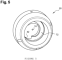
- FIG. 3 represents a rotor 46 of the vane pump 20.
- the rotor 46 is integral with the shaft 12.
- the rotor 46 and the externally toothed rotor 30 of the trochoid pump 22 are therefore driven in rotation relative to the housing 14 around the shaft 16 by the same shaft 12.
- the rotor 46 of the vane pump 20 can be made directly with the shaft 12 or made in a separate mechanical part, as shown in the figures. figure 1 And 3 .
- the rotor 46 is immobilized with respect to the shaft 12 for example by means of a key 48.
- the separate production of the shaft 12 and the rotor 46 makes it possible to avoid making a shaft 12 that is too complex.
- the rotor 46 rotates in a cavity 50 forming the stator of the vane pump 20.
- the cavity 50 has a shape of revolution around the axis 16.
- the cavity 50 is made in the transition piece 28 It is recalled that the transition piece 28 and the flanges 14a, 14b are integral with each other.
- Rotor 46 includes several propeller-shaped blades.
- the rotor 46 comprises four blades 52, 54, 56 and 58.
- Another number of blades can be envisaged. The number of blades depends in particular on the desired pitch of the propeller. This pitch can be fixed and identical for all the blades.
- the pitch of the propeller can then increase towards the outlet of the vane pump 20 in order to increase the fluid pressure gradually before reaching the trochoid pump 22.
- picture 3 the variation in pitch can be visualized by dimensions extending parallel to the axis 16.
- a first dimension c1 separates the vanes 52 and 54 as close as possible to the inlet duct 24 and a second dimension c2, greater than the dimension c1, separates the blades 54 and 56 closer to the opening 42 made in the transition piece 28.
- FIG. 4 represents an example of the profile of the blades 52, 54, 56 and 58.
- This profile is a section of a blade by a cylindrical surface 60 of axis 16 represented flat.
- the profile extends between a leading edge 62 located closest to the inlet duct 24 and a trailing edge 64 located closest to the transition piece 28.
- the profile is asymmetrical. More specifically, an extrados line 66 is longer than a corresponding intrados line 68.
- the designations of intrados and extrados are defined by similarity to those used for an airplane wing.
- the lower surface corresponds to the face of the blade where the fluid pressure is the highest and the upper surface corresponds to the face of the blade where the fluid pressure is the lowest.
- the cavity 50 forming the stator of the vane pump 20 is of revolution around the axis 16. Between the vanes 52, 54, 56, 58 and the cavity 50, a functional clearance is provided to allow rotation of the vanes. This functional clearance is as low as possible to limit leaks and improve the efficiency of the vane pump 20.
- the functional clearance is in particular a function of the manufacturing tolerances of the various mechanical parts and of the possible thermal expansions during operation. It is possible to produce a cylindrical cavity 50 over the entire length of the cavity 50 defined along the axis 26 and swept by the blades. Alternatively and advantageously, the section of the cavity 50, defined perpendicular to the axis 16, has a diameter D decreasing in the direction of the opening 42 forming the outlet of the vane pump 20.
- the decrease in diameter D is advantageously continuous in order to to limit load losses.
- the radial dimensions of the blades 52, 54, 56, 58 follow this decrease. It is considered that for any section, the nominal diameters of the blades and of the cavity 50 are equal to the functional clearances.
- This evolution of the diameter D makes it possible to reduce the passage section of the fluid from upstream to downstream of the vane pump 20. This reduction in passage section makes it possible to increase the speed of the fluid and therefore its pressure during its transit in the vane pump 20. This makes it possible to improve the efficiency of the vane pump 20.
- the rotor 46 of the vane pump 20 comprises a shaft 70 integral with the shaft 12.
- the shaft 70 and the shaft 12 can be made in a single mechanical part or two separate mechanical parts.
- the shaft 70 is of revolution around the axis 16. From the shaft 70 extend radially, around the axis 16, the vanes 52, 54, 56 and 58.
- the shaft 70 and the vanes 52, 54, 56, 58 form the rotor 46 of the vane pump 20.
- the outer diameter d of the shaft 70, defined perpendicular to the axis 16, can be constant over the entire area where the vanes 52, 54, 56 and 58 are implanted.
- the outer diameter d of the shaft 70 can increase in the direction of the outlet of the vane pump 20. This change in the diameter d of the shaft 70 contributes to the reduction in the fluid passage section in the direction of the outlet. of the vane pump 20.
- the outside diameter d increases continuously in the direction of the outlet of the vane pump 20 in order to limit pressure drops.
- the fluid is in direct contact on the one hand with the shaft 70 and on the other hand with the cavity 50.
- Increasing the diameter d of the shaft 70 and/or reducing the diameter D of the cavity 50 in the direction of the outlet of the vane pump 20 makes it possible to better adapt to the definition of the trochoid pump 22 and more precisely at the position of the opening 42 of the transition piece 28 forming both the outlet of the vane pump 20 and the suction zone 38 of the trochoid pump 22.
- the leading edge 62 of the blades 52, 54, 56 and 58 of the vane pump 20 can extend perpendicular to the axis 16. Alternatively, it is possible to incline the leading edge with respect to a direction perpendicular to axis 16. Specifically, leading edge 62 approaches the outlet of vane pump 20 as its distance from axis 16 increases. This inclination can be constant and the leading edge 62 can form a straight segment as shown in the picture 3 . The inclination of the line segment is represented by an angle a. It is also possible to tilt the leading edge 62 progressively when its distance from the axis 16 increases. This inclination makes it possible to improve the penetration of the fluid into the vane pump 20 to limit the risk of cavitation and its potentially destructive effects.
- the transition piece 28 comprises a ramp 72 making it possible to guide the fluid leaving the vane pump 20 before reaching the opening 42.
- the ramp 72 is located between the vane pump 20 and the trochoid pump 22 on the side of the vane pump 20.
- the fluid runs along the ramp 72 until reaching the opening 42.
- the ramp 72 is advantageously in the shape of a helix developing in the same direction as the helix shape of the blades 52, 54, 56 and 58 in order to limit the pressure losses between the two pumps 20 and 22.
Landscapes
- Engineering & Computer Science (AREA)
- Mechanical Engineering (AREA)
- General Engineering & Computer Science (AREA)
- Physics & Mathematics (AREA)
- Geometry (AREA)
- Details And Applications Of Rotary Liquid Pumps (AREA)
- Structures Of Non-Positive Displacement Pumps (AREA)
- Rotary Pumps (AREA)
Abstract
Description
- L'invention concerne une pompe hydraulique destinée à transformer de l'énergie mécanique en énergie hydraulique. Un fluide hydraulique véhiculé par la pompe hydraulique peut notamment être utilisé comme source d'énergie dans un moteur hydraulique ou plus simplement pour véhiculer du fluide, par exemple utilisé pour transporter de la chaleur ou pour lubrifier certains composants mécaniques. Plus précisément, certains organes, comme par exemple des machines électriques, ont besoin d'être refroidies lors de leur fonctionnement. Un fluide hydraulique peut circuler dans des parties d'une machine électrique pour y prélever de la chaleur et la transporter vers un échangeur pour y être évacuée.
- Les paramètres principaux à prendre en compte dans le choix d'une pompe hydraulique pour assurer la circulation de fluide sont : la pression et le débit. Ces deux paramètres sont bien entendu liés. En effet, pour une pompe donnée, on peut définir une courbe reliant ces deux paramètres pour une vitesse de rotation donnée. Le point de fonctionnement sur cette courbe est défini en fonction du circuit hydraulique et notamment de ses différences de hauteur et de ses pertes de charge.
- Les pompes volumétriques à engrenages sont largement utilisées pour la circulation de fluide hydraulique. Elles délivrent un débit variant peu en fonction de la pression contrairement aux pompes centrifuges. Les pompes à engrenage sont plus simples et plus robustes que les pompes à piston.
- Dans la famille des pompes à engrenage, il est possible de distinguer les pompes à engrenage externe où deux roues à denture externe tournent dans une chambre et les pompes à engrenage interne possédant deux rotors imbriqués, l'un à denture interne et l'autre à denture externe engrenant l'un dans l'autre. Le rotor interne possède moins de dents que le rotor externe. Cette différence de nombre de dents permet de créer des cavités mobiles entre les dents, cavités qui déplacent le fluide. Les pompes à engrenage interne sont plus compactes que les pompes à engrenage externe. En effet, dans une pompe à engrenage externe, les deux roues dentées sont disposées côte à côte alors que dans une pompe à engrenage interne, les deux roues dentées sont disposées l'une dans l'autre. Dans une pompe à engrenage interne, il est possible de prévoir une excroissance du stator en forme de croissant séparant localement les deux rotors. Une pompe sans cette excroissance est souvent appelée pompe trochoïde ou « gerotor », l'appellation « gerotor » étant plus spécifique de la littérature anglo-saxonne.
- Dans certaines utilisations particulières, comme par exemple en aéronautique, la pression atmosphérique peut être très basse en haute altitude et entrainer des difficultés de maintien de la circulation du fluide. En effet, une partie du circuit, notamment présent dans une bâche servant de réservoir tampon peut être laissée à la pression environnante. En cas de vol en haute altitude, la faible pression peut entrainer le désamorçage de la pompe hydraulique. D'autres phénomènes indésirables tels de la cavitation que peuvent également apparaitre.
- Par ailleurs, les pompes à engrenage fonctionnent bien à basse vitesse. Cependant, en aéronautique, les turbopropulseurs fonctionnent dans des plages de vitesse très élevées, typiquement entre 12000 et 30000 tours par minute. A ce jour, pour entrainer une pompe hydraulique au moyen de l'arbre d'un turbopropulseur, il est nécessaire de prévoir un réducteur de vitesse.
- L'invention vise à pallier tout ou partie des problèmes cités plus haut en proposant une pompe hydraulique pouvant être directement entrainée, sans réducteur de vitesse par un arbre pouvant tourner à grande vitesse, typiquement jusqu'à 30000 tours par minute et pouvant fonctionner dans un environnement à très basse pression typiquement lorsque la pression atmosphérique correspond à une altitude supérieure à 10000 m.
- A cet effet, l'invention a pour objet une pompe hydraulique, comprenant :
- un carter,
- une pompe à aube comprenant un rotor mobile en rotation par rapport au carter autour d'un premier axe, le rotor comprenant plusieurs aubes en forme d'hélice,
- une zone de transition appartenant au carter, et possédant, du côté de la pompe à aube, une rampe en forme d'hélice se développant dans le même sens que la forme en hélice des aubes,
- une pompe trochoïde comprenant un rotor à denture externe solidaire du rotor de la pompe à aube, et un rotor à denture interne mobile en rotation par rapport au carter autour d'un second axe parallèle et décalé du premier axe, la pompe trochoïde étant alimentée par la pompe à aube au travers de la zone de transition en longeant la rampe.
- Un pas d'hélice des aubes, défini le long du premier axe, est avantageusement croissant en direction d'une sortie de la pompe à aube.
- Pour chaque aube, une ligne d'extrados est avantageusement plus longue qu'une ligne d'intrados correspondante, les lignes d'intrados et d'extrados étant définies toutes deux sur une même surface cylindrique autour du premier axe.
- Le stator de la pompe à aube peut comprendre une cavité dans laquelle le rotor de la pompe à aube tourne, une section de la cavité, et une section du rotor de la pompe à aube, possèdent avantageusement un diamètre décroissant en direction de la sortie de la pompe à aube, les sections étant définie perpendiculairement au premier axe.
- Le rotor de la pompe à aube peut comprendre un arbre s'étendant selon le premier axe, les aubes s'étendant principalement radialement autour de l'arbre de la pompe à aube, un diamètre de l'arbre de la pompe à aube, défini perpendiculairement au premier axe, croit avantageusement en direction de la sortie de la pompe à aube.
- Chacune des aubes possède avantageusement un bord d'attaque se rapprochant de la sortie de la pompe à aube lorsque sa distance au premier axe augmente.
- L'invention sera mieux comprise et d'autres avantages apparaîtront à la lecture de la description détaillée d'un mode de réalisation donné à titre d'exemple, description illustrée par le dessin joint dans lequel :
- la
figure 1 représente en coupe longitudinale un exemple de pompe hydraulique conforme à l'invention ; - la
figure 2 représente en coupe transversale une pompe trochoïde appartenant à la pompe de lafigure 1 ; - la
figure 3 représente en vue longitudinale le rotor d'une pompe à aubes appartenant à la pompe de lafigure 1 ; - la
figure 4 représente une forme asymétrique que peut prendre des aubes de la pompe à aube ; - la
figure 5 représente en perspective une pièce de transition appartenant à la pompe de lafigure 1 ; - Par souci de clarté, les mêmes éléments porteront les mêmes repères dans les différentes figures.
- L'exemple décrit se rapporte à une pompe hydraulique 10 destinée à être mise en œuvre dans le domaine aéronautique et principalement pour faire circuler un fluide hydraulique, notamment de l'huile permettant de refroidir une machine électrique entraînée par l'arbre d'un turbopropulseur. La pompe hydraulique 10 est entrainée directement, c'est-à-dire sans réducteur de vitesse, par l'arbre du turbopropulseur. Autrement dit, la pompe hydraulique 10 est destinée à fonctionner dans une plage de vitesse très élevée, pouvant typiquement atteindre une vitesse de l'ordre de 30000 tours par minutes.
- L'invention n'est pas limitée au domaine aéronautique et peut être mise en œuvre dans tout autre domaine. L'intérêt principal de l'invention reste la possibilité d'atteindre des vitesses de rotation très élevée et de permettre un fonctionnement dans un environnement où la pression d'entrée de la pompe peut descendre bien en dessous de la pression atmosphérique classique au niveau du sol.
- La
figure 1 représente un exemple de pompe hydraulique 10 conforme à l'invention. La pompe hydraulique 10 est entrainée par un arbre moteur 12 tournant par rapport à un carter 14 autour d'un axe 16. Lafigure 1 est une vue en coupe dans un plan contenant l'axe 16. Un palier à deux roulements 18 guide la rotation de l'arbre moteur 12 par rapport au carter 14 autour d'un axe 16. La pompe hydraulique 10 comprend deux pompes montées en série : une pompe à aube 20 et une pompe trochoïde 22. La pompe à aube 20 permet le gavage de la pompe trochoïde 22. La pompe à aube 20 et la pompe trochoïde 22 sont entraînées par le même arbre moteur 12. Sur lafigure 1 , on distingue un conduit d'admission 24 réalisé dans le carter 14 et formant l'entrée de la pompe à aube 20 et un conduit de refoulement 26, également réalisé dans le carter 14 et formant la sortie de la pompe trochoïde 22. Une pièce de transition 28 forme à la fois la sortie de pompe à aube 20 et l'entrée de la pompe trochoïde 22. En pratique, le carter 14 peut être réalisé en plusieurs pièces mécaniques, deux dans l'exemple représenté : un premier flasque 14a et un second flasque 14b. La pièce de transition 28 est imbriquée dans la flasque 14a. Il est également possible d'imbriquer la pièce de transition 28 dans le flasque 14b. Les deux flasques 14a et 14b ainsi que la pièce de transition 28 sont tous trois solidaires les uns des autres. Tout autre type de maintien en position des flasques 14a, 14b et de la pièce de transition 28 est possible dans le cadre de l'invention. Pour faciliter la fabrication où l'assemblage des flasques 14a, 14b et de la pièce de transition 28, il est possible de prévoir de remplir les fonctions de ces pièces en un plus grand nombre ou un plus petit nombre de pièces mécaniques. Par la suite, on ne distinguera pas les deux flasques 14a, 14b et la pièce de transition 28 qui conjointement forment le carter 14. La fonction remplie par la pièce de transition 28 sera appelée zone de transition 28 du carter 14. - La
figure 2 représente la pompe trochoïde 22 en coupe dans un plan perpendiculaire à l'axe 16. La pompe trochoïde 22 comprend un rotor à denture externe 30 entrainé en rotation par l'arbre 12 autour de l'axe 16. Le rotor à denture externe 30 est solidaire de l'arbre 12. En pratique, le rotor à denture externe 30 et l'arbre 12 peuvent être réalisés dans une même pièce mécanique. La pompe trochoïde 22 comprend également un rotor à denture interne 32 pouvant tourner librement dans le carter 14 autour d'un axe 34 décalé de l'axe 12 et parallèle à celuici. Le carter 14 comprend une cavité cylindrique 36 d'axe 34 formant le stator de la pompe trochoïde 22. - Le rotor à denture externe 30 comprend six dents et le rotor à denture interne 32 comprend sept dents dans l'exemple représenté. Le rotor à denture externe 30 entraine en rotation le rotor à denture interne 32. De façon plus générale, le rotor à denture externe 30 comprend moins de dents que le rotor à denture interne 32. La différence de nombre de dents crée un espace interdentaire qui aspire le fluide dans une zone 38 où les dents se séparent et le refoule dans une zone 40 où les dents se rejoignent lors de la rotation des deux rotors 30 et 32. Sur la
figure 2 , les zones d'aspiration et de refoulement sont représentées respectivement à droite et à gauche de la figure. En pratique, la zone d'aspiration 38 correspond à une ouverture 42 réalisée dans la zone de transition 28 et la zone de refoulement 40 correspond à une ouverture 44 réalisée dans le carter 14 et communiquant avec le conduit de refoulement 26. - La
figure 3 représente un rotor 46 de la pompe à aube 20. Le rotor 46 est solidaire de l'arbre 12. Le rotor 46 et le rotor à denture externe 30 de la pompe trochoïde 22 sont donc entrainés en rotation par rapport au carter 14 autour de l'axe 16 par le même arbre 12. Le rotor 46 de la pompe à aube 20 peut être directement réalisé avec l'arbre 12 ou réalisé dans une pièce mécanique séparée, comme représenté sur lesfigures 1 et3 . Le rotor 46 est immobilisé par rapport à l'arbre 12 par exemple au moyen d'une clavette 48. La réalisation séparée de l'arbre 12 et du rotor 46 permet d'éviter de réaliser un arbre 12 trop complexe. - Le rotor 46 tourne dans une cavité 50 formant le stator de la pompe à aube 20. La cavité 50 possède une forme de révolution autour de l'axe 16. Dans l'exemple représenté, la cavité 50 est réalisée dans la pièce de transition 28. On rappelle que la pièce de transition 28 et les flasques 14a, 14b sont solidaires les uns des autres.
- Le rotor 46 comprend plusieurs aubes en forme d'hélice. Dans l'exemple représenté, le rotor 46 comprend quatre aubes 52, 54, 56 et 58. Un autre nombre d'aubes peut être envisagé. Le nombre d'aubes dépend notamment du pas souhaité de l'hélice. Ce pas peut être fixe et identique pour toutes les aubes. Alternativement, il est avantageux de faire varier le pas d'hélice de chaque aube entre l'entrée et la sortie de la pompe à aube 20. Un pas plus faible en entrée permet d'éviter les variations brutales de pression du fluide entre le conduit d'admission 24 et les aubes. En effet, pour permettre à la pompe hydraulique 10 de fonctionner avec une pression de fluide faible au niveau du conduit d'admission 24, il est avantageux de limiter la variation de pression de fluide au niveau de l'entrée de la pompe à aube 20, notamment pour éviter le risque de cavitation. Le pas de l'hélice peut ensuite croitre en direction de la sortie de la pompe à aube 20 afin d'augmenter la pression de fluide progressivement avant d'atteindre la pompe trochoïde 22. Sur la
figure 3 , la variation de pas peut être visualisée par des cotes s'étendant parallèlement à l'axe 16. Une première cote c1 sépare les aubes 52 et 54 au plus près du conduit d'admission 24 et une seconde cote c2, supérieure à la cote c1, sépare les aubes 54 et 56 plus près de l'ouverture 42 réalisée dans la pièce de transition 28. - La
figure 4 représente un exemple de profil des aubes 52, 54, 56 et 58. Ce profil est une coupe d'une aube par une surface cylindrique 60 d'axe 16 représentée à plat. Le profil s'étend entre un bord d'attaque 62 situé au plus près du conduit d'admission 24 et un bord de fuite 64 situé au plus près de la pièce de transition 28. Le profil est asymétrique. Plus précisément, une ligne d'extrados 66 est plus longue qu'une ligne d'intrados 68 correspondante. Les appellations d'intrados et d'extrados sont définies par similitude avec celles utilisées pour une aile d'avion. L'intrados correspond à la face de l'aube où la pression du fluide est la plus élevée et l'extrados correspond à la face de l'aube où la pression du fluide est la plus basse. Parmi les profils asymétriques, il est possible de choisir un profil défini par « National Advisory Committee for Aeronautics » connu par son acronyme NACA. La mise en œuvre d'un tel profil asymétrique permet d'augmenter la vitesse de rotation de la pompe à aube 20 en limitant les risques de cavitation pour obtenir l'augmentation de pression et le débit souhaités. D'autres profils sont bien entendu possibles. - La cavité 50 formant le stator de la pompe à aube 20 est de révolution autour de l'axe 16. Entre les aubes 52, 54, 56, 58 et la cavité 50, un jeu fonctionnel est prévu pour permettre la rotation des aubes. Ce jeu fonctionnel est le plus faible possible pour limiter les fuites et améliorer le rendement de la pompe à aube 20. Le jeu fonctionnel est notamment fonction des tolérances de fabrication des différentes pièces mécaniques et des dilatations thermiques possibles lors du fonctionnement. Il est possible de réaliser une cavité 50 cylindrique sur toute la longueur de la cavité 50 définie le long de l'axe 26 et balayée par les aubes. Alternativement et avantageusement, la section de la cavité 50, définie perpendiculairement à l'axe 16, possède un diamètre D décroissant en direction de l'ouverture 42 formant la sortie de la pompe à aube 20. La décroissance du diamètre D est avantageusement continue afin de limiter les pertes de charge. Les dimensions radiales des aubes 52, 54, 56, 58 suivent cette décroissance. On considère que pour toute section, les diamètres nominaux des aubes et de la cavité 50 sont égaux aux jeux fonctionnels près. Cette évolution du diamètre D permet de réduire la section de passage du fluide de l'amont vers l'aval de la pompe à aube 20. Cette réduction de section de passage permet d'augmenter la vitesse du fluide et donc sa pression lors de son transit dans la pompe à aube 20. Ceci permet d'améliorer l'efficacité de la pompe à aube 20.
- Alternativement ou en complément à la forme de la cavité 50, il est également possible d'agir sur le diamètre intérieur des aubes. Plus précisément, le rotor 46 de la pompe à aube 20 comprend un arbre 70 solidaire de l'arbre 12. Comme on l'a vu précédemment, l'arbre 70 et l'arbre 12 peuvent être réalisés en une seule pièce mécanique ou en deux pièces mécaniques séparées. L'arbre 70 est de révolution autour de l'axe 16. De l'arbre 70 s'étendent radialement, autour de l'axe 16, les aubes 52, 54, 56 et 58. L'arbre 70 et les aubes 52, 54, 56, 58 forment le rotor 46 de la pompe à aube 20. Le diamètre extérieur d de l'arbre 70, défini perpendiculairement à l'axe 16, peut être constant sur toute la zone où les aubes 52, 54, 56 et 58 sont implantées. Alternativement, le diamètre extérieur d de l'arbre 70 peut croitre en direction de la sortie de la pompe à aube 20. Cette évolution du diamètre d de l'arbre 70 contribue à la réduction de section de passage du fluide en direction de la sortie de la pompe à aube 20. Avantageusement le diamètre extérieur d croit de façon continue en direction de la sortie de la pompe à aube 20 afin de limiter les pertes de charge.
- Dans la pompe à aube 20, le fluide est en contact direct d'une part avec l'arbre 70 et d'autre part avec la cavité 50.
- Le fait d'augmenter le diamètre d de l'arbre 70 et/ou de réduire le diamètre D de la cavité 50 en direction de la sortie de la pompe à aube 20 permet de mieux s'adapter à la définition de la pompe trochoïde 22 et plus précisément à la position de l'ouverture 42 de la pièce de transition 28 formant à la fois la sortie de la pompe à aube 20 et la zone d'aspiration 38 de la pompe trochoïde 22.
- Le bord d'attaque 62 des aubes 52, 54, 56 et 58 de la pompe à aube 20 peut s'étendre perpendiculairement à l'axe 16. Alternativement, il est possible d'incliner le bord d'attaque par rapport à une direction perpendiculaire à l'axe 16. Plus précisément, le bord d'attaque 62 se rapproche de la sortie de la pompe à aube 20 lorsque sa distance à l'axe 16 augmente. Cette inclinaison peut être constante et le bord d'attaque 62 peut former un segment de droite comme représenté sur la
figure 3 . L'inclinaison du segment de droite est représentée par un angle a. Il est également possible d'incliner le bord d'attaque 62 de façon évolutive lorsque sa distance à l'axe 16 augmente. Cette inclinaison permet d'améliorer la pénétration du fluide dans la pompe à aube 20 pour limiter le risque de cavitation et ses effets potentiellement destructeurs. - La
figure 5 représente en perspective la pièce de transition 28. On distingue l'ouverture 42 formant la sortie de la pompe à aube 20 et la zone d'aspiration 38 de la pompe trochoïde 22. La pièce de transition 28 comprend une rampe 72 permettant de guider le fluide en sortie de la pompe à aube 20 avant d'atteindre l'ouverture 42. Autrement dit la rampe 72 est située entre la pompe à aube 20 et la pompe trochoïde 22 du côté de la pompe à aube 20. Le fluide longe la rampe 72 jusqu'à atteindre l'ouverture 42. La rampe 72 est avantageusement en forme en d'hélice se développant dans le même sens que la forme en hélice des aubes 52, 54, 56 et 58 afin de limiter les pertes de charges entre les deux pompes 20 et 22.
Claims (8)
- Pompe hydraulique, comprenant :- un carter (14),- une pompe à aube (20) comprenant un rotor (46) mobile en rotation par rapport au carter (14) autour d'un premier axe (16), le rotor (46) comprenant plusieurs aubes (52, 54, 56, 58) en forme d'hélice,- une zone de transition (28) appartenant au carter (14) et possédant, du côté de la pompe à aube (20), une rampe (72) en forme d'hélice se développant dans le même sens que la forme en hélice des aubes (52, 54, 56, 58),- une pompe trochoïde (22) comprenant un rotor à denture externe (30) solidaire du rotor (46) de la pompe à aube (20), et un rotor à denture interne (32) mobile en rotation par rapport au carter (14) autour d'un second axe (34) parallèle et décalé du premier axe (16), la pompe trochoïde (22) étant alimentée par la pompe à aube (20) au travers de la zone de transition (28) en longeant la rampe (72).
- Pompe hydraulique selon la revendication 1, dans laquelle un pas d'hélice des aubes (52, 54, 56, 58) étant défini le long du premier axe (16) est croissant en direction d'une sortie (42) de la pompe à aube (20).
- Pompe hydraulique selon l'une des revendications précédentes, dans laquelle pour chaque aube (52, 54, 56, 58), une ligne d'extrados (66) est plus longue qu'une ligne d'intrados (68) correspondante, les lignes d'intrados et d'extrados étant définies toutes deux sur une même surface cylindrique (60) autour du premier axe (16).
- Pompe hydraulique selon l'une des revendications précédentes, dans laquelle le stator de la pompe à aube (20) comprend une cavité (50) dans laquelle le rotor (46) de la pompe à aube (20) tourne, une section de la cavité, et une section du rotor (46) de la pompe à aube (20), possèdent un diamètre (D) décroissant en direction de la sortie (42) de la pompe à aube (20), les sections étant définie perpendiculairement au premier axe (16).
- Pompe hydraulique selon la revendication 4, dans laquelle le diamètre (D) décroit de façon continue.
- Pompe hydraulique selon l'une des revendications précédentes, dans laquelle le rotor (46) de la pompe à aube (20) comprend un arbre (70) s'étendant selon le premier axe (16), les aubes (52, 54, 56, 58) s'étendant principalement radialement autour de l'arbre (70) de la pompe à aube (20), un diamètre (d) de l'arbre (70) de la pompe à aube (20), défini perpendiculairement au premier axe (16), croit en direction de la sortie (42) de la pompe à aube (20).
- Pompe hydraulique selon la revendication 6, dans laquelle le diamètre (d) de l'arbre (70) croit de façon continue.
- Pompe hydraulique selon l'une des revendications précédentes, dans laquelle chacune des aubes (52, 54, 56, 58) possède un bord d'attaque (62) se rapprochant de la sortie (42) de la pompe à aube (20) lorsque sa distance au premier axe (16) augmente.
Applications Claiming Priority (1)
| Application Number | Priority Date | Filing Date | Title |
|---|---|---|---|
| FR2111834A FR3128976B1 (fr) | 2021-11-08 | 2021-11-08 | Pompe Hydraulique |
Publications (2)
| Publication Number | Publication Date |
|---|---|
| EP4177471A1 true EP4177471A1 (fr) | 2023-05-10 |
| EP4177471B1 EP4177471B1 (fr) | 2024-10-23 |
Family
ID=80786823
Family Applications (1)
| Application Number | Title | Priority Date | Filing Date |
|---|---|---|---|
| EP22205926.3A Active EP4177471B1 (fr) | 2021-11-08 | 2022-11-07 | Pompe hydraulique |
Country Status (3)
| Country | Link |
|---|---|
| US (1) | US12012956B2 (fr) |
| EP (1) | EP4177471B1 (fr) |
| FR (1) | FR3128976B1 (fr) |
Citations (3)
| Publication number | Priority date | Publication date | Assignee | Title |
|---|---|---|---|---|
| US20050191186A1 (en) * | 2003-06-09 | 2005-09-01 | Goodrich Control Systems Limited | Aeronautical generator |
| US20170211577A1 (en) * | 2014-08-04 | 2017-07-27 | Imo Industries, Inc. | Dual integrated organic working fluid pump |
| DE102018212497A1 (de) * | 2018-07-26 | 2020-01-30 | Eckerle Technologies GmbH | Fluidfördereinrichtung |
Family Cites Families (9)
| Publication number | Priority date | Publication date | Assignee | Title |
|---|---|---|---|---|
| US2713244A (en) * | 1951-12-20 | 1955-07-19 | Niles Bement Pond Co | Compound gear and centrifugal pump |
| US4789299A (en) * | 1987-10-30 | 1988-12-06 | Kris Demetrius | Liquid and air pump B |
| DE4038438A1 (de) * | 1990-12-01 | 1992-06-04 | Bosch Gmbh Robert | Aggregat zum foerdern von kraftstoff aus einem vorratstank zur brennkraftmaschine eines kraftfahrzeuges |
| US6247892B1 (en) * | 1999-07-26 | 2001-06-19 | Impsa International Inc. | Continuous flow rotary pump |
| PL196178B3 (pl) * | 2000-07-19 | 2007-12-31 | Zniszczynski Andrzej | Maszyna wirnikowo-wyporowa |
| PL214431B1 (pl) * | 2007-02-01 | 2013-07-31 | Andrzej Zniszczynski | Maszyna wirnikowo-wyporowa o sprężu wewnętrznym |
| WO2012053066A1 (fr) * | 2010-10-20 | 2012-04-26 | 日本オイルポンプ株式会社 | Dispositif de pompe |
| DE102017213507A1 (de) * | 2017-08-03 | 2019-02-07 | KSB SE & Co. KGaA | Laufrad für Abwasserpumpe |
| US20190345955A1 (en) * | 2018-05-10 | 2019-11-14 | Mp Pumps Inc. | Impeller pump |
-
2021
- 2021-11-08 FR FR2111834A patent/FR3128976B1/fr active Active
-
2022
- 2022-11-07 US US17/982,223 patent/US12012956B2/en active Active
- 2022-11-07 EP EP22205926.3A patent/EP4177471B1/fr active Active
Patent Citations (3)
| Publication number | Priority date | Publication date | Assignee | Title |
|---|---|---|---|---|
| US20050191186A1 (en) * | 2003-06-09 | 2005-09-01 | Goodrich Control Systems Limited | Aeronautical generator |
| US20170211577A1 (en) * | 2014-08-04 | 2017-07-27 | Imo Industries, Inc. | Dual integrated organic working fluid pump |
| DE102018212497A1 (de) * | 2018-07-26 | 2020-01-30 | Eckerle Technologies GmbH | Fluidfördereinrichtung |
Also Published As
| Publication number | Publication date |
|---|---|
| FR3128976A1 (fr) | 2023-05-12 |
| EP4177471B1 (fr) | 2024-10-23 |
| US20230151812A1 (en) | 2023-05-18 |
| US12012956B2 (en) | 2024-06-18 |
| FR3128976B1 (fr) | 2023-11-24 |
Similar Documents
| Publication | Publication Date | Title |
|---|---|---|
| WO2020084271A1 (fr) | Turbomachine à double hélices non carénées | |
| EP4073366B1 (fr) | Système propulsif aéronautique à faible débit de fuite et rendement propulsif amélioré | |
| BE1025560B1 (fr) | Procede de fabrication et groupe de lubrification pour turbomachine | |
| EP3610134A1 (fr) | Aube directrice, turbomachine et procédé de fabrication associés | |
| EP4073369A1 (fr) | Système propulsif aéronautique à rendement propulsif amélioré | |
| WO2019229362A1 (fr) | Aube de turbomachine comprenant un passage interne d'écoulement de fluide équipé d'une pluralité d'éléments perturbateurs à agencement optimisé | |
| WO2016116694A1 (fr) | Intégration d'une pompe en fût de pignon | |
| EP4177471B1 (fr) | Pompe hydraulique | |
| WO2021152230A1 (fr) | Circuit d'alimentation en carburant d'un moteur d'aeronef | |
| EP4073371A1 (fr) | Système propulsif aéronautique à faible débit de fuite et rendement propulsif amélioré | |
| EP4508311A1 (fr) | Pièce statorique à ailette dans une turbomachine | |
| FR3104644A1 (fr) | Système propulsif aéronautique à rendement propulsif amélioré | |
| BE1032247B1 (fr) | Ensemble statorique de turbomachine comportant des rangées d'aubes en tandem | |
| CA2585300C (fr) | Pompe mixte | |
| WO2026077713A1 (fr) | Désaérateur incurvé installé dans un reservoir d'huile pour turbomachine | |
| WO2025141263A1 (fr) | Mecanisme de reduction pour systeme propulsif aeronautique | |
| WO2025141262A1 (fr) | Mecanisme de reduction pour systeme propulsif aeronautique | |
| FR3009347A1 (fr) | Diffuseur pour un compresseur radial ou mixte d'un moteur comprenant un anneau et des actionneurs | |
| EP4229286A1 (fr) | Système propulsif aéronautique ayant un rendement propulsif amélioré | |
| FR3136504A1 (fr) | Elément abradable pour une turbine de turbomachine, comprenant des alvéoles présentant différentes inclinaisons | |
| WO2025141260A1 (fr) | Mecanisme de reduction pour systeme propulsif aeronautique | |
| WO2026017506A1 (fr) | Pompe à anneau liquide pour aéronef et procédé d'utilisation associé | |
| WO2025141261A1 (fr) | Mecanisme de reduction pour systeme propulsif aeronautique | |
| WO2025141264A1 (fr) | Mecanisme de reduction pour systeme propulsif aeronautique | |
| WO2025248198A1 (fr) | Boitier d'accessoires pour une turbomachine d'aeronef |
Legal Events
| Date | Code | Title | Description |
|---|---|---|---|
| PUAI | Public reference made under article 153(3) epc to a published international application that has entered the european phase |
Free format text: ORIGINAL CODE: 0009012 |
|
| STAA | Information on the status of an ep patent application or granted ep patent |
Free format text: STATUS: THE APPLICATION HAS BEEN PUBLISHED |
|
| AK | Designated contracting states |
Kind code of ref document: A1 Designated state(s): AL AT BE BG CH CY CZ DE DK EE ES FI FR GB GR HR HU IE IS IT LI LT LU LV MC ME MK MT NL NO PL PT RO RS SE SI SK SM TR |
|
| STAA | Information on the status of an ep patent application or granted ep patent |
Free format text: STATUS: REQUEST FOR EXAMINATION WAS MADE |
|
| 17P | Request for examination filed |
Effective date: 20231107 |
|
| RBV | Designated contracting states (corrected) |
Designated state(s): AL AT BE BG CH CY CZ DE DK EE ES FI FR GB GR HR HU IE IS IT LI LT LU LV MC ME MK MT NL NO PL PT RO RS SE SI SK SM TR |
|
| GRAP | Despatch of communication of intention to grant a patent |
Free format text: ORIGINAL CODE: EPIDOSNIGR1 |
|
| STAA | Information on the status of an ep patent application or granted ep patent |
Free format text: STATUS: GRANT OF PATENT IS INTENDED |
|
| INTG | Intention to grant announced |
Effective date: 20240527 |
|
| RAP1 | Party data changed (applicant data changed or rights of an application transferred) |
Owner name: SERV Owner name: THALES |
|
| RAP1 | Party data changed (applicant data changed or rights of an application transferred) |
Owner name: SERV Owner name: CETIM Owner name: THALES |
|
| GRAS | Grant fee paid |
Free format text: ORIGINAL CODE: EPIDOSNIGR3 |
|
| GRAA | (expected) grant |
Free format text: ORIGINAL CODE: 0009210 |
|
| STAA | Information on the status of an ep patent application or granted ep patent |
Free format text: STATUS: THE PATENT HAS BEEN GRANTED |
|
| AK | Designated contracting states |
Kind code of ref document: B1 Designated state(s): AL AT BE BG CH CY CZ DE DK EE ES FI FR GB GR HR HU IE IS IT LI LT LU LV MC ME MK MT NL NO PL PT RO RS SE SI SK SM TR |
|
| REG | Reference to a national code |
Ref country code: GB Ref legal event code: FG4D Free format text: NOT ENGLISH |
|
| REG | Reference to a national code |
Ref country code: CH Ref legal event code: EP |
|
| REG | Reference to a national code |
Ref country code: DE Ref legal event code: R096 Ref document number: 602022007032 Country of ref document: DE |
|
| REG | Reference to a national code |
Ref country code: IE Ref legal event code: FG4D Free format text: LANGUAGE OF EP DOCUMENT: FRENCH |
|
| REG | Reference to a national code |
Ref country code: LT Ref legal event code: MG9D |
|
| REG | Reference to a national code |
Ref country code: NL Ref legal event code: MP Effective date: 20241023 |
|
| REG | Reference to a national code |
Ref country code: AT Ref legal event code: MK05 Ref document number: 1735036 Country of ref document: AT Kind code of ref document: T Effective date: 20241023 |
|
| PG25 | Lapsed in a contracting state [announced via postgrant information from national office to epo] |
Ref country code: NL Free format text: LAPSE BECAUSE OF FAILURE TO SUBMIT A TRANSLATION OF THE DESCRIPTION OR TO PAY THE FEE WITHIN THE PRESCRIBED TIME-LIMIT Effective date: 20241023 |
|
| PG25 | Lapsed in a contracting state [announced via postgrant information from national office to epo] |
Ref country code: NL Free format text: LAPSE BECAUSE OF FAILURE TO SUBMIT A TRANSLATION OF THE DESCRIPTION OR TO PAY THE FEE WITHIN THE PRESCRIBED TIME-LIMIT Effective date: 20241023 |
|
| PG25 | Lapsed in a contracting state [announced via postgrant information from national office to epo] |
Ref country code: HR Free format text: LAPSE BECAUSE OF FAILURE TO SUBMIT A TRANSLATION OF THE DESCRIPTION OR TO PAY THE FEE WITHIN THE PRESCRIBED TIME-LIMIT Effective date: 20241023 Ref country code: PT Free format text: LAPSE BECAUSE OF FAILURE TO SUBMIT A TRANSLATION OF THE DESCRIPTION OR TO PAY THE FEE WITHIN THE PRESCRIBED TIME-LIMIT Effective date: 20250224 Ref country code: IS Free format text: LAPSE BECAUSE OF FAILURE TO SUBMIT A TRANSLATION OF THE DESCRIPTION OR TO PAY THE FEE WITHIN THE PRESCRIBED TIME-LIMIT Effective date: 20250223 |
|
| PG25 | Lapsed in a contracting state [announced via postgrant information from national office to epo] |
Ref country code: FI Free format text: LAPSE BECAUSE OF FAILURE TO SUBMIT A TRANSLATION OF THE DESCRIPTION OR TO PAY THE FEE WITHIN THE PRESCRIBED TIME-LIMIT Effective date: 20241023 |
|
| PG25 | Lapsed in a contracting state [announced via postgrant information from national office to epo] |
Ref country code: BG Free format text: LAPSE BECAUSE OF FAILURE TO SUBMIT A TRANSLATION OF THE DESCRIPTION OR TO PAY THE FEE WITHIN THE PRESCRIBED TIME-LIMIT Effective date: 20241023 |
|
| PG25 | Lapsed in a contracting state [announced via postgrant information from national office to epo] |
Ref country code: ES Free format text: LAPSE BECAUSE OF FAILURE TO SUBMIT A TRANSLATION OF THE DESCRIPTION OR TO PAY THE FEE WITHIN THE PRESCRIBED TIME-LIMIT Effective date: 20241023 |
|
| PG25 | Lapsed in a contracting state [announced via postgrant information from national office to epo] |
Ref country code: NO Free format text: LAPSE BECAUSE OF FAILURE TO SUBMIT A TRANSLATION OF THE DESCRIPTION OR TO PAY THE FEE WITHIN THE PRESCRIBED TIME-LIMIT Effective date: 20250123 |
|
| PG25 | Lapsed in a contracting state [announced via postgrant information from national office to epo] |
Ref country code: LV Free format text: LAPSE BECAUSE OF FAILURE TO SUBMIT A TRANSLATION OF THE DESCRIPTION OR TO PAY THE FEE WITHIN THE PRESCRIBED TIME-LIMIT Effective date: 20241023 Ref country code: GR Free format text: LAPSE BECAUSE OF FAILURE TO SUBMIT A TRANSLATION OF THE DESCRIPTION OR TO PAY THE FEE WITHIN THE PRESCRIBED TIME-LIMIT Effective date: 20250124 Ref country code: AT Free format text: LAPSE BECAUSE OF FAILURE TO SUBMIT A TRANSLATION OF THE DESCRIPTION OR TO PAY THE FEE WITHIN THE PRESCRIBED TIME-LIMIT Effective date: 20241023 |
|
| PG25 | Lapsed in a contracting state [announced via postgrant information from national office to epo] |
Ref country code: PL Free format text: LAPSE BECAUSE OF FAILURE TO SUBMIT A TRANSLATION OF THE DESCRIPTION OR TO PAY THE FEE WITHIN THE PRESCRIBED TIME-LIMIT Effective date: 20241023 |
|
| PG25 | Lapsed in a contracting state [announced via postgrant information from national office to epo] |
Ref country code: RS Free format text: LAPSE BECAUSE OF FAILURE TO SUBMIT A TRANSLATION OF THE DESCRIPTION OR TO PAY THE FEE WITHIN THE PRESCRIBED TIME-LIMIT Effective date: 20250123 |
|
| PG25 | Lapsed in a contracting state [announced via postgrant information from national office to epo] |
Ref country code: SM Free format text: LAPSE BECAUSE OF FAILURE TO SUBMIT A TRANSLATION OF THE DESCRIPTION OR TO PAY THE FEE WITHIN THE PRESCRIBED TIME-LIMIT Effective date: 20241023 |
|
| PG25 | Lapsed in a contracting state [announced via postgrant information from national office to epo] |
Ref country code: MC Free format text: LAPSE BECAUSE OF FAILURE TO SUBMIT A TRANSLATION OF THE DESCRIPTION OR TO PAY THE FEE WITHIN THE PRESCRIBED TIME-LIMIT Effective date: 20241023 |
|
| PG25 | Lapsed in a contracting state [announced via postgrant information from national office to epo] |
Ref country code: DK Free format text: LAPSE BECAUSE OF FAILURE TO SUBMIT A TRANSLATION OF THE DESCRIPTION OR TO PAY THE FEE WITHIN THE PRESCRIBED TIME-LIMIT Effective date: 20241023 |
|
| PG25 | Lapsed in a contracting state [announced via postgrant information from national office to epo] |
Ref country code: LU Free format text: LAPSE BECAUSE OF NON-PAYMENT OF DUE FEES Effective date: 20241107 |
|
| PG25 | Lapsed in a contracting state [announced via postgrant information from national office to epo] |
Ref country code: EE Free format text: LAPSE BECAUSE OF FAILURE TO SUBMIT A TRANSLATION OF THE DESCRIPTION OR TO PAY THE FEE WITHIN THE PRESCRIBED TIME-LIMIT Effective date: 20241023 |
|
| PG25 | Lapsed in a contracting state [announced via postgrant information from national office to epo] |
Ref country code: RO Free format text: LAPSE BECAUSE OF FAILURE TO SUBMIT A TRANSLATION OF THE DESCRIPTION OR TO PAY THE FEE WITHIN THE PRESCRIBED TIME-LIMIT Effective date: 20241023 |
|
| REG | Reference to a national code |
Ref country code: DE Ref legal event code: R097 Ref document number: 602022007032 Country of ref document: DE |
|
| PG25 | Lapsed in a contracting state [announced via postgrant information from national office to epo] |
Ref country code: SK Free format text: LAPSE BECAUSE OF FAILURE TO SUBMIT A TRANSLATION OF THE DESCRIPTION OR TO PAY THE FEE WITHIN THE PRESCRIBED TIME-LIMIT Effective date: 20241023 |
|
| PG25 | Lapsed in a contracting state [announced via postgrant information from national office to epo] |
Ref country code: CZ Free format text: LAPSE BECAUSE OF FAILURE TO SUBMIT A TRANSLATION OF THE DESCRIPTION OR TO PAY THE FEE WITHIN THE PRESCRIBED TIME-LIMIT Effective date: 20241023 |
|
| PG25 | Lapsed in a contracting state [announced via postgrant information from national office to epo] |
Ref country code: IT Free format text: LAPSE BECAUSE OF FAILURE TO SUBMIT A TRANSLATION OF THE DESCRIPTION OR TO PAY THE FEE WITHIN THE PRESCRIBED TIME-LIMIT Effective date: 20241023 |
|
| REG | Reference to a national code |
Ref country code: BE Ref legal event code: MM Effective date: 20241130 |
|
| PLBE | No opposition filed within time limit |
Free format text: ORIGINAL CODE: 0009261 |
|
| STAA | Information on the status of an ep patent application or granted ep patent |
Free format text: STATUS: NO OPPOSITION FILED WITHIN TIME LIMIT |
|
| PG25 | Lapsed in a contracting state [announced via postgrant information from national office to epo] |
Ref country code: SE Free format text: LAPSE BECAUSE OF FAILURE TO SUBMIT A TRANSLATION OF THE DESCRIPTION OR TO PAY THE FEE WITHIN THE PRESCRIBED TIME-LIMIT Effective date: 20241023 |
|
| 26N | No opposition filed |
Effective date: 20250724 |
|
| PG25 | Lapsed in a contracting state [announced via postgrant information from national office to epo] |
Ref country code: BE Free format text: LAPSE BECAUSE OF NON-PAYMENT OF DUE FEES Effective date: 20241130 |
|
| PG25 | Lapsed in a contracting state [announced via postgrant information from national office to epo] |
Ref country code: IE Free format text: LAPSE BECAUSE OF NON-PAYMENT OF DUE FEES Effective date: 20241107 |
|
| REG | Reference to a national code |
Ref country code: GB Ref legal event code: 732E Free format text: REGISTERED BETWEEN 20250925 AND 20251001 |
|
| PGFP | Annual fee paid to national office [announced via postgrant information from national office to epo] |
Ref country code: DE Payment date: 20251118 Year of fee payment: 4 |
|
| REG | Reference to a national code |
Ref country code: DE Ref legal event code: R081 Ref document number: 602022007032 Country of ref document: DE Owner name: SAFRAN ELECTRICAL & POWER, FR Free format text: FORMER OWNERS: SERV, LUCEAU, FR; THALES, MEUDON, FR Ref country code: DE Ref legal event code: R081 Ref document number: 602022007032 Country of ref document: DE Owner name: SERV, FR Free format text: FORMER OWNERS: SERV, LUCEAU, FR; THALES, MEUDON, FR |
|
| PGFP | Annual fee paid to national office [announced via postgrant information from national office to epo] |
Ref country code: FR Payment date: 20251125 Year of fee payment: 4 |
|
| PG25 | Lapsed in a contracting state [announced via postgrant information from national office to epo] |
Ref country code: HU Free format text: LAPSE BECAUSE OF FAILURE TO SUBMIT A TRANSLATION OF THE DESCRIPTION OR TO PAY THE FEE WITHIN THE PRESCRIBED TIME-LIMIT; INVALID AB INITIO Effective date: 20221107 |
|
| PG25 | Lapsed in a contracting state [announced via postgrant information from national office to epo] |
Ref country code: CY Free format text: LAPSE BECAUSE OF FAILURE TO SUBMIT A TRANSLATION OF THE DESCRIPTION OR TO PAY THE FEE WITHIN THE PRESCRIBED TIME-LIMIT; INVALID AB INITIO Effective date: 20221107 |