EP4177410A1 - Betongefäss mit rfid-etikett, verfahren zum lesen eines rfid-etiketts eines solchen behälters und verfahren zur herstellung eines solchen behälters - Google Patents
Betongefäss mit rfid-etikett, verfahren zum lesen eines rfid-etiketts eines solchen behälters und verfahren zur herstellung eines solchen behälters Download PDFInfo
- Publication number
- EP4177410A1 EP4177410A1 EP22204749.0A EP22204749A EP4177410A1 EP 4177410 A1 EP4177410 A1 EP 4177410A1 EP 22204749 A EP22204749 A EP 22204749A EP 4177410 A1 EP4177410 A1 EP 4177410A1
- Authority
- EP
- European Patent Office
- Prior art keywords
- rfid tag
- trench
- concrete
- tank
- concrete tank
- Prior art date
- Legal status (The legal status is an assumption and is not a legal conclusion. Google has not performed a legal analysis and makes no representation as to the accuracy of the status listed.)
- Granted
Links
Images
Classifications
-
- E—FIXED CONSTRUCTIONS
- E03—WATER SUPPLY; SEWERAGE
- E03F—SEWERS; CESSPOOLS
- E03F5/00—Sewerage structures
- E03F5/02—Manhole shafts or other inspection chambers; Snow-filling openings; accessories
Definitions
- the invention relates to a concrete tank provided with an RFID tag, to a method for reading an RFID tag in such a tank and to a method for manufacturing such a tank.
- the document US 7,777,628 proposes to install an RFID reader on top of a concrete tank. It is also known from documents KR101331873B1 , KR200437024Y1 And KR20200005205A installing an RFID tag in the cover of a concrete tank. A hole is formed in the outer face or in the inner face of the cover and an RFID tag encapsulated in a protective element is mounted on the cover. Once the cover has been formed with dry concrete, it is also proposed to form a hole in the cover to insert the RFID tag therein. All these solutions propose to identify a concrete tank by means of its cover. Unfortunately, covers age more quickly and/or are damaged more often, which limits the interest of an RFID tag attached to the cover. To track a concrete tank, hood tracking is not a good solution.
- the document US 8,149,121 proposes to encapsulate an RFID tag in a protective element in polyamide resin reinforced with glass fibres.
- the document US 8,807,873 describes a method of repairing a wall of a tank. The process proposes depositing a resin covering layer inside the tank in order to repair the latter.
- An object of the invention consists in providing a concrete tank which ensures the correct reading of an RFID tag, preferably up to about 5 meters deep and while remaining simple to implement.
- the concrete tank is remarkable in that it comprises an RFID tag enclosed in a liquid-tight radome, the radome being mounted flush with the bottom or embedded in the bottom, the RFID tag having at least one antenna disposed at a lower depth 100 mm from the bottom surface.
- the bottom of the radome is covered by a metal layer forming a reflector, the reflector being separated from the opening of the cover by at least one antenna.
- the direction of the antenna is perpendicular to the first direction.
- the RFID tag comprises a symmetrical antenna with two planar strands, the respective directions of which define an antenna plane perpendicular to the first direction.
- the bottom defines at least one trench.
- the RFID tag is outside the trench and is offset by a first distance relative to a side edge of the trench less than 40 mm, the trench having a depth at least equal to 20 mm and having first and second opposite ends.
- the at least one trench is a trench intended for the circulation of a liquid and the first and second opposite ends open into two separate through orifices in the side wall.
- the RFID tag is disposed respectively at first and second distances from the first and second ends of the at least one trench, the first and second ends opening into two separate portions of the side wall, the ratio between the first and second distances being between 0.8 and 1.2.
- the at least one trench is a rectilinear trench extending from one edge of the bottom to the other.
- the direction of the antenna is parallel to the longitudinal direction of the trench, the first distance being between 5 mm and 40 mm.
- the at least one trench is curved.
- the RFID tag is placed in the concave part of the at least one trench.
- the RFID tag is oriented so that the direction of its antenna is parallel to a tangent to the side edge of the trench, the first distance being between 5 mm and 40 mm.
- the RFID tag is equidistant from the two ends of the trench.
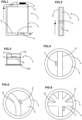
- FIG 1 illustrates a concrete tank 1 which is provided with an RFID tag 2.
- the concrete tank 1 comprises a bottom 3 made of concrete as well as a side wall 4 extending from the bottom 3 in a first direction Z to form a receptacle.
- the side wall 4 is made of concrete and it extends over a height of at least one meter from the bottom 3.
- the bottom 3 of the concrete tank 1 is the wall which extends mainly or exclusively perpendicular to the first direction Z.
- the side wall 4 extends exclusively or mainly in the first direction Z.
- the RFID tag 2 is a passive tag, i.e. a tag that receives energy from incident electromagnetic radiation and uses this energy to power an electronic device and generate outgoing electromagnetic radiation.
- the height of the side wall is less than 6 meters.
- the concrete tank 1 is mainly formed by concrete, that is to say the majority of which by weight is formed by concrete.
- the bottom 3 is preferably free of reinforcement.
- the side wall 4 is preferably free of reinforcement.
- the RFID tag 2 is placed in the bottom 3 of the tank 1 in an area where the quantity of concrete is sufficient (in particular the thickness) to support the installation of the RFID tag without degrading the mechanical performance.
- the installation of the RFID tag 2 in the bottom of the tank 1 also makes it possible not to modify the manufacturing process too much and thus limits the additional cost of this technical solution.
- the bottom 3 of the tank 1 can have any shape, for example circular, square or rectangular perpendicular to the first direction Z. The RFID tag 2 cannot be removed from the concrete tank 1.
- the concrete tank 1 is closed by a cover 5 which has a removable or pivoting cover (not shown).
- the cover 5 can be made of concrete, metal or plastic.
- RFID tag 2 comprises an electronic device 7 associated with at least one antenna 8, which is preferably a dipole antenna.
- the antenna 8 preferably comprises two symmetrical strands which extend from the electronic device 7 in an antenna direction Y. The two symmetrical antenna strands 8 are separated by the electronic device 7.
- the electronic device 7 and the two strands antenna 8 can be mounted on the support 9.
- the RFID tag 2 can have at least one piece of information representative of the concrete tank.
- This information is chosen from the date of installation of the tank, the date of manufacture of the tank, the configuration of the tank, the dimensions of the tank....
- the information relating to the configuration of the tank one can find the number of inlets/outlets, the height of the tank, the diameter of the tank.
- the RFID tag 2 has an antenna 8 which extends along an antenna direction Y.
- the antenna direction Y is perpendicular to the first direction Z.
- the antenna direction Y is parallel to the bottom 3 of the concrete tank 1 or substantially parallel to the bottom 3.
- the antenna 8 is advantageously planar.
- the plane AA defined by the planar antenna 8 is perpendicular to the first direction Z.
- a first option is to place the RFID tag 2 in the side wall 4 near the top of the concrete tank 1, near the cover 5.
- This technical solution is not satisfactory because it requires a substantial modification of the method of manufacturing the concrete tank 1.
- the attenuation of the electromagnetic signal remains high, which makes it complicated the reading of the signal without introducing the reader 6 into the tank 1.
- the cover 5 being distinct and independent from the rest of the concrete tank 1, the measurement becomes dependent on the configuration of the cover 5 used, in particular when the opening of the cover 5 is off center as shown in figure 1 .
- This solution is not acceptable.
- the height is measured along the first direction Z from the wall forming the bottom 3 to the opening of the cover 5.
- the RFID tag 2 is placed close to the top of the concrete tank 1 in a projecting area of the side wall 4.
- the technical solution is not satisfactory because it requires a substantial modification. of the method of manufacturing the concrete tank 1 and in particular of the mould, which leads to a substantial additional cost.
- the installation of the RFID tag 2 in concrete results in a significant attenuation of the electromagnetic signal received and emitted by the RFID tag 2 which makes it more difficult for an electromagnetic signal to be received by an RFID tag reader 6 .
- an RFID tag 2 installed in the bottom 3 of the concrete tank 1 has satisfactory attenuation of the electromagnetic signal.
- the electromagnetic signal emitted is compatible with a reading outside the concrete tank 1, in the immediate vicinity of the opening of the concrete tank 1.
- the reading can be carried out with a reader 6 which is between 50 cm and 1 m at the -above the opening of the cover 5, for example with a reader 6 held at arm's length with an operator standing or slightly leaning.
- the attenuation value is substantially identical to that measured for an RFID tag 2 placed in the top part of the side wall 4 and projecting inside the concrete tank 1. It is particularly advantageous to install the tag RFID 2 in the bottom 3 of the concrete tank 1 because this has a minimal influence on the mechanical performance of the concrete tank 1. This also makes it possible not to modify the manufacturing process of the concrete tank 1 too much. Installation of the RFID tag 2 in the bottom of the tank 1 makes the reading less sensitive to the configuration of the cover 5.
- the RFID tag 2 is installed in a radome 10 which is liquid-tight.
- a liquid-tight radome 10 makes it possible to protect the RFID tag 2 from the external environment and in particular from the components of the concrete or from the liquids and sludge which circulate in the tank 1.
- the radome 10 forms a closed receptacle which encloses the electronic device 7 and the antenna 8 away from the concrete.
- the cover of the radome 10 is made of a dielectric material which is transparent and allows the waves to pass in the wavelength range of the signal received and coming from the RFID tag 2.
- the material of the radome 10 is electrically insulating.
- the radome 10 is made in several parts which are fixed to each other so as to define a sealed box which contains the RFID tag 2.
- the entire radome 10 is made of ceramic and preferably of alumina.
- the cover, the rest of the case or the whole case can be formed from a polymeric material.
- the radome 10 is made for example of Acrylonitrile Butadiene Styrene (ABS).
- a film of air or of another gas or gaseous mixture is preferentially present between the antenna 8 and the concrete inside the radome 10.
- the pocket of gas between the antenna 8 and the concrete makes it possible not to attenuate the electromagnetic radiation to facilitate its propagation to the top of the concrete tank 1 and through the opening of the cover 5.
- a resin is introduced into the radome 10 to encapsulate the antenna 8 and the electronic device 7.
- the radome 10 is embedded in concrete, that is to say completely surrounded by concrete. It is advantageous for the RFID tag to be embedded in the bottom 3 to a depth of between 0 mm and 100 mm, preferably between 5 mm and 100 mm, preferably less than 80 mm and even more preferably less than 50 mm. In other words, the thickness of concrete to be traversed by the electromagnetic radiation between the antenna of the RFID tag 2 and the interior of the concrete tank 1 is less than 40 mm, preferably between 5 mm and 40mm. The penetration depth of the RFID tag 2 and the thickness of concrete covering the RFID tag 2 are measured in the first direction Z.
- the radome 10 is installed in the bottom 3 of the concrete tank 1 and the radome 10 has a face which is not covered by the concrete so as to facilitate the propagation of the signal.
- the radome 10 it is preferable to prevent the radome 10 from projecting from the bottom 3 of the tank 1. It is advantageous to provide that the radome 10 has a mounted face flush with the internal surface. concrete.
- the top of the radome 10 forms a depression in the bottom wall 3 of the tank 1. This configuration nevertheless tends to retain the sludge and liquids, which is detrimental to good circulation of the electromagnetic signal.
- the depth of penetration of the antenna 8 inside the radome 10 has a reduced effect on the gain and the impedance of the transmitted signal. It is therefore advantageous to install the radome 10 flush to reduce the influence of the depth of penetration of the antenna 8 with respect to the surface of the tank intended to receive the flows.
- the RFID tag 2 has at least one antenna 8 placed at a depth of between 5 mm and 40 mm relative to the surface of the bottom 3.
- the antenna does not project from the bottom 3 of the tank. 1 to avoid further deterioration, nor pressed too deeply which causes too much signal attenuation.
- the radome 10 In order to facilitate the installation and the maintenance in position of the radome 10, it is advantageous for one or more side walls of the radome 10 to have projecting elements. Once the concrete has hardened, the radome 10 can no longer be separated from the concrete tank.
- the radome 10 is a cylinder closed at both ends, for example a tube of circular section closed at both ends.
- the outer diameter of the radome 10 can be 3 cm.
- the radome 10 is a block, for example a straight block.
- a radome 10 having any shape is also possible, for example a parallelepiped. It is advantageous to increase as much as possible the dimension of the radome 10 perpendicular to the plane AA defined by the antenna 8. A compromise must be found between the size of the radome 10 which can modify the mechanical performance of the bottom 3 of the vessel by concrete 1 and improving the propagation of the electromagnetic signal.
- the concrete tank has a side wall 4 having a significant height, at least 1 meter, preferably at least 2 meters, or even 5 meters.
- the great height of the side wall 4 makes it more complicated for the reception of the signal by the RFID tag 2 as well as the reception of the signal emitted by the RFID tag 2 up to the RFID tag reader 6.
- results acceptable measurements have been obtained with an RFID tag placed in the bottom 3 of a concrete tank 1 having a side wall 4 five meters high and with a reading device 6 located outside the concrete tank 1, the lid being open.
- the RFID tag 2 is provided with a reflector 10a made of metallic material.
- the reflector 10a is separated from the opening of the tank 1 by the antenna 8 so that the electromagnetic signal arrives with a better signal/noise ratio as far as the RFID tag reader 6.
- the reflector 10a can be formed by a layer of metal on one face, for example the lower face of the radome 10 which encapsulates the RFID tag 2.
- the reflector 10a can be formed by a metal plate whose thickness is less than 5 mm.
- the metal plate can be glued, formed by metallization of the case or by any other suitable technique.
- the metal may be aluminum.
- the use of a reflector 10a makes it possible to reduce the thickness of the radome 10 receiving the RFID tag 2. It is advantageous to have a plane reflector 10a, preferentially parallel to the plane defined by the antennas, and even more preferentially formed on a flat radome bottom 10.
- the RFID tag 2 is fixed or formed on the cover of the radome 10.
- the cover possessing the RFID tag 2 is fixed to the rest of the radome 10.
- the antenna 8 of the RFID tag 2 is located as far as possible from the reflector 10a in order to favor obtaining a better gain for the transmitted signal.
- the antenna 8 is placed in the half of the cavity which is furthest from the reflector 10a, in a direction perpendicular to the plane defined by the reflector 10a.
- a simple way to increase the gain of the signal transmitted in the direction of the opening of the tank 1 is to increase the surface of the plane of the reflector 10a.
- the surface of the reflector 10a is at least equal to the footprint surface of the RFID tag 2, that is to say the total surface considering the tag as a solid surface from one end to the other.
- the surface area of the reflector 10a is at least equal to 1.15 times the footprint area of the RFID tag 2, or even 1.3 times the footprint area of the RFID tag 2.
- the radome 10 is in the form of a cylinder closed at both ends, and more preferably in the form of a straight block. It may be particularly advantageous to provide for the lower face of the radome 10 to extend beyond the side walls so as to define a peripheral step which goes completely around the radome 10. It is then preferable for the reflector 10a to cover the entire facial area lower part of the radome 10 which makes it possible to have a larger reflector plane 10a and to define a step which blocks the radome 10 in the concrete.
- the reflector 10a To artificially increase the surface of the reflector plane 10a, it is advantageous to cut the reflector 10a into two distinct surfaces having identical or substantially identical areas and to connect these two surfaces by an impedance which is configured to introduce a complex impedance value of preferably at least equal to 1nH.
- the impedance can be formed simply by a metal pad connected to the two metal surfaces.
- the central third of the bottom 3 corresponds to the third of the surface of the bottom 3 which is in the form of a circle which extends from the center of the bottom 3.
- the center can be the center of a circle, or the intersection of the diagonals of a quadrilateral one of another regular polyhedron or the barycenter of the section.
- Substantially flat means a bottom 3 whose center is slightly higher or slightly lower than the edge of the bottom 3.
- the bottom can also be wavy or it can have another form of texturing.
- the flat or substantially flat bottom 3 is preferably perpendicular to the first direction Z.
- the RFID tag 2 is offset from the center of the bottom 3 and the antenna direction Y is arranged parallel to the surface of the wall nearest side to channel the emitted electromagnetic signal.
- the antenna direction Y is parallel to the nearest face.
- the antenna direction Y is tangent to the nearest face.
- the antenna 8 is aligned along an antenna direction Y which is parallel or substantially parallel to the plane of the upper face of the bottom 3.
- a trench 11 in the bottom 3.
- the trench 11 is open on the bottom 3 of the tank 1 and it faces at least one antenna 8 perpendicular to the antenna direction Y and perpendicular to the first direction Z. It has been observed that in comparison with a tank 1 with a flat or substantially flat bottom 3, the formation of a trench 11 makes it possible to reduce the attenuation of the electromagnetic signal.
- RFID tag 2 is outside trench 11.
- the trench 11 has a depth in the bottom 3 which is at least equal to 10 mm and preferably at least equal to 40 mm. The depth is measured along the first direction Z. Preferably, the trench 11 sinks to a depth greater than the depth of the antenna 8 in the bottom 3 and even more preferably to a depth equal to the maximum penetration of the radome 10 into the bottom 3.
- the width of the trench 11 is at least equal to 10 mm and preferably at least equal to 40 mm.
- the section of the trench 11 can have any shape.
- the section of the trench 11 is square, rectangular, semi-circular or semi-circular extended by a rectangle.
- the antenna 8 is separated from the trench 11 by a thickness of concrete which is preferably between 10 mm and 40 mm.
- the concrete thickness is at least 10 mm between the face of the trench 11 and the outer wall of the radome 10.
- the RFID tag 2 is placed in the bottom 3 of the concrete tank 1 between two trenches 11 along the direction perpendicular to the first direction Z and preferably perpendicular to the antenna direction Y. Both trenches 11 make it possible to indicate the position of the RFID tag 2 in the bottom 3 which avoids damaging the antenna 8 in an a posteriori coring operation.
- the RFID tag 2 can also be surrounded by an annular trench 11, of any shape, preferably circular, square or rectangular.
- the trench 11 arranged close to the RFID tag 2 is a trench intended for the circulation of a fluid through the concrete tank.
- the trench 11 is intended for the circulation of a liquid and the first and second opposite ends of the trench lead to two separate through holes of the side wall 4.
- the side wall has two through holes in the extension of the trench which allows a liquid to pass through the side wall 4.
- the side wall 4 has no hole.
- it is thinned to facilitate the formation of holes of the correct size in the extension of the two ends of the trench 11.
- the RFID tag 2 is placed respectively at first and second distances from the first and second ends of the trench 11.
- the first and second ends open out into two separate portions of the side wall 4.
- the ratio between the first and second distances is between 0.8 and 1.2.
- the RFID tag 2 is equidistant from the two ends of the trench 11.
- the trench 11 is a rectilinear trench 11 extending from one edge to the other of the bottom 3.
- the trench 11 is arranged in a central position.
- the rectilinear trench 11 forms a diameter.
- the antenna direction Y is parallel to the longitudinal direction of the trench 11 and the first distance is less than 40 mm, preferably between 5 mm and 40 mm, or even between 10 mm and 40 mm.
- the bottom of the trench 11 has a plane of symmetry which passes through the center of the trench 11.
- the RFID tag 2 is installed at a distance from the plane of symmetry.
- the trench 11 is, in top view, curved.
- the RFID tag 2 is placed in the concave part of the bottom 3 delimited by the trench 11, that is to say inside the curve. As indicated above, the RFID tag 2 is placed close to the trench 11, outside the trench 11. In other words, the RFID tag 2 is disposed on the side of the trench 11 which has the center of curvature.
- the trench 11 being curved, there is a direction tangent to the side edge of the trench 11.
- the antenna direction Y is parallel to the direction tangent to the side edge of the trench 11.
- the RFID tag 2 is distant from the tangent to the lateral edge of the trench 11 by the first distance by a distance less than 40 mm, preferably between 5 mm and 40 mm.
- the bottom 3 of the concrete tank 1 comprises a plurality of trenches 11 which meet at one or more points. It is advantageous to place the RFID tag 2 close to a junction point of two trenches. As for the previous embodiments, it is advantageous to orient the antenna of the RFID tag so that the antenna direction Y is parallel to the side wall of the nearest trench 11 or to be tangent to this. side wall. It is preferable for the RFID tag to be placed in the concave portion of the curvature or of the equivalent curvature defined by the intersection of two trenches. It is preferable that the RFID tag 2 be placed as far as possible from the side wall 4.
- a reading was taken with good accuracy for a concrete tank 1 which has a height of 5 meters.
- the distance between the RFID tag 2 and the reader 6 is thus at least 5 meters.
- the concrete tank 1 is a tank for the flow of a liquid, for example rainwater or waste water, it is common for the water to carry solid elements, for example sludge.
- a layer of mud can be deposited on the upper surface of the bottom 3 of the concrete tank 1. This layer of mud generates an attenuation of the electromagnetic signal. It is therefore particularly advantageous for the upper surface of the bottom 3 of the concrete tank 1 to slope downwards from the side wall 4 to the trench 11 so that the layer of mud slides into the bottom of the trench 11 and is carried along. by the liquid which circulates along the trench 11.
- the concrete tank 1 has a top opening opposite the bottom 3 which has a section whose dimension is less than the dimension of the bottom 3.
- the bottom has a shape having a central symmetry, for example a bottom 3 circular, square or rectangular, it is advantageous that the center of the top opening is not aligned with the center of the bottom 3.
- the installation of the RFID tag 2 in the bottom of the concrete tank 1 is particularly advantageous because it does not require significantly modifying the manufacturing process of the concrete tanks 1. More advantageously, it does not require modifying the mold used to form the concrete tank 1.
- the manufacturing cost of such a concrete tank 1 is substantially equivalent to that of a concrete tank 1 without the RFID tag 2.
- the concrete tank 1 To make the concrete tank 1, at least one mold is provided, concrete not yet set, that is to say not yet solidified, that is to say in the liquid or pasty state, and a label RFID 2.
- the RFID tag is placed in the mold before pouring the concrete. Shims are placed in the mold to ensure that the label is in the correct position and with the correct orientation in the bottom of the tank.
- the vessel is made in at least two stages with a first casting step which forms part of the bottom.
- the RFID tag 2 is placed on the concrete in the liquid state in the desired position.
- the rest of the concrete is poured to form the bottom 3.
- the concrete is allowed to set.
- a reservation is made in the bottom during the formation of the concrete tank 1.
- the RFID tag 2 is placed in the reservation before being covered with concrete.
- the cover has a second RFID tag 12.
- the second RFID tag 12 is placed closer to the surface of the ground. This makes it possible to easily detect the concrete tank 1 when the tank is buried.
- the concrete thickness of the tank and the cover 5 block the electromagnetic radiation in the direction of the RFID tag 2 embedded in the bottom or arranged projecting from the side wall 4. It is then important to use another RFID tag 12 to ensure the location of the concrete tank embedded in the ground.
- the reading of the RFID tag 2 is carried out by providing a concrete tank 1 according to one of the preceding configurations.
- Cover 5 is open.
- the RFID tag reader 6 is arranged facing the opening of the cover 5 and facing the bottom 3.
- the RFID tag reader 6 emits an electromagnetic signal picked up by the tag RFID 2.
- the latter emits an electromagnetic signal picked up by the RFID tag reader 6.
- a second RFID tag 12 is placed in the cover 5.
- the RFID tag reader 6 carries out a first interrogation which makes it possible to detect the position of the concrete tank. Then the cover 5 is opened and a second interrogation is carried out by the RFID tag reader 6 to read the information from the tag located in the bottom of the tank.
Landscapes
- Health & Medical Sciences (AREA)
- Life Sciences & Earth Sciences (AREA)
- Engineering & Computer Science (AREA)
- Hydrology & Water Resources (AREA)
- Public Health (AREA)
- Water Supply & Treatment (AREA)
- Filling Or Discharging Of Gas Storage Vessels (AREA)
- Details Of Rigid Or Semi-Rigid Containers (AREA)
- Manufacturing Of Tubular Articles Or Embedded Moulded Articles (AREA)
Applications Claiming Priority (1)
| Application Number | Priority Date | Filing Date | Title |
|---|---|---|---|
| FR2111907A FR3128952B1 (fr) | 2021-11-09 | 2021-11-09 | Cuve en béton munie d’une étiquette rfid, procédé de lecture d’une étiquette rfid d’une telle cuve et procédé de fabrication d’une telle cuve |
Publications (3)
| Publication Number | Publication Date |
|---|---|
| EP4177410A1 true EP4177410A1 (de) | 2023-05-10 |
| EP4177410B1 EP4177410B1 (de) | 2024-07-31 |
| EP4177410C0 EP4177410C0 (de) | 2024-07-31 |
Family
ID=79831363
Family Applications (1)
| Application Number | Title | Priority Date | Filing Date |
|---|---|---|---|
| EP22204749.0A Active EP4177410B1 (de) | 2021-11-09 | 2022-10-31 | Betonschacht mit rfid-etikett, verfahren zum lesen eines rfid-etiketts eines solchen behälters und verfahren zur herstellung eines solchen behälters |
Country Status (2)
| Country | Link |
|---|---|
| EP (1) | EP4177410B1 (de) |
| FR (1) | FR3128952B1 (de) |
Citations (6)
| Publication number | Priority date | Publication date | Assignee | Title |
|---|---|---|---|---|
| KR200437024Y1 (ko) | 2006-12-28 | 2007-10-29 | 주식회사 셈즈 | 알에프아이디 태그가 내장된 안전맨홀 |
| US20090072978A1 (en) * | 2007-09-14 | 2009-03-19 | Tilson Jr Thomas M | Radio frequency identification system and method for use in cast concrete components |
| US8149121B2 (en) | 2008-05-21 | 2012-04-03 | Mitomo Corporation | Wireless identification tag |
| KR101331873B1 (ko) | 2013-07-11 | 2013-11-21 | 주식회사 동이산업개발 | Rfid 태그가 내장된 맨홀뚜껑 |
| US8807873B2 (en) | 2012-07-30 | 2014-08-19 | Lmk Technologies, Llc | Manhole liner having a wireless data transmitter |
| KR20200005205A (ko) | 2018-07-06 | 2020-01-15 | 유한회사 글로리아 | 스마트 맨홀 관리시스템을 위한 맨홀 뚜껑의 rfid 태그 장착구조 |
-
2021
- 2021-11-09 FR FR2111907A patent/FR3128952B1/fr active Active
-
2022
- 2022-10-31 EP EP22204749.0A patent/EP4177410B1/de active Active
Patent Citations (7)
| Publication number | Priority date | Publication date | Assignee | Title |
|---|---|---|---|---|
| KR200437024Y1 (ko) | 2006-12-28 | 2007-10-29 | 주식회사 셈즈 | 알에프아이디 태그가 내장된 안전맨홀 |
| US20090072978A1 (en) * | 2007-09-14 | 2009-03-19 | Tilson Jr Thomas M | Radio frequency identification system and method for use in cast concrete components |
| US7777628B2 (en) | 2007-09-14 | 2010-08-17 | Tilson Jr Thomas M | Radio frequency identification system and method for use in cast concrete components |
| US8149121B2 (en) | 2008-05-21 | 2012-04-03 | Mitomo Corporation | Wireless identification tag |
| US8807873B2 (en) | 2012-07-30 | 2014-08-19 | Lmk Technologies, Llc | Manhole liner having a wireless data transmitter |
| KR101331873B1 (ko) | 2013-07-11 | 2013-11-21 | 주식회사 동이산업개발 | Rfid 태그가 내장된 맨홀뚜껑 |
| KR20200005205A (ko) | 2018-07-06 | 2020-01-15 | 유한회사 글로리아 | 스마트 맨홀 관리시스템을 위한 맨홀 뚜껑의 rfid 태그 장착구조 |
Also Published As
| Publication number | Publication date |
|---|---|
| FR3128952A1 (fr) | 2023-05-12 |
| EP4177410B1 (de) | 2024-07-31 |
| EP4177410C0 (de) | 2024-07-31 |
| FR3128952B1 (fr) | 2024-03-08 |
Similar Documents
| Publication | Publication Date | Title |
|---|---|---|
| WO2017046245A1 (fr) | Pneumatique comprenant un transpondeur passif et procede de lecture des donnees | |
| FR3059605A1 (fr) | Enveloppe pneumatique equipee d''un organe electronique | |
| EP2448001A2 (de) | Optische Vorrichtung, Verfahren zu ihrer Herstellung und elektronischer Schaltkasten, der diese optische Vorrichtung enthält | |
| FR2826728A1 (fr) | Capteur de vitesse angulaire et procede de fabrication dudit capteur | |
| US9608029B2 (en) | Optical package with recess in transparent cover | |
| FR3047560A1 (fr) | Procede de fabrication d’un capteur de couple comprenant une etape d’encapsulation du circuit electronique du capteur. | |
| EP4177410B1 (de) | Betonschacht mit rfid-etikett, verfahren zum lesen eines rfid-etiketts eines solchen behälters und verfahren zur herstellung eines solchen behälters | |
| EP1813555A1 (de) | Verfahren zur Identifizierung eines Sammelbehälters mit Hilfe eines elektronischen Etiketts, das mit Funkwellen gelesen werden kann, und Unterlage zur Aufnahme eines solchen Etiketts | |
| FR2492114A1 (fr) | Reflecteur de rayonnement, notamment reflecteur solaire, poutre, procede de fabrication d'un support arriere pour un tel reflecteur et procede de fabrication d'un heliostat | |
| FR3061629A1 (fr) | Procede de fabrication d'un capot pour boitier electronique et boitier electronique comprenant un capot | |
| CN117981171A (zh) | 具有泡沫材料的空心波导组件 | |
| WO2019229389A1 (fr) | Enveloppe pneumatique equipee d'un systeme de mesure et methode de communication d'un tel assemblage | |
| FR2839391A1 (fr) | Balise de guidage et dispositif visuel la comportant | |
| WO2018154208A1 (fr) | Procédé de fabrication d'un capteur muni d'au moins une antenne ultra haute fréquence et capteur ultra haute fréquence ainsi obtenu | |
| FR2839208A1 (fr) | Reflecteur d'onde radio et structure comportant le reflecteur d'onde radio monte dessus | |
| EP2966599B1 (de) | Vorrichtung zum identifizieren eines elements aus beton | |
| EP4042058B1 (de) | Kanalabsperrvorrichtung mit einer messvorrichtung mit einem sender | |
| EP3505325B1 (de) | Einsatzhalterung für einspritzform eines sammelbeckens | |
| WO2010146533A1 (fr) | Antenne gsm, en particulier pour equipement utilisant le reseau public | |
| FR2938828A1 (fr) | Conteneur semi-enterre a jupe de protection | |
| FR3058876B1 (fr) | Capot pour recipient, notamment pour produit cosmetique, muni d'un espace de reception pour une puce electronique | |
| EP3200963B1 (de) | Bauelement mit einem elektronischen system und verfahren zur herstellung davon | |
| EP4045159B1 (de) | Klettergriff mit einem radiokfrequenzidentifikationselement | |
| EP3688235B1 (de) | Deckel für inspektionsschacht, durchlässig für radiowellen | |
| FR2817792A1 (fr) | Procede de fabrication d'un reservoir de stockage |
Legal Events
| Date | Code | Title | Description |
|---|---|---|---|
| PUAI | Public reference made under article 153(3) epc to a published international application that has entered the european phase |
Free format text: ORIGINAL CODE: 0009012 |
|
| STAA | Information on the status of an ep patent application or granted ep patent |
Free format text: STATUS: THE APPLICATION HAS BEEN PUBLISHED |
|
| AK | Designated contracting states |
Kind code of ref document: A1 Designated state(s): AL AT BE BG CH CY CZ DE DK EE ES FI FR GB GR HR HU IE IS IT LI LT LU LV MC ME MK MT NL NO PL PT RO RS SE SI SK SM TR |
|
| STAA | Information on the status of an ep patent application or granted ep patent |
Free format text: STATUS: REQUEST FOR EXAMINATION WAS MADE |
|
| 17P | Request for examination filed |
Effective date: 20231017 |
|
| RBV | Designated contracting states (corrected) |
Designated state(s): AL AT BE BG CH CY CZ DE DK EE ES FI FR GB GR HR HU IE IS IT LI LT LU LV MC ME MK MT NL NO PL PT RO RS SE SI SK SM TR |
|
| GRAP | Despatch of communication of intention to grant a patent |
Free format text: ORIGINAL CODE: EPIDOSNIGR1 |
|
| STAA | Information on the status of an ep patent application or granted ep patent |
Free format text: STATUS: GRANT OF PATENT IS INTENDED |
|
| RIC1 | Information provided on ipc code assigned before grant |
Ipc: E03F 5/02 20060101AFI20240306BHEP |
|
| INTG | Intention to grant announced |
Effective date: 20240320 |
|
| RIN1 | Information on inventor provided before grant (corrected) |
Inventor name: PHILIPPON, FRANCOIS Inventor name: BATEL, LOFTI |
|
| GRAS | Grant fee paid |
Free format text: ORIGINAL CODE: EPIDOSNIGR3 |
|
| GRAA | (expected) grant |
Free format text: ORIGINAL CODE: 0009210 |
|
| STAA | Information on the status of an ep patent application or granted ep patent |
Free format text: STATUS: THE PATENT HAS BEEN GRANTED |
|
| AK | Designated contracting states |
Kind code of ref document: B1 Designated state(s): AL AT BE BG CH CY CZ DE DK EE ES FI FR GB GR HR HU IE IS IT LI LT LU LV MC ME MK MT NL NO PL PT RO RS SE SI SK SM TR |
|
| REG | Reference to a national code |
Ref country code: CH Ref legal event code: EP Ref country code: GB Ref legal event code: FG4D Free format text: NOT ENGLISH |
|
| REG | Reference to a national code |
Ref country code: DE Ref legal event code: R096 Ref document number: 602022004971 Country of ref document: DE |
|
| REG | Reference to a national code |
Ref country code: IE Ref legal event code: FG4D Free format text: LANGUAGE OF EP DOCUMENT: FRENCH |
|
| U01 | Request for unitary effect filed |
Effective date: 20240807 |
|
| U07 | Unitary effect registered |
Designated state(s): AT BE BG DE DK EE FI FR IT LT LU LV MT NL PT RO SE SI Effective date: 20240902 |
|
| GRAT | Correction requested after decision to grant or after decision to maintain patent in amended form |
Free format text: ORIGINAL CODE: EPIDOSNCDEC |
|
| RAP4 | Party data changed (patent owner data changed or rights of a patent transferred) |
Owner name: COMMISSARIAT A L'ENERGIE ATOMIQUE ET AUX ENERGIESALTERNATIVES Owner name: RECO |
|
| U1H | Name or address of the proprietor changed after the registration of the unitary effect |
Owner name: COMMISSARIAT A L'ENERGIE ATOMIQUE ET AUX ENERGIESALTERNATIVES; FR Owner name: RECO; FR |
|
| U20 | Renewal fee for the european patent with unitary effect paid |
Year of fee payment: 3 Effective date: 20241025 |
|
| PG25 | Lapsed in a contracting state [announced via postgrant information from national office to epo] |
Ref country code: NO Free format text: LAPSE BECAUSE OF FAILURE TO SUBMIT A TRANSLATION OF THE DESCRIPTION OR TO PAY THE FEE WITHIN THE PRESCRIBED TIME-LIMIT Effective date: 20241031 |
|
| PG25 | Lapsed in a contracting state [announced via postgrant information from national office to epo] |
Ref country code: GR Free format text: LAPSE BECAUSE OF FAILURE TO SUBMIT A TRANSLATION OF THE DESCRIPTION OR TO PAY THE FEE WITHIN THE PRESCRIBED TIME-LIMIT Effective date: 20241101 Ref country code: PL Free format text: LAPSE BECAUSE OF FAILURE TO SUBMIT A TRANSLATION OF THE DESCRIPTION OR TO PAY THE FEE WITHIN THE PRESCRIBED TIME-LIMIT Effective date: 20240731 |
|
| PG25 | Lapsed in a contracting state [announced via postgrant information from national office to epo] |
Ref country code: IS Free format text: LAPSE BECAUSE OF FAILURE TO SUBMIT A TRANSLATION OF THE DESCRIPTION OR TO PAY THE FEE WITHIN THE PRESCRIBED TIME-LIMIT Effective date: 20241130 |
|
| PG25 | Lapsed in a contracting state [announced via postgrant information from national office to epo] |
Ref country code: HR Free format text: LAPSE BECAUSE OF FAILURE TO SUBMIT A TRANSLATION OF THE DESCRIPTION OR TO PAY THE FEE WITHIN THE PRESCRIBED TIME-LIMIT Effective date: 20240731 |
|
| PG25 | Lapsed in a contracting state [announced via postgrant information from national office to epo] |
Ref country code: RS Free format text: LAPSE BECAUSE OF FAILURE TO SUBMIT A TRANSLATION OF THE DESCRIPTION OR TO PAY THE FEE WITHIN THE PRESCRIBED TIME-LIMIT Effective date: 20241031 Ref country code: ES Free format text: LAPSE BECAUSE OF FAILURE TO SUBMIT A TRANSLATION OF THE DESCRIPTION OR TO PAY THE FEE WITHIN THE PRESCRIBED TIME-LIMIT Effective date: 20240731 |
|
| PG25 | Lapsed in a contracting state [announced via postgrant information from national office to epo] |
Ref country code: RS Free format text: LAPSE BECAUSE OF FAILURE TO SUBMIT A TRANSLATION OF THE DESCRIPTION OR TO PAY THE FEE WITHIN THE PRESCRIBED TIME-LIMIT Effective date: 20241031 Ref country code: PL Free format text: LAPSE BECAUSE OF FAILURE TO SUBMIT A TRANSLATION OF THE DESCRIPTION OR TO PAY THE FEE WITHIN THE PRESCRIBED TIME-LIMIT Effective date: 20240731 Ref country code: NO Free format text: LAPSE BECAUSE OF FAILURE TO SUBMIT A TRANSLATION OF THE DESCRIPTION OR TO PAY THE FEE WITHIN THE PRESCRIBED TIME-LIMIT Effective date: 20241031 Ref country code: IS Free format text: LAPSE BECAUSE OF FAILURE TO SUBMIT A TRANSLATION OF THE DESCRIPTION OR TO PAY THE FEE WITHIN THE PRESCRIBED TIME-LIMIT Effective date: 20241130 Ref country code: HR Free format text: LAPSE BECAUSE OF FAILURE TO SUBMIT A TRANSLATION OF THE DESCRIPTION OR TO PAY THE FEE WITHIN THE PRESCRIBED TIME-LIMIT Effective date: 20240731 Ref country code: GR Free format text: LAPSE BECAUSE OF FAILURE TO SUBMIT A TRANSLATION OF THE DESCRIPTION OR TO PAY THE FEE WITHIN THE PRESCRIBED TIME-LIMIT Effective date: 20241101 Ref country code: ES Free format text: LAPSE BECAUSE OF FAILURE TO SUBMIT A TRANSLATION OF THE DESCRIPTION OR TO PAY THE FEE WITHIN THE PRESCRIBED TIME-LIMIT Effective date: 20240731 |
|
| PG25 | Lapsed in a contracting state [announced via postgrant information from national office to epo] |
Ref country code: SM Free format text: LAPSE BECAUSE OF FAILURE TO SUBMIT A TRANSLATION OF THE DESCRIPTION OR TO PAY THE FEE WITHIN THE PRESCRIBED TIME-LIMIT Effective date: 20240731 |
|
| PG25 | Lapsed in a contracting state [announced via postgrant information from national office to epo] |
Ref country code: CZ Free format text: LAPSE BECAUSE OF FAILURE TO SUBMIT A TRANSLATION OF THE DESCRIPTION OR TO PAY THE FEE WITHIN THE PRESCRIBED TIME-LIMIT Effective date: 20240731 |
|
| PG25 | Lapsed in a contracting state [announced via postgrant information from national office to epo] |
Ref country code: SK Free format text: LAPSE BECAUSE OF FAILURE TO SUBMIT A TRANSLATION OF THE DESCRIPTION OR TO PAY THE FEE WITHIN THE PRESCRIBED TIME-LIMIT Effective date: 20240731 |
|
| PLBE | No opposition filed within time limit |
Free format text: ORIGINAL CODE: 0009261 |
|
| STAA | Information on the status of an ep patent application or granted ep patent |
Free format text: STATUS: NO OPPOSITION FILED WITHIN TIME LIMIT |
|
| PG25 | Lapsed in a contracting state [announced via postgrant information from national office to epo] |
Ref country code: MC Free format text: LAPSE BECAUSE OF FAILURE TO SUBMIT A TRANSLATION OF THE DESCRIPTION OR TO PAY THE FEE WITHIN THE PRESCRIBED TIME-LIMIT Effective date: 20240731 |
|
| 26N | No opposition filed |
Effective date: 20250501 |
|
| PG25 | Lapsed in a contracting state [announced via postgrant information from national office to epo] |
Ref country code: IE Free format text: LAPSE BECAUSE OF NON-PAYMENT OF DUE FEES Effective date: 20241031 |
|
| U20 | Renewal fee for the european patent with unitary effect paid |
Year of fee payment: 4 Effective date: 20251028 |
|
| PG25 | Lapsed in a contracting state [announced via postgrant information from national office to epo] |
Ref country code: HU Free format text: LAPSE BECAUSE OF FAILURE TO SUBMIT A TRANSLATION OF THE DESCRIPTION OR TO PAY THE FEE WITHIN THE PRESCRIBED TIME-LIMIT; INVALID AB INITIO Effective date: 20221031 |
|
| PG25 | Lapsed in a contracting state [announced via postgrant information from national office to epo] |
Ref country code: CY Free format text: LAPSE BECAUSE OF FAILURE TO SUBMIT A TRANSLATION OF THE DESCRIPTION OR TO PAY THE FEE WITHIN THE PRESCRIBED TIME-LIMIT; INVALID AB INITIO Effective date: 20221031 |
|
| REG | Reference to a national code |
Ref country code: CH Ref legal event code: H13 Free format text: ST27 STATUS EVENT CODE: U-0-0-H10-H13 (AS PROVIDED BY THE NATIONAL OFFICE) Effective date: 20260527 |
|
| PG25 | Lapsed in a contracting state [announced via postgrant information from national office to epo] |
Ref country code: TR Free format text: LAPSE BECAUSE OF FAILURE TO SUBMIT A TRANSLATION OF THE DESCRIPTION OR TO PAY THE FEE WITHIN THE PRESCRIBED TIME-LIMIT Effective date: 20240731 |
|
| PG25 | Lapsed in a contracting state [announced via postgrant information from national office to epo] |
Ref country code: ME Free format text: LAPSE BECAUSE OF FAILURE TO SUBMIT A TRANSLATION OF THE DESCRIPTION OR TO PAY THE FEE WITHIN THE PRESCRIBED TIME-LIMIT Effective date: 20240731 |
|
| PG25 | Lapsed in a contracting state [announced via postgrant information from national office to epo] |
Ref country code: CH Free format text: LAPSE BECAUSE OF NON-PAYMENT OF DUE FEES Effective date: 20251031 |