EP4177359A1 - Operation guidance method, method for operating blast furnace, method for manufacturing molten iron, operation guidance device - Google Patents
Operation guidance method, method for operating blast furnace, method for manufacturing molten iron, operation guidance device Download PDFInfo
- Publication number
- EP4177359A1 EP4177359A1 EP21838845.2A EP21838845A EP4177359A1 EP 4177359 A1 EP4177359 A1 EP 4177359A1 EP 21838845 A EP21838845 A EP 21838845A EP 4177359 A1 EP4177359 A1 EP 4177359A1
- Authority
- EP
- European Patent Office
- Prior art keywords
- furnace
- balance
- state
- derived
- oxygen
- Prior art date
- Legal status (The legal status is an assumption and is not a legal conclusion. Google has not performed a legal analysis and makes no representation as to the accuracy of the status listed.)
- Granted
Links
Images






Classifications
-
- C—CHEMISTRY; METALLURGY
- C21—METALLURGY OF IRON
- C21B—MANUFACTURE OF IRON OR STEEL
- C21B7/00—Blast furnaces
- C21B7/24—Test rods or other checking devices
-
- C—CHEMISTRY; METALLURGY
- C21—METALLURGY OF IRON
- C21B—MANUFACTURE OF IRON OR STEEL
- C21B5/00—Making pig-iron in the blast furnace
-
- C—CHEMISTRY; METALLURGY
- C21—METALLURGY OF IRON
- C21B—MANUFACTURE OF IRON OR STEEL
- C21B5/00—Making pig-iron in the blast furnace
- C21B5/006—Automatically controlling the process
-
- F—MECHANICAL ENGINEERING; LIGHTING; HEATING; WEAPONS; BLASTING
- F27—FURNACES; KILNS; OVENS; RETORTS
- F27D—DETAILS OR ACCESSORIES OF FURNACES, KILNS, OVENS OR RETORTS, IN SO FAR AS THEY ARE OF KINDS OCCURRING IN MORE THAN ONE KIND OF FURNACE
- F27D19/00—Arrangements of controlling devices
-
- C—CHEMISTRY; METALLURGY
- C21—METALLURGY OF IRON
- C21B—MANUFACTURE OF IRON OR STEEL
- C21B2300/00—Process aspects
- C21B2300/04—Modeling of the process, e.g. for control purposes; CII
-
- F—MECHANICAL ENGINEERING; LIGHTING; HEATING; WEAPONS; BLASTING
- F27—FURNACES; KILNS; OVENS; RETORTS
- F27D—DETAILS OR ACCESSORIES OF FURNACES, KILNS, OVENS OR RETORTS, IN SO FAR AS THEY ARE OF KINDS OCCURRING IN MORE THAN ONE KIND OF FURNACE
- F27D19/00—Arrangements of controlling devices
- F27D2019/0003—Monitoring the temperature or a characteristic of the charge and using it as a controlling value
-
- F—MECHANICAL ENGINEERING; LIGHTING; HEATING; WEAPONS; BLASTING
- F27—FURNACES; KILNS; OVENS; RETORTS
- F27D—DETAILS OR ACCESSORIES OF FURNACES, KILNS, OVENS OR RETORTS, IN SO FAR AS THEY ARE OF KINDS OCCURRING IN MORE THAN ONE KIND OF FURNACE
- F27D19/00—Arrangements of controlling devices
- F27D2019/0006—Monitoring the characteristics (composition, quantities, temperature, pressure) of at least one of the gases of the kiln atmosphere and using it as a controlling value
Definitions
- the present invention relates to an operation guidance method, a blast furnace operation method, a hot metal manufacturing method, and an operation guidance apparatus.
- a hot metal temperature and a hot metal production rate are important management indexes.
- hot metal making rate a hot metal temperature and a hot metal production rate
- An operator mainly operates blast air moisture and a pulverized coal ratio in order to control the hot metal temperature.
- it is required to perform the operation in compliance with a target hot metal making rate designated by a subsequent process.
- a blast air flow rate and an enriched oxygen flow rate are adjusted.
- the blast furnace process since the blast furnace process is operated in a state of being filled with a solid, the blast furnace process has characteristics that a heat capacity of an entire process is large and a time constant of a response to the operation (operational action) is long. Furthermore, there is a dead time to an extent of several hours until the raw material charged from an upper part (furnace top) of the blast furnace falls to a lower part (furnace bottom) of the blast furnace. Therefore, in order to properly operate the blast furnace, it is necessary to determine the operational action based on a future state of the blast furnace.
- Patent Literature 1 proposes a method for controlling the blast furnace based on future prediction using a physical model.
- a gas reduction speed parameter included in the physical model is adjusted so as to match a current gas composition in the furnace top, and a furnace heat is predicted using the physical model after adjusting the parameter.
- Patent Literature 1 JP H11-335710 A
- Patent Literature 1 predicts a hot metal temperature and a hot metal making rate based on a complicated mathematical formula such as a partial differential equation. Therefore, it is difficult to understand the calculation basis from a viewpoint of an operator engaged in the operation.
- the physical model has been a barrier in the reliable use of a control system.
- the present invention has been made in view of the above, and an object of the present invention is to provide an operation guidance method, a blast furnace operation method, a hot metal manufacturing method, and an operation guidance apparatus that can guide the operator to take an appropriate operational action in consideration of an in-furnace state.
- an operation guidance method includes: a first prediction step of predicting a state in a blast furnace when a current operation state is retained in a future, by using a physical model that is able to calculate the state in the blast furnace; and a display step of displaying, on an output device, an oxygen balance in a raceway region, a carbon balance in an entire furnace, and an oxygen balance derived from iron oxide in the entire furnace, when the state in the blast furnace is predicted.
- a current state and a state when the current operation state is retained in the future are displayed side by side in a comparable manner with respect to the oxygen balance in the raceway region, the carbon balance in the entire furnace, and the oxygen balance derived from iron oxide in the entire furnace.
- the operation guidance method according to the present invention further includes a second prediction step of predicting, by using the physical model, a future state in the blast furnace when an operation is performed under an arbitrary virtual operating condition which is input by an operator, wherein in the display step, the current state and a state when the operation is performed under the virtual operating condition are displayed side by side in a comparable manner on a graph with respect to the oxygen balance in the raceway region, the carbon balance in the entire furnace, and the oxygen balance derived from iron oxide in the entire furnace.
- the output device displays an input interface that is able to designate an arbitrary value of a plurality of operation variables indicating the operating condition, and the future state in the blast furnace is predicted based on the plurality of operation variables designated by the input interface.
- the oxygen balance in the raceway region indicates a relationship between a supply speed of oxygen blown into the raceway region and a consumption speed of carbon burned in the raceway region
- the carbon balance in the entire furnace indicates a relationship between a supply speed of carbon derived from coke supplied from a furnace top and a consumption speed of carbon burned in a furnace
- the oxygen balance derived from iron oxide in the entire furnace indicates a relationship among a charging speed of iron derived from iron oxide supplied from the furnace top, a charging speed of oxygen derived from iron oxide supplied from the furnace top, and a reduction reaction speed of iron oxide, by gas, supplied from the furnace top, and in the display step
- the oxygen balance in the raceway region, the carbon balance in the entire furnace, and the oxygen balance derived from iron oxide in the entire furnace, except for the charging speed of iron derived from iron oxide are displayed side by side in a first axis direction on the graph, and the charging speed of iron derived from iron oxide is displayed in a second axis direction ortho
- the display step includes displaying a heat balance in the furnace indicating a relationship between heat input into the furnace and heat consumed in the furnace, in addition to the oxygen balance in the raceway region, the carbon balance in the entire furnace, and the oxygen balance derived from iron oxide in the entire furnace.
- the display step displays each balance by converting each balance in terms of a value per unit weight of hot metal.
- a blast furnace operation method includes a step of controlling a blast furnace based on guidance according to the operation guidance method according to the present invention.
- a hot metal manufacturing method includes a step of manufacturing hot metal by controlling a blast furnace based on guidance according to the operation guidance method according to the present invention.
- an operation guidance apparatus includes: a prediction unit configured to predict a state in a blast furnace when a current operation state is retained in a future, by using a physical model that is able to calculate the state in the blast furnace; and a display unit configured to display an oxygen balance in a raceway region, a carbon balance in an entire furnace, and an oxygen balance derived from iron oxide in the entire furnace, when the state in the blast furnace is predicted.
- the operation guidance method, the blast furnace operation method, the hot metal manufacturing method, and the operation guidance apparatus according to the present invention display an oxygen balance in a raceway region, a carbon balance in an entire furnace, and an oxygen balance derived from iron oxide in the entire furnace when a state in the blast furnace is predicted. As a result, the operator is guided to take an appropriate operational action. Therefore, a highly efficient and stable operation of the blast furnace can be realized.
- An operation guidance apparatus 100 includes an information processing device 101, an input device 102, and an output device 103.
- the information processing device 101 is configured with a general-purpose device such as a personal computer or a workstation, and includes a RAM 111, a ROM 112, and a CPU 113.
- the RAM 111 temporarily stores a processing program and processing data related to processing executed by the CPU 113 and functions as a working area of the CPU 113.
- the ROM 112 stores a control program 112a for executing the operation guidance method according to the embodiment of the present invention, and the processing program and the processing data for controlling the entire operation of the information processing device 101.
- the CPU 113 controls the entire operation of the information processing device 101 according to the control program 112a and the processing program stored in the ROM 112.
- the CPU 113 functions as a first prediction unit that performs a first prediction step, a second prediction unit that performs a second prediction step, and a display unit that performs a display step in the operation guidance method to be described later.
- the input device 102 includes devices such as a keyboard, a mouse pointer, and a numeric keypad, and is operated to input various types of information to the information processing device 101.
- the output device 103 includes a display device, a printing device, and the like, and outputs various types of processed information of the information processing device 101.
- the output device 103 displays an oxygen balance in a raceway region, a carbon balance in an entire furnace, an oxygen balance derived from iron oxide in the entire furnace, a heat balance in the furnace, and the like in the operation guidance method to be described later.
- the "raceway region” refers to a region at about 2000°C where coke in the furnace is burned by oxygen in hot air blown from a tuyere.
- the physical model used in the present invention includes a partial differential equation group considering a plurality of physical phenomena such as reduction of iron ore, heat exchange between iron ore and coke, and melting of iron ore.
- the physical model used in the present invention is a physical model capable of calculating a variable (output variable) indicating a state in the blast furnace in a non-steady state (hereinafter referred to as a "dynamic model").
- a time step (time interval) for calculating the output variables is 30 minutes.
- the time step can be changed according to the purpose, and is not limited to the value of the present embodiment.
- the dynamic model described above can be expressed, for example, by the following formulas (1) and (2).
- x(t) is a state variable (temperature of coke or iron, oxidation degree of iron ore, descent rate of raw material, and the like) calculated in the dynamic model
- y(t) is a control variable such as a hot metal temperature (HMT) and the hot metal making rate.
- C is a matrix or a function for extracting the control variable from state variables calculated in the dynamic model.
- u(t) in the above formula (1) is an input variable in the dynamic model such as the blast air flow rate, the enriched oxygen flow rate, the pulverized coal flow rate, the blast air moisture, the blast temperature, and the coke ratio.
- the operation guidance method according to the present embodiment performs the first prediction step, the second prediction step, a balance calculation step, and the display step. Either the first prediction step or the second prediction step may be performed first. In addition, both the first prediction step and the second prediction step are not necessarily performed, and either one may be performed.
- the dynamic model described above is used to predict a state in the blast furnace at an arbitrary future time when the current operation state is retained in the future.
- Examples of the state in the blast furnace predicted in this step are the hot metal temperature, the hot metal making rate, air permeability of the blast furnace, and a pressure loss indicating a difference between the pressure at the furnace top and the pressure at the tuyere.
- the hot metal temperature and the hot metal making rate are predicted in this step will be described.
- a specific example of the first prediction step will be described later.
- the dynamic model described above is used to predict a future state inside the blast furnace when the operation is performed under arbitrary virtual operating conditions input by the operator.
- the output device 103 displays an input interface ( FIG. 15 ) that can designate arbitrary values of a plurality of operation variables indicating the operating conditions, and the state in the blast furnace at an arbitrary future time is predicted based on the values of the operation variables designated by the operator.
- FIG. 15 an input interface
- the hot metal temperature and the hot metal making rate are predicted in this step will be described.
- a specific example of the second prediction step will be described later.
- the material balance in the furnace includes the oxygen balance in the raceway region, the carbon balance in the entire furnace, and the oxygen balance derived from iron oxide in the entire furnace.
- the oxygen balance in the raceway region indicates a relationship between a supply speed of oxygen blown into the raceway region and a consumption speed of carbon burned in the raceway region ( FIG. 3 to be described later).
- the carbon balance in the entire furnace indicates a relationship between a supply speed of carbon derived from coke supplied from the furnace top and the consumption speed of carbon burned in the furnace ( FIG. 4 to be described later).
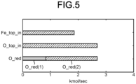
- the oxygen balance derived from iron oxide indicates a relationship among a charging speed of iron derived from iron oxide supplied from the furnace top, a charging speed of oxygen derived from iron oxide supplied from the furnace top, and a reduction reaction speed of iron oxide supplied from the furnace top by gas ( FIG. 5 to be described later).
- the heat balance in the furnace indicates a relationship between a heat input into the furnace and a heat consumed in the furnace ( FIG. 7 to be described later).
- this step calculates the current material balance and heat balance, the material balance and the heat balance at the arbitrary future time when the state in the blast furnace is predicted in the first prediction step, and the material balance and the heat balance at the arbitrary time when the state in the blast furnace is predicted in the second prediction step. Note that details of each balance calculated in the balance calculation step will be described later ( FIGS. 3 to 9 , FIGS. 11 to 14 , and FIGS. 15 to 19 to be described later).
- each balance calculated in the balance calculation step is displayed on the output device 103 and presented to the operator.
- the output device 103 displays the current material balance and the heat balance, the material balance and the heat balance at the arbitrary future time when the state in the blast furnace is predicted in the first prediction step, and the material balance and the heat balance at any future time when the state in the blast furnace is predicted in the second prediction step. Note that details of each balance calculated to display in the display step will be described later ( FIGS. 11 to 14 and FIGS. 16 to 19 described later).
- the oxygen balance in the raceway region, the carbon balance in the entire furnace, and the oxygen balance derived from iron oxide in the entire furnace are displayed in this step as follows.
- the current state and a state when the current operation state is retained in the future are displayed side by side in a comparable manner along a same axis direction in one graph in this step ( FIGS. 11 and 13 ).
- the oxygen balance in the raceway region, the carbon balance in the entire furnace, and the oxygen balance derived from iron oxide in the entire furnace are displayed in this step as follows.
- the current state and the state when the current operation state is retained in the future or the state when the operation is performed under the virtual operating conditions are displayed side by side in a graph in a comparable manner along the same axis direction in this step ( FIGS. 16 and 18 ).
- the material balance in the furnace when the operation is performed under the virtual operating conditions can be visually presented to the operator, so that the operator can be easily guided to take an appropriate operational action.
- the oxygen balance in the raceway region, the carbon balance in the entire furnace, and the oxygen balance derived from iron oxide in the entire furnace are displayed side by side in a first axis direction on the graph, except for the charging speed of iron derived from iron oxide.
- the charging speed of iron derived from iron oxide is displayed in a second axis direction orthogonal to the first axis direction ( FIGS. 11 , 13 , 16 , and 18 ).
- the following information may be displayed in addition to the oxygen balance in the raceway region, the carbon balance in the entire furnace, and the oxygen balance derived from iron oxide.
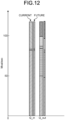
- the heat balance in the furnace indicating a relationship between the heat input into the furnace and the heat consumed in the furnace may be displayed on the output device 103 ( FIGS. 12 , 14 , 17 , and 19 ) and presented to the operator in this step. This makes it possible to visually present the heat balance in the furnace to the operator. Accordingly, the operator can be easily guided to take an appropriate operational action.
- the oxygen balance in the raceway region, the carbon balance in the entire furnace, the oxygen balance derived from iron oxide, and the heat balance in the furnace may be displayed per unit time ( FIGS. 11 , 12 , 16 , and 17 ).
- each balance may be converted and displayed per unit weight of hot metal ( FIGS. 14, 15 , 18 , and 19 ).
- an amount of pulverized coal, an amount of coke, an amount of solution loss carbon, and a sensible heat of hot metal and slag per unit weight of hot metal can be presented to the operator.
- Oxygen blown into the raceway region includes blast air (including enriched oxygen), blast air moisture, and oxygen in pulverized coal. Respective supply (charging) speeds [kmolO/sec] are defined as O_in(1), O_in(2), and O_in(3). Carbon burned in the raceway region is derived from coke or pulverized coal. Therefore, reaction between oxygen and carbon in the raceway region is represented by one of the following formulas (3) to (6).
- C (coke) + 1/2 O 2 CO (3)
- C (coke) + H 2 O CO + H 2 (4)
- C ( coal ) + 1/2 O 2 CO (5)
- C ( coal ) + O ( coal ) CO (6)
- a carbon consumption speed according to the above formula (3) is defined as C_out(1)
- a carbon consumption speed according to the above formula (4) is defined as C_out(2)
- carbon consumption speed according to the above formulas (5) and (6) are defined as C_out(3).
- the supply speed of oxygen [kmolO/sec] blown into the raceway region has to coincide with the consumption speed of carbon [kmolC/sec] as represented by the following formula (7) because a molar ratio of C to O is 1: 1.
- O _ in 1 + O _ in 2 + O _ in 2 C _ out 1 + C _ out 2 + C _ out 3
- FIG. 3 is a bar graph illustrating a balance relationship expressed by the above formula (7).
- a carbon consumption speed according to the above formula (8) is defined as C_out(4)
- carbon consumption speed according to the above formulas (9) to (12) are defined as C_out(5).
- supply speed of carbon supplied from furnace top the supply speed of carbon derived from coke supplied from the furnace top
- C_top_in the carbon consumption speed is equal to the carbon supply speed in the steady state, and the following formula (13) is established.
- C _ top _ in C _ out 1 + C _ out 2 + C _ out 4 + C _ out 5
- FIG. 4 is a bar graph illustrating a balance relationship between the carbon supply speed and the carbon consumption speed indicated by the above formula (13).
- C_top_in that is the supply speed of carbon supplied from the furnace top
- Fe_top_in that is a supply speed of Fe derived from iron oxide in the ore
- supply speed of Fe in ore a proportional relationship represented by the following Formula (14) is established between C_top_in and Fe_top_in by using a coke ratio CR [kg/t] that is the operation variable of the operator.
- Oxygen derived from iron oxide in the ore is reduced by any one of reactions represented by the following formulas (15) to (17).
- FeO + C Fe + CO
- FeO x + CO FeO x -1 + CO 2
- FeO x + H 2 O FeO x- 1 + H 2 O (17)
- reactions represented by the above formulas (9) and (10) also occur to restore CO 2 and H 2 O generated by the reactions represented by the above formulas (15) to (17) to CO and H 2 gases.
- supply speed of oxygen in ore the supply speed of oxygen derived from iron oxide in the ore
- FIG. 5 is a bar graph illustrating the supply speed of oxygen in the ore, the supply speed of Fe in the ore, and the gas reduction reaction speed.
- FIG. 6 is obtained by integrating the oxygen balance in the raceway region, the carbon balance derived from coke in the entire furnace, and the oxygen balance derived from iron oxide in the entire furnace illustrated in FIGS. 3 to 5 .
- FIG. 6 illustrates a value of the material balance in the furnace per unit time.
- a positive side indicates an increase of value in the furnace, and a negative side indicates a decrease of value in the tuyere.
- FIG. 6 is a bar graph illustrating the supply speed of oxygen in the ore, the supply speed of Fe in the ore, and the gas reduction reaction speed.
- FIG. 6 is obtained by integrating the oxygen balance in the raceway region, the carbon balance derived from coke in the entire furnace, and the oxygen balance derived from iron oxide in the entire furnace illustrated in FIGS. 3 to 5 .
- FIG. 6 illustrates a value of the material
- a line segment connecting respective balance values may be clearly indicated, or a meaning of an inclination of a line segment BE, which is the pulverized coal ratio PCR, may be clearly indicated in the graph.
- a line segment connecting respective balance values e.g., a line segment OG, a line segment AF, and a line segment BE
- a meaning of an inclination of a line segment BE which is the pulverized coal ratio PCR
- An inclination of a line segment AF in FIG. 6 is proportional to the coke ratio CR expressed by the above formula (14).
- An inclination of the line segment BE means the amount of carbon in the pulverized coal per charged iron mole, and is proportional to the pulverized coal ratio.
- an inclination of the line segment OG is a in the above formula (19), which means a proportional constant of Fe_top_in that is the supply speed of Fe in the ore and O_top_in that is the supply speed of oxygen in the ore.
- a line segment AB becomes long while a length of a line segment OB remains unchanged, so that the carbon consumption speed in the raceway region represented by a length of a line segment OA decreases. Therefore, a line segment CA corresponding to the supply speed of carbon supplied from the furnace top (C_top_in) is also shortened. As a result, a line segment CF corresponding to the supply speed of Fe in the ore supplied from the furnace top (Fe_top_in) is also shortened in proportion to the line segment CA, and thus the hot metal making rate decreases.
- Heat input into the furnace is derived from combustion heat of coke and pulverized coal at the tuyere, indirect reduction heat in the furnace, and blast sensible heat. These are defined as Q_in(1), Q_in(2), and Q_in(3), respectively.
- the heat consumed in the furnace is classified into sensible heat of hot metal and slag, direct reduction reaction heat, gasification reaction heat of coke due to blast air moisture, heat loss released from the furnace wall to cooling water or the atmosphere, sensible heat of gas discharged from the furnace top, and the like. These are respectively defined as Q_out(1), Q_out(2), Q_out(3), Q_out(4), and Q_out(5).
- FIG. 7 illustrates a value of the heat balance in the furnace per unit time.
- the heat balance in the furnace satisfies a relationship of the following formula (20) in the steady state.
- Q _ in 1 + Q _ in 2 + Q _ in 3 Q _ out 1 + Q _ out 2 + Q _ out 3 + Q _ out 4 + Q _ out 5
- the material balance and the heat balance in the furnace illustrated in FIGS. 6 and 7 are values per unit time
- a reduction material ratio that is an amount of carbon material per unit weight of hot metal, and the like it is necessary to obtain the material balance and the heat balance per unit weight of hot metal. Therefore, values obtained by dividing the variables illustrated in FIGS. 6 and 7 by Fe_top_in (the supply speed of Fe in the ore supplied from the furnace top) are illustrated in FIGS. 8 and 9 .
- an amount of pulverized coal, an amount of coke, an amount of solution loss carbon, and a sensible heat of hot metal and slag per unit weight of hot metal can be presented to the operator.
- a response y 0 of the control variable (here, the hot metal temperature and the hot metal making rate) obtained in this manner is referred to as a "free response" in the present embodiment.
- the free response of the hot metal making rate and the hot metal temperature when the operational action of increasing the coke ratio was carried out two hours before is indicated by solid lines in FIGS. 10(c) and 10(d) .
- the hot metal making rate decreases by about 1000 t/day, and the hot metal temperature increases by about 100°C.
- bar graphs of the material balance and the heat balance in the furnace state predicted in the first prediction step are arranged next to the bar graphs of the material balance and the heat balance in the furnace illustrated in FIGS. 8 and 9 .
- the left side indicates a value immediately before increasing the coke ratio (current state) in each of the bar graphs indicating O_in, C_out, C_top_in, C_out, O_top_in, O_red, Q_in, and Q_out.
- the right side of each bar graph indicates a value after 12 hours from the increase of the coke ratio.
- an upper graph is a value immediately before (current state) increasing the coke ratio
- a lower graph is a value 12 hours after increasing the coke ratio in bar graphs indicating Fe_top_in.
- a reason that a length of a line segment AE representing the hot metal making rate is decreased is that the inclination of the line segment AF proportional to the coke ratio has increased and a length of the line segment CA corresponding to the supply speed of carbon supplied from the furnace top (C_top_in) has shortened.
- the increase in the inclination of the line segment AF is a direct effect of increasing the coke ratio.
- the line segment AE corresponding to the hot metal making rate is shortened.
- the supply speed (O_top_in) of oxygen in the ore supplied from the furnace top decreases in proportion thereto, the consumption speed of carbon by direct reduction also decreases.
- FIGS. 13 and 14 illustrate results of converting the material balance and the heat balance in the furnace per unit time, illustrated in FIGS. 11 and 12 , into those per unit weight of hot metal.
- a line segment connecting respective balance values e.g., a line segment O'G', a line segment A'F', and a line segment B'E'
- a meaning of the line segment A'B', which is the pulverized coal ratio PCR may be clearly indicated in the graph.
- the line segment O'A' becomes longer after increasing the coke ratio. This means that since the coke ratio was increased, the amount of coke per unit weight of hot metal at a tuyere height has increased after undergoing direct reduction and carburization reaction in the furnace.
- the line segment A'B' indicating the pulverized coal ratio is also extended. This is because, similar to FIG. 11 , the pulverized coal amount per unit weight of hot metal has increased due to a decrease in the hot metal making rate while the pulverized coal flow rate remains unchanged.
- the second prediction step By performing the first prediction step described above and presenting the material balance and the heat balance in the furnace based on the results, it is possible to foresee future changes in the in-furnace state and control variables. However, it is necessary for the operator to take an appropriate operational action in response to the changes. For example, in FIG. 10 , it is predicted that the hot metal temperature will rise to near 1600°C, which is excessive. Therefore, by performing the second prediction step, the future material balance and heat balance in the furnace when the operator virtually changes the operation variable can also be presented.
- the pulverized coal flow rate is decreased to keep the hot metal temperature in an appropriate range at the timing two hours after the coke ratio is increased.
- the operator manipulates the value of the pulverized coal flow rate PCI in FIG. 15 to decrease the pulverized coal flow rate by 150 kg/min, and the results (response y 1 ) of predicting the hot metal making rate and the hot metal temperature by the above Formulas (23) and (24) are indicated by broken lines in FIGS. 10(c) and 10(d) .
- the hot metal temperature which was excessive due to the increase in the coke ratio, can be returned to an appropriate level.
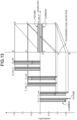
- FIGS. 16 to 19 are illustrated in FIGS. 16 to 19 .
- FIG. 16 is a graph illustrating the material balance in the furnace per unit time
- FIG. 17 is a graph illustrating the heat balance in the furnace per unit time
- FIG. 18 is a graph illustrating the material balance in the furnace per unit weight of hot metal
- FIG. 19 is a graph illustrating the heat balance in the blast furnace per unit time.
- each of graphs indicating O_in, C_out, C_top_in, C_out, O_top_in, O_ red, Q_in, and Q_out is a value immediately before increasing the coke ratio (current state).
- the right side of each of the graphs is a value after the virtual operational action is performed.
- an upper graph is a value immediately before (current state) increasing the coke ratio
- a lower graph is a value after performing the virtual operational action in the bar graphs indicating Fe_top_in.
- the hot metal making rate increases and the pulverized coal flow rate decreases, the inclination of the line segment BE in FIG. 16 representing the pulverized coal ratio and a length of a line segment A'B' in FIG. 18 decrease, and thus, an increase in sensible heat of hot metal and slag due to the increase in the coke ratio is compensated.
- the hot metal temperature can be maintained at a value substantially equivalent to the level before the increase in the coke ratio.
- FIGS. 16 to 19 exemplify a most typical operational action of decreasing the pulverized coal flow rate with respect to a decrease in the hot metal making rate and an increase in the hot metal temperature due to the increase in the coke ratio.
- a solution of a combined action by operation variables is also conceivable.
- the operation guidance method according to the present embodiment can also be applied to an operation method of the blast furnace.
- a step of controlling the blast furnace according to the guidance in the display step is included.
- the operation guidance method according to the present embodiment can also be applied to a hot metal manufacturing method.
- a step of manufacturing hot metal by controlling the blast furnace according to the guidance in the display step is performed.
- the operation guidance method, the blast furnace operation method, the hot metal manufacturing method, and the operation guidance apparatus according to the present embodiment as described above the oxygen balance in the raceway region, the carbon balance in the entire furnace, and the oxygen balance derived from iron oxide in the entire furnace when the state in the blast furnace is predicted are displayed. As a result, the operator is guided to take an appropriate operational action. Therefore, a highly efficient and stable operation of the blast furnace can be realized.
- the prediction result of the in-furnace state under the virtual operating conditions designated by the operator or the future prediction result without any operation can be presented together with the material balance and the heat balance.
- the operator can quantitatively and reasonably grasp the effect of the operational action and reach an appropriate operational action by himself/herself.
- the operation guidance method, the blast furnace operation method, the hot metal manufacturing method, and the operation guidance apparatus according to the present invention have been specifically described with reference to the embodiments and examples for carrying out the invention, the gist of the present invention is not limited to these descriptions and has to be broadly interpreted based on the description of the claims. It is obvious that various changes and modifications based on the descriptions are also included in the gist of the present invention.
Landscapes
- Engineering & Computer Science (AREA)
- Chemical & Material Sciences (AREA)
- Manufacturing & Machinery (AREA)
- Materials Engineering (AREA)
- Metallurgy (AREA)
- Organic Chemistry (AREA)
- Mechanical Engineering (AREA)
- General Engineering & Computer Science (AREA)
- Manufacture Of Iron (AREA)
- General Factory Administration (AREA)
- Manufacture Of Motors, Generators (AREA)
Abstract
Description
- The present invention relates to an operation guidance method, a blast furnace operation method, a hot metal manufacturing method, and an operation guidance apparatus.
- In a blast furnace process in the iron industry, a hot metal temperature and a hot metal production rate (hereinafter referred to as "hot metal making rate") are important management indexes. When the hot metal temperature increases, not only a surplus reduction material is consumed, but also descent of a raw material becomes unstable due to expansion of gas in a furnace. In addition, when the hot metal temperature extremely decreases, a slag discharging property is deteriorated, and a productivity of the blast furnace remarkably decreases. An operator mainly operates blast air moisture and a pulverized coal ratio in order to control the hot metal temperature. On the other hand, in the blast furnace, it is required to perform the operation in compliance with a target hot metal making rate designated by a subsequent process. In order to control the hot metal making rate, a blast air flow rate and an enriched oxygen flow rate are adjusted.
- In addition, since the blast furnace process is operated in a state of being filled with a solid, the blast furnace process has characteristics that a heat capacity of an entire process is large and a time constant of a response to the operation (operational action) is long. Furthermore, there is a dead time to an extent of several hours until the raw material charged from an upper part (furnace top) of the blast furnace falls to a lower part (furnace bottom) of the blast furnace. Therefore, in order to properly operate the blast furnace, it is necessary to determine the operational action based on a future state of the blast furnace.
- For this reason,
Patent Literature 1 proposes a method for controlling the blast furnace based on future prediction using a physical model. In the method for controlling the blast furnace described inPatent Literature 1, a gas reduction speed parameter included in the physical model is adjusted so as to match a current gas composition in the furnace top, and a furnace heat is predicted using the physical model after adjusting the parameter. - Patent Literature 1:
JP H11-335710 A - However, the physical model used in
Patent Literature 1 predicts a hot metal temperature and a hot metal making rate based on a complicated mathematical formula such as a partial differential equation. Therefore, it is difficult to understand the calculation basis from a viewpoint of an operator engaged in the operation. The physical model has been a barrier in the reliable use of a control system. - In addition, there is a phenomenon that is difficult to predict by the current physical model, such as blow-through of furnace gas due to deterioration of air permeability caused by powderization of raw materials and generation of unburned pulverized coal, and thus it is currently difficult to achieve complete automation of the blast furnace operation. Therefore, it is considered that a human machine cooperation technology for enhancing skills of the operator is also necessary. However, the control system based on the physical model as described above cannot sufficiently cope with this problem.
- The present invention has been made in view of the above, and an object of the present invention is to provide an operation guidance method, a blast furnace operation method, a hot metal manufacturing method, and an operation guidance apparatus that can guide the operator to take an appropriate operational action in consideration of an in-furnace state.
- To solve the problem and achieve the object, an operation guidance method according to the present invention includes: a first prediction step of predicting a state in a blast furnace when a current operation state is retained in a future, by using a physical model that is able to calculate the state in the blast furnace; and a display step of displaying, on an output device, an oxygen balance in a raceway region, a carbon balance in an entire furnace, and an oxygen balance derived from iron oxide in the entire furnace, when the state in the blast furnace is predicted.
- Moreover, in the operation guidance method according to the present invention, in the display step, a current state and a state when the current operation state is retained in the future are displayed side by side in a comparable manner with respect to the oxygen balance in the raceway region, the carbon balance in the entire furnace, and the oxygen balance derived from iron oxide in the entire furnace.
- Moreover, the operation guidance method according to the present invention further includes a second prediction step of predicting, by using the physical model, a future state in the blast furnace when an operation is performed under an arbitrary virtual operating condition which is input by an operator, wherein in the display step, the current state and a state when the operation is performed under the virtual operating condition are displayed side by side in a comparable manner on a graph with respect to the oxygen balance in the raceway region, the carbon balance in the entire furnace, and the oxygen balance derived from iron oxide in the entire furnace.
- Moreover, in the operation guidance method according to the present invention, in the second prediction step, the output device displays an input interface that is able to designate an arbitrary value of a plurality of operation variables indicating the operating condition, and the future state in the blast furnace is predicted based on the plurality of operation variables designated by the input interface.
- Moreover, in the operation guidance method according to the present invention, the oxygen balance in the raceway region indicates a relationship between a supply speed of oxygen blown into the raceway region and a consumption speed of carbon burned in the raceway region, the carbon balance in the entire furnace indicates a relationship between a supply speed of carbon derived from coke supplied from a furnace top and a consumption speed of carbon burned in a furnace, the oxygen balance derived from iron oxide in the entire furnace indicates a relationship among a charging speed of iron derived from iron oxide supplied from the furnace top, a charging speed of oxygen derived from iron oxide supplied from the furnace top, and a reduction reaction speed of iron oxide, by gas, supplied from the furnace top, and in the display step, the oxygen balance in the raceway region, the carbon balance in the entire furnace, and the oxygen balance derived from iron oxide in the entire furnace, except for the charging speed of iron derived from iron oxide, are displayed side by side in a first axis direction on the graph, and the charging speed of iron derived from iron oxide is displayed in a second axis direction orthogonal to the first axis direction.
- Moreover, in the operation guidance method according to the present invention, in the display step, a change before and after prediction of an operation index, predicted in at least one of the first prediction step and the second prediction step, is displayed in a comparable manner, where the operation index includes an operation state of: a hot metal making rate; a coke ratio; and a pulverized coal flow ratio.
- Moreover, in the operation guidance method according to the present invention, the display step includes displaying a heat balance in the furnace indicating a relationship between heat input into the furnace and heat consumed in the furnace, in addition to the oxygen balance in the raceway region, the carbon balance in the entire furnace, and the oxygen balance derived from iron oxide in the entire furnace.
- Moreover, in the operation guidance method according to the present invention, the display step displays each balance by converting each balance in terms of a value per unit weight of hot metal.
- Moreover, a blast furnace operation method according to the present invention includes a step of controlling a blast furnace based on guidance according to the operation guidance method according to the present invention.
- Moreover, a hot metal manufacturing method according to the present invention includes a step of manufacturing hot metal by controlling a blast furnace based on guidance according to the operation guidance method according to the present invention.
- Moreover, an operation guidance apparatus according to the present invention includes: a prediction unit configured to predict a state in a blast furnace when a current operation state is retained in a future, by using a physical model that is able to calculate the state in the blast furnace; and a display unit configured to display an oxygen balance in a raceway region, a carbon balance in an entire furnace, and an oxygen balance derived from iron oxide in the entire furnace, when the state in the blast furnace is predicted.
- The operation guidance method, the blast furnace operation method, the hot metal manufacturing method, and the operation guidance apparatus according to the present invention display an oxygen balance in a raceway region, a carbon balance in an entire furnace, and an oxygen balance derived from iron oxide in the entire furnace when a state in the blast furnace is predicted. As a result, the operator is guided to take an appropriate operational action. Therefore, a highly efficient and stable operation of the blast furnace can be realized.
-
-
FIG. 1 is a block diagram illustrating a schematic configuration of an operation guidance apparatus according to an embodiment of the present invention. -
FIG. 2 is a diagram illustrating an example of an input variable and an output variable of a physical model used in an operation guidance method according to the embodiment of the present invention. -
FIG. 3 is a graph illustrating an oxygen balance in a raceway region. -
FIG. 4 is a graph illustrating a carbon balance derived from coke in an entire furnace. -
FIG. 5 is a graph illustrating an oxygen balance derived from iron oxide in the entire furnace. -
FIG. 6 is a graph illustrating a material balance in a furnace per unit time. -
FIG. 7 is a graph illustrating a heat balance in the furnace per unit time. -
FIG. 8 is a graph illustrating a material balance in the furnace per unit weight of hot metal. -
FIG. 9 is a graph illustrating a heat balance in the furnace per unit weight of hot metal. -
FIG. 10 is a diagram illustrating a prediction result of an ironmaking temperature and a hot metal temperature by a physical model in the operation guidance method according to the embodiment of the present invention. -
FIG. 11 is a graph illustrating the material balance in the furnace per unit time and values before and after increasing a coke ratio. -
FIG. 12 is a graph illustrating the heat balance in the furnace per unit time and values before and after increasing the coke ratio. -
FIG. 13 is a graph illustrating the material balance in the furnace per unit weight of hot metal and values before and after increasing the coke ratio. -
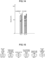
FIG. 14 is a graph illustrating the heat balance in the furnace per unit time values before and after increasing the coke ratio. -
FIG. 15 is a diagram illustrating an example of an input interface that can designate arbitrary values of a plurality of operation variables. -
FIG. 16 is a graph illustrating the material balance in the furnace per unit time, values before and after increasing the coke ratio, and values after decreasing a pulverized coal flow rate. -
FIG. 17 is a graph illustrating the heat balance in the furnace per unit time, values before and after increasing the coke ratio, and values after decreasing the pulverized coal flow rate. -
FIG. 18 is a graph illustrating the material balance in the furnace per unit weight of hot metal, values before and after increasing the coke ratio, and values after decreasing the pulverized coal flow rate. -
FIG. 19 is a graph illustrating the heat balance in the furnace per unit time, values before and after increasing the coke ratio, and values after decreasing the pulverized coal flow rate. - An operation guidance method, a blast furnace operation method, a hot metal manufacturing method, and an operation guidance apparatus according to an embodiment of the present invention will be described with reference to the drawings.
- A configuration of an operation guidance apparatus according to the embodiment of the present invention will be described with reference to
FIG. 1 . Anoperation guidance apparatus 100 includes aninformation processing device 101, aninput device 102, and anoutput device 103. - The
information processing device 101 is configured with a general-purpose device such as a personal computer or a workstation, and includes aRAM 111, aROM 112, and aCPU 113. TheRAM 111 temporarily stores a processing program and processing data related to processing executed by theCPU 113 and functions as a working area of theCPU 113. - The
ROM 112 stores acontrol program 112a for executing the operation guidance method according to the embodiment of the present invention, and the processing program and the processing data for controlling the entire operation of theinformation processing device 101. - The
CPU 113 controls the entire operation of theinformation processing device 101 according to thecontrol program 112a and the processing program stored in theROM 112. TheCPU 113 functions as a first prediction unit that performs a first prediction step, a second prediction unit that performs a second prediction step, and a display unit that performs a display step in the operation guidance method to be described later. - The
input device 102 includes devices such as a keyboard, a mouse pointer, and a numeric keypad, and is operated to input various types of information to theinformation processing device 101. Theoutput device 103 includes a display device, a printing device, and the like, and outputs various types of processed information of theinformation processing device 101. Theoutput device 103 displays an oxygen balance in a raceway region, a carbon balance in an entire furnace, an oxygen balance derived from iron oxide in the entire furnace, a heat balance in the furnace, and the like in the operation guidance method to be described later. The "raceway region" refers to a region at about 2000°C where coke in the furnace is burned by oxygen in hot air blown from a tuyere. - Next, a physical model used in the operation guidance method according to the embodiment of the present invention will be described. Similarly to a method described in Reference Literature 1 (Michiharu Hatano et al., "Investigation of Blow-in Operation through the Blast Furnace Dynamic Model ", Iron and Steel, vol. 68, p. 2369), the physical model used in the present invention includes a partial differential equation group considering a plurality of physical phenomena such as reduction of iron ore, heat exchange between iron ore and coke, and melting of iron ore. In addition, the physical model used in the present invention is a physical model capable of calculating a variable (output variable) indicating a state in the blast furnace in a non-steady state (hereinafter referred to as a "dynamic model").
- As illustrated in
FIG. 2 , major time-varying conditions (input variables, blast furnace operation variables (also referred to as operational factors)) among boundary conditions given to the dynamic model are as follows. - (1) Coke ratio (CR) at furnace top [kg/t]: Coke input per ton of hot metal
- (2) Blast air flow rate (BV) [Nm3/min]: Flow rate of air supplied to the blast furnace
- (3) Enriched oxygen flow rate (BVO) [Nm3/min]: Flow rate of enriched oxygen blown into the blast furnace
- (4) Blast temperature (BT) [°C]: Temperature of air and enriched oxygen supplied to the blast furnace
- (5) Pulverized coal flow rate (pulverized coal blowing rate, PCI) [kg/min]: Weight of pulverized coal used for one ton of hot metal production
- (6) Blast air moisture (BM) [g/Nm3]: Moisture of air supplied to the blast furnace
- In addition, major output variables formed by the dynamic model are as follows.
- (1) Gas utilization ratio in the furnace (ηCO): CO2/(CO + CO2)
- (2) Temperature of coke and iron
- (3) Oxidation degree of iron ore
- (4) Descent rate of raw material
- (5) Solution-loss carbon amount (sol. loss carbon amount)
- (6) Hot metal temperature
- (7) Hot metal making rate (hot metal production speed)
- (8) Furnace body heat loss amount: Amount of heat deprived by cooling water when the furnace body is cooled by cooling water
- In the present invention, a time step (time interval) for calculating the output variables is 30 minutes. However, the time step can be changed according to the purpose, and is not limited to the value of the present embodiment.
- The dynamic model described above can be expressed, for example, by the following formulas (1) and (2). By using this dynamic model, it is possible to calculate the output variables including momentarily changing hot metal temperature and hot metal making rate.


- Here, in the above formulas (1) and (2), x(t) is a state variable (temperature of coke or iron, oxidation degree of iron ore, descent rate of raw material, and the like) calculated in the dynamic model, and y(t) is a control variable such as a hot metal temperature (HMT) and the hot metal making rate. In addition, C is a matrix or a function for extracting the control variable from state variables calculated in the dynamic model.
- In addition, u(t) in the above formula (1) is an input variable in the dynamic model such as the blast air flow rate, the enriched oxygen flow rate, the pulverized coal flow rate, the blast air moisture, the blast temperature, and the coke ratio. This u(t) can be expressed by "u(t) = (BV(t), BVO(t), PCI(t), BM(t), BT(t), or CR(t))".
- Next, the operation guidance method according to the present embodiment will be described. The operation guidance method according to the present embodiment performs the first prediction step, the second prediction step, a balance calculation step, and the display step. Either the first prediction step or the second prediction step may be performed first. In addition, both the first prediction step and the second prediction step are not necessarily performed, and either one may be performed.
- In the first prediction step, the dynamic model described above is used to predict a state in the blast furnace at an arbitrary future time when the current operation state is retained in the future. Examples of the state in the blast furnace predicted in this step are the hot metal temperature, the hot metal making rate, air permeability of the blast furnace, and a pressure loss indicating a difference between the pressure at the furnace top and the pressure at the tuyere. In the present embodiment, a case where the hot metal temperature and the hot metal making rate are predicted in this step will be described. A specific example of the first prediction step will be described later.
- In the second prediction step, the dynamic model described above is used to predict a future state inside the blast furnace when the operation is performed under arbitrary virtual operating conditions input by the operator. In this step, for example, the
output device 103 displays an input interface (FIG. 15 ) that can designate arbitrary values of a plurality of operation variables indicating the operating conditions, and the state in the blast furnace at an arbitrary future time is predicted based on the values of the operation variables designated by the operator. In the present embodiment, a case where the hot metal temperature and the hot metal making rate are predicted in this step will be described. A specific example of the second prediction step will be described later. - In the balance calculation step, a material balance and a heat balance in the furnace are calculated. The material balance in the furnace includes the oxygen balance in the raceway region, the carbon balance in the entire furnace, and the oxygen balance derived from iron oxide in the entire furnace.
- The oxygen balance in the raceway region indicates a relationship between a supply speed of oxygen blown into the raceway region and a consumption speed of carbon burned in the raceway region (
FIG. 3 to be described later). In addition, the carbon balance in the entire furnace indicates a relationship between a supply speed of carbon derived from coke supplied from the furnace top and the consumption speed of carbon burned in the furnace (FIG. 4 to be described later). - In addition, the oxygen balance derived from iron oxide indicates a relationship among a charging speed of iron derived from iron oxide supplied from the furnace top, a charging speed of oxygen derived from iron oxide supplied from the furnace top, and a reduction reaction speed of iron oxide supplied from the furnace top by gas (
FIG. 5 to be described later). The heat balance in the furnace indicates a relationship between a heat input into the furnace and a heat consumed in the furnace (FIG. 7 to be described later). - Specifically, this step calculates the current material balance and heat balance, the material balance and the heat balance at the arbitrary future time when the state in the blast furnace is predicted in the first prediction step, and the material balance and the heat balance at the arbitrary time when the state in the blast furnace is predicted in the second prediction step. Note that details of each balance calculated in the balance calculation step will be described later (
FIGS. 3 to 9 ,FIGS. 11 to 14 , andFIGS. 15 to 19 to be described later). - In the display step, each balance calculated in the balance calculation step is displayed on the
output device 103 and presented to the operator. In this step, theoutput device 103 displays the current material balance and the heat balance, the material balance and the heat balance at the arbitrary future time when the state in the blast furnace is predicted in the first prediction step, and the material balance and the heat balance at any future time when the state in the blast furnace is predicted in the second prediction step. Note that details of each balance calculated to display in the display step will be described later (FIGS. 11 to 14 andFIGS. 16 to 19 described later). - When the first prediction step is performed, the oxygen balance in the raceway region, the carbon balance in the entire furnace, and the oxygen balance derived from iron oxide in the entire furnace are displayed in this step as follows. In other words, with respect to these balances, the current state and a state when the current operation state is retained in the future are displayed side by side in a comparable manner along a same axis direction in one graph in this step (
FIGS. 11 and13 ). As a result, it is possible to visually present to the operator the material balance in the furnace when the current operation state is retained in the future, so that the operator can be easily guided to take an appropriate operational action. - In addition, when the second prediction step is performed in addition to the first prediction step, the oxygen balance in the raceway region, the carbon balance in the entire furnace, and the oxygen balance derived from iron oxide in the entire furnace are displayed in this step as follows. In other words, with respect to these balances, the current state and the state when the current operation state is retained in the future or the state when the operation is performed under the virtual operating conditions are displayed side by side in a graph in a comparable manner along the same axis direction in this step (
FIGS. 16 and18 ). As a result, the material balance in the furnace when the operation is performed under the virtual operating conditions can be visually presented to the operator, so that the operator can be easily guided to take an appropriate operational action. - In addition, in this step, the oxygen balance in the raceway region, the carbon balance in the entire furnace, and the oxygen balance derived from iron oxide in the entire furnace are displayed side by side in a first axis direction on the graph, except for the charging speed of iron derived from iron oxide. Then, the charging speed of iron derived from iron oxide is displayed in a second axis direction orthogonal to the first axis direction (
FIGS. 11 ,13 ,16 , and18 ). In other words, when there are values proportional to each other among balance values, these values are arranged and presented on different axes instead of the same axis. As a result, it is possible to present the relationship between the balance values to the operator, so that the operator can be easily guided to take an appropriate operational action. - Still more, in this step, the following information may be displayed in addition to the oxygen balance in the raceway region, the carbon balance in the entire furnace, and the oxygen balance derived from iron oxide. In other words, in addition to these balances, the heat balance in the furnace indicating a relationship between the heat input into the furnace and the heat consumed in the furnace may be displayed on the output device 103 (
FIGS. 12 ,14 ,17 , and19 ) and presented to the operator in this step. This makes it possible to visually present the heat balance in the furnace to the operator. Accordingly, the operator can be easily guided to take an appropriate operational action. - Still more, in this step, the oxygen balance in the raceway region, the carbon balance in the entire furnace, the oxygen balance derived from iron oxide, and the heat balance in the furnace may be displayed per unit time (
FIGS. 11 ,12 ,16 , and17 ). Alternatively, in this step, each balance may be converted and displayed per unit weight of hot metal (FIGS. 14, 15 ,18 , and19 ). As described above, by converting and indicating the material balance and the heat balance in the furnace per unit weight of hot metal, an amount of pulverized coal, an amount of coke, an amount of solution loss carbon, and a sensible heat of hot metal and slag per unit weight of hot metal can be presented to the operator. - Furthermore, in this step, changes before and after the prediction of operation indexes, including the hot metal making rate, the coke ratio, and the pulverized coal flow ratio, of the operation state predicted in at least one of the first prediction step and the second prediction step are displayed in a comparable manner (
FIGS. 11 ,13 ,16 , and18 ). As a result, changes before and after the prediction of the operation state and an operation index can be visually presented to the operator, so that the operator can be easily guided to take an appropriate operational action. - Hereinafter, details of each balance calculated in the balance calculation step and displayed in the display step will be described.
- First, the oxygen balance in the raceway region will be described. Oxygen blown into the raceway region includes blast air (including enriched oxygen), blast air moisture, and oxygen in pulverized coal. Respective supply (charging) speeds [kmolO/sec] are defined as O_in(1), O_in(2), and O_in(3). Carbon burned in the raceway region is derived from coke or pulverized coal. Therefore, reaction between oxygen and carbon in the raceway region is represented by one of the following formulas (3) to (6).
C (coke) + 1/2O 2 = CO (3)
C (coke) + H 2 O = CO + H2 (4)
C (coal) + 1/2O 2 = CO (5)
C (coal) + O (coal) = CO (6)
- Here, a carbon consumption speed according to the above formula (3) is defined as C_out(1), a carbon consumption speed according to the above formula (4) is defined as C_out(2), and carbon consumption speed according to the above formulas (5) and (6) are defined as C_out(3). In any of reaction forms of the above formulas (3) to (6), the supply speed of oxygen [kmolO/sec] blown into the raceway region has to coincide with the consumption speed of carbon [kmolC/sec] as represented by the following formula (7) because a molar ratio of C to O is 1: 1.

-
FIG. 3 is a bar graph illustrating a balance relationship expressed by the above formula (7). - Next, the carbon balance in the coke in the entire furnace will be described. In addition to the carbon consumed according to the above formulas (3) and (4) in the raceway region, carbon is consumed by reactions represented by the following formulas (8) to (12) in the furnace.

C + CO 2 = 2CO (9)
C + H 2 O = CO + H 2 (10)
FeO + C = Fe + CO (11)
(SiO 2) + 2C = [Si] + 2CO (12)
- Here, a carbon consumption speed according to the above formula (8) is defined as C_out(4), and carbon consumption speed according to the above formulas (9) to (12) are defined as C_out(5). In addition, when the supply speed of carbon derived from coke supplied from the furnace top (hereinafter referred to as "supply speed of carbon supplied from furnace top") is C_top_in, the carbon consumption speed is equal to the carbon supply speed in the steady state, and the following formula (13) is established.

- However, it is necessary to note that the above formula (13) is not established in a transient state such as immediately after changing the coke ratio.
FIG. 4 is a bar graph illustrating a balance relationship between the carbon supply speed and the carbon consumption speed indicated by the above formula (13). - In addition, the following relationship is established between C_top_in that is the supply speed of carbon supplied from the furnace top and Fe_top_in that is a supply speed of Fe derived from iron oxide in the ore (hereinafter referred to as "supply speed of Fe in ore"). In other words, a proportional relationship represented by the following Formula (14) is established between C_top_in and Fe_top_in by using a coke ratio CR [kg/t] that is the operation variable of the operator.

- Next, the oxygen balance derived from iron oxide will be described. Oxygen derived from iron oxide in the ore is reduced by any one of reactions represented by the following formulas (15) to (17).
FeO + C = Fe + CO (15)
FeOx + CO = FeO x-1 + CO 2 (16)
FeOx + H 2 O = FeO x-1 + H 2 O (17)
- On the other hand, reactions represented by the above formulas (9) and (10) also occur to restore CO2 and H2O generated by the reactions represented by the above formulas (15) to (17) to CO and H2 gases.
- Here, a value obtained by subtracting a reaction speed O_red(1) of direct reduction represented by the sum of the above formulas (9), (10), and (15) from a reduction speed O_red(0) of iron oxide in the ore represented by the sum of the above formulas (15) to (17) is set as a gas reduction reaction speed O_red(2) = O_red(0) - O_red(1). In addition, when the supply speed of oxygen derived from iron oxide in the ore (hereinafter referred to as "supply speed of oxygen in ore") supplied from the furnace top is indicated as O_top_in, the oxygen balance as represented by the following formula (18) is established in the steady state.

- Further, a proportional relationship as represented by the following formula (19) is established between Fe_top_in that is the supply speed of Fe in ore and O_top_in that is the supply speed of oxygen in ore described above when an ore oxidation degree a (approximately 1.5) at the furnace top is used.

-
FIG. 5 is a bar graph illustrating the supply speed of oxygen in the ore, the supply speed of Fe in the ore, and the gas reduction reaction speed.FIG. 6 is obtained by integrating the oxygen balance in the raceway region, the carbon balance derived from coke in the entire furnace, and the oxygen balance derived from iron oxide in the entire furnace illustrated inFIGS. 3 to 5 .FIG. 6 illustrates a value of the material balance in the furnace per unit time. In addition, in a vertical axis ofFIG. 6 , a positive side indicates an increase of value in the furnace, and a negative side indicates a decrease of value in the tuyere. In addition, as illustrated inFIG. 6 a line segment connecting respective balance values (e.g., a line segment OG, a line segment AF, and a line segment BE) may be clearly indicated, or a meaning of an inclination of a line segment BE, which is the pulverized coal ratio PCR, may be clearly indicated in the graph. As described above, by clearly indicating the operation variable associated with the value of each balance in the graph, it is possible to visually present, for example, a factor causing a change in the hot metal making rate and the hot metal temperature to the operator. - An inclination of a line segment AF in
FIG. 6 is proportional to the coke ratio CR expressed by the above formula (14). An inclination of the line segment BE means the amount of carbon in the pulverized coal per charged iron mole, and is proportional to the pulverized coal ratio. In addition, an inclination of the line segment OG is a in the above formula (19), which means a proportional constant of Fe_top_in that is the supply speed of Fe in the ore and O_top_in that is the supply speed of oxygen in the ore. - By presenting the current material balance and the material balance when the operator changes the operation variable using an integrated graph of the material balance in the furnace, it is possible to quantitatively grasp the change in the hot metal making rate [t/min] when the operator changes the operation variable (
FIGS. 16 and18 ). - For example, when only the pulverized coal flow rate is increased while retaining other operation variables, a line segment AB becomes long while a length of a line segment OB remains unchanged, so that the carbon consumption speed in the raceway region represented by a length of a line segment OA decreases. Therefore, a line segment CA corresponding to the supply speed of carbon supplied from the furnace top (C_top_in) is also shortened. As a result, a line segment CF corresponding to the supply speed of Fe in the ore supplied from the furnace top (Fe_top_in) is also shortened in proportion to the line segment CA, and thus the hot metal making rate decreases.
- Next, the heat balance in the furnace will be described. Heat input into the furnace is derived from combustion heat of coke and pulverized coal at the tuyere, indirect reduction heat in the furnace, and blast sensible heat. These are defined as Q_in(1), Q_in(2), and Q_in(3), respectively. The heat consumed in the furnace is classified into sensible heat of hot metal and slag, direct reduction reaction heat, gasification reaction heat of coke due to blast air moisture, heat loss released from the furnace wall to cooling water or the atmosphere, sensible heat of gas discharged from the furnace top, and the like. These are respectively defined as Q_out(1), Q_out(2), Q_out(3), Q_out(4), and Q_out(5).
- These are illustrated by bar graphs in
FIG. 7. FIG. 7 illustrates a value of the heat balance in the furnace per unit time. The heat balance in the furnace satisfies a relationship of the following formula (20) in the steady state.

- Here, the material balance and the heat balance in the furnace illustrated in
FIGS. 6 and7 are values per unit time On the other hand, in order to obtain a hot metal temperature substantially proportional to the hot metal sensible heat per unit weight of hot metal, a reduction material ratio that is an amount of carbon material per unit weight of hot metal, and the like, it is necessary to obtain the material balance and the heat balance per unit weight of hot metal. Therefore, values obtained by dividing the variables illustrated inFIGS. 6 and7 by Fe_top_in (the supply speed of Fe in the ore supplied from the furnace top) are illustrated inFIGS. 8 and9 . As described above, by converting and indicating the material balance and the heat balance in the furnace per unit weight of hot metal, an amount of pulverized coal, an amount of coke, an amount of solution loss carbon, and a sensible heat of hot metal and slag per unit weight of hot metal can be presented to the operator. - [Specific example of first prediction step]
- Hereinafter, a specific example of the first prediction step of the operation guidance method will be described. First, on the assumption that the operation amounts of all the current operation variables are kept constant, prediction calculation of the future hot metal temperature and the future hot metal making rate is performed. Specifically, the current time step is set to t = 0, and the future hot metal temperature and the future hot metal making rate are calculated using the following Formulas (21) and (22).


- A response y0 of the control variable (here, the hot metal temperature and the hot metal making rate) obtained in this manner is referred to as a "free response" in the present embodiment. The free response of the hot metal making rate and the hot metal temperature when the operational action of increasing the coke ratio was carried out two hours before is indicated by solid lines in
FIGS. 10(c) and 10(d) . As illustrated in the graphs, by increasing the coke ratio, the hot metal making rate decreases by about 1000 t/day, and the hot metal temperature increases by about 100°C. - In addition, in
FIGS. 11 and12 , bar graphs of the material balance and the heat balance in the furnace state predicted in the first prediction step are arranged next to the bar graphs of the material balance and the heat balance in the furnace illustrated inFIGS. 8 and9 . - In
FIGS. 11 and12 , the left side indicates a value immediately before increasing the coke ratio (current state) in each of the bar graphs indicating O_in, C_out, C_top_in, C_out, O_top_in, O_red, Q_in, and Q_out. The right side of each bar graph indicates a value after 12 hours from the increase of the coke ratio. Also inFIG. 11 , an upper graph is a value immediately before (current state) increasing the coke ratio, and a lower graph is a value 12 hours after increasing the coke ratio in bar graphs indicating Fe_top_in. - In
FIG. 11 , a reason that a length of a line segment AE representing the hot metal making rate is decreased is that the inclination of the line segment AF proportional to the coke ratio has increased and a length of the line segment CA corresponding to the supply speed of carbon supplied from the furnace top (C_top_in) has shortened. In addition, the increase in the inclination of the line segment AF is a direct effect of increasing the coke ratio. As a result, the line segment AE corresponding to the hot metal making rate is shortened. In addition, since the supply speed (O_top_in) of oxygen in the ore supplied from the furnace top decreases in proportion thereto, the consumption speed of carbon by direct reduction also decreases. Furthermore, since a carburizing speed substantially proportional to the hot metal making rate also decreases, a length of a line segment CO also decreases. Therefore, the line segment CA corresponding to the carbon supply speed (C_top_in) from the furnace top is shortened, and the hot metal making rate further decreases. - In addition, as illustrated in
FIG. 12 , it is apparent that there is no change in the total amount and breakdown of the amount of heat per unit time supplied to the furnace, but heat loss and gas sensible heat at the furnace top increase while the sensible heat of hot metal and slag decreases. - In addition,
FIGS. 13 and14 illustrate results of converting the material balance and the heat balance in the furnace per unit time, illustrated inFIGS. 11 and12 , into those per unit weight of hot metal. As illustrated inFIG. 13 , a line segment connecting respective balance values (e.g., a line segment O'G', a line segment A'F', and a line segment B'E') may be clearly indicated, or a meaning of the line segment A'B', which is the pulverized coal ratio PCR, may be clearly indicated in the graph. - As illustrated in
FIG. 13 , it is apparent that the line segment O'A' becomes longer after increasing the coke ratio. This means that since the coke ratio was increased, the amount of coke per unit weight of hot metal at a tuyere height has increased after undergoing direct reduction and carburization reaction in the furnace. In addition, the line segment A'B' indicating the pulverized coal ratio is also extended. This is because, similar toFIG. 11 , the pulverized coal amount per unit weight of hot metal has increased due to a decrease in the hot metal making rate while the pulverized coal flow rate remains unchanged. - Further, as illustrated in
FIG. 14 , since the hot metal making rate decreases, an amount of heat supplied per unit weight of hot metal increases both in blast sensible heat and in carbon combustion heat at the tuyere. In addition, it is apparent that the hot metal temperature increases since the amount per unit weight of hot metal also increases with respect to the sensible heat of hot metal and slag per unit time that has decreased inFIG. 12 . As described above, by presenting the material balance and the heat balance per unit time and per unit weight of hot metal in the graphs, it is possible for the operator to consider a cause of change in the hot metal making rate and the hot metal temperature. - Hereinafter, a specific example of the second prediction step will be described. By performing the first prediction step described above and presenting the material balance and the heat balance in the furnace based on the results, it is possible to foresee future changes in the in-furnace state and control variables. However, it is necessary for the operator to take an appropriate operational action in response to the changes. For example, in
FIG. 10 , it is predicted that the hot metal temperature will rise to near 1600°C, which is excessive. Therefore, by performing the second prediction step, the future material balance and heat balance in the furnace when the operator virtually changes the operation variable can also be presented. - The operation variables (virtual operation variables) that can be operated by the operator are, as described above, the blast air flow rate, the enriched oxygen flow rate, the pulverized coal flow rate, the coke ratio, the blast air moisture, and the blast temperature. Therefore, for example, as illustrated in
FIG. 15 , the input interface capable of designating an arbitrary value of each operation variable is displayed on theoutput device 103, and the future state in the blast furnace is predicted based on the operation variable designated by the input interface. Specifically, an operation variable u1 is designated by the input interface, and future prediction under the virtual operating condition is performed, for example, by the following formulas (23) and (24).


- For example, as illustrated in
FIG. 10 described above, it is considered that the pulverized coal flow rate is decreased to keep the hot metal temperature in an appropriate range at the timing two hours after the coke ratio is increased. Here, the operator manipulates the value of the pulverized coal flow rate PCI inFIG. 15 to decrease the pulverized coal flow rate by 150 kg/min, and the results (response y1) of predicting the hot metal making rate and the hot metal temperature by the above Formulas (23) and (24) are indicated by broken lines inFIGS. 10(c) and 10(d) . As illustrated in the graphs, it is apparent that when the operator performs the operation to decrease the pulverized coal flow rate, the hot metal temperature, which was excessive due to the increase in the coke ratio, can be returned to an appropriate level. - In addition, with respect to the bar graphs illustrated in
FIGS. 11 and12 , the bar graphs of the material balance and the heat material balance in the in-furnace state predicted in the first prediction step are replaced with bar graphs of the material balance and the heat balance in the in-furnace state predicted in the second prediction step. These bar graphs are illustrated inFIGS. 16 to 19 .FIG. 16 is a graph illustrating the material balance in the furnace per unit time,FIG. 17 is a graph illustrating the heat balance in the furnace per unit time,FIG. 18 is a graph illustrating the material balance in the furnace per unit weight of hot metal, andFIG. 19 is a graph illustrating the heat balance in the blast furnace per unit time. - In
FIGS. 16 to 19 , the left side of each of graphs indicating O_in, C_out, C_top_in, C_out, O_top_in, O_ red, Q_in, and Q_out is a value immediately before increasing the coke ratio (current state). The right side of each of the graphs is a value after the virtual operational action is performed. In the same graphs, an upper graph is a value immediately before (current state) increasing the coke ratio, and a lower graph is a value after performing the virtual operational action in the bar graphs indicating Fe_top_in. - When
FIG. 11 andFIG. 16 are compared, it is apparent that the supply speed (C_top_in) of carbon supplied from the furnace top is increased by decreasing the pulverized coal flow rate and increasing the carbon consumption speed at the tuyere. As a result, the hot metal making rate decreased due to the increase in the coke ratio can be recovered to a level before the increase in the coke ratio. - In addition, since the hot metal making rate increases and the pulverized coal flow rate decreases, the inclination of the line segment BE in
FIG. 16 representing the pulverized coal ratio and a length of a line segment A'B' inFIG. 18 decrease, and thus, an increase in sensible heat of hot metal and slag due to the increase in the coke ratio is compensated. As a result, as indicated by a broken line inFIG. 10(d) , the hot metal temperature can be maintained at a value substantially equivalent to the level before the increase in the coke ratio. - In addition,
FIGS. 16 to 19 exemplify a most typical operational action of decreasing the pulverized coal flow rate with respect to a decrease in the hot metal making rate and an increase in the hot metal temperature due to the increase in the coke ratio. In addition, for example, it is possible to achieve a similar control purpose by increasing the blast air flow rate or the oxygen flow rate. A solution of a combined action by operation variables is also conceivable. - The operation guidance method according to the present embodiment can also be applied to an operation method of the blast furnace. In this case, in addition to the first prediction step, the second prediction step, the balance calculation step and the display step in the operation guidance method described above, a step of controlling the blast furnace according to the guidance in the display step is included.
- The operation guidance method according to the present embodiment can also be applied to a hot metal manufacturing method. In this case, in addition to the first prediction step, the second prediction step, the balance calculation step, and the display step in the operation guidance method described above, a step of manufacturing hot metal by controlling the blast furnace according to the guidance in the display step is performed.
- According to the operation guidance method, the blast furnace operation method, the hot metal manufacturing method, and the operation guidance apparatus according to the present embodiment as described above, the oxygen balance in the raceway region, the carbon balance in the entire furnace, and the oxygen balance derived from iron oxide in the entire furnace when the state in the blast furnace is predicted are displayed. As a result, the operator is guided to take an appropriate operational action. Therefore, a highly efficient and stable operation of the blast furnace can be realized.
- In addition, according to the operation guidance method, the blast furnace operation method, the hot metal manufacturing method, and the operation guidance apparatus according to the present embodiment, the prediction result of the in-furnace state under the virtual operating conditions designated by the operator or the future prediction result without any operation can be presented together with the material balance and the heat balance. As a result, the operator can quantitatively and reasonably grasp the effect of the operational action and reach an appropriate operational action by himself/herself.
- Although the operation guidance method, the blast furnace operation method, the hot metal manufacturing method, and the operation guidance apparatus according to the present invention have been specifically described with reference to the embodiments and examples for carrying out the invention, the gist of the present invention is not limited to these descriptions and has to be broadly interpreted based on the description of the claims. It is obvious that various changes and modifications based on the descriptions are also included in the gist of the present invention.
-
- 100
- OPERATION GUIDANCE APPARATUS
- 101
- INFORMATION PROCESSING DEVICE
- 102
- INPUT DEVICE
- 103
- OUTPUT DEVICE
- 111
- RAM
- 112
- ROM
- 112a
- CONTROL PROGRAM
- 113
- CPU
Claims (11)
- An operation guidance method comprising:a first prediction step of predicting a state in a blast furnace when a current operation state is retained in a future, by using a physical model that is able to calculate the state in the blast furnace; anda display step of displaying, on an output device, an oxygen balance in a raceway region, a carbon balance in an entire furnace, and an oxygen balance derived from iron oxide in the entire furnace, when the state in the blast furnace is predicted.
- The operation guidance method according to claim 1, wherein in the display step, a current state and a state when the current operation state is retained in the future are displayed side by side in a comparable manner with respect to the oxygen balance in the raceway region, the carbon balance in the entire furnace, and the oxygen balance derived from iron oxide in the entire furnace.
- The operation guidance method according to claim 2 further comprisinga second prediction step of predicting, by using the physical model, a future state in the blast furnace when an operation is performed under an arbitrary virtual operating condition which is input by an operator, whereinin the display step, the current state and a state when the operation is performed under the virtual operating condition are displayed side by side in a comparable manner on a graph with respect to the oxygen balance in the raceway region, the carbon balance in the entire furnace, and the oxygen balance derived from iron oxide in the entire furnace.
- The operation guidance method according to claim 3, wherein in the second prediction step,the output device displays an input interface that is able to designate an arbitrary value of a plurality of operation variables indicating the operating condition, andthe future state in the blast furnace is predicted based on the plurality of operation variables designated by the input interface.
- The operation guidance method according to any one of claims 2 to 4, whereinthe oxygen balance in the raceway region indicates a relationship between a supply speed of oxygen blown into the raceway region and a consumption speed of carbon burned in the raceway region,the carbon balance in the entire furnace indicates a relationship between a supply speed of carbon derived from coke supplied from a furnace top and a consumption speed of carbon burned in a furnace,the oxygen balance derived from iron oxide in the entire furnace indicates a relationship among a charging speed of iron derived from iron oxide supplied from the furnace top, a charging speed of oxygen derived from iron oxide supplied from the furnace top, and a reduction reaction speed of iron oxide, by gas, supplied from the furnace top, andin the display step,the oxygen balance in the raceway region, the carbon balance in the entire furnace, and the oxygen balance derived from iron oxide in the entire furnace, except for the charging speed of iron derived from iron oxide, are displayed side by side in a first axis direction on the graph, andthe charging speed of iron derived from iron oxide is displayed in a second axis direction orthogonal to the first axis direction.
- The operation guidance method according to claim 3 or 4, wherein in the display step, a change before and after prediction of an operation index, predicted in at least one of the first prediction step and the second prediction step, is displayed in a comparable manner, where the operation index includes an operation state of: a hot metal making rate; a coke ratio; and a pulverized coal flow ratio.
- The operation guidance method according to any one of claims 1 to 6, wherein the display step includes displaying a heat balance in the furnace indicating a relationship between heat input into the furnace and heat consumed in the furnace, in addition to the oxygen balance in the raceway region, the carbon balance in the entire furnace, and the oxygen balance derived from iron oxide in the entire furnace.
- The operation guidance method according to any one of claims 1 to 7, wherein the display step displays each balance by converting each balance in terms of a value per unit weight of hot metal.
- A blast furnace operation method comprising a step of controlling a blast furnace based on guidance according to the operation guidance method according to any one of claims 1 to 8.
- A hot metal manufacturing method comprising a step of manufacturing hot metal by controlling a blast furnace based on guidance according to the operation guidance method according to any one of claims 1 to 8.
- An operation guidance apparatus comprising:a prediction unit configured to predict a state in a blast furnace when a current operation state is retained in a future, by using a physical model that is able to calculate the state in the blast furnace; anda display unit configured to display an oxygen balance in a raceway region, a carbon balance in an entire furnace, and an oxygen balance derived from iron oxide in the entire furnace, when the state in the blast furnace is predicted.
Applications Claiming Priority (2)
| Application Number | Priority Date | Filing Date | Title |
|---|---|---|---|
| JP2020116370A JP7272326B2 (en) | 2020-07-06 | 2020-07-06 | Operation Guidance Method, Blast Furnace Operation Method, Hot Metal Production Method, Operation Guidance Device |
| PCT/JP2021/022619 WO2022009621A1 (en) | 2020-07-06 | 2021-06-15 | Operation guidance method, method for operating blast furnace, method for manufacturing molten iron, operation guidance device |
Publications (3)
| Publication Number | Publication Date |
|---|---|
| EP4177359A1 true EP4177359A1 (en) | 2023-05-10 |
| EP4177359A4 EP4177359A4 (en) | 2023-11-15 |
| EP4177359B1 EP4177359B1 (en) | 2025-09-03 |
Family
ID=79552928
Family Applications (1)
| Application Number | Title | Priority Date | Filing Date |
|---|---|---|---|
| EP21838845.2A Active EP4177359B1 (en) | 2020-07-06 | 2021-06-15 | Operation guidance method, blast furnace operation method, hot metal manufacturing method, and operation guidance apparatus |
Country Status (7)
| Country | Link |
|---|---|
| US (1) | US20230313329A1 (en) |
| EP (1) | EP4177359B1 (en) |
| JP (1) | JP7272326B2 (en) |
| KR (1) | KR102933531B1 (en) |
| CN (1) | CN115735010B (en) |
| TW (1) | TWI788892B (en) |
| WO (1) | WO2022009621A1 (en) |
Families Citing this family (9)
| Publication number | Priority date | Publication date | Assignee | Title |
|---|---|---|---|---|
| JP7602132B2 (en) * | 2021-03-24 | 2024-12-18 | 日本製鉄株式会社 | Blast furnace operation method |
| WO2024048214A1 (en) * | 2022-08-31 | 2024-03-07 | Jfeスチール株式会社 | Process control method, blast furnace operation method, molten pig iron production method, and process control apparatus |
| JP7679812B2 (en) * | 2022-08-31 | 2025-05-20 | Jfeスチール株式会社 | Process control method, blast furnace operation method, molten iron manufacturing method, and process control device |
| CN116027745B (en) * | 2022-12-15 | 2024-04-12 | 广东镭目华远智能科技有限公司 | A platform control method based on the operation time flow control of the molten iron tank |
| KR20250116093A (en) * | 2023-02-21 | 2025-07-31 | 제이에프이 스틸 가부시키가이샤 | Process control method, blast furnace operation method, molten iron manufacturing method, process control device and program |
| WO2024185626A1 (en) * | 2023-03-07 | 2024-09-12 | Jfeスチール株式会社 | Molten iron temperature control method, blast furnace operation method, molten iron production method, molten iron temperature control device, and molten iron temperature control system |
| JP7522999B1 (en) * | 2023-03-07 | 2024-07-26 | Jfeスチール株式会社 | Molten iron temperature control method, blast furnace operation method, molten iron manufacturing method, molten iron temperature control device, and molten iron temperature control system |
| WO2024204465A1 (en) * | 2023-03-30 | 2024-10-03 | Jfeスチール株式会社 | Molten iron temperature control method, molten iron temperature control device, molten iron temperature control system, and terminal device |
| KR20250142410A (en) * | 2023-03-30 | 2025-09-30 | 제이에프이 스틸 가부시키가이샤 | Melting point temperature control method, melting point temperature control device, melting point temperature control system and terminal device |
Family Cites Families (21)
| Publication number | Priority date | Publication date | Assignee | Title |
|---|---|---|---|---|
| JPS6018721B2 (en) * | 1978-02-27 | 1985-05-11 | 住友金属工業株式会社 | How to operate a blast furnace |
| JP2678767B2 (en) * | 1988-06-17 | 1997-11-17 | 川崎製鉄株式会社 | Blast furnace operation method |
| KR100381094B1 (en) | 1996-12-09 | 2003-07-22 | 주식회사 포스코 | Method for theoretic combustion temperature of race way during blast furnace pulverized coal injection operation |
| JPH11106807A (en) * | 1997-09-30 | 1999-04-20 | Sumitomo Metal Ind Ltd | Blast furnace charge distribution control support system |
| JPH11335710A (en) | 1998-05-22 | 1999-12-07 | Sumitomo Metal Ind Ltd | Blast furnace heat prediction method |
| JP3659826B2 (en) | 1998-12-24 | 2005-06-15 | コベルコクレーン株式会社 | Work management system for trencher type soil cement wall excavator |
| JP4976822B2 (en) * | 2006-11-14 | 2012-07-18 | 株式会社神戸製鋼所 | Production method and apparatus of granular metallic iron |
| JP5400555B2 (en) | 2009-03-31 | 2014-01-29 | 株式会社神戸製鋼所 | Blast furnace operating condition deriving method and blast furnace operating condition deriving apparatus using this method |
| JP5482802B2 (en) | 2010-01-14 | 2014-05-07 | 新日鐵住金株式会社 | Steel making method |
| CN102952910B (en) * | 2012-10-29 | 2014-05-07 | 北京科技大学 | Calculation method of energy utilization after addition of high-reactivity coke into blast furnace |
| JP5546675B1 (en) * | 2012-12-07 | 2014-07-09 | 新日鉄住金エンジニアリング株式会社 | Blast furnace operating method and hot metal manufacturing method |
| KR101701658B1 (en) * | 2013-01-18 | 2017-02-01 | 제이에프이 스틸 가부시키가이샤 | Method for pretreating molten iron |
| CN104593532B (en) * | 2015-01-19 | 2017-07-07 | 河北联合大学 | A kind of ironmaking system furnace charge optimization method |
| JP6311659B2 (en) * | 2015-06-22 | 2018-04-18 | Jfeスチール株式会社 | Method for estimating layer thickness distribution in blast furnace, method for operating blast furnace, and apparatus for estimating layer thickness distribution in blast furnace |
| JP6690081B2 (en) | 2016-07-14 | 2020-04-28 | 株式会社神戸製鋼所 | Operation status evaluation system |
| JP6531782B2 (en) * | 2016-08-02 | 2019-06-19 | Jfeスチール株式会社 | Hot metal temperature prediction method, hot metal temperature prediction device, blast furnace operation method, operation guidance device, hot metal temperature control method, and hot metal temperature control device |
| KR102167985B1 (en) * | 2018-08-22 | 2020-10-20 | 주식회사 포스코 | System and method for perdicting closure time of tap hole of blast furnace |
| JP6930507B2 (en) * | 2018-08-23 | 2021-09-01 | Jfeスチール株式会社 | Hot metal temperature prediction method, hot metal temperature prediction device, blast furnace operation method, operation guidance device, hot metal temperature control method, and hot metal temperature control device |
| JP7103155B2 (en) | 2018-10-22 | 2022-07-20 | 日本製鉄株式会社 | Blast furnace operation method |
| CN109918702A (en) * | 2019-01-03 | 2019-06-21 | 上海交通大学 | A collaborative multi-objective optimization method for blast furnace batching and operation |
| CN110322057B (en) * | 2019-06-20 | 2023-04-18 | 江阴兴澄特种钢铁有限公司 | Prediction system and prediction method for carbon component in tapping of 100t direct-current electric arc furnace |
-
2020
- 2020-07-06 JP JP2020116370A patent/JP7272326B2/en active Active
-
2021
- 2021-06-15 WO PCT/JP2021/022619 patent/WO2022009621A1/en not_active Ceased
- 2021-06-15 CN CN202180047086.1A patent/CN115735010B/en active Active
- 2021-06-15 US US18/011,732 patent/US20230313329A1/en active Pending
- 2021-06-15 KR KR1020227046242A patent/KR102933531B1/en active Active
- 2021-06-15 EP EP21838845.2A patent/EP4177359B1/en active Active
- 2021-06-28 TW TW110123518A patent/TWI788892B/en active
Also Published As
| Publication number | Publication date |
|---|---|
| EP4177359A4 (en) | 2023-11-15 |
| JP2022014169A (en) | 2022-01-19 |
| KR102933531B1 (en) | 2026-03-03 |
| TW202212576A (en) | 2022-04-01 |
| US20230313329A1 (en) | 2023-10-05 |
| KR20230019154A (en) | 2023-02-07 |
| CN115735010A (en) | 2023-03-03 |
| BR112022026282A2 (en) | 2023-01-17 |
| TWI788892B (en) | 2023-01-01 |
| WO2022009621A1 (en) | 2022-01-13 |
| JP7272326B2 (en) | 2023-05-12 |
| EP4177359B1 (en) | 2025-09-03 |
| CN115735010B (en) | 2024-11-19 |
Similar Documents
| Publication | Publication Date | Title |
|---|---|---|
| EP4177359B1 (en) | Operation guidance method, blast furnace operation method, hot metal manufacturing method, and operation guidance apparatus | |
| EP4155421B1 (en) | Methods and devices for controlling hot metal temperature and operating a blast furnace | |
| EP3989013B1 (en) | Method for controlling process, operation guidance method, method for operating blast furnace, method for producing hot metal, and device for controlling process | |
| JP2012136767A (en) | Method for estimating phosphorus concentration in converter | |
| JP7067533B2 (en) | Si concentration prediction method for hot metal, operation guidance method, blast furnace operation method, molten steel manufacturing method and Si concentration prediction device for hot metal | |
| Halim | Effective utilization of using natural gas injection in the production of pig iron | |
| BR112022026282B1 (en) | METHOD FOR OPERATION GUIDANCE, METHOD FOR BLAST FURNACE OPERATION, METHOD FOR MANUFACTURING CAST METAL, AND OPERATION GUIDANCE APPARATUS | |
| Korpi et al. | Plant-wide optimization of a copper smelter: How to do it in practice | |
| JP7319538B2 (en) | Converter blowing control device, converter blowing control method and program | |
| EP4632081A1 (en) | Silicon concentration prediction method, operation guidance method, silicon concentration prediction device, operation guidance device, operation guidance system, and terminal device | |
| RU2825340C1 (en) | Method of determining amount of supplied heat, device for determining amount of supplied heat and method of operating blast furnace | |
| JP7384150B2 (en) | Operation guidance method, blast furnace operation method, hot metal production method and operation guidance device | |
| JP4484717B2 (en) | How to operate steelmaking equipment | |
| JP2025183922A (en) | Ironmaking speed control method, operation guidance method, molten iron production method, ironmaking speed control device, ironmaking speed control program, terminal device, and ironmaking speed control system | |
| Ferreira et al. | Predictions at the blow end of the LD-KGC converter by a semi-dynamic control model | |
| Azadi et al. | Efficient Utilization of Active Carbon in a Blast Furnace through a Black-Box Model-Based Optimizing Control Scheme | |
| Alter et al. | The Best Way to Blow-in of Blast Furnace: Definition, Philosophy, Theory and Practical Approach | |
| WO2024204465A1 (en) | Molten iron temperature control method, molten iron temperature control device, molten iron temperature control system, and terminal device | |
| Bettinger et al. | Expert system control of blast furnaces-the next step | |
| Khadhraoui et al. | Combining the power of computational thermochemistry with the convenience of Python within the digital Platforms of the SMS group | |
| Luoma et al. | Blast furnaces making profit under computer supervision |
Legal Events
| Date | Code | Title | Description |
|---|---|---|---|
| STAA | Information on the status of an ep patent application or granted ep patent |
Free format text: STATUS: THE INTERNATIONAL PUBLICATION HAS BEEN MADE |
|
| PUAI | Public reference made under article 153(3) epc to a published international application that has entered the european phase |
Free format text: ORIGINAL CODE: 0009012 |
|
| STAA | Information on the status of an ep patent application or granted ep patent |
Free format text: STATUS: REQUEST FOR EXAMINATION WAS MADE |
|
| 17P | Request for examination filed |
Effective date: 20221227 |
|
| AK | Designated contracting states |
Kind code of ref document: A1 Designated state(s): AL AT BE BG CH CY CZ DE DK EE ES FI FR GB GR HR HU IE IS IT LI LT LU LV MC MK MT NL NO PL PT RO RS SE SI SK SM TR |
|
| DAV | Request for validation of the european patent (deleted) | ||
| DAX | Request for extension of the european patent (deleted) | ||
| A4 | Supplementary search report drawn up and despatched |
Effective date: 20231017 |
|
| RIC1 | Information provided on ipc code assigned before grant |
Ipc: C21B 7/24 20060101ALI20231011BHEP Ipc: C21B 5/00 20060101AFI20231011BHEP |
|
| STAA | Information on the status of an ep patent application or granted ep patent |
Free format text: STATUS: EXAMINATION IS IN PROGRESS |
|
| 17Q | First examination report despatched |
Effective date: 20240606 |
|
| GRAP | Despatch of communication of intention to grant a patent |
Free format text: ORIGINAL CODE: EPIDOSNIGR1 |
|
| STAA | Information on the status of an ep patent application or granted ep patent |
Free format text: STATUS: GRANT OF PATENT IS INTENDED |
|
| RIC1 | Information provided on ipc code assigned before grant |
Ipc: F27D 19/00 20060101ALI20240926BHEP Ipc: C21B 7/24 20060101ALI20240926BHEP Ipc: C21B 5/00 20060101AFI20240926BHEP |
|
| INTG | Intention to grant announced |
Effective date: 20241029 |
|
| GRAJ | Information related to disapproval of communication of intention to grant by the applicant or resumption of examination proceedings by the epo deleted |
Free format text: ORIGINAL CODE: EPIDOSDIGR1 |
|
| STAA | Information on the status of an ep patent application or granted ep patent |
Free format text: STATUS: EXAMINATION IS IN PROGRESS |
|
| GRAP | Despatch of communication of intention to grant a patent |
Free format text: ORIGINAL CODE: EPIDOSNIGR1 |
|
| STAA | Information on the status of an ep patent application or granted ep patent |
Free format text: STATUS: GRANT OF PATENT IS INTENDED |
|
| INTC | Intention to grant announced (deleted) | ||
| INTG | Intention to grant announced |
Effective date: 20250326 |
|
| GRAS | Grant fee paid |
Free format text: ORIGINAL CODE: EPIDOSNIGR3 |
|
| GRAA | (expected) grant |
Free format text: ORIGINAL CODE: 0009210 |
|
| STAA | Information on the status of an ep patent application or granted ep patent |
Free format text: STATUS: THE PATENT HAS BEEN GRANTED |
|
| AK | Designated contracting states |
Kind code of ref document: B1 Designated state(s): AL AT BE BG CH CY CZ DE DK EE ES FI FR GB GR HR HU IE IS IT LI LT LU LV MC MK MT NL NO PL PT RO RS SE SI SK SM TR |
|
| REG | Reference to a national code |
Ref country code: CH Ref legal event code: EP |
|
| REG | Reference to a national code |
Ref country code: DE Ref legal event code: R096 Ref document number: 602021037952 Country of ref document: DE |
|
| REG | Reference to a national code |
Ref country code: IE Ref legal event code: FG4D |
|
| REG | Reference to a national code |
Ref country code: NL Ref legal event code: MP Effective date: 20250903 |
|
| PG25 | Lapsed in a contracting state [announced via postgrant information from national office to epo] |
Ref country code: NO Free format text: LAPSE BECAUSE OF FAILURE TO SUBMIT A TRANSLATION OF THE DESCRIPTION OR TO PAY THE FEE WITHIN THE PRESCRIBED TIME-LIMIT Effective date: 20251203 |
|
| REG | Reference to a national code |
Ref country code: LT Ref legal event code: MG9D |
|
| PG25 | Lapsed in a contracting state [announced via postgrant information from national office to epo] |
Ref country code: FI Free format text: LAPSE BECAUSE OF FAILURE TO SUBMIT A TRANSLATION OF THE DESCRIPTION OR TO PAY THE FEE WITHIN THE PRESCRIBED TIME-LIMIT Effective date: 20250903 |
|
| PG25 | Lapsed in a contracting state [announced via postgrant information from national office to epo] |
Ref country code: HR Free format text: LAPSE BECAUSE OF FAILURE TO SUBMIT A TRANSLATION OF THE DESCRIPTION OR TO PAY THE FEE WITHIN THE PRESCRIBED TIME-LIMIT Effective date: 20250903 |
|
| PG25 | Lapsed in a contracting state [announced via postgrant information from national office to epo] |
Ref country code: GR Free format text: LAPSE BECAUSE OF FAILURE TO SUBMIT A TRANSLATION OF THE DESCRIPTION OR TO PAY THE FEE WITHIN THE PRESCRIBED TIME-LIMIT Effective date: 20251204 |
|
| PG25 | Lapsed in a contracting state [announced via postgrant information from national office to epo] |
Ref country code: SE Free format text: LAPSE BECAUSE OF FAILURE TO SUBMIT A TRANSLATION OF THE DESCRIPTION OR TO PAY THE FEE WITHIN THE PRESCRIBED TIME-LIMIT Effective date: 20250903 |
|
| PG25 | Lapsed in a contracting state [announced via postgrant information from national office to epo] |
Ref country code: LV Free format text: LAPSE BECAUSE OF FAILURE TO SUBMIT A TRANSLATION OF THE DESCRIPTION OR TO PAY THE FEE WITHIN THE PRESCRIBED TIME-LIMIT Effective date: 20250903 |
|
| PG25 | Lapsed in a contracting state [announced via postgrant information from national office to epo] |
Ref country code: PL Free format text: LAPSE BECAUSE OF FAILURE TO SUBMIT A TRANSLATION OF THE DESCRIPTION OR TO PAY THE FEE WITHIN THE PRESCRIBED TIME-LIMIT Effective date: 20250903 Ref country code: BG Free format text: LAPSE BECAUSE OF FAILURE TO SUBMIT A TRANSLATION OF THE DESCRIPTION OR TO PAY THE FEE WITHIN THE PRESCRIBED TIME-LIMIT Effective date: 20250903 |
|
| PG25 | Lapsed in a contracting state [announced via postgrant information from national office to epo] |
Ref country code: RS Free format text: LAPSE BECAUSE OF FAILURE TO SUBMIT A TRANSLATION OF THE DESCRIPTION OR TO PAY THE FEE WITHIN THE PRESCRIBED TIME-LIMIT Effective date: 20251203 |
|
| PG25 | Lapsed in a contracting state [announced via postgrant information from national office to epo] |
Ref country code: ES Free format text: LAPSE BECAUSE OF FAILURE TO SUBMIT A TRANSLATION OF THE DESCRIPTION OR TO PAY THE FEE WITHIN THE PRESCRIBED TIME-LIMIT Effective date: 20250903 |
|
| REG | Reference to a national code |
Ref country code: AT Ref legal event code: MK05 Ref document number: 1833137 Country of ref document: AT Kind code of ref document: T Effective date: 20250903 |
|
| PG25 | Lapsed in a contracting state [announced via postgrant information from national office to epo] |
Ref country code: NL Free format text: LAPSE BECAUSE OF FAILURE TO SUBMIT A TRANSLATION OF THE DESCRIPTION OR TO PAY THE FEE WITHIN THE PRESCRIBED TIME-LIMIT Effective date: 20250903 |
|
| PG25 | Lapsed in a contracting state [announced via postgrant information from national office to epo] |
Ref country code: SM Free format text: LAPSE BECAUSE OF FAILURE TO SUBMIT A TRANSLATION OF THE DESCRIPTION OR TO PAY THE FEE WITHIN THE PRESCRIBED TIME-LIMIT Effective date: 20250903 |
|
| PG25 | Lapsed in a contracting state [announced via postgrant information from national office to epo] |
Ref country code: AT Free format text: LAPSE BECAUSE OF FAILURE TO SUBMIT A TRANSLATION OF THE DESCRIPTION OR TO PAY THE FEE WITHIN THE PRESCRIBED TIME-LIMIT Effective date: 20250903 |
|
| PG25 | Lapsed in a contracting state [announced via postgrant information from national office to epo] |
Ref country code: IT Free format text: LAPSE BECAUSE OF FAILURE TO SUBMIT A TRANSLATION OF THE DESCRIPTION OR TO PAY THE FEE WITHIN THE PRESCRIBED TIME-LIMIT Effective date: 20250903 |
|
| PG25 | Lapsed in a contracting state [announced via postgrant information from national office to epo] |
Ref country code: IS Free format text: LAPSE BECAUSE OF FAILURE TO SUBMIT A TRANSLATION OF THE DESCRIPTION OR TO PAY THE FEE WITHIN THE PRESCRIBED TIME-LIMIT Effective date: 20260103 |
|
| PG25 | Lapsed in a contracting state [announced via postgrant information from national office to epo] |
Ref country code: CZ Free format text: LAPSE BECAUSE OF FAILURE TO SUBMIT A TRANSLATION OF THE DESCRIPTION OR TO PAY THE FEE WITHIN THE PRESCRIBED TIME-LIMIT Effective date: 20250903 Ref country code: PT Free format text: LAPSE BECAUSE OF FAILURE TO SUBMIT A TRANSLATION OF THE DESCRIPTION OR TO PAY THE FEE WITHIN THE PRESCRIBED TIME-LIMIT Effective date: 20260105 |
|
| PG25 | Lapsed in a contracting state [announced via postgrant information from national office to epo] |
Ref country code: EE Free format text: LAPSE BECAUSE OF FAILURE TO SUBMIT A TRANSLATION OF THE DESCRIPTION OR TO PAY THE FEE WITHIN THE PRESCRIBED TIME-LIMIT Effective date: 20250903 Ref country code: SK Free format text: LAPSE BECAUSE OF FAILURE TO SUBMIT A TRANSLATION OF THE DESCRIPTION OR TO PAY THE FEE WITHIN THE PRESCRIBED TIME-LIMIT Effective date: 20250903 |