EP4177328A1 - Cassette stand, reaction unit and genetic testing device - Google Patents
Cassette stand, reaction unit and genetic testing device Download PDFInfo
- Publication number
- EP4177328A1 EP4177328A1 EP20942434.0A EP20942434A EP4177328A1 EP 4177328 A1 EP4177328 A1 EP 4177328A1 EP 20942434 A EP20942434 A EP 20942434A EP 4177328 A1 EP4177328 A1 EP 4177328A1
- Authority
- EP
- European Patent Office
- Prior art keywords
- test tube
- cassette stand
- reaction unit
- test
- ventilation opening
- Prior art date
- Legal status (The legal status is an assumption and is not a legal conclusion. Google has not performed a legal analysis and makes no representation as to the accuracy of the status listed.)
- Pending
Links
Images





Classifications
-
- B—PERFORMING OPERATIONS; TRANSPORTING
- B01—PHYSICAL OR CHEMICAL PROCESSES OR APPARATUS IN GENERAL
- B01L—CHEMICAL OR PHYSICAL LABORATORY APPARATUS FOR GENERAL USE
- B01L9/00—Supporting devices; Holding devices
- B01L9/06—Test-tube stands; Test-tube holders
-
- B—PERFORMING OPERATIONS; TRANSPORTING
- B01—PHYSICAL OR CHEMICAL PROCESSES OR APPARATUS IN GENERAL
- B01L—CHEMICAL OR PHYSICAL LABORATORY APPARATUS FOR GENERAL USE
- B01L3/00—Containers or dishes for laboratory use, e.g. laboratory glassware; Droppers
- B01L3/50—Containers for the purpose of retaining a material to be analysed, e.g. test tubes
- B01L3/508—Rigid containers without fluid transport within
- B01L3/5085—Rigid containers without fluid transport within for multiple samples, e.g. microtitration plates
- B01L3/50855—Rigid containers without fluid transport within for multiple samples, e.g. microtitration plates using modular assemblies of strips or of individual wells
-
- B—PERFORMING OPERATIONS; TRANSPORTING
- B01—PHYSICAL OR CHEMICAL PROCESSES OR APPARATUS IN GENERAL
- B01L—CHEMICAL OR PHYSICAL LABORATORY APPARATUS FOR GENERAL USE
- B01L9/00—Supporting devices; Holding devices
- B01L9/52—Supports specially adapted for flat sample carriers, e.g. for plates, slides, chips
-
- B—PERFORMING OPERATIONS; TRANSPORTING
- B01—PHYSICAL OR CHEMICAL PROCESSES OR APPARATUS IN GENERAL
- B01L—CHEMICAL OR PHYSICAL LABORATORY APPARATUS FOR GENERAL USE
- B01L2200/00—Solutions for specific problems relating to chemical or physical laboratory apparatus
- B01L2200/06—Fluid handling related problems
- B01L2200/0684—Venting, avoiding backpressure, avoid gas bubbles
-
- B—PERFORMING OPERATIONS; TRANSPORTING
- B01—PHYSICAL OR CHEMICAL PROCESSES OR APPARATUS IN GENERAL
- B01L—CHEMICAL OR PHYSICAL LABORATORY APPARATUS FOR GENERAL USE
- B01L2200/00—Solutions for specific problems relating to chemical or physical laboratory apparatus
- B01L2200/14—Process control and prevention of errors
- B01L2200/141—Preventing contamination, tampering
-
- B—PERFORMING OPERATIONS; TRANSPORTING
- B01—PHYSICAL OR CHEMICAL PROCESSES OR APPARATUS IN GENERAL
- B01L—CHEMICAL OR PHYSICAL LABORATORY APPARATUS FOR GENERAL USE
- B01L2300/00—Additional constructional details
- B01L2300/14—Means for pressure control
-
- B—PERFORMING OPERATIONS; TRANSPORTING
- B01—PHYSICAL OR CHEMICAL PROCESSES OR APPARATUS IN GENERAL
- B01L—CHEMICAL OR PHYSICAL LABORATORY APPARATUS FOR GENERAL USE
- B01L2300/00—Additional constructional details
- B01L2300/18—Means for temperature control
- B01L2300/1838—Means for temperature control using fluid heat transfer medium
- B01L2300/1844—Means for temperature control using fluid heat transfer medium using fans
-
- B—PERFORMING OPERATIONS; TRANSPORTING
- B01—PHYSICAL OR CHEMICAL PROCESSES OR APPARATUS IN GENERAL
- B01L—CHEMICAL OR PHYSICAL LABORATORY APPARATUS FOR GENERAL USE
- B01L2400/00—Moving or stopping fluids
- B01L2400/04—Moving fluids with specific forces or mechanical means
- B01L2400/0475—Moving fluids with specific forces or mechanical means specific mechanical means and fluid pressure
- B01L2400/0487—Moving fluids with specific forces or mechanical means specific mechanical means and fluid pressure fluid pressure, pneumatics
- B01L2400/049—Moving fluids with specific forces or mechanical means specific mechanical means and fluid pressure fluid pressure, pneumatics vacuum
Definitions
- the present invention relates to a cassette stand, a reaction unit, and a genetic testing apparatus.
- a nucleic acid amplification technique used in the case of inspecting nucleic acid examples include a method using polymerase chain reaction (hereinafter, it is abbreviated as a "PCR method").
- the PCR method is a technique for amplifying a target nucleic acid by increasing or decreasing a temperature using a heat-resistant polymerase and a primer, and is widely used in fields such as genetic engineering, a biological test method, and a detection method.
- the principle of the PCR method is to increase radii of target DNA in a geometric series by repeating a cycle according to a thermal profile (temperature rising and falling) set in three stages of a first stage in which double-stranded DNA containing a target DNA sequence is maintained at a temperature at which the double-stranded DNA is dissociated into single strands, a second stage in which primers in a forward direction and a reverse direction are maintained at a temperature at which the dissociated single-stranded DNA is annealed, and a third stage in which a DNA strand complementary to the single-stranded DNA is synthesized by DNA polymerase many times.
- a thermal profile temperature rising and falling
- a quantitative test method to which such a PCR method is applied examples include real-time PCR and quantitative polymerase chain reaction (hereinafter, it is abbreviated as "qPCR”.
- the qPCR method is a highly sensitive genetic analysis method, and has been applied in clinical tests such as quantitative gene expression analysis, pathogen detection, and drug discovery target verification.
- the concentration of the target nucleic acid during amplification is indirectly measured by the intensity of fluorescence reaction light.
- PCR amplification process is sensitive, and even if an extremely small amount of target DNA derived from a specimen other than the specimen to be examined is mixed, amplification occurs in the specimen that is not originally amplified (hereinafter, it is referred to as "false positive amplification"). This false positive amplification affects the accuracy of a fully automated genetic testing apparatus.
- PTL 1 discloses that by using a nucleic acid testing device including a plugging mechanism for covering a dispensing tip for dispensing a reagent and a sample nucleic acid into a reaction container, a heating unit for deactivating an enzyme remaining at a distal end of the dispensing tip, and a tip disposal box, an enzyme attached to the dispensing tip can be deactivated, and unintended amplification, which is a maximum risk of cross-contamination, can be prevented.
- a nucleic acid testing device including a plugging mechanism for covering a dispensing tip for dispensing a reagent and a sample nucleic acid into a reaction container, a heating unit for deactivating an enzyme remaining at a distal end of the dispensing tip, and a tip disposal box, an enzyme attached to the dispensing tip can be deactivated, and unintended amplification, which is a maximum risk of cross-contamination, can be prevented.
- PTL 2 discloses a gas flow path for discharging a gas upward from between a plurality of containers provided on a pallet in an apparatus for performing radiochemical synthesis or analysis and preparation of a radioactive pharmaceutical.
- a multi-lane fully automatic genetic testing apparatus used to improve test efficiency, a plurality of reaction lanes and a dispensing mechanism are installed, and different specimens are simultaneously reacted.
- it is efficient to perform a series of operations such as extraction of nucleic acid from a specimen, purification of the extracted nucleic acid, amplification by PCR, and fluorescence detection in the same lane.
- the plurality of lanes is arranged in parallel, and the reagent used in each lane is carried by the dispensing mechanism and injected into the test tube containing the specimen. At this time, since the dispensing tip is inserted into the test tube and a high-speed suction/discharge operation is performed, aerosol and mist containing nucleic acid molecules are generated and move to the adjacent lane, and cross-contamination may occur.
- the enzyme attached to the dispensing tip can be deactivated.
- this device cannot prevent cross-contamination due to splashes generated in adjacent test tubes.
- a droplet spray generated by a dispensing operation or the like may fall into an adjacent test tube without being sufficiently discharged only by an upward airflow.
- a spray adheres once to a structure provided above the test tube due to an upward airflow and the spray falls into the test tube before the next inspection to contaminate the sample.
- An object of the present invention is to prevent cross-contamination occurring between different specimens and improve test accuracy in a genetic testing apparatus.
- a reaction unit used in a genetic testing apparatus including: a test tube unit having a plurality of test tubes or a test tube unit in which a plurality of test tubes can be arranged; and a cassette stand on which the test tube unit is installable, in which a ventilation opening is provided in an upper surface of the cassette stand, and an exhaust fan installed or connected to a lateral surface of the cassette stand sets an internal space of the cassette stand to a negative pressure and generates a downward stream of gas from above the test tubes toward the ventilation opening.
- the genetic testing apparatus in the genetic testing apparatus, it is possible to prevent cross-contamination occurring between different specimens and to improve the test accuracy.
- the present invention relates to a nucleic acid analyzer for analyzing nucleic acid contained in a living body-derived specimen such as blood or urine.
- the nucleic acid analyzer is a type of genetic testing apparatus.
- the genetic testing apparatus includes a cassette stand, a reaction unit including the cassette stand, a dispensing tip, and the like.
- FIG. 1 illustrates a configuration of a multi-lane type parallel amplification reaction unit constituting a genetic testing apparatus of a first embodiment.
- the multi-lane type parallel amplification reaction unit is referred to as a "reaction unit”.
- test tube units 1A, 1B, and 1C constitutes one lane, and includes three test tubes 15, a lateral flange 12 (lateral flange portion) connecting the test tubes 15, and a vertical flange 11 (vertical flange portion) orthogonal to the lateral flange 12.
- the lateral flange 12 and the vertical flange 11 form an L-shaped cross section.
- Three test tubes 15 are arranged in the lateral flange 12, and a circular opening 13 is provided on the upper surface of each test tube 15.
- the lateral flange 12 is provided with a slit 14 (ventilation opening) penetrating the lateral flange 12 in the vicinity of an opposite side of a side where the vertical flange 11 is installed.
- the cassette stand 2 has a rectangular parallelepiped shape having a space therein, and an upper surface 21 is provided with a rectangular slit 22 (ventilation opening) and a circular opening 23 penetrating the upper surface 21.
- An exhaust fan 25 is installed on a lateral surface 24 of the cassette stand 2.
- the cassette stand 2 has a structure having no portion communicating with the outside other than the slit 22, the circular opening 23, and the exhaust fan 25.
- the exhaust fan 25 has a function of exhausting air (gas) inside the cassette stand 2 to the outside.
- test tube units 1A, 1B, and 1C are attached to the cassette stand 2
- the test tubes 15 of the test tube units 1A, 1B, and 1C are inserted into the circular opening 23.
- the upper surface 21 of the cassette stand 2 comes into contact with the lateral flange 12, and the test tube units 1A, 1B, and 1C are supported.
- FIG. 2 is a cross-sectional view illustrating a state in which the test tube unit is attached to the cassette stand in the present embodiment.
- the slit 14 provided in the lateral flange 12 of each of the test tube units 1A, 1B, and 1C and the slit 22 provided in the upper surface 21 of the cassette stand 2 are connected, and the space above the lateral flange 12 and the internal space of the cassette stand 2 communicate with each other.
- the test tube 15 is inserted into a circular opening 23 ( FIG. 1 ) provided in the upper surface 21 of the cassette stand 2.
- the lateral flange 12 is in contact with the upper surface 21 of the cassette stand 2.
- the test tube units 1A, 1B, and 1C are supported.
- the internal space of the cassette stand 2 has a negative pressure by the exhaust fan 25 ( FIG. 1 ) provided in the cassette stand 2.
- the negative pressure sucks air from the space above the test tube units 1A, 1B, and 1C through the slit 14 and the slit 22, and generates the downflow 3 (downward airflow) above the test tube units 1A, 1B, and 1C.
- the vertical flange 11 has a function as a partition plate that divides a space above the lane constituted by the test tube units 1A, 1B, and 1C.
- the vertical flange 11 can also be referred to as a lane partition. Therefore, in the vicinity of the upper surface of the test tube 15 arranged in each lane, the movement of air to the adjacent lane is restricted. This results in a downflow 3 in each lane.
- aerosol and mist containing nucleic acid molecules may be generated.
- the position of a lower end portion of the dispensing tip to be equal to or lower than a height of an upper end portion of the vertical flange 11, it is possible to prevent movement of aerosol and mist to the adjacent lane.
- the downflow 3 flows in from above the test tube units 1A, 1B, and 1C, passes over the test tube 15, and reaches the slit 14. With this airflow, aerosol and mist containing nucleic acid molecules released from the test tube 15 are transported to the internal space of the cassette stand 2. Further, the aerosol and the mist are discharged to the outside of the device by the exhaust fan 25 ( FIG. 1 ).
- a filter is installed on the downstream side of the exhaust fan 25 to capture fine particles related to contamination and prevent secondary contamination.
- the present invention is not limited thereto, and the number of lanes may be any number.
- the material of the cassette stand 2 is not limited, but the test tube unit 1 is usually made of plastic.
- FIG. 3 is a perspective view illustrating a test tube unit of the present embodiment.
- one test tube unit 1 includes three test tubes 15 and forms one lane.
- the vertical flange 11 is installed in parallel to the direction indicated by the arrow 301.
- the slit 14 is also provided in parallel to the direction indicated by the arrow 301.
- the ventilation opening has a slit shape parallel to the lane of the test tube unit.
- test tubes 15 there are three test tubes 15 is illustrated, but there may be any number of test tubes 15 in one test tube unit 1 depending on the purpose of use. However, a series of test tubes 15 arranged in the same test tube unit 1 is used only in one test for one specimen, discarded after use, and a new test tube unit 1 is used in a new test.
- test tube units 1A, 1B, and 1C illustrated in FIG. 1 are the same and are similar to the test tube unit 1 in FIG. 3 .
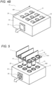
- FIG. 4A illustrates only the cassette stand 2 of FIG. 1 .
- the cassette stand 2 has a circular opening 23 into which a total of nine test tubes, three test tube units having three test tubes, are inserted.
- the slit 22 is provided on one side of each lane corresponding to each test tube unit.
- the lane is along the direction indicated by an arrow 401. Accordingly, the arrow 401 may be referred to as a "lane direction".
- the exhaust fan 25 is installed on the lateral surface 24 of the cassette stand 2.
- FIG. 4B is a perspective view illustrating a modification of the cassette stand.
- an exhaust opening 31 for connecting an exhaust fan is provided on the lateral surface 24 of the cassette stand 2.
- the exhaust fan is installed on a housing side of a genetic testing apparatus (not illustrated) so as to be connected to the exhaust opening 31.
- the slit 14 and the slit 22 communicate with each other, but even in a configuration in which the slit 14 is not provided in the lateral flange 12, a desired effect can be obtained as long as the slit 22 is opened so as to suck the gas above the test tube 15 without being blocked by the lateral flange 12.
- a convex portion may be provided on the lateral flange 12 or the upper surface 21 to float the lateral flange 12.
- the shape of the convex portion may be a rod shape or a dot shape.
- a portion having a large diameter may be provided in a part of a peripheral edge portion of the circular opening 23 into which the test tube 15 is inserted so that the portion is not blocked when the test tube 15 is inserted.
- the slit 22 may be provided at a position not covered by the lateral flange 12.
- the slit 22 is provided on the right side of the right end in the drawing of the lateral flange 12 ( FIG. 2 ). Slits 252 in FIGS. 15 and 16 described later are also included in this type.
- FIG. 6 illustrates a result of simulation in the configuration of the present embodiment.
- This drawing illustrates a result of simulation of the trajectory of the microparticle 6 under an initial condition that a solid or liquid microparticle 6 simulating aerosol or a reagent mist containing nucleic acid molecules is present inside the test tube 15.
- the microparticle 6 moves from the inside of the test tube 15 to the upper side of the test tube 15, passes through the slit 14 and the slit 22 from the upper side of the test tube 15 according to the downflow, moves to the internal space of the cassette stand 2, and is discharged to the outside of the apparatus.
- the arrow 5 schematically represents the trajectory of the microparticle 6.
- FIG. 7 illustrates a case where there is no vertical flange and no slit on the upper surface of the cassette stand.
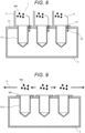
- FIG. 8 illustrates a result of simulation under an initial condition different from that in FIG. 6 in the configuration of the present embodiment.
- the microparticle 806 passes through the slit 14 and the slit 22 from the upper side of the test tube 15 according to the downflow, moves to the internal space of the cassette stand 2, and is discharged to the outside of the apparatus.
- An arrow 8 schematically represents a trajectory of the microparticle 806.
- microparticles containing nucleic acid molecules may be generated from the lower end portion of the dispensing tip installed in the dispensing mechanism, it is desirable that the upper end portion of the vertical flange be higher than the lower end portion of the dispensing tip in consideration of the effect illustrated in this drawing, and it is considered that the cross-contamination preventing effect is high.
- FIG. 9 illustrates a result of simulation in a case where there is a slit but there is no vertical flange.
- the microparticle 906 above the test tube 915 may move in the horizontal direction as indicated by an arrow 9 without the vertical flange.
- the particles coming out of the test tube as the contamination source move to the internal space of the cassette stand, are discharged to the outside of the apparatus, or are captured by the filter, and thus do not return to the upper side of the test tube again. Therefore, occurrence of secondary contamination can also be prevented.
- the present embodiment has an effect of preventing occurrence of cross-contamination in the multi-lane fully automatic genetic testing apparatus.
- FIG. 5 is an exploded perspective view illustrating a reaction unit of a second embodiment.
- the lateral flange 12 of the test tube unit 1 is provided with an arc-shaped opening 514 having a shape along the circular opening 13 provided on the upper surface of the test tube 15.
- the arc-shaped opening 514 (ventilation opening) has a semicircular shape.
- the upper surface 21 of the cassette stand 2 is provided with an arc-shaped opening 522 (ventilation opening).
- the exhaust fan 25 provided in the cassette stand 2 the internal space of the cassette stand 2 has a negative pressure, and downflow can be generated above the test tube unit 1 through the arc-shaped opening 514 and the arc-shaped opening 522. This makes it possible to prevent movement of the microparticles containing the nucleic acid molecules scattered from the individual circular openings 13 in the lane direction.
- FIG. 12 is a perspective view illustrating a reaction unit of a third embodiment.
- small holes 224 (vertical openings) are provided on both sides of the circular opening 13.
- the small hole 224 communicates with a ventilation opening (not illustrated) provided in the upper surface 21 of the cassette stand 2.
- FIG. 13 is a perspective view illustrating a reaction unit of a fourth embodiment.
- a small hole 224 (vertical opening) is provided on one side (opposite side of the vertical flange 11) of the circular opening 13.
- the small hole 224 communicates with a ventilation opening (not illustrated) provided in the upper surface 21 of the cassette stand 2.
- FIG. 14 is a perspective view illustrating a reaction unit of a fifth embodiment.
- slits 234 (vertical openings) are provided at both end portions of the lane.
- the slit 234 communicates with a ventilation opening (not illustrated) provided in the upper surface 21 of the cassette stand 2.
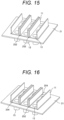
- FIG. 15 is a perspective view illustrating a reaction unit of a sixth embodiment.
- vertical flanges 11 are provided on both sides of the circular opening 13.
- a slit 252 (ventilation opening) is provided on the upper surface 21 of the cassette stand 2 located between the adjacent lanes.
- FIG. 16 is a perspective view illustrating a reaction unit of a seventh embodiment.
- a slit 254 (lateral opening) is provided at the lower portion of the vertical flange 11.
- FIG. 10 illustrates an example of a genetic testing apparatus.
- the genetic testing apparatus includes an apparatus main body 151 and a control terminal 152. A part of the reaction unit can be seen from the window of the apparatus main body 151.
- the control terminal 152 a user can appropriately input an operation condition or the like of the device, and can confirm display of an inspection result or the like.
- FIG. 11 illustrates an internal configuration of the genetic testing apparatus of FIG. 10 .
- each lane eight lanes are provided.
- vertical flanges 171 and 173, test tubes 174, 175, and 176, and the like are arranged in each lane.
Landscapes
- Health & Medical Sciences (AREA)
- Chemical & Material Sciences (AREA)
- Clinical Laboratory Science (AREA)
- Chemical Kinetics & Catalysis (AREA)
- Analytical Chemistry (AREA)
- General Health & Medical Sciences (AREA)
- Hematology (AREA)
- Apparatus Associated With Microorganisms And Enzymes (AREA)
- Automatic Analysis And Handling Materials Therefor (AREA)
Abstract
Description
- The present invention relates to a cassette stand, a reaction unit, and a genetic testing apparatus.
- When genetic information is obtained from a nucleic acid contained in a specimen derived from a living body for the purpose of clinical medicine or diagnosis, a technique for extracting a nucleic acid molecule from the specimen and a quantification technique by amplification of a target sequence are required. A fully automatic genetic testing apparatus that automates a series of these techniques is used in clinical sites.
- Examples of a nucleic acid amplification technique used in the case of inspecting nucleic acid include a method using polymerase chain reaction (hereinafter, it is abbreviated as a "PCR method"). The PCR method is a technique for amplifying a target nucleic acid by increasing or decreasing a temperature using a heat-resistant polymerase and a primer, and is widely used in fields such as genetic engineering, a biological test method, and a detection method. The principle of the PCR method is to increase radii of target DNA in a geometric series by repeating a cycle according to a thermal profile (temperature rising and falling) set in three stages of a first stage in which double-stranded DNA containing a target DNA sequence is maintained at a temperature at which the double-stranded DNA is dissociated into single strands, a second stage in which primers in a forward direction and a reverse direction are maintained at a temperature at which the dissociated single-stranded DNA is annealed, and a third stage in which a DNA strand complementary to the single-stranded DNA is synthesized by DNA polymerase many times.
- Examples of a quantitative test method to which such a PCR method is applied include real-time PCR and quantitative polymerase chain reaction (hereinafter, it is abbreviated as "qPCR". The qPCR method is a highly sensitive genetic analysis method, and has been applied in clinical tests such as quantitative gene expression analysis, pathogen detection, and drug discovery target verification. In the qPCR method, the concentration of the target nucleic acid during amplification is indirectly measured by the intensity of fluorescence reaction light.
- However, the PCR amplification process is sensitive, and even if an extremely small amount of target DNA derived from a specimen other than the specimen to be examined is mixed, amplification occurs in the specimen that is not originally amplified (hereinafter, it is referred to as "false positive amplification"). This false positive amplification affects the accuracy of a fully automated genetic testing apparatus.
- In a case where nucleic acid extraction and PCR sample preparation are manually performed, contamination of the dispensing pipetter and the dispensing tip occurs due to a defect in operation, which may cause false positive amplification. Therefore, it is desirable to perform the test in a clean bench that generates a downward airflow or an upward airflow in the entire room. Thereby, the aerosol containing the nucleic acid molecules generated during the operation is discharged. In the case of a fully automatic genetic testing apparatus, since a test of a plurality of specimens is performed in parallel, aerosol or mist generated by high-speed dispensing spreads in the device, which causes cross-contamination between different specimens.
-
PTL 1 discloses that by using a nucleic acid testing device including a plugging mechanism for covering a dispensing tip for dispensing a reagent and a sample nucleic acid into a reaction container, a heating unit for deactivating an enzyme remaining at a distal end of the dispensing tip, and a tip disposal box, an enzyme attached to the dispensing tip can be deactivated, and unintended amplification, which is a maximum risk of cross-contamination, can be prevented. -
PTL 2 discloses a gas flow path for discharging a gas upward from between a plurality of containers provided on a pallet in an apparatus for performing radiochemical synthesis or analysis and preparation of a radioactive pharmaceutical. -
- PTL 1:
JP 2011-234693 A - PTL 2:
US 2016/0003791 A - In a multi-lane fully automatic genetic testing apparatus used to improve test efficiency, a plurality of reaction lanes and a dispensing mechanism are installed, and different specimens are simultaneously reacted. In such an apparatus, it is efficient to perform a series of operations such as extraction of nucleic acid from a specimen, purification of the extracted nucleic acid, amplification by PCR, and fluorescence detection in the same lane.
- The plurality of lanes is arranged in parallel, and the reagent used in each lane is carried by the dispensing mechanism and injected into the test tube containing the specimen. At this time, since the dispensing tip is inserted into the test tube and a high-speed suction/discharge operation is performed, aerosol and mist containing nucleic acid molecules are generated and move to the adjacent lane, and cross-contamination may occur.
- According to the nucleic acid testing device disclosed in
PTL 1, the enzyme attached to the dispensing tip can be deactivated. However, in a case where the dispensing operation is frequently performed in a state where a plurality of test tubes is placed to be adjacent to each other, this device cannot prevent cross-contamination due to splashes generated in adjacent test tubes. - In the device disclosed in
PTL 2, in a case where a plurality of test tubes is placed to be adjacent to each other, a droplet spray generated by a dispensing operation or the like may fall into an adjacent test tube without being sufficiently discharged only by an upward airflow. In addition, there is a risk that a spray adheres once to a structure provided above the test tube due to an upward airflow, and the spray falls into the test tube before the next inspection to contaminate the sample. - An object of the present invention is to prevent cross-contamination occurring between different specimens and improve test accuracy in a genetic testing apparatus.
- According to an aspect of the present invention, there is provided a reaction unit used in a genetic testing apparatus, the reaction unit including: a test tube unit having a plurality of test tubes or a test tube unit in which a plurality of test tubes can be arranged; and a cassette stand on which the test tube unit is installable, in which a ventilation opening is provided in an upper surface of the cassette stand, and an exhaust fan installed or connected to a lateral surface of the cassette stand sets an internal space of the cassette stand to a negative pressure and generates a downward stream of gas from above the test tubes toward the ventilation opening.
- According to the present invention, in the genetic testing apparatus, it is possible to prevent cross-contamination occurring between different specimens and to improve the test accuracy.
-
- [
FIG. 1] FIG. 1 is an exploded perspective view illustrating a multi-lane type parallel amplification reaction unit constituting a genetic testing apparatus of a first embodiment. - [
FIG. 2] FIG. 2 is a cross-sectional view illustrating a state in which a test tube unit is mounted on a cassette stand in the first embodiment. - [
FIG. 3] FIG. 3 is a perspective view illustrating the test tube unit of the first embodiment. - [
FIG. 4A] FIG. 4A is a perspective view illustrating the cassette stand of the first embodiment. - [
FIG. 4B] FIG. 4B is a perspective view illustrating a modification of the cassette stand ofFIG. 4A . - [
FIG. 5] FIG. 5 is an exploded perspective view illustrating a multi-lane type parallel amplification reaction unit constituting a genetic testing apparatus of a second embodiment. - [
FIG. 6] FIG. 6 is a cross-sectional view illustrating a result of simulation in the configuration of the first embodiment. - [
FIG. 7] FIG. 7 is a cross-sectional view illustrating a result of a simulation in a case where there is no vertical flange and no slit on the upper surface of the cassette stand. - [
FIG. 8] FIG. 8 is a cross-sectional view illustrating a result of simulation under an initial condition different from that inFIG. 6 in the configuration of the present embodiment. - [
FIG. 9] FIG. 9 is a cross-sectional view illustrating a result of a simulation in a case where there is no vertical flange. - [
FIG. 10] FIG. 10 is a perspective view illustrating an example of a genetic testing apparatus. - [
FIG. 11] FIG. 11 is a perspective view illustrating an internal configuration of the genetic testing apparatus ofFIG. 10 . - [
FIG. 12] FIG. 12 is a perspective view illustrating a reaction unit of a third embodiment. - [
FIG. 13] FIG. 13 is a perspective view illustrating a reaction unit of a fourth embodiment. - [
FIG. 14] FIG. 14 is a perspective view illustrating a reaction unit of a fifth embodiment. - [
FIG. 15] FIG. 15 is a perspective view illustrating a reaction unit of a sixth embodiment. - [
FIG. 16] FIG. 16 is a perspective view illustrating a reaction unit of a seventh embodiment. - The present invention relates to a nucleic acid analyzer for analyzing nucleic acid contained in a living body-derived specimen such as blood or urine. The nucleic acid analyzer is a type of genetic testing apparatus. The genetic testing apparatus includes a cassette stand, a reaction unit including the cassette stand, a dispensing tip, and the like.
- Hereinafter, embodiments will be described with reference to the drawings.
-
FIG. 1 illustrates a configuration of a multi-lane type parallel amplification reaction unit constituting a genetic testing apparatus of a first embodiment. In the present specification, the multi-lane type parallel amplification reaction unit is referred to as a "reaction unit". - As illustrated in this drawing, basic elements of the reaction unit include upper
test tube units lower cassette stand 2. Each of thetest tube units test tubes 15, a lateral flange 12 (lateral flange portion) connecting thetest tubes 15, and a vertical flange 11 (vertical flange portion) orthogonal to thelateral flange 12. Thelateral flange 12 and thevertical flange 11 form an L-shaped cross section. Threetest tubes 15 are arranged in thelateral flange 12, and acircular opening 13 is provided on the upper surface of eachtest tube 15. Thelateral flange 12 is provided with a slit 14 (ventilation opening) penetrating thelateral flange 12 in the vicinity of an opposite side of a side where thevertical flange 11 is installed. - The
cassette stand 2 has a rectangular parallelepiped shape having a space therein, and anupper surface 21 is provided with a rectangular slit 22 (ventilation opening) and acircular opening 23 penetrating theupper surface 21. Anexhaust fan 25 is installed on alateral surface 24 of thecassette stand 2. Thecassette stand 2 has a structure having no portion communicating with the outside other than theslit 22, thecircular opening 23, and theexhaust fan 25. Theexhaust fan 25 has a function of exhausting air (gas) inside thecassette stand 2 to the outside. - As illustrated in this drawing, when the
test tube units cassette stand 2, thetest tubes 15 of thetest tube units circular opening 23. Then, theupper surface 21 of thecassette stand 2 comes into contact with thelateral flange 12, and thetest tube units -
FIG. 2 is a cross-sectional view illustrating a state in which the test tube unit is attached to the cassette stand in the present embodiment. - In this drawing, the
slit 14 provided in thelateral flange 12 of each of thetest tube units slit 22 provided in theupper surface 21 of thecassette stand 2 are connected, and the space above thelateral flange 12 and the internal space of thecassette stand 2 communicate with each other. Thetest tube 15 is inserted into a circular opening 23 (FIG. 1 ) provided in theupper surface 21 of thecassette stand 2. Thelateral flange 12 is in contact with theupper surface 21 of thecassette stand 2. Thus, thetest tube units - The internal space of the
cassette stand 2 has a negative pressure by the exhaust fan 25 (FIG. 1 ) provided in thecassette stand 2. The negative pressure sucks air from the space above thetest tube units slit 14 and theslit 22, and generates the downflow 3 (downward airflow) above thetest tube units cassette stand 2 to a negative pressure, there is also an effect of bringing thetest tube units cassette stand 2. - The
vertical flange 11 has a function as a partition plate that divides a space above the lane constituted by thetest tube units vertical flange 11 can also be referred to as a lane partition. Therefore, in the vicinity of the upper surface of thetest tube 15 arranged in each lane, the movement of air to the adjacent lane is restricted. This results in adownflow 3 in each lane. When the dispensing tip for dispensing the reagent is moved up and down, aerosol and mist containing nucleic acid molecules may be generated. However, by setting the position of a lower end portion of the dispensing tip to be equal to or lower than a height of an upper end portion of thevertical flange 11, it is possible to prevent movement of aerosol and mist to the adjacent lane. - The
downflow 3 flows in from above thetest tube units test tube 15, and reaches theslit 14. With this airflow, aerosol and mist containing nucleic acid molecules released from thetest tube 15 are transported to the internal space of thecassette stand 2. Further, the aerosol and the mist are discharged to the outside of the device by the exhaust fan 25 (FIG. 1 ). A filter is installed on the downstream side of theexhaust fan 25 to capture fine particles related to contamination and prevent secondary contamination. - In the present embodiment, a configuration having three lanes is illustrated, but the present invention is not limited thereto, and the number of lanes may be any number. The material of the
cassette stand 2 is not limited, but thetest tube unit 1 is usually made of plastic. -
FIG. 3 is a perspective view illustrating a test tube unit of the present embodiment. - As illustrated in this drawing, one
test tube unit 1 includes threetest tubes 15 and forms one lane. Thevertical flange 11 is installed in parallel to the direction indicated by thearrow 301. Theslit 14 is also provided in parallel to the direction indicated by thearrow 301. In other words, the ventilation opening has a slit shape parallel to the lane of the test tube unit. - In this drawing, a case where there are three
test tubes 15 is illustrated, but there may be any number oftest tubes 15 in onetest tube unit 1 depending on the purpose of use. However, a series oftest tubes 15 arranged in the sametest tube unit 1 is used only in one test for one specimen, discarded after use, and a newtest tube unit 1 is used in a new test. - The three
test tube units FIG. 1 are the same and are similar to thetest tube unit 1 inFIG. 3 . -
FIG. 4A illustrates only thecassette stand 2 ofFIG. 1 . - As illustrated in this drawing, the
cassette stand 2 has acircular opening 23 into which a total of nine test tubes, three test tube units having three test tubes, are inserted. Theslit 22 is provided on one side of each lane corresponding to each test tube unit. The lane is along the direction indicated by anarrow 401. Accordingly, thearrow 401 may be referred to as a "lane direction". - The
exhaust fan 25 is installed on thelateral surface 24 of thecassette stand 2. -
FIG. 4B is a perspective view illustrating a modification of the cassette stand. - In this drawing, an
exhaust opening 31 for connecting an exhaust fan is provided on thelateral surface 24 of thecassette stand 2. The exhaust fan is installed on a housing side of a genetic testing apparatus (not illustrated) so as to be connected to theexhaust opening 31. - In the present embodiment, the
slit 14 and theslit 22 communicate with each other, but even in a configuration in which theslit 14 is not provided in thelateral flange 12, a desired effect can be obtained as long as theslit 22 is opened so as to suck the gas above thetest tube 15 without being blocked by thelateral flange 12. - For example, it is conceivable to provide a gap between the
lateral flange 12 of each of thetest tube units upper surface 21 of thecassette stand 2. In this case, a convex portion may be provided on thelateral flange 12 or theupper surface 21 to float thelateral flange 12. Here, the shape of the convex portion may be a rod shape or a dot shape. In this case, a portion having a large diameter may be provided in a part of a peripheral edge portion of thecircular opening 23 into which thetest tube 15 is inserted so that the portion is not blocked when thetest tube 15 is inserted. - The
slit 22 may be provided at a position not covered by thelateral flange 12. For example, in the present embodiment, theslit 22 is provided on the right side of the right end in the drawing of the lateral flange 12 (FIG. 2 ).Slits 252 inFIGS. 15 and 16 described later are also included in this type. - Next, in order to verify the validity of the configuration of the present embodiment, simulation by numerical calculation was performed on the particle behavior by the air flow. This is a simulation by modeling the configuration in the case of three lanes in the three test tubes illustrated in
FIGS. 1 and2 and using a finite volume method. In this simulation, a condition for setting the internal space of the cassette stand to a negative pressure was given as a setting condition corresponding to the operation of the exhaust fan, and the occurrence of downflow above the test tube unit was simulated. -
FIG. 6 illustrates a result of simulation in the configuration of the present embodiment. - This drawing illustrates a result of simulation of the trajectory of the
microparticle 6 under an initial condition that a solid orliquid microparticle 6 simulating aerosol or a reagent mist containing nucleic acid molecules is present inside thetest tube 15. - As illustrated in this drawing, the
microparticle 6 moves from the inside of thetest tube 15 to the upper side of thetest tube 15, passes through theslit 14 and theslit 22 from the upper side of thetest tube 15 according to the downflow, moves to the internal space of thecassette stand 2, and is discharged to the outside of the apparatus. Thearrow 5 schematically represents the trajectory of themicroparticle 6. - In this simulation, it was found that the movement of the
microparticle 6 to the adjacent lane does not occur in a case where theslit 14 and theslit 22 are provided in each lane. -
FIG. 7 illustrates a case where there is no vertical flange and no slit on the upper surface of the cassette stand. - In this drawing, there is no slit that sucks the upper gas and causes downflow, and there is no vertical flange that restricts the movement of the
microparticle 6 in the horizontal direction. Therefore, as a result of the simulation, it has been confirmed that themicroparticle 6 moves from the inside of thetest tube 715 of thetest tube unit 701 to the adjacent lane and enters the inside of thetest tube 715 as indicated by anarrow 7. -
FIG. 8 illustrates a result of simulation under an initial condition different from that inFIG. 6 in the configuration of the present embodiment. - In this drawing, a result of simulating a trajectory of a
microparticle 806 under an initial condition that themicroparticle 806 is present above thetest tube 15 is illustrated. - As illustrated in this drawing, the
microparticle 806 passes through theslit 14 and theslit 22 from the upper side of thetest tube 15 according to the downflow, moves to the internal space of thecassette stand 2, and is discharged to the outside of the apparatus. Anarrow 8 schematically represents a trajectory of themicroparticle 806. - In this simulation, it was found that when the
vertical flange 11 is provided in each lane, the air flow in the horizontal direction is suppressed, and there is an effect of preventing the movement of themicroparticle 806 to the adjacent lane. In other words, thevertical flange 11 has an effect of preventing further movement of themicroparticle 806 already released above thetest tube 15. - Since microparticles containing nucleic acid molecules may be generated from the lower end portion of the dispensing tip installed in the dispensing mechanism, it is desirable that the upper end portion of the vertical flange be higher than the lower end portion of the dispensing tip in consideration of the effect illustrated in this drawing, and it is considered that the cross-contamination preventing effect is high.
- Note that even with a configuration including only the
slit 14 and theslit 22 without thevertical flange 11, a desired effect can be obtained as long as the internal space of thecassette stand 2 can have a sufficient negative pressure. -
FIG. 9 illustrates a result of simulation in a case where there is a slit but there is no vertical flange. - In this drawing, as in
FIG. 8 , an initial condition that amicroparticle 906 is present above atest tube 915 of thetest tube unit 901 is given. - In this case, when the suction of the gas from the
slit 14 and theslit 22 is insufficient, themicroparticle 906 above thetest tube 915 may move in the horizontal direction as indicated by an arrow 9 without the vertical flange. - Therefore, as illustrated in
FIG. 8 , it is desirable to install thevertical flange 11. - According to the configuration of the present embodiment, the particles coming out of the test tube as the contamination source move to the internal space of the cassette stand, are discharged to the outside of the apparatus, or are captured by the filter, and thus do not return to the upper side of the test tube again. Therefore, occurrence of secondary contamination can also be prevented.
- From the above simulation results, it is considered that the present embodiment has an effect of preventing occurrence of cross-contamination in the multi-lane fully automatic genetic testing apparatus.
-
FIG. 5 is an exploded perspective view illustrating a reaction unit of a second embodiment. - In this drawing, the
lateral flange 12 of thetest tube unit 1 is provided with an arc-shapedopening 514 having a shape along thecircular opening 13 provided on the upper surface of thetest tube 15. The arc-shaped opening 514 (ventilation opening) has a semicircular shape. Theupper surface 21 of thecassette stand 2 is provided with an arc-shaped opening 522 (ventilation opening). By attaching thetest tube unit 1 to thecassette stand 2, the arc-shapedopening 514 and the arc-shapedopening 522 communicate with each other. - Therefore, by the
exhaust fan 25 provided in thecassette stand 2, the internal space of thecassette stand 2 has a negative pressure, and downflow can be generated above thetest tube unit 1 through the arc-shapedopening 514 and the arc-shapedopening 522. This makes it possible to prevent movement of the microparticles containing the nucleic acid molecules scattered from the individualcircular openings 13 in the lane direction. - Next, another example of the reaction unit will be described. In the following description, description of configurations common to the first and second embodiments will be omitted.
-
FIG. 12 is a perspective view illustrating a reaction unit of a third embodiment. - In this drawing, small holes 224 (vertical openings) are provided on both sides of the
circular opening 13. Thesmall hole 224 communicates with a ventilation opening (not illustrated) provided in theupper surface 21 of thecassette stand 2. -
FIG. 13 is a perspective view illustrating a reaction unit of a fourth embodiment. - In this drawing, a small hole 224 (vertical opening) is provided on one side (opposite side of the vertical flange 11) of the
circular opening 13. Thesmall hole 224 communicates with a ventilation opening (not illustrated) provided in theupper surface 21 of thecassette stand 2. -
FIG. 14 is a perspective view illustrating a reaction unit of a fifth embodiment. - In this drawing, slits 234 (vertical openings) are provided at both end portions of the lane. The
slit 234 communicates with a ventilation opening (not illustrated) provided in theupper surface 21 of thecassette stand 2. -
FIG. 15 is a perspective view illustrating a reaction unit of a sixth embodiment. - In this drawing,
vertical flanges 11 are provided on both sides of thecircular opening 13. A slit 252 (ventilation opening) is provided on theupper surface 21 of thecassette stand 2 located between the adjacent lanes. -
FIG. 16 is a perspective view illustrating a reaction unit of a seventh embodiment. - In this drawing, in addition to the configuration of the sixth embodiment, a slit 254 (lateral opening) is provided at the lower portion of the
vertical flange 11. - Hereinafter, the genetic testing apparatus will be described with reference to the drawings.
-
FIG. 10 illustrates an example of a genetic testing apparatus. - In this drawing, the genetic testing apparatus includes an apparatus
main body 151 and acontrol terminal 152. A part of the reaction unit can be seen from the window of the apparatusmain body 151. In thecontrol terminal 152, a user can appropriately input an operation condition or the like of the device, and can confirm display of an inspection result or the like. -
FIG. 11 illustrates an internal configuration of the genetic testing apparatus ofFIG. 10 . - In this drawing, eight lanes are provided. In each lane,
vertical flanges test tubes -
- 1, 1A, 1B, 1C test tube unit
- 2 cassette stand
- 3 downflow
- 5, 7, 8, 9 arrow
- 6, 806, 906 microparticle
- 11 vertical flange
- 12 lateral flange
- 13, 23 circular opening
- 14, 22, 234, 252, 254 slit
- 15 test tube
- 21 upper surface
- 24 lateral surface
- 25 exhaust fan
- 151 apparatus main body
- 152 control terminal
- 224 small hole
- 301, 401 arrow
- 514, 522 arc-shaped opening
Claims (15)
- A cassette stand used in a genetic testing apparatus,
Whereina test tube unit having a plurality of test tubes or a test tube unit in which a plurality of test tubes can be arranged is installable,a ventilation opening is provided in an upper surface of the cassette stand, andan exhaust fan installed or connected to a lateral surface of the cassette stand sets an internal space of the cassette stand to a negative pressure and generates a downward stream of gas from above the test tube toward the ventilation opening. - A reaction unit used in a genetic testing apparatus, the reaction unit comprising:a test tube unit having a plurality of test tubes or a test tube unit in which a plurality of test tubes can be arranged; anda cassette stand on which the test tube unit is installable,whereina ventilation opening is provided in an upper surface of the cassette stand, andan exhaust fan installed or connected to a lateral surface of the cassette stand sets an internal space of the cassette stand to a negative pressure and generates a downward stream of gas from above the test tubes toward the ventilation opening.
- The reaction unit according to claim 2, wherein the test tube unit has a lateral flange portion connecting the plurality of test tubes.
- The reaction unit according to claim 3, wherein the lateral flange portion has a longitudinal opening communicating with the ventilation opening.
- The reaction unit according to claim 3, wherein the lateral flange portion includes a vertical flange portion.
- The reaction unit according to claim 5, wherein the vertical flange portion has a lateral opening.
- The reaction unit according to claim 5, wherein the lateral flange portion and the vertical flange portion form an L-shaped cross section.
- The reaction unit according to claim 2, wherein the ventilation opening has a slit shape parallel to a lane of the test tube unit.
- The reaction unit according to claim 2, wherein the ventilation opening is provided so as to surround an upper portion of the test tubes.
- The reaction unit according to claim 5, wherein the plurality of test tubes is disposed between the ventilation opening and the vertical flange portion.
- The reaction unit according to claim 2, wherein the test tube unit has two vertical flange portions, and
the plurality of test tubes is configured to be disposed between the two vertical flange portions. - The reaction unit according to claim 11, wherein the ventilation opening is provided between two adjacent test tube units.
- The reaction unit according to claim 2, wherein a plurality of the test tube units is installed, and each of the test tube units constitutes a lane.
- A genetic testing apparatus comprising:a test tube unit having a plurality of test tubes or a test tube unit in which a plurality of test tubes can be arranged; anda cassette stand on which the test tube unit is installable,wherein a ventilation opening is provided in an upper surface of the cassette stand, andan exhaust fan installed or connected to a lateral surface of the cassette stand sets an internal space of the cassette stand to a negative pressure and generates a downward stream of gas from above the test tubes toward the ventilation opening.
- The genetic testing apparatus according to claim 14, wherein the exhaust fan is installed in a housing of the genetic testing apparatus.
Applications Claiming Priority (1)
| Application Number | Priority Date | Filing Date | Title |
|---|---|---|---|
| PCT/JP2020/026055 WO2022003915A1 (en) | 2020-07-02 | 2020-07-02 | Cassette stand, reaction unit and genetic testing device |
Publications (2)
| Publication Number | Publication Date |
|---|---|
| EP4177328A1 true EP4177328A1 (en) | 2023-05-10 |
| EP4177328A4 EP4177328A4 (en) | 2024-03-06 |
Family
ID=79315844
Family Applications (1)
| Application Number | Title | Priority Date | Filing Date |
|---|---|---|---|
| EP20942434.0A Pending EP4177328A4 (en) | 2020-07-02 | 2020-07-02 | CASSETTE HOLDER, REACTION UNIT AND GENETIC TESTING DEVICE |
Country Status (5)
| Country | Link |
|---|---|
| US (1) | US20230347352A1 (en) |
| EP (1) | EP4177328A4 (en) |
| JP (1) | JP7375199B2 (en) |
| CN (1) | CN115916946B (en) |
| WO (1) | WO2022003915A1 (en) |
Families Citing this family (2)
| Publication number | Priority date | Publication date | Assignee | Title |
|---|---|---|---|---|
| JP7735579B2 (en) * | 2022-08-09 | 2025-09-08 | 株式会社日立ハイテク | Temperature control device, and biochemical device, analytical device, and genetic testing device equipped with the same |
| EP4575510A4 (en) * | 2022-08-19 | 2026-07-01 | Hitachi High Tech Corp | Dispensing device and genetic testing device so that |
Family Cites Families (12)
| Publication number | Priority date | Publication date | Assignee | Title |
|---|---|---|---|---|
| US3752056A (en) * | 1970-11-04 | 1973-08-14 | Sheldon And Co E | Laboratory exhaust hood |
| US4632022A (en) * | 1985-02-25 | 1986-12-30 | St. Charles Manufacturing Co. | Fume hood fabricated from modules and having laterally extending exhaust ports |
| USD620605S1 (en) * | 2008-01-10 | 2010-07-27 | Reitze Frederick T | Test tube rack |
| JP2011234693A (en) * | 2010-05-13 | 2011-11-24 | Hitachi High-Technologies Corp | Nucleic acid examination apparatus |
| CN201799446U (en) * | 2010-09-30 | 2011-04-20 | 四川峨胜水泥股份有限公司 | Ventilating cabinet of laboratory |
| JP5913071B2 (en) * | 2012-12-05 | 2016-04-27 | 株式会社日立ハイテクノロジーズ | Opening device, sample processing device and container opening method |
| US20150093786A1 (en) * | 2013-09-27 | 2015-04-02 | Eppendorf Ag | Laboratory apparatus and method of using a laboratory apparatus |
| JP6410194B2 (en) * | 2014-07-24 | 2018-10-24 | 国立大学法人九州大学 | Temperature control module and light measurement device |
| WO2018087372A1 (en) * | 2016-11-11 | 2018-05-17 | Laboratorios Alpha San Ignacio Pharma S.L (Alphasip) | System for performing chemical, biological and/or medical processes |
| JP6831539B2 (en) * | 2017-05-22 | 2021-02-17 | 栄研化学株式会社 | Reagent cartridge |
| CN111154642B (en) * | 2020-03-03 | 2024-08-02 | 苏州丰泰医疗科技有限公司 | Automatic nucleic acid extraction and real-time quantitative PCR device and matched reaction box |
| CN118165805B (en) * | 2024-05-13 | 2024-09-06 | 苏州天隆生物科技有限公司 | A multi-drive source kit, amplification detection device and amplification detection method |
-
2020
- 2020-07-02 WO PCT/JP2020/026055 patent/WO2022003915A1/en not_active Ceased
- 2020-07-02 CN CN202080102218.1A patent/CN115916946B/en active Active
- 2020-07-02 EP EP20942434.0A patent/EP4177328A4/en active Pending
- 2020-07-02 JP JP2022532964A patent/JP7375199B2/en active Active
- 2020-07-02 US US18/009,002 patent/US20230347352A1/en active Pending
Also Published As
| Publication number | Publication date |
|---|---|
| US20230347352A1 (en) | 2023-11-02 |
| CN115916946B (en) | 2025-08-05 |
| EP4177328A4 (en) | 2024-03-06 |
| JP7375199B2 (en) | 2023-11-07 |
| JPWO2022003915A1 (en) | 2022-01-06 |
| CN115916946A (en) | 2023-04-04 |
| WO2022003915A1 (en) | 2022-01-06 |
Similar Documents
| Publication | Publication Date | Title |
|---|---|---|
| US10239057B2 (en) | Microfluidic devices and methods for cell analysis and molecular diagnostics | |
| US10252261B2 (en) | Handling liquid samples | |
| US10315195B2 (en) | Device, system and method processing a sample | |
| JP5301610B2 (en) | Apparatus and method for handling fluid for analysis | |
| US11782067B2 (en) | Biologic sample preparation system and related method | |
| US20180230512A1 (en) | Microfluidic Cell Trap and Assay Apparatus for High-Throughput Analysis | |
| JP6039395B2 (en) | Preventing contamination | |
| JP2005509871A (en) | Automated sample preparation method and apparatus | |
| US20230347352A1 (en) | Cassette stand, reaction unit, and genetic testing apparatus | |
| CN101838609A (en) | Sample adding device and application thereof | |
| CN103175977A (en) | Automatic analyzing device | |
| US20250196134A1 (en) | Device And Method For Accelerated Material Extraction And Detection | |
| JP7499340B2 (en) | Biochemical analyzer, reaction unit and cassette guide | |
| CN110982882B (en) | Microfluidic chip for single cell immobilization-isolation and in-situ nucleic acid amplification and application thereof | |
| JP2013208127A (en) | Microreaction vessel, and polymerase chain reaction method using the same | |
| CN115427147A (en) | Apparatus and method for genetic analysis of plant material at a remote test site | |
| JP7172344B2 (en) | Analysis method and analysis apparatus | |
| KR102005507B1 (en) | Integrated DNA Analysis Apparatus | |
| CN111019805A (en) | Microfluidic chip device for fixing single cell and performing medical analysis in situ and application thereof | |
| WO2008001691A1 (en) | Method of treating sample | |
| KR102513521B1 (en) | Cartridge for on-site POC GENE Analysis System | |
| JP5057227B2 (en) | Microchip for blood test | |
| TW202447203A (en) | Automatic sample preparation system | |
| JP2010172270A (en) | Microreaction vessel, and polymerase chain reaction by using the same | |
| Class et al. | Patent application title: Microfluidic Cell Trap and Assay Apparatus for High-Throughput Analysis Inventors: Carl Lars Genoble Hansen (Vancouver, CA) Michael Vaninsberghe (Vancouver, CA) Adam White (Toronto, CA) Oleh Petriv (Vancouver, CA) Tim Leaver (Vancouver, CA) Anupam Singhal (Mississauga, CA) William Bowden (Vancouver, CA) Veronique Lecault (Vancouver, CA) Dan Da Costa (Vancouver, CA) Leo Wu (Surrey, CA) Georgia Russell (Vancouver, CA) Darek Sikorski (Vancouver, CA) |
Legal Events
| Date | Code | Title | Description |
|---|---|---|---|
| STAA | Information on the status of an ep patent application or granted ep patent |
Free format text: STATUS: THE INTERNATIONAL PUBLICATION HAS BEEN MADE |
|
| PUAI | Public reference made under article 153(3) epc to a published international application that has entered the european phase |
Free format text: ORIGINAL CODE: 0009012 |
|
| STAA | Information on the status of an ep patent application or granted ep patent |
Free format text: STATUS: REQUEST FOR EXAMINATION WAS MADE |
|
| 17P | Request for examination filed |
Effective date: 20221208 |
|
| AK | Designated contracting states |
Kind code of ref document: A1 Designated state(s): AL AT BE BG CH CY CZ DE DK EE ES FI FR GB GR HR HU IE IS IT LI LT LU LV MC MK MT NL NO PL PT RO RS SE SI SK SM TR |
|
| DAV | Request for validation of the european patent (deleted) | ||
| DAX | Request for extension of the european patent (deleted) | ||
| A4 | Supplementary search report drawn up and despatched |
Effective date: 20240202 |
|
| RIC1 | Information provided on ipc code assigned before grant |
Ipc: B01L 9/06 20060101ALI20240129BHEP Ipc: B01L 3/00 20060101ALI20240129BHEP Ipc: B01L 9/00 20060101ALI20240129BHEP Ipc: G01N 35/00 20060101ALI20240129BHEP Ipc: C12M 1/00 20060101AFI20240129BHEP |