EP4177147A1 - Garbage collection watercraft - Google Patents
Garbage collection watercraft Download PDFInfo
- Publication number
- EP4177147A1 EP4177147A1 EP22189916.4A EP22189916A EP4177147A1 EP 4177147 A1 EP4177147 A1 EP 4177147A1 EP 22189916 A EP22189916 A EP 22189916A EP 4177147 A1 EP4177147 A1 EP 4177147A1
- Authority
- EP
- European Patent Office
- Prior art keywords
- collection
- collection box
- hull
- watercraft
- garbage
- Prior art date
- Legal status (The legal status is an assumption and is not a legal conclusion. Google has not performed a legal analysis and makes no representation as to the accuracy of the status listed.)
- Granted
Links
Images





Classifications
-
- B—PERFORMING OPERATIONS; TRANSPORTING
- B63—SHIPS OR OTHER WATERBORNE VESSELS; RELATED EQUIPMENT
- B63B—SHIPS OR OTHER WATERBORNE VESSELS; EQUIPMENT FOR SHIPPING
- B63B35/00—Vessels or similar floating structures specially adapted for specific purposes and not otherwise provided for
- B63B35/32—Vessels or similar floating structures specially adapted for specific purposes and not otherwise provided for for collecting pollution from open water
-
- B—PERFORMING OPERATIONS; TRANSPORTING
- B63—SHIPS OR OTHER WATERBORNE VESSELS; RELATED EQUIPMENT
- B63B—SHIPS OR OTHER WATERBORNE VESSELS; EQUIPMENT FOR SHIPPING
- B63B1/00—Hydrodynamic or hydrostatic features of hulls or of hydrofoils
- B63B1/02—Hydrodynamic or hydrostatic features of hulls or of hydrofoils deriving lift mainly from water displacement
- B63B1/10—Hydrodynamic or hydrostatic features of hulls or of hydrofoils deriving lift mainly from water displacement with multiple hulls
- B63B1/12—Hydrodynamic or hydrostatic features of hulls or of hydrofoils deriving lift mainly from water displacement with multiple hulls the hulls being interconnected rigidly
- B63B1/121—Hydrodynamic or hydrostatic features of hulls or of hydrofoils deriving lift mainly from water displacement with multiple hulls the hulls being interconnected rigidly comprising two hulls
-
- E—FIXED CONSTRUCTIONS
- E02—HYDRAULIC ENGINEERING; FOUNDATIONS; SOIL SHIFTING
- E02B—HYDRAULIC ENGINEERING
- E02B15/00—Cleaning or keeping clear the surface of open water; Apparatus therefor
- E02B15/04—Devices for cleaning or keeping clear the surface of open water from oil or like floating materials by separating or removing these materials
- E02B15/10—Devices for removing the material from the surface
-
- B—PERFORMING OPERATIONS; TRANSPORTING
- B63—SHIPS OR OTHER WATERBORNE VESSELS; RELATED EQUIPMENT
- B63B—SHIPS OR OTHER WATERBORNE VESSELS; EQUIPMENT FOR SHIPPING
- B63B1/00—Hydrodynamic or hydrostatic features of hulls or of hydrofoils
- B63B1/02—Hydrodynamic or hydrostatic features of hulls or of hydrofoils deriving lift mainly from water displacement
- B63B1/10—Hydrodynamic or hydrostatic features of hulls or of hydrofoils deriving lift mainly from water displacement with multiple hulls
- B63B1/12—Hydrodynamic or hydrostatic features of hulls or of hydrofoils deriving lift mainly from water displacement with multiple hulls the hulls being interconnected rigidly
- B63B2001/128—Hydrodynamic or hydrostatic features of hulls or of hydrofoils deriving lift mainly from water displacement with multiple hulls the hulls being interconnected rigidly comprising underwater connectors between the hulls
-
- Y—GENERAL TAGGING OF NEW TECHNOLOGICAL DEVELOPMENTS; GENERAL TAGGING OF CROSS-SECTIONAL TECHNOLOGIES SPANNING OVER SEVERAL SECTIONS OF THE IPC; TECHNICAL SUBJECTS COVERED BY FORMER USPC CROSS-REFERENCE ART COLLECTIONS [XRACs] AND DIGESTS
- Y02—TECHNOLOGIES OR APPLICATIONS FOR MITIGATION OR ADAPTATION AGAINST CLIMATE CHANGE
- Y02A—TECHNOLOGIES FOR ADAPTATION TO CLIMATE CHANGE
- Y02A20/00—Water conservation; Efficient water supply; Efficient water use
- Y02A20/20—Controlling water pollution; Waste water treatment
- Y02A20/204—Keeping clear the surface of open water from oil spills
Definitions
- the present invention relates to a garbage collection watercraft.
- a garbage collection watercraft is used to collect garbage floating in the water.
- the garbage collection watercraft is equipped with a collection box and a crane.
- the garbage collection watercraft takes in the garbage into the collection box by moving the collection box in a state of being submerged in the water. Then, by lifting the collection box with the crane, the garbage is collected from the collection box.
- the garbage collection watercraft as described above is a large ship for mounting the crane and the power source for the crane. Therefore, it cannot be used in a narrow place such as a harbor or a waterway. In addition, it is difficult to mount the crane and the power source on a small ship because the loading capacity is limited. Therefore, it is necessary for a worker to manually pull up the collection box, which imposes a heavy burden on the worker.
- An object of the present invention is to provide a garbage collection watercraft that can be reduced in size and can reduce a burden on a worker. According to the present invention said object is solved by a garbage collection watercraft having the features of independent claim 1. Preferred embodiments are laid down in the dependent claims.
- a garbage collection watercraft includes a hull, a collection box, and a buoyant material.
- the collection box includes an intake port for a garbage.
- the collection box is held on the hull so as to be movable between a collection position and a pull-up position.
- the collection box is located at least partially underwater at the collection position.
- the pull-up position is located higher than the collection position.
- the buoyant material is attached to the collection box. The buoyant material raises the collection box from the collection position to the pull-up position by a buoyant force.
- the buoyant force of the buoyant material causes the collection box to move from the collection position to the pull-up position. Because it is not necessary to mount a crane and a power source on the hull, the hull is miniaturized. In addition, the buoyant force of the buoyant material moves the collection box, which reduces the burden on the worker.
- FIG. 1 is a perspective view showing a garbage collection watercraft 1 according to an embodiment.
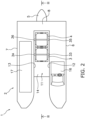
- FIG. 2 is a top view of the garbage collection watercraft 1.
- FIG. 3 is a cross-sectional view taken along the line III-III in FIG. 2 .
- the garbage collection watercraft 1 includes a hull 2 and collection boxes 3 and 4.
- a marine propulsion device 5 is attached to the hull 2.
- the marine propulsion device 5 is, for example, an outboard motor. However, the marine propulsion device 5 may be another propulsion device such as a jet propulsion device.
- the marine propulsion device 5 generates a propulsive force for moving the hull 2.
- the hull 2 includes a first boat 6, a second boat 7, and a connecting portion 8.
- the first boat 6 and the second boat 7 each have a shape extending in a front-rear direction of the hull 2.
- the first boat 6 and the second boat 7 are disposed apart from each other in a left-right direction of the hull 2.
- the connecting portion 8 extends in the left-right direction of the hull 2 and connects the first boat 6 and the second boat 7.
- the hull 2 includes a box storage area 11.
- the box storage area 11 is disposed between the first boat and the second boat 7.
- the box storage area 11 is open toward the front.
- the box storage area 11 is open upward with regard to an up-down direction of the hull 2.
- the box storage area 11 is located between a first inner side surface 12 of the first boat 6 and a second inner side surface 13 of the second boat 7.
- a bottom plate 14 is disposed below the box storage area 11.
- the hull 2 includes a through hole 15.
- the through hole 15 is disposed behind the box storage area 11.
- the through hole 15 extends from the box storage area 11 to the rear of the hull 2.
- the garbage collection watercraft 1 moves forward, water passes between the first boat 6 and the second boat 7 and enters the box storage area 11. The water flows from the box storage area 11 to the rear of the hull 2 through the through hole 15.
- the hull 2 includes a cockpit 16 and a work space 17.
- the work space 17 is disposed adjacent to the box storage area 11.
- the work space 17 is a place for a worker to perform work of pulling up garbage from the collection boxes 3 and 4.
- the cockpit 16 is provided on the first boat 6.
- the work space 17 is provided on the second boat 7.
- the collection boxes 3 and 4 are disposed in the box storage area 11.
- the garbage collection watercraft 1 includes a plurality of collection boxes 3 and 4.
- FIG. 4 is a perspective view of the collection boxes 3 and 4.
- the plurality of collection boxes 3 and 4 include a first collection box 3 and a second collection box 4.
- the first collection box 3 and the second collection box 4 are separate bodies from each other.
- the first collection box 3 includes an intake port 21 for garbage.
- the intake port 21 is provided on the front surface of the first collection box 3.
- Meshes are provided on a rear surface 22, both side surfaces 23 and 24, and a bottom surface 25 of the first collection box 3, respectively.
- An upper surface 26 of the first collection box 3 is open.
- At least one of the side surfaces 23 and 24 of the first collection box 3 may be open.
- a mesh may be provided on the upper surface 26 of the first collection box 3.
- the second collection box 4 has the same structure as the first collection box 3. The second collection box 4 is disposed behind the first collection box 3.
- a first buoyant material 31 is attached to the first collection box 3.
- the first buoyant material 31 is attached to the bottom surface 25 of the first collection box 3.
- the first buoyant material 31 is made of a foamed resin such as urethane. Alternatively, the first buoyant material 31 may be filled with air. The first buoyant material 31 raises the first collection box 3 by the buoyant force.
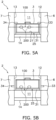
- FIGS. 5A and 5B are front views showing the first collection box 3 in the box storage area 11.
- the first collection box 3 is disposed at the collection position.
- the first collection box 3 is disposed at the pull-up position with regard to up-down direction of the hull 2.
- the pull-up position is located above the collection position.
- the first collection box 3 is movably held by the hull 2 between the collection position and the pull-up position.
- the garbage collection watercraft 1 includes stopper means consisted of stoppers 33 and 34.
- the stoppers 33 and 34 are attached to the hull 2.
- the stoppers 33 and 34 are configured to be switched between a fixed state and a released state.
- the stoppers 33 and 34 fix the first collection box 3 to the hull 2 in the fixed state.
- the stoppers 33 and 34 fix the first collection box 3 by pressing the first collection box 3 from the lateral side.
- the stoppers 33 and 34 may be engaged to the first collection box 3.
- the first collection box 3 is fixed by the stoppers 33 and 34 in a state of being submerged at the collection position.
- the stoppers 33 and 34 hold the first collection box 3 at the collection position against the buoyant force of the first buoyant material 31. In this state, when the garbage collection watercraft 1 moves forward, the underwater garbage 200 enters the first collection box 3 from the intake port 21.
- the stoppers 33 and 34 release the fixing of the first collection box 3 in the released state.
- the first collection box 3 is raised to the pull-up position by the buoyant force of the first buoyant material 31.
- the worker pulls up the garbage 200 from the first collection box 3.
- the first collection box 3 is fixed to the pull-up position by setting the stoppers 33 and 34 to the fixed state while the first collection box 3 is located at the pull-up position. As a result, the first collection box 3 is stably held by the hull 2, so that the work of pulling up the garbage 200 becomes easier.
- a second buoyant material 32 is attached to the second collection box 4.
- the second collection box 4 is movable to the collection position and the pull-up position, and is fixed to the collection position and the pull-up position by stopper means consisted of the stoppers 35 and 36 shown in FIG. 2 . Further, when the stoppers 35 and 36 are in the released state, the second collection box 4 is raised from the collection position to the pull-up position by the buoyant force of the second buoyant material 32.
- the second collection box 4 may be disposed at the collection position while the first collection box 3 is disposed at the pull-up position.
- the underwater garbage 200 is taken into the second collection box 4 while pulling up the garbage 201 from the first collection box 3.
- the first collection box 3 may be disposed at the collection position while the second collection box 4 is disposed at the pull-up position.
- the underwater garbage 200 is taken into the first collection box 3 while pulling up the garbage 201 from the second collection box 4.
- the collection boxes 3 and 4 move from the collection position to the pull-up position due to the buoyant force of the buoyant materials 31 and 32. Therefore, it is not necessary to mount a crane and a power source on the hull 2, and the hull 2 is miniaturized. Further, since the collection boxes 3 and 4 are moved by the buoyant force of the buoyant materials 31 and 32, the burden on the worker in the work of pulling up the garbage from the collection boxes 3 and 4 is reduced.
- the number of collection boxes is not limited to two, and may be one or more than two.
- the plurality of collection boxes may be disposed side by side not only in the front-rear direction but also in the left-right direction.
- the shape of the collection box is not limited to that of the above embodiment, and may be changed.
- a lid 40 configured to open and close the intake port 21 may be attached to the collection box 3.
- a lid may be attached to the collection box 4 as well.
- the lid 40 may be movable between a closed position and an open position.
- the lid 40 closes the intake port 21 in the closed position.
- the lid 40 opens the intake port 21 in the open position.
- the reference numeral 40' indicated by the broken line in FIG. 8 indicates the lid 40 in the open position.
- the lid 40 is slidably attached to the collection box 3.
- the lid 40 may be rotatably attached to the collection box 3.
- the lid 40 may be removable from the collection box 3.
- the structure of the hull 2 is not limited to that of the above embodiment, and may be modified.
- the hull 2 is a so-called catamaran boat, but may be another type of watercraft.
Landscapes
- Engineering & Computer Science (AREA)
- Mechanical Engineering (AREA)
- Combustion & Propulsion (AREA)
- Chemical & Material Sciences (AREA)
- Ocean & Marine Engineering (AREA)
- Environmental & Geological Engineering (AREA)
- General Engineering & Computer Science (AREA)
- Health & Medical Sciences (AREA)
- Public Health (AREA)
- Physics & Mathematics (AREA)
- Fluid Mechanics (AREA)
- Civil Engineering (AREA)
- Structural Engineering (AREA)
- Cleaning Or Clearing Of The Surface Of Open Water (AREA)
Abstract
Description
- The present invention relates to a garbage collection watercraft.
- In recent years, from the perspective of protecting the marine environment toward Sustainable Development Goals (so-called SDGs), activities have been promoted to protect the abundance of the sea by collecting and reducing garbage and microplastics floating on the water. For example, conventionally, there is known a marine garbage collection device that collects garbage floating on the sea by flowing in and collecting the garbage together with seawater (see, for example,
JP 2020-500709 A - In addition, a garbage collection watercraft is used to collect garbage floating in the water. The garbage collection watercraft is equipped with a collection box and a crane. The garbage collection watercraft takes in the garbage into the collection box by moving the collection box in a state of being submerged in the water. Then, by lifting the collection box with the crane, the garbage is collected from the collection box.
- The garbage collection watercraft as described above is a large ship for mounting the crane and the power source for the crane. Therefore, it cannot be used in a narrow place such as a harbor or a waterway. In addition, it is difficult to mount the crane and the power source on a small ship because the loading capacity is limited. Therefore, it is necessary for a worker to manually pull up the collection box, which imposes a heavy burden on the worker. An object of the present invention is to provide a garbage collection watercraft that can be reduced in size and can reduce a burden on a worker. According to the present invention said object is solved by a garbage collection watercraft having the features of
independent claim 1. Preferred embodiments are laid down in the dependent claims. - A garbage collection watercraft according to one aspect of the present disclosure includes a hull, a collection box, and a buoyant material. The collection box includes an intake port for a garbage. The collection box is held on the hull so as to be movable between a collection position and a pull-up position. The collection box is located at least partially underwater at the collection position. The pull-up position is located higher than the collection position. The buoyant material is attached to the collection box. The buoyant material raises the collection box from the collection position to the pull-up position by a buoyant force.
- According to the present teaching, the buoyant force of the buoyant material causes the collection box to move from the collection position to the pull-up position. Because it is not necessary to mount a crane and a power source on the hull, the hull is miniaturized. In addition, the buoyant force of the buoyant material moves the collection box, which reduces the burden on the worker.
-
-
FIG. 1 is a perspective view showing a garbage collection watercraft according to an embodiment. -
FIG. 2 is a top view of the garbage collection watercraft. -
FIG. 3 is a cross-sectional view taken along the line III-III inFIG. 2 . -
FIG. 4 is a perspective view of a collection box. -
FIG. 5A is a front view showing the collection box in a box storage area. -
FIG. 5B is a front view showing the collection box in the box storage area. -
FIG. 6 is a front view showing the collection box in the box storage area. -
FIG. 7A is a side sectional view of the garbage collection watercraft. -
FIG. 7B is a side sectional view of the garbage collection watercraft. -
FIG. 8 is a side sectional view of the garbage collection watercraft according to another embodiment. - Hereinafter, a garbage collection watercraft according to an embodiment will be described with reference to the drawings.
FIG. 1 is a perspective view showing agarbage collection watercraft 1 according to an embodiment.FIG. 2 is a top view of the garbage collection watercraft 1.FIG. 3 is a cross-sectional view taken along the line III-III inFIG. 2 . As shown inFIGS. 1 to 3 , thegarbage collection watercraft 1 includes ahull 2 andcollection boxes - As shown in
FIG. 2 , amarine propulsion device 5 is attached to thehull 2. Themarine propulsion device 5 is, for example, an outboard motor. However, themarine propulsion device 5 may be another propulsion device such as a jet propulsion device. Themarine propulsion device 5 generates a propulsive force for moving thehull 2. - The
hull 2 includes afirst boat 6, asecond boat 7, and a connectingportion 8. Thefirst boat 6 and thesecond boat 7 each have a shape extending in a front-rear direction of thehull 2. Thefirst boat 6 and thesecond boat 7 are disposed apart from each other in a left-right direction of thehull 2. The connectingportion 8 extends in the left-right direction of thehull 2 and connects thefirst boat 6 and thesecond boat 7. - The
hull 2 includes abox storage area 11. Thebox storage area 11 is disposed between the first boat and thesecond boat 7. Thebox storage area 11 is open toward the front. Thebox storage area 11 is open upward with regard to an up-down direction of thehull 2. Thebox storage area 11 is located between a firstinner side surface 12 of thefirst boat 6 and a secondinner side surface 13 of thesecond boat 7. Abottom plate 14 is disposed below thebox storage area 11. - As shown in
FIG. 3 , thehull 2 includes a throughhole 15. The throughhole 15 is disposed behind thebox storage area 11. The throughhole 15 extends from thebox storage area 11 to the rear of thehull 2. As thegarbage collection watercraft 1 moves forward, water passes between thefirst boat 6 and thesecond boat 7 and enters thebox storage area 11. The water flows from thebox storage area 11 to the rear of thehull 2 through the throughhole 15. - The
hull 2 includes acockpit 16 and awork space 17. Thework space 17 is disposed adjacent to thebox storage area 11. Thework space 17 is a place for a worker to perform work of pulling up garbage from thecollection boxes cockpit 16 is provided on thefirst boat 6. Thework space 17 is provided on thesecond boat 7. - The
collection boxes box storage area 11. In the present embodiment, thegarbage collection watercraft 1 includes a plurality ofcollection boxes FIG. 4 is a perspective view of thecollection boxes collection boxes first collection box 3 and asecond collection box 4. Thefirst collection box 3 and thesecond collection box 4 are separate bodies from each other. - The
first collection box 3 includes anintake port 21 for garbage. Theintake port 21 is provided on the front surface of thefirst collection box 3. Meshes are provided on arear surface 22, both side surfaces 23 and 24, and abottom surface 25 of thefirst collection box 3, respectively. Anupper surface 26 of thefirst collection box 3 is open. - At least one of the side surfaces 23 and 24 of the
first collection box 3 may be open. A mesh may be provided on theupper surface 26 of thefirst collection box 3. Thesecond collection box 4 has the same structure as thefirst collection box 3. Thesecond collection box 4 is disposed behind thefirst collection box 3. - A first
buoyant material 31 is attached to thefirst collection box 3. The firstbuoyant material 31 is attached to thebottom surface 25 of thefirst collection box 3. The firstbuoyant material 31 is made of a foamed resin such as urethane. Alternatively, the firstbuoyant material 31 may be filled with air. The firstbuoyant material 31 raises thefirst collection box 3 by the buoyant force. -
FIGS. 5A and 5B are front views showing thefirst collection box 3 in thebox storage area 11. InFIG. 5A , thefirst collection box 3 is disposed at the collection position. InFIG. 5B , thefirst collection box 3 is disposed at the pull-up position with regard to up-down direction of thehull 2. The pull-up position is located above the collection position. Thefirst collection box 3 is movably held by thehull 2 between the collection position and the pull-up position. - As shown in
FIG. 5A , at least a part of thefirst collection box 3 is located underwater at the collection position. Thebottom surface 25 of thefirst collection box 3 is located below thewater surface 100 at the collection position. Thegarbage collection watercraft 1 includes stopper means consisted ofstoppers stoppers hull 2. Thestoppers - As shown in
FIG. 5A , thestoppers first collection box 3 to thehull 2 in the fixed state. For example, thestoppers first collection box 3 by pressing thefirst collection box 3 from the lateral side. Alternatively, thestoppers first collection box 3. - The
first collection box 3 is fixed by thestoppers stoppers first collection box 3 at the collection position against the buoyant force of the firstbuoyant material 31. In this state, when thegarbage collection watercraft 1 moves forward, theunderwater garbage 200 enters thefirst collection box 3 from theintake port 21. - The
stoppers first collection box 3 in the released state. As a result, as shown inFIG. 5B , thefirst collection box 3 is raised to the pull-up position by the buoyant force of the firstbuoyant material 31. In this state, the worker pulls up thegarbage 200 from thefirst collection box 3. - As shown in
FIG. 6 , thefirst collection box 3 is fixed to the pull-up position by setting thestoppers first collection box 3 is located at the pull-up position. As a result, thefirst collection box 3 is stably held by thehull 2, so that the work of pulling up thegarbage 200 becomes easier. - As shown in
FIGS. 3 and4 , a secondbuoyant material 32 is attached to thesecond collection box 4. Like thefirst collection box 3, thesecond collection box 4 is movable to the collection position and the pull-up position, and is fixed to the collection position and the pull-up position by stopper means consisted of thestoppers FIG. 2 . Further, when thestoppers second collection box 4 is raised from the collection position to the pull-up position by the buoyant force of the secondbuoyant material 32. - For example, as shown in
FIG. 7A , thesecond collection box 4 may be disposed at the collection position while thefirst collection box 3 is disposed at the pull-up position. As a result, theunderwater garbage 200 is taken into thesecond collection box 4 while pulling up thegarbage 201 from thefirst collection box 3. Further, as shown inFIG. 7B , thefirst collection box 3 may be disposed at the collection position while thesecond collection box 4 is disposed at the pull-up position. As a result, theunderwater garbage 200 is taken into thefirst collection box 3 while pulling up thegarbage 201 from thesecond collection box 4. - In the
garbage collection watercraft 1 according to the present embodiment described above, thecollection boxes buoyant materials hull 2, and thehull 2 is miniaturized. Further, since thecollection boxes buoyant materials collection boxes - Although one embodiment has been described above, the present teaching is not limited to the above embodiment, and various modifications can be made.
- The number of collection boxes is not limited to two, and may be one or more than two. The plurality of collection boxes may be disposed side by side not only in the front-rear direction but also in the left-right direction. The shape of the collection box is not limited to that of the above embodiment, and may be changed.
- As shown in
FIG. 8 , alid 40 configured to open and close theintake port 21 may be attached to thecollection box 3. A lid may be attached to thecollection box 4 as well. Thelid 40 may be movable between a closed position and an open position. Thelid 40 closes theintake port 21 in the closed position. Thelid 40 opens theintake port 21 in the open position. The reference numeral 40' indicated by the broken line inFIG. 8 indicates thelid 40 in the open position. For example, thelid 40 is slidably attached to thecollection box 3. Alternatively, thelid 40 may be rotatably attached to thecollection box 3. Alternatively, thelid 40 may be removable from thecollection box 3. When thegarbage collection watercraft 1 moves backward, theintake port 21 is closed by thelid 40, so that the backflow of garbage from thecollection box 3 is prevented. - The structure of the
hull 2 is not limited to that of the above embodiment, and may be modified. For example, in the above embodiment, thehull 2 is a so-called catamaran boat, but may be another type of watercraft. -
- 2:
- Hull
- 3, 4:
- Collection box
- 6:
- First boat
- 7:
- Second boat
- 8:
- Connecting portion
- 11:
- Box storage area
- 15:
- Through hole
- 21:
- Intake port
- 31, 32:
- Buoyant material
- 33, 34, 35, 36:
- Stopper
Claims (13)
- A garbage collection watercraft (1) comprising:a hull (2);at least one collection box (3, 4) including an intake port (21) for a garbage, the collection box (3, 4) being movably held by the hull (2) to a collection position in which the collection box (3) is at least partially located underwater and a pull-up position located higher than the collection position with regard to an up-down direction of the hull (2); anda buoyant material (31, 32) that is attached to the collection box (3, 4) and is configured to raise the collection box (3, 4) from the collection position to the pull-up position by a buoyant force.
- The garbage collection watercraft (1) according to claim 1, further comprising:
a stopper means (33, 34, 35, 36) configured to be switched between a first fixed state to fix the collection box (3, 4) to the hull (2) at the collection position and a released state to release the collection box (3, 4). - The garbage collection watercraft (1) according to claim 2, wherein the stopper means (33, 34, 35, 36) is further configured to be switched to a second fixed state to fix the collection box (3, 4) to the hull (2) at the pull-up position.
- The garbage collection watercraft (1) according to at least one of the claims 1 to 3, wherein the intake port (21) is disposed on a front surface of the collection box (3, 4) with regard to a front-rear direction of the hull (2).
- The garbage collection watercraft (1) according to at least one of the claims 1 to 4, wherein the hull (2) includes a box storage area (11) that opens forward with regard to the front-rear direction of the hull (2), and
the collection box (3, 4) is disposed in the box storage area (11). - The garbage collection watercraft (1) according to at least one of the claims 1 to 5, wherein a rear surface (22) of the collection box (3, 4) includes a mesh.
- The garbage collection watercraft (1) according to at least one of the claims 1 to 7, wherein the hull (2) includes a through hole (15) located behind the collection box (3, 4) with regard to the front-rear direction of the hull (2).
- The garbage collection watercraft (1) according to at least one of the claims 1 to 7, wherein the buoyant material (31, 32) is attached to a bottom surface (25) of the collection box (3, 4).
- The garbage collection watercraft (1) according to at least one of the claims 1 to 8, wherein the hull (2) includesa first boat (6),a second boat (7) disposed apart from the first boat (6) in a left-right direction of the hull (2), anda connecting portion (8) that connects the first boat (6) and the second boat (7), andthe collection box (3, 4) is disposed between the first boat (6) and the second boat (7) with regard to a left-right direction the hull (2).
- The garbage collection watercraft (1) according to claim 9, wherein the hull (2) includes a cockpit (16) and a work space (17), the work space (17) is configured as a place for a worker to perform work of pulling up garbage from the collection box (3, 4), wherein the cockpit (16) is provided on the first boat (6) and the work space (17) is provided on the second boat (7).
- The garbage collection watercraft (1) according to at least one of the claims 1 to 10, comprising a lid (40) configured to open and close the intake port (21) is attached to the collection box (3, 4), wherein the lid (40) is movable between a closed position and an open position.
- The garbage collection watercraft (1) according to at least one of the claims 1 to 11, comprising a first collection box (3) and second collection box (4) each including an intake port (21) for a garbage disposed on a front surface of the collection box (3, 4) with regard to a front-rear direction of the hull (2), wherein second collection box (4) is located behind first collection box (3) the with regard to the front-rear direction of the hull (2).
- The garbage collection watercraft (1) according to at least one of the claims 1 to 12, comprising a marine propulsion device (5) attached to the hull (2).
Applications Claiming Priority (1)
| Application Number | Priority Date | Filing Date | Title |
|---|---|---|---|
| JP2021180000A JP7426365B2 (en) | 2021-11-04 | 2021-11-04 | garbage collection boat |
Publications (2)
| Publication Number | Publication Date |
|---|---|
| EP4177147A1 true EP4177147A1 (en) | 2023-05-10 |
| EP4177147B1 EP4177147B1 (en) | 2025-04-30 |
Family
ID=83151485
Family Applications (1)
| Application Number | Title | Priority Date | Filing Date |
|---|---|---|---|
| EP22189916.4A Active EP4177147B1 (en) | 2021-11-04 | 2022-08-11 | Garbage collection watercraft |
Country Status (3)
| Country | Link |
|---|---|
| US (1) | US12459611B2 (en) |
| EP (1) | EP4177147B1 (en) |
| JP (1) | JP7426365B2 (en) |
Families Citing this family (1)
| Publication number | Priority date | Publication date | Assignee | Title |
|---|---|---|---|---|
| CN118770478A (en) * | 2024-07-19 | 2024-10-15 | 江苏建筑职业技术学院 | A comprehensive aquatic environment purification ship |
Citations (6)
| Publication number | Priority date | Publication date | Assignee | Title |
|---|---|---|---|---|
| GB1503459A (en) * | 1976-06-16 | 1978-03-08 | Mitsubishi Heavy Ind Ltd | Boat for collecting floating material |
| EP1177973A2 (en) * | 2000-08-05 | 2002-02-06 | David William Hoskin | Water vessel arrangement |
| JP2008063823A (en) * | 2006-09-07 | 2008-03-21 | Marine Giken:Kk | Floating body device for recovering water-bloom propagation preventive floating material |
| JP2020500709A (en) | 2016-12-08 | 2020-01-16 | シービン ピーティーワイ エルティーディー | Waste collection equipment |
| WO2020083835A1 (en) * | 2018-10-23 | 2020-04-30 | Orcas As | A marine vessel for removing debris particles in a water column |
| CN112591020A (en) * | 2020-12-24 | 2021-04-02 | 浙江海洋大学 | Garbage salvage catamaran |
Family Cites Families (6)
| Publication number | Priority date | Publication date | Assignee | Title |
|---|---|---|---|---|
| JPS5299293U (en) * | 1976-01-26 | 1977-07-27 | ||
| BR112013019185A2 (en) * | 2011-01-27 | 2016-10-04 | José Caraballo Benitez | anti-pollution vessel |
| CN207683728U (en) * | 2017-12-14 | 2018-08-03 | 刘建枫 | Garbage on water categorised collection ship |
| CN111196338B (en) * | 2020-01-10 | 2021-03-02 | 浙江省海洋水产研究所 | Portable ocean micro plastic recovery device |
| CN212582631U (en) * | 2020-03-27 | 2021-02-23 | 深圳市中裕精密技术有限公司 | Floater fishing device for improving water environment |
| CN212332911U (en) * | 2020-06-02 | 2021-01-12 | 广州粤水建设有限公司 | Rubbish fishing device is used in river lake renovation |
-
2021
- 2021-11-04 JP JP2021180000A patent/JP7426365B2/en active Active
-
2022
- 2022-08-11 US US17/885,599 patent/US12459611B2/en active Active
- 2022-08-11 EP EP22189916.4A patent/EP4177147B1/en active Active
Patent Citations (6)
| Publication number | Priority date | Publication date | Assignee | Title |
|---|---|---|---|---|
| GB1503459A (en) * | 1976-06-16 | 1978-03-08 | Mitsubishi Heavy Ind Ltd | Boat for collecting floating material |
| EP1177973A2 (en) * | 2000-08-05 | 2002-02-06 | David William Hoskin | Water vessel arrangement |
| JP2008063823A (en) * | 2006-09-07 | 2008-03-21 | Marine Giken:Kk | Floating body device for recovering water-bloom propagation preventive floating material |
| JP2020500709A (en) | 2016-12-08 | 2020-01-16 | シービン ピーティーワイ エルティーディー | Waste collection equipment |
| WO2020083835A1 (en) * | 2018-10-23 | 2020-04-30 | Orcas As | A marine vessel for removing debris particles in a water column |
| CN112591020A (en) * | 2020-12-24 | 2021-04-02 | 浙江海洋大学 | Garbage salvage catamaran |
Also Published As
| Publication number | Publication date |
|---|---|
| US20230135883A1 (en) | 2023-05-04 |
| EP4177147B1 (en) | 2025-04-30 |
| JP7426365B2 (en) | 2024-02-01 |
| US12459611B2 (en) | 2025-11-04 |
| JP2023068732A (en) | 2023-05-18 |
Similar Documents
| Publication | Publication Date | Title |
|---|---|---|
| CN109878668B (en) | Novel spindle-shaped separating type parent-subsidiary type deep-sea manned submersible | |
| CA2756907C (en) | Unmanned underwater vehicle and method for recovering such vehicle | |
| US20140116312A1 (en) | System And Method For Recovering A Submarine Vehicle | |
| US10604218B2 (en) | Manoeuvring device and method therof | |
| WO2007033384A2 (en) | Launch and recovery system | |
| JP6825177B2 (en) | Underwater equipment input device | |
| EP4177147B1 (en) | Garbage collection watercraft | |
| JP4264357B2 (en) | A flexible ocean-going vessel with a hull adapted to the water surface | |
| JP5975091B2 (en) | Luggage loading ship and luggage loading method | |
| US5325804A (en) | Fuel-efficient watercraft with improved speed, stability, and safety characteristics | |
| KR102086037B1 (en) | ship having apparatus for delaying capsize | |
| CN111924073A (en) | Composite 10,000-meter submersible | |
| KR20210132665A (en) | Water/Underwater Vessels | |
| US7305931B1 (en) | Rigid chambered boat hull with inflatable perimeter | |
| US20080141916A1 (en) | Small Vessel Capable Of High Tow Force | |
| JP2017149291A (en) | Lifting and recovery device and ship | |
| JP2948395B2 (en) | Submersibles equipped with unmanned submersibles | |
| KR102894985B1 (en) | Device that can reduce the speed of floatation underwater | |
| JP7628517B2 (en) | Ships | |
| JP4773741B2 (en) | Underwater vehicle | |
| Lamb | Some guidance for hull form selection for SWATH ships | |
| EP1177973A2 (en) | Water vessel arrangement | |
| GB2644113A (en) | Antenna enclosure | |
| DE102019202427A1 (en) | WATER VEHICLE | |
| CA1161309A (en) | Coupling device for tug-barge vessel |
Legal Events
| Date | Code | Title | Description |
|---|---|---|---|
| PUAI | Public reference made under article 153(3) epc to a published international application that has entered the european phase |
Free format text: ORIGINAL CODE: 0009012 |
|
| STAA | Information on the status of an ep patent application or granted ep patent |
Free format text: STATUS: THE APPLICATION HAS BEEN PUBLISHED |
|
| AK | Designated contracting states |
Kind code of ref document: A1 Designated state(s): AL AT BE BG CH CY CZ DE DK EE ES FI FR GB GR HR HU IE IS IT LI LT LU LV MC MK MT NL NO PL PT RO RS SE SI SK SM TR |
|
| P01 | Opt-out of the competence of the unified patent court (upc) registered |
Effective date: 20230713 |
|
| STAA | Information on the status of an ep patent application or granted ep patent |
Free format text: STATUS: REQUEST FOR EXAMINATION WAS MADE |
|
| 17P | Request for examination filed |
Effective date: 20231103 |
|
| RBV | Designated contracting states (corrected) |
Designated state(s): AL AT BE BG CH CY CZ DE DK EE ES FI FR GB GR HR HU IE IS IT LI LT LU LV MC MK MT NL NO PL PT RO RS SE SI SK SM TR |
|
| GRAP | Despatch of communication of intention to grant a patent |
Free format text: ORIGINAL CODE: EPIDOSNIGR1 |
|
| STAA | Information on the status of an ep patent application or granted ep patent |
Free format text: STATUS: GRANT OF PATENT IS INTENDED |
|
| INTG | Intention to grant announced |
Effective date: 20250122 |
|
| GRAS | Grant fee paid |
Free format text: ORIGINAL CODE: EPIDOSNIGR3 |
|
| GRAA | (expected) grant |
Free format text: ORIGINAL CODE: 0009210 |
|
| STAA | Information on the status of an ep patent application or granted ep patent |
Free format text: STATUS: THE PATENT HAS BEEN GRANTED |
|
| AK | Designated contracting states |
Kind code of ref document: B1 Designated state(s): AL AT BE BG CH CY CZ DE DK EE ES FI FR GB GR HR HU IE IS IT LI LT LU LV MC MK MT NL NO PL PT RO RS SE SI SK SM TR |
|
| REG | Reference to a national code |
Ref country code: CH Ref legal event code: EP Ref country code: GB Ref legal event code: FG4D |
|
| REG | Reference to a national code |
Ref country code: DE Ref legal event code: R096 Ref document number: 602022013811 Country of ref document: DE |
|
| REG | Reference to a national code |
Ref country code: NL Ref legal event code: FP Ref country code: IE Ref legal event code: FG4D |
|
| PGFP | Annual fee paid to national office [announced via postgrant information from national office to epo] |
Ref country code: NL Payment date: 20250821 Year of fee payment: 4 |
|
| REG | Reference to a national code |
Ref country code: AT Ref legal event code: MK05 Ref document number: 1789832 Country of ref document: AT Kind code of ref document: T Effective date: 20250430 |
|
| PG25 | Lapsed in a contracting state [announced via postgrant information from national office to epo] |
Ref country code: PT Free format text: LAPSE BECAUSE OF FAILURE TO SUBMIT A TRANSLATION OF THE DESCRIPTION OR TO PAY THE FEE WITHIN THE PRESCRIBED TIME-LIMIT Effective date: 20250901 Ref country code: ES Free format text: LAPSE BECAUSE OF FAILURE TO SUBMIT A TRANSLATION OF THE DESCRIPTION OR TO PAY THE FEE WITHIN THE PRESCRIBED TIME-LIMIT Effective date: 20250430 Ref country code: FI Free format text: LAPSE BECAUSE OF FAILURE TO SUBMIT A TRANSLATION OF THE DESCRIPTION OR TO PAY THE FEE WITHIN THE PRESCRIBED TIME-LIMIT Effective date: 20250430 |
|
| PGFP | Annual fee paid to national office [announced via postgrant information from national office to epo] |
Ref country code: DE Payment date: 20250820 Year of fee payment: 4 |
|
| REG | Reference to a national code |
Ref country code: LT Ref legal event code: MG9D |
|
| PG25 | Lapsed in a contracting state [announced via postgrant information from national office to epo] |
Ref country code: GR Free format text: LAPSE BECAUSE OF FAILURE TO SUBMIT A TRANSLATION OF THE DESCRIPTION OR TO PAY THE FEE WITHIN THE PRESCRIBED TIME-LIMIT Effective date: 20250731 Ref country code: NO Free format text: LAPSE BECAUSE OF FAILURE TO SUBMIT A TRANSLATION OF THE DESCRIPTION OR TO PAY THE FEE WITHIN THE PRESCRIBED TIME-LIMIT Effective date: 20250730 |
|
| PG25 | Lapsed in a contracting state [announced via postgrant information from national office to epo] |
Ref country code: PL Free format text: LAPSE BECAUSE OF FAILURE TO SUBMIT A TRANSLATION OF THE DESCRIPTION OR TO PAY THE FEE WITHIN THE PRESCRIBED TIME-LIMIT Effective date: 20250430 |
|
| PGFP | Annual fee paid to national office [announced via postgrant information from national office to epo] |
Ref country code: IT Payment date: 20250901 Year of fee payment: 4 |
|
| PG25 | Lapsed in a contracting state [announced via postgrant information from national office to epo] |
Ref country code: BG Free format text: LAPSE BECAUSE OF FAILURE TO SUBMIT A TRANSLATION OF THE DESCRIPTION OR TO PAY THE FEE WITHIN THE PRESCRIBED TIME-LIMIT Effective date: 20250430 |
|
| PG25 | Lapsed in a contracting state [announced via postgrant information from national office to epo] |
Ref country code: HR Free format text: LAPSE BECAUSE OF FAILURE TO SUBMIT A TRANSLATION OF THE DESCRIPTION OR TO PAY THE FEE WITHIN THE PRESCRIBED TIME-LIMIT Effective date: 20250430 |
|
| PG25 | Lapsed in a contracting state [announced via postgrant information from national office to epo] |
Ref country code: AT Free format text: LAPSE BECAUSE OF FAILURE TO SUBMIT A TRANSLATION OF THE DESCRIPTION OR TO PAY THE FEE WITHIN THE PRESCRIBED TIME-LIMIT Effective date: 20250430 |
|
| PGFP | Annual fee paid to national office [announced via postgrant information from national office to epo] |
Ref country code: FR Payment date: 20250828 Year of fee payment: 4 |
|
| PG25 | Lapsed in a contracting state [announced via postgrant information from national office to epo] |
Ref country code: RS Free format text: LAPSE BECAUSE OF FAILURE TO SUBMIT A TRANSLATION OF THE DESCRIPTION OR TO PAY THE FEE WITHIN THE PRESCRIBED TIME-LIMIT Effective date: 20250731 |
|
| PG25 | Lapsed in a contracting state [announced via postgrant information from national office to epo] |
Ref country code: IS Free format text: LAPSE BECAUSE OF FAILURE TO SUBMIT A TRANSLATION OF THE DESCRIPTION OR TO PAY THE FEE WITHIN THE PRESCRIBED TIME-LIMIT Effective date: 20250830 |
|
| PG25 | Lapsed in a contracting state [announced via postgrant information from national office to epo] |
Ref country code: LV Free format text: LAPSE BECAUSE OF FAILURE TO SUBMIT A TRANSLATION OF THE DESCRIPTION OR TO PAY THE FEE WITHIN THE PRESCRIBED TIME-LIMIT Effective date: 20250430 |
|
| PG25 | Lapsed in a contracting state [announced via postgrant information from national office to epo] |
Ref country code: SM Free format text: LAPSE BECAUSE OF FAILURE TO SUBMIT A TRANSLATION OF THE DESCRIPTION OR TO PAY THE FEE WITHIN THE PRESCRIBED TIME-LIMIT Effective date: 20250430 Ref country code: DK Free format text: LAPSE BECAUSE OF FAILURE TO SUBMIT A TRANSLATION OF THE DESCRIPTION OR TO PAY THE FEE WITHIN THE PRESCRIBED TIME-LIMIT Effective date: 20250430 |
|
| PG25 | Lapsed in a contracting state [announced via postgrant information from national office to epo] |
Ref country code: CZ Free format text: LAPSE BECAUSE OF FAILURE TO SUBMIT A TRANSLATION OF THE DESCRIPTION OR TO PAY THE FEE WITHIN THE PRESCRIBED TIME-LIMIT Effective date: 20250430 |
|
| PG25 | Lapsed in a contracting state [announced via postgrant information from national office to epo] |
Ref country code: EE Free format text: LAPSE BECAUSE OF FAILURE TO SUBMIT A TRANSLATION OF THE DESCRIPTION OR TO PAY THE FEE WITHIN THE PRESCRIBED TIME-LIMIT Effective date: 20250430 |
|
| PG25 | Lapsed in a contracting state [announced via postgrant information from national office to epo] |
Ref country code: SK Free format text: LAPSE BECAUSE OF FAILURE TO SUBMIT A TRANSLATION OF THE DESCRIPTION OR TO PAY THE FEE WITHIN THE PRESCRIBED TIME-LIMIT Effective date: 20250430 |
|
| REG | Reference to a national code |
Ref country code: DE Ref legal event code: R097 Ref document number: 602022013811 Country of ref document: DE |
|
| PG25 | Lapsed in a contracting state [announced via postgrant information from national office to epo] |
Ref country code: RO Free format text: LAPSE BECAUSE OF FAILURE TO SUBMIT A TRANSLATION OF THE DESCRIPTION OR TO PAY THE FEE WITHIN THE PRESCRIBED TIME-LIMIT Effective date: 20250430 |
|
| PLBE | No opposition filed within time limit |
Free format text: ORIGINAL CODE: 0009261 |
|
| STAA | Information on the status of an ep patent application or granted ep patent |
Free format text: STATUS: NO OPPOSITION FILED WITHIN TIME LIMIT |
|
| REG | Reference to a national code |
Ref country code: CH Ref legal event code: L10 Free format text: ST27 STATUS EVENT CODE: U-0-0-L10-L00 (AS PROVIDED BY THE NATIONAL OFFICE) Effective date: 20260311 |
|
| REG | Reference to a national code |
Ref country code: CH Ref legal event code: H13 Free format text: ST27 STATUS EVENT CODE: U-0-0-H10-H13 (AS PROVIDED BY THE NATIONAL OFFICE) Effective date: 20260324 |
|
| PG25 | Lapsed in a contracting state [announced via postgrant information from national office to epo] |
Ref country code: MC Free format text: LAPSE BECAUSE OF FAILURE TO SUBMIT A TRANSLATION OF THE DESCRIPTION OR TO PAY THE FEE WITHIN THE PRESCRIBED TIME-LIMIT Effective date: 20250430 |
|
| 26N | No opposition filed |
Effective date: 20260202 |
|
| PG25 | Lapsed in a contracting state [announced via postgrant information from national office to epo] |
Ref country code: LU Free format text: LAPSE BECAUSE OF NON-PAYMENT OF DUE FEES Effective date: 20250811 |
|
| PG25 | Lapsed in a contracting state [announced via postgrant information from national office to epo] |
Ref country code: CH Free format text: LAPSE BECAUSE OF NON-PAYMENT OF DUE FEES Effective date: 20250831 |