EP4177120A1 - Mounting assembly for fixing a component of a vehicle brake system to a vehicle structure and vehicle - Google Patents
Mounting assembly for fixing a component of a vehicle brake system to a vehicle structure and vehicle Download PDFInfo
- Publication number
- EP4177120A1 EP4177120A1 EP21207128.6A EP21207128A EP4177120A1 EP 4177120 A1 EP4177120 A1 EP 4177120A1 EP 21207128 A EP21207128 A EP 21207128A EP 4177120 A1 EP4177120 A1 EP 4177120A1
- Authority
- EP
- European Patent Office
- Prior art keywords
- bushing
- mounting
- collar
- mounting assembly
- vehicle
- Prior art date
- Legal status (The legal status is an assumption and is not a legal conclusion. Google has not performed a legal analysis and makes no representation as to the accuracy of the status listed.)
- Granted
Links
Images


Classifications
-
- B—PERFORMING OPERATIONS; TRANSPORTING
- B60—VEHICLES IN GENERAL
- B60T—VEHICLE BRAKE CONTROL SYSTEMS OR PARTS THEREOF; BRAKE CONTROL SYSTEMS OR PARTS THEREOF, IN GENERAL; ARRANGEMENT OF BRAKING ELEMENTS ON VEHICLES IN GENERAL; PORTABLE DEVICES FOR PREVENTING UNWANTED MOVEMENT OF VEHICLES; VEHICLE MODIFICATIONS TO FACILITATE COOLING OF BRAKES
- B60T17/00—Component parts, details, or accessories of power brake systems not covered by groups B60T8/00, B60T13/00 or B60T15/00, or presenting other characteristic features
-
- B—PERFORMING OPERATIONS; TRANSPORTING
- B60—VEHICLES IN GENERAL
- B60T—VEHICLE BRAKE CONTROL SYSTEMS OR PARTS THEREOF; BRAKE CONTROL SYSTEMS OR PARTS THEREOF, IN GENERAL; ARRANGEMENT OF BRAKING ELEMENTS ON VEHICLES IN GENERAL; PORTABLE DEVICES FOR PREVENTING UNWANTED MOVEMENT OF VEHICLES; VEHICLE MODIFICATIONS TO FACILITATE COOLING OF BRAKES
- B60T7/00—Brake-action initiating means
- B60T7/02—Brake-action initiating means for personal initiation
- B60T7/04—Brake-action initiating means for personal initiation foot actuated
- B60T7/06—Disposition of pedal
-
- B—PERFORMING OPERATIONS; TRANSPORTING
- B60—VEHICLES IN GENERAL
- B60T—VEHICLE BRAKE CONTROL SYSTEMS OR PARTS THEREOF; BRAKE CONTROL SYSTEMS OR PARTS THEREOF, IN GENERAL; ARRANGEMENT OF BRAKING ELEMENTS ON VEHICLES IN GENERAL; PORTABLE DEVICES FOR PREVENTING UNWANTED MOVEMENT OF VEHICLES; VEHICLE MODIFICATIONS TO FACILITATE COOLING OF BRAKES
- B60T11/00—Transmitting braking action from initiating means to ultimate brake actuator without power assistance or drive or where such assistance or drive is irrelevant
- B60T11/10—Transmitting braking action from initiating means to ultimate brake actuator without power assistance or drive or where such assistance or drive is irrelevant transmitting by fluid means, e.g. hydraulic
- B60T11/16—Master control, e.g. master cylinders
-
- B—PERFORMING OPERATIONS; TRANSPORTING
- B60—VEHICLES IN GENERAL
- B60T—VEHICLE BRAKE CONTROL SYSTEMS OR PARTS THEREOF; BRAKE CONTROL SYSTEMS OR PARTS THEREOF, IN GENERAL; ARRANGEMENT OF BRAKING ELEMENTS ON VEHICLES IN GENERAL; PORTABLE DEVICES FOR PREVENTING UNWANTED MOVEMENT OF VEHICLES; VEHICLE MODIFICATIONS TO FACILITATE COOLING OF BRAKES
- B60T11/00—Transmitting braking action from initiating means to ultimate brake actuator without power assistance or drive or where such assistance or drive is irrelevant
- B60T11/10—Transmitting braking action from initiating means to ultimate brake actuator without power assistance or drive or where such assistance or drive is irrelevant transmitting by fluid means, e.g. hydraulic
- B60T11/16—Master control, e.g. master cylinders
- B60T11/18—Connection thereof to initiating means
-
- B—PERFORMING OPERATIONS; TRANSPORTING
- B60—VEHICLES IN GENERAL
- B60T—VEHICLE BRAKE CONTROL SYSTEMS OR PARTS THEREOF; BRAKE CONTROL SYSTEMS OR PARTS THEREOF, IN GENERAL; ARRANGEMENT OF BRAKING ELEMENTS ON VEHICLES IN GENERAL; PORTABLE DEVICES FOR PREVENTING UNWANTED MOVEMENT OF VEHICLES; VEHICLE MODIFICATIONS TO FACILITATE COOLING OF BRAKES
- B60T13/00—Transmitting braking action from initiating means to ultimate brake actuator with power assistance or drive; Brake systems incorporating such transmitting means, e.g. air-pressure brake systems
-
- B—PERFORMING OPERATIONS; TRANSPORTING
- B60—VEHICLES IN GENERAL
- B60T—VEHICLE BRAKE CONTROL SYSTEMS OR PARTS THEREOF; BRAKE CONTROL SYSTEMS OR PARTS THEREOF, IN GENERAL; ARRANGEMENT OF BRAKING ELEMENTS ON VEHICLES IN GENERAL; PORTABLE DEVICES FOR PREVENTING UNWANTED MOVEMENT OF VEHICLES; VEHICLE MODIFICATIONS TO FACILITATE COOLING OF BRAKES
- B60T17/00—Component parts, details, or accessories of power brake systems not covered by groups B60T8/00, B60T13/00 or B60T15/00, or presenting other characteristic features
- B60T17/18—Safety devices; Monitoring
- B60T17/22—Devices for monitoring or checking brake systems; Signal devices
- B60T17/221—Procedure or apparatus for checking or keeping in a correct functioning condition of brake systems
-
- F—MECHANICAL ENGINEERING; LIGHTING; HEATING; WEAPONS; BLASTING
- F16—ENGINEERING ELEMENTS AND UNITS; GENERAL MEASURES FOR PRODUCING AND MAINTAINING EFFECTIVE FUNCTIONING OF MACHINES OR INSTALLATIONS; THERMAL INSULATION IN GENERAL
- F16D—COUPLINGS FOR TRANSMITTING ROTATION; CLUTCHES; BRAKES
- F16D65/00—Parts or details
- F16D65/0006—Noise or vibration control
Definitions
- the present disclosure relates to a mounting assembly for fixing a component of a vehicle brake system to a vehicle structure.
- the present disclosure is directed to a vehicle having such a mounting assembly and a vehicle brake system.
- absorber means are provided in the surroundings of components of vehicle brake systems and especially in the surroundings of brake boosters. These absorber means serve the purpose of attenuating the noise and vibration such that the comfort of the passengers inside the vehicle is not disturbed. In other words, the passenger compartment is isolated from the components of the vehicle brake systems as far as noise and vibrations are concerned.
- the absorber means are costly both in terms of material costs and in terms of labor cost since they need to be installed in the vehicle.
- An objective of the present disclosure is therefore to provide a solution for attenuating noise and vibrations being generated during the operation of a component of a vehicle brake system, the solution being cost-efficient while maintaining a high level of effectiveness.
- a mounting assembly for fixing a component of a vehicle brake system to a vehicle structure
- the mounting assembly comprises a mounting portion of the vehicle structure having a through hole and a mounting element of the vehicle brake system having a through hole.
- a bolt extends through the through hole of the mounting portion and through the through hole of the mounting element.
- the bolt has a SE:TOP bolt head on a first end thereof.
- a nut engages the bolt at a second end portion thereof which is opposed to the first end, wherein the mounting portion is attached to the mounting element via the bolt and the nut.
- an elastic bushing is provided having a bushing body which is arranged in the through hole of the mounting portion or in the through hole of the mounting element.
- the elastic bushing further has a first bushing collar extending from the bushing body in a radial direction.
- the first bushing collar extends on a first axial side of the corresponding mounting portion or mounting element.
- the corresponding mounting portion or mounting element is the mounting portion or mounting element having the through hole in which the bushing body of the elastic bushing is arranged.
- the first axial side is defined with respect to a middle axis of the through hole in which the bushing body is arranged.
- the first bushing collar may for example be interposed between the mounting portion and the mounting element. Since the bushing is elastic, it provides attenuation or dampening as far as noise and vibration are concerned. This is especially the case for the first bushing collar.
- the bushing can be sourced on the market at comparatively low cost. This is especially the case when considering the usual mass production in the automotive industry. Additionally, the bushing is easy to install during the mounting of the components of the vehicle brake system. Consequently, the mounting assembly according to the present disclosure offers a cost-efficient solution for dampening noise and/or vibrations.
- the elastic bushing can have a second bushing collar extending from the bushing body in a radial direction, the second bushing collar being arranged at an end of the bushing body being opposed to the end at which the first bushing collar is provided.
- the bushing has a bushing collar at both of its ends. This means that if the bushing is provided in the through hole of the mounting portion, an elastic bushing collar is provided at both sides of the mounting portion. If the bushing is provided in the through hole of the mounting element, an elastic bushing collar is provided at both sides thereof. In both cases this leads to an effective attenuation of noise and vibration being generated by the operation of the component of the vehicle brake system.
- the second collar may be interposed between the nut and the mounting portion or the mounting element along an axial direction of the elastic bushing.
- the bolt extends through the elastic bushing. Put otherwise, the bushing circumferentially surrounds the bolt. This especially applies to the bushing body. This configuration is very compact.
- the mounting assembly is suitable for being installed in restraint spaces of the vehicle.
- the elastic bushing may be an integral structure.
- the elastic bushing may be designed as one piece. This renders the bushing design simple. Moreover, such a bushing can be installed easily within the mounting assembly.
- the mounting assembly may comprise a rigid bushing having a bushing body extending through the same through hole as the elastic bushing.
- the rigid bushing has a radially protruding bushing collar being arranged at an axial end of the bushing body.
- the bushing collar of the rigid bushing is arranged outside the elastic bushing.
- Such a rigid bushing can be used for compressing the elastic bushing in a defined and at least locally substantially uniform manner. This way, an attenuation characteristic of the elastic bushing can be set.
- vibrations can be fed into the elastic bushing in order to be attenuated.
- the bolt may also extend through the rigid bushing. Again, such a configuration is very compact. Furthermore, the bolt can be used to compress the elastic bushing via the rigid bushing in a defined manner.
- the collar of the rigid bushing may be interposed between the nut and the elastic bushing. Consequently, the rigid bushing occupies a very restraint space only.
- the rigid bushing being opposed to the collar of the rigid bushing may abut against the mounting portion or the mounting element. Consequently, the rigid bushing can be easily arranged in a defined position.
- the mounting portion or the mounting element against which the bushing abuts serves for positioning the rigid bushing.
- the rigid bushing being arranged in a defined position can serve for positioning further elements of the mounting assembly.
- the mounting assembly may additionally comprise a stopper member having a through hole through which the bolt extends.
- the stopper member abuts against the nut and has at least one abutment leg being configured for abutting against the mounting portion or the mounting element.
- the abutment leg can be used for limiting a relative movement of the parts of the mounting assembly with respect to each other.
- a clearance may be provided between an end of the abutment leg and the mounting portion or the mounting element.
- a neutral state of the mounting assembly is to be understood as a state, in which neither noise nor vibration results from the component of the vehicle brake system. This means that the elastic bushing is not deformed beyond the deformation resulting from its mounting within the mounting assembly.
- the clearance thus, defines a range of movement within the mounting assembly being available for further elastic deformation of the elastic bushing. More precisely, the clearance defines a range of relative movement between the mounting portion and the mounting element.
- a dampening material may be arranged in an abutment area of the mounting portion or the mounting element, the abutment area being configured for contacting the abutment leg.
- the stopper member may be formed as a portion of the rigid bushing.
- the stopper member and the rigid bushing are realized as a single part. This leads to a very simple design of the mounting assembly. Moreover, the assembly of the mounting assembly is facilitated since only one part, i.e. the part being both the stopper member and the rigid bushing, needs to be mounted instead of two parts, i.e. the stopper member and the rigid bushing.
- an extension space may be provided radially adjacent to the first bushing collar and/or the second bushing collar of the elastic bushing such that the first bushing collar and/or the second bushing collar can extend into the extension space when being deformed. Consequently, the elastic bushing can freely deform into the extension space. In other words, the deformation of the elastic bushing is not hindered by geometric restraints. Vibration and noise can thus be attenuated in a reliable manner.
- a vehicle comprising a mounting assembly according to the present disclosure and a vehicle brake system.
- a component of the vehicle brake system is fixed to a structure of the vehicle via the mounting assembly. Consequently, noise and vibration resulting from the operation of the component of the vehicle brake system is effectively attenuated in a cost-effective manner.
- the component of the vehicle brake system is a brake booster.
- Figure 1 shows a vehicle 10 having a vehicle brake system 12 being represented in a schematical manner.
- the vehicle brake system 12 comprises a pedal unit 14 reaching into a passenger compartment 16 of the vehicle 10.
- the vehicle brake system 12 has a component 18 being a brake booster which is operationally connected to the pedal unit 14.
- an exemplary front brake caliper 20 being adapted for interacting with a front brake disc 22 is connected to the brake booster 18 via an exemplary first brake line 24.
- An exemplary rear brake caliper 26 is adapted for interacting with a rear brake disc 28.
- the rear brake caliper 26 is connected to the brake booster 18 by an exemplary second brake line 30.
- the brake booster 18 is fixed to the structure 31 of the vehicle 10 by a mounting assembly 32. More precisely, the brake booster 18 is fixed to a separation wall 34 separating a motor compartment 36 from the passenger compartment 16. Sometimes such a separation wall 34 is designated a firewall. The separation wall 34 obviously forms part of the structure 31 the vehicle 10.
- FIG. 2 the brake booster 18 and the pedal unit 14 are shown in more detail. Also the separation wall 34 is visible. Additionally, a dash panel carrier 38 is represented which is also affixed to the separation wall 34.
- FIG. 3 A first example of the mounting assembly 32 will now be explained with reference to Figures 3 and 4 .
- the brake booster 18 is not represented in order to enhance the visibility of the parts of the mounting assembly 32.
- the mounting assembly 32 comprises a mounting portion 40 of the vehicle structure 31.
- the mounting portion 40 is a plate-shaped portion of the separation wall 34.
- the mounting portion 40 has a through hole 42 (cf. Figure 4 ).
- the mounting assembly 32 comprises a mounting element 44 of the vehicle brake system 12.
- the mounting element 44 is a substantially plate-shaped mounting element 44 of the brake booster 18.
- the mounting element 44 has a through hole 46.
- a bolt 48 is provided which extends through both through holes 42, 46.
- the bolt 48 has a bolt head 50 at a first end thereof.
- the bolt head 50 abuts against the mounting portion 40 on a side being opposite the mounting element 44.
- the elastic bushing 54 has a bushing body 56 which extends through the through hole 46 of the mounting element 44.
- the bushing body 56 radially lies against the cylindrical surface forming the circumference of the through hole 46.
- the elastic bushing 54 has a first bushing collar 58 extending from the bushing body 56 in a radial direction.
- the first bushing collar 58 lies against a rim of the through hole 46. Moreover, the first bushing collar 58 is interposed between the mounting portion 40 and the mounting element 44.
- the elastic bushing 54 also has a second bushing collar 60 extending from the bushing body 56 in a radial direction.
- the second bushing collar 60 is located at an opposite end of the bushing body 56 as compared to the first bushing collar 58.
- the second bushing collar 60 also lies against a rim of the through hole 46. However, the rim against which the second bushing collar 60 lies is arranged on an opposite side as compared to the rim against which the first bushing collar 58 lies.
- the second bushing collar 60 is interposed between the nut 52 and the mounting element 44 along an axial direction A of the elastic bushing 54 corresponding to an axial direction of the through holes 42, 46.
- the elastic bushing 54 i.e. the bushing body 56, the first bushing collar 58 and the second bushing collar 60, are formed in one piece.
- the mounting assembly 32 further comprises a rigid bushing 62.
- the rigid bushing 62 has a bushing body 64.
- the bushing body 64 extends through the through hole 46 of the mounting element 44 radially inside the elastic bushing 54.
- the rigid bushing 62 has a radially protruding bushing collar 66 being arranged at an end of the bushing body 64.
- the bushing collar 66 of the rigid bushing 62 is arranged axially outside the second bushing collar 60 of the elastic bushing 54.
- the bushing collar 66 axially lies against the second bushing collar 60.
- the bushing collar 66 of the rigid bushing 62 is interposed between the nut 52 and the elastic bushing 54, more precisely its second bushing collar 60.
- the rigid bushing 62 is arranged within the mounting assembly 32, such that an end 68 thereof being arranged opposite the bushing collar 66 abuts against the mounting portion 40.
- the bolt 48 extends through the center of the rigid bushing 62.
- the bolt 48 also extends through the elastic bushing 54.
- the mounting assembly 32 additionally comprises a stopper member 70 being generally shaped in the form of half-shell and having a through hole 72 through which the bolt 48 extends.
- the stopper member 70 On a first side, the stopper member 70 abuts against the nut 52.
- the stopper member 70 On a second, opposing side, the stopper member 70 abuts against the bushing collar 66 of the rigid bushing 62.
- a central portion of the stopper member 70 is interposed between the nut 52 and the rigid bushing 62.
- the stopper member also has an abutment leg 74 which is configured for abutting against the mounting element 44.
- the abutment leg has a substantially circular shape when considering a middle axis A of the through hole 72 as a center.
- the axial length of the abutment leg 74 differs from its circumference.
- a clearance 76 is provided between an end of the abutment leg 74 and an abutment area 78 of the mounting element 44. This, of course, is only the case in a neutral state of the mounting assembly 32 which is shown in Figures 3 and 4 .
- a dampening material 80 is arranged on the abutment area 78.
- the mounting portion 40 is, thus, attached to the mounting element 44 by means of the bolt 48, the elastic bushing 54, the rigid bushing 62, the stopper member 70 and the nut 52.
- the rigid bushing 62 and the stopper member 70 are rigidly fixed to the mounting portion 40 by the bolt 48 and the nut 52. This is due to the fact that the end 68 of the rigid bushing 62 rigidly abuts against the mounting portion 40 and the stopper member 70 is held rigidly against the rigid bushing 62 by the nut 52.
- the elastic bushing 54 is compressed in a defined manner if the rigid bushing 62 is mounted on the mounting portion 40 such that the end 68 of the rigid bushing abuts against the mounting portion 40.
- a dimension of an axial space being available for the elastic bushing 54 in the mounted condition thus, corresponds to a distance between the end 68 of the rigid bushing 62 and its bushing collar 66.
- the mounting element 44 is able to move in a first axial direction with respect to the mounting portion 40 by compressing the first bushing collar 58.
- the mounting element 44 can move in a second axial direction with respect to the mounting portion 40 by physically compressing the second bushing cover 60.
- the range of movement in the second axial direction is limited by the size of the clearance 76. Once the clearance 76 is overcome, the mounting element 44 abuts against the stopper member 70.
- the mounting element 44 is able to move in a radial direction by deforming the bushing body 56.
- an extension space 82 is provided radially adjacent to the first bushing collar 58 such that the latter can extend into the extension space 82 when being deformed.
- the extension space 82 is a geometrical feature of the mounting element 44.
- the mounting assembly 32 according to the second example only differs from the mounting assembly 32 of the first example in that the stopper member 70 is formed as a portion of the rigid bushing 62. In other words, the stopper member 70 and the rigid bushing 62 are formed as one part.
- stopper member 70 and its abutment leg 74 being formed by prolonging the bushing collar 66 of the rigid bushing 62.
- the mounting element 44 is not only mounted on the mounting portion 40 via the bolt 48 and the nut 52 as has been explained before.
- a second bolt 84 and a second nut 86 are provided.
- Figures 4 and 6 also show the fixation via the respective second bolt 84 and the respective second nut 86.
- the mounting assembly 32 as explained above could be kinematically inverted without departing from the general idea underlying the present disclosure.
Landscapes
- Engineering & Computer Science (AREA)
- Mechanical Engineering (AREA)
- Transportation (AREA)
- General Engineering & Computer Science (AREA)
- Vibration Prevention Devices (AREA)
- Connection Of Plates (AREA)
Abstract
Description
- The present disclosure relates to a mounting assembly for fixing a component of a vehicle brake system to a vehicle structure.
- Moreover, the present disclosure is directed to a vehicle having such a mounting assembly and a vehicle brake system.
- It is known that components of vehicle brake systems generate noise and vibration when being operated. This is especially the case for brake boosters.
- For this reason, usually absorber means are provided in the surroundings of components of vehicle brake systems and especially in the surroundings of brake boosters. These absorber means serve the purpose of attenuating the noise and vibration such that the comfort of the passengers inside the vehicle is not disturbed. In other words, the passenger compartment is isolated from the components of the vehicle brake systems as far as noise and vibrations are concerned.
- However, the absorber means are costly both in terms of material costs and in terms of labor cost since they need to be installed in the vehicle.
- An objective of the present disclosure is therefore to provide a solution for attenuating noise and vibrations being generated during the operation of a component of a vehicle brake system, the solution being cost-efficient while maintaining a high level of effectiveness.
- The problem is at least partially solved or alleviated by the subject matter of the independent claims of the present disclosure, wherein further examples are incorporated in the dependent claims.
- According to a first aspect, there is provided a mounting assembly for fixing a component of a vehicle brake system to a vehicle structure, the mounting assembly comprises a mounting portion of the vehicle structure having a through hole and a mounting element of the vehicle brake system having a through hole. A bolt extends through the through hole of the mounting portion and through the through hole of the mounting element. The bolt has a SE:TOP bolt head on a first end thereof. Moreover, a nut engages the bolt at a second end portion thereof which is opposed to the first end, wherein the mounting portion is attached to the mounting element via the bolt and the nut. Additionally, an elastic bushing is provided having a bushing body which is arranged in the through hole of the mounting portion or in the through hole of the mounting element. The elastic bushing further has a first bushing collar extending from the bushing body in a radial direction. The first bushing collar extends on a first axial side of the corresponding mounting portion or mounting element. In the present context, the corresponding mounting portion or mounting element is the mounting portion or mounting element having the through hole in which the bushing body of the elastic bushing is arranged. The first axial side is defined with respect to a middle axis of the through hole in which the bushing body is arranged. The first bushing collar may for example be interposed between the mounting portion and the mounting element. Since the bushing is elastic, it provides attenuation or dampening as far as noise and vibration are concerned. This is especially the case for the first bushing collar. If it is interposed between the mounting portion and the mounting element, noise and vibration are hindered from being transferred between these elements. Moreover, the bushing can be sourced on the market at comparatively low cost. This is especially the case when considering the usual mass production in the automotive industry. Additionally, the bushing is easy to install during the mounting of the components of the vehicle brake system. Consequently, the mounting assembly according to the present disclosure offers a cost-efficient solution for dampening noise and/or vibrations.
- The elastic bushing can have a second bushing collar extending from the bushing body in a radial direction, the second bushing collar being arranged at an end of the bushing body being opposed to the end at which the first bushing collar is provided. In other words, the bushing has a bushing collar at both of its ends. This means that if the bushing is provided in the through hole of the mounting portion, an elastic bushing collar is provided at both sides of the mounting portion. If the bushing is provided in the through hole of the mounting element, an elastic bushing collar is provided at both sides thereof. In both cases this leads to an effective attenuation of noise and vibration being generated by the operation of the component of the vehicle brake system.
- The second collar may be interposed between the nut and the mounting portion or the mounting element along an axial direction of the elastic bushing. As a consequence of this configuration, noise and or vibration can only be transferred to the nut and the bolt cooperating therewith in a dampened manner. This further hinders noise and vibration from reaching a passenger compartment.
- It is possible that the bolt extends through the elastic bushing. Put otherwise, the bushing circumferentially surrounds the bolt. This especially applies to the bushing body. This configuration is very compact. Thus, the mounting assembly is suitable for being installed in restraint spaces of the vehicle.
- The elastic bushing may be an integral structure. In other words, the elastic bushing may be designed as one piece. This renders the bushing design simple. Moreover, such a bushing can be installed easily within the mounting assembly.
- Additionally, the mounting assembly may comprise a rigid bushing having a bushing body extending through the same through hole as the elastic bushing. The rigid bushing has a radially protruding bushing collar being arranged at an axial end of the bushing body. The bushing collar of the rigid bushing is arranged outside the elastic bushing. Such a rigid bushing can be used for compressing the elastic bushing in a defined and at least locally substantially uniform manner. This way, an attenuation characteristic of the elastic bushing can be set. Moreover, through the rigid bushing, vibrations can be fed into the elastic bushing in order to be attenuated.
- The bolt may also extend through the rigid bushing. Again, such a configuration is very compact. Furthermore, the bolt can be used to compress the elastic bushing via the rigid bushing in a defined manner.
- The collar of the rigid bushing may be interposed between the nut and the elastic bushing. Consequently, the rigid bushing occupies a very restraint space only.
- An end of the rigid bushing being opposed to the collar of the rigid bushing may abut against the mounting portion or the mounting element. Consequently, the rigid bushing can be easily arranged in a defined position. Thus, the mounting portion or the mounting element against which the bushing abuts serves for positioning the rigid bushing. Of course, the rigid bushing being arranged in a defined position can serve for positioning further elements of the mounting assembly.
- The mounting assembly may additionally comprise a stopper member having a through hole through which the bolt extends. The stopper member abuts against the nut and has at least one abutment leg being configured for abutting against the mounting portion or the mounting element. Thus, the stopper member is secured within the mounting assembly by the bolt and the nut. The abutment leg can be used for limiting a relative movement of the parts of the mounting assembly with respect to each other.
- In a neutral state of the mounting assembly, a clearance may be provided between an end of the abutment leg and the mounting portion or the mounting element. In this context, a neutral state of the mounting assembly is to be understood as a state, in which neither noise nor vibration results from the component of the vehicle brake system. This means that the elastic bushing is not deformed beyond the deformation resulting from its mounting within the mounting assembly. The clearance, thus, defines a range of movement within the mounting assembly being available for further elastic deformation of the elastic bushing. More precisely, the clearance defines a range of relative movement between the mounting portion and the mounting element.
- Moreover, a dampening material may be arranged in an abutment area of the mounting portion or the mounting element, the abutment area being configured for contacting the abutment leg. Thus, in a case in which the abutment leg contacts the abutment area, particularly no noise and/or vibrations are generated. This further enhances the comfort of the vehicle's passengers.
- In a variant, the stopper member may be formed as a portion of the rigid bushing. In other words, the stopper member and the rigid bushing are realized as a single part. This leads to a very simple design of the mounting assembly. Moreover, the assembly of the mounting assembly is facilitated since only one part, i.e. the part being both the stopper member and the rigid bushing, needs to be mounted instead of two parts, i.e. the stopper member and the rigid bushing.
- On the mounting portion and/or on the mounting element an extension space may be provided radially adjacent to the first bushing collar and/or the second bushing collar of the elastic bushing such that the first bushing collar and/or the second bushing collar can extend into the extension space when being deformed. Consequently, the elastic bushing can freely deform into the extension space. In other words, the deformation of the elastic bushing is not hindered by geometric restraints. Vibration and noise can thus be attenuated in a reliable manner.
- According to a second aspect, there is provided a vehicle comprising a mounting assembly according to the present disclosure and a vehicle brake system. A component of the vehicle brake system is fixed to a structure of the vehicle via the mounting assembly. Consequently, noise and vibration resulting from the operation of the component of the vehicle brake system is effectively attenuated in a cost-effective manner.
- In an example, the component of the vehicle brake system is a brake booster.
- It should be noted that the above examples may be combined with each other irrespective of the aspect involved.
- These and other aspects of the present disclosure will become apparent from and elucidated with reference to the examples described hereinafter.
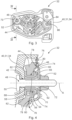
- Examples of the disclosure will be described in the following with reference to the following drawings:
- Fig. 1
- shows a vehicle according to the present disclosure comprising a mounting assembly according to a first example of the present disclosure,
- Fig. 2
- shows a sub-assembly of the vehicle of
Fig. 1 comprising the mounting assembly in a perspective view, - Fig. 3
- shows the mounting assembly along a direction indicated by arrow III in
Figure 2 , wherein remaining components of the sub-assembly ofFigure 2 are not shown, - Fig. 4
- shows a sectional view along plane IV-IV in
Figure 3 , - Fig. 5
- shows a view corresponding to the view of
Fig. 3 comprising a mounting assembly according to a second example of the present disclosure, and - Fig. 6
- shows a sectional view along plane VI-VI in
Fig. 5 . - The figures are merely schematic representations and serve only to illustrate examples of the disclosure. Identical or equivalent elements are in principle provided with the same reference signs.
-
Figure 1 shows avehicle 10 having avehicle brake system 12 being represented in a schematical manner. - The
vehicle brake system 12 comprises apedal unit 14 reaching into apassenger compartment 16 of thevehicle 10. - Furthermore, the
vehicle brake system 12 has acomponent 18 being a brake booster which is operationally connected to thepedal unit 14. - For the ease of explanation, the component of the vehicle brake system and the brake booster will both be designated with
reference sign 18. - Moreover, an exemplary
front brake caliper 20 being adapted for interacting with afront brake disc 22 is connected to thebrake booster 18 via an exemplaryfirst brake line 24. - An exemplary
rear brake caliper 26 is adapted for interacting with arear brake disc 28. Therear brake caliper 26 is connected to thebrake booster 18 by an exemplarysecond brake line 30. - The
brake booster 18 is fixed to the structure 31 of thevehicle 10 by a mountingassembly 32. More precisely, thebrake booster 18 is fixed to a separation wall 34 separating amotor compartment 36 from thepassenger compartment 16. Sometimes such a separation wall 34 is designated a firewall. The separation wall 34 obviously forms part of the structure 31 thevehicle 10. - In
Figure 2 thebrake booster 18 and thepedal unit 14 are shown in more detail. Also the separation wall 34 is visible. Additionally, adash panel carrier 38 is represented which is also affixed to the separation wall 34. - A first example of the mounting
assembly 32 will now be explained with reference toFigures 3 and 4 . In these figures thebrake booster 18 is not represented in order to enhance the visibility of the parts of the mountingassembly 32. - The mounting
assembly 32 comprises a mounting portion 40 of the vehicle structure 31. In the present example the mounting portion 40 is a plate-shaped portion of the separation wall 34. - The mounting portion 40 has a through hole 42 (cf.
Figure 4 ). - Furthermore, the mounting
assembly 32 comprises a mountingelement 44 of thevehicle brake system 12. In the present example, the mountingelement 44 is a substantially plate-shaped mountingelement 44 of thebrake booster 18. - Also the mounting
element 44 has a throughhole 46. - Moreover, a
bolt 48 is provided which extends through both throughholes - The
bolt 48 has abolt head 50 at a first end thereof. - In the present example, the
bolt head 50 abuts against the mounting portion 40 on a side being opposite the mountingelement 44. - At a second end portion of the
bolt 48, which is arranged opposite the first end, andnut 52 is screwed on thebolt 48. This means that an external thread of thebolt 48 engages an internal thread of thenut 50. - Furthermore, and
elastic bushing 54 is provided. - The
elastic bushing 54 has abushing body 56 which extends through the throughhole 46 of the mountingelement 44. - More precisely, the
bushing body 56 radially lies against the cylindrical surface forming the circumference of the throughhole 46. - The
elastic bushing 54 has afirst bushing collar 58 extending from thebushing body 56 in a radial direction. - The
first bushing collar 58 lies against a rim of the throughhole 46. Moreover, thefirst bushing collar 58 is interposed between the mounting portion 40 and the mountingelement 44. - The
elastic bushing 54 also has asecond bushing collar 60 extending from thebushing body 56 in a radial direction. - The
second bushing collar 60 is located at an opposite end of thebushing body 56 as compared to thefirst bushing collar 58. - The
second bushing collar 60 also lies against a rim of the throughhole 46. However, the rim against which thesecond bushing collar 60 lies is arranged on an opposite side as compared to the rim against which thefirst bushing collar 58 lies. - Beyond that, the
second bushing collar 60 is interposed between thenut 52 and the mountingelement 44 along an axial direction A of theelastic bushing 54 corresponding to an axial direction of the throughholes - The
elastic bushing 54, i.e. thebushing body 56, thefirst bushing collar 58 and thesecond bushing collar 60, are formed in one piece. - The mounting
assembly 32 further comprises arigid bushing 62. - Also the
rigid bushing 62 has abushing body 64. - The
bushing body 64 extends through the throughhole 46 of the mountingelement 44 radially inside theelastic bushing 54. - Moreover, the
rigid bushing 62 has a radially protrudingbushing collar 66 being arranged at an end of thebushing body 64. - The
bushing collar 66 of therigid bushing 62 is arranged axially outside thesecond bushing collar 60 of theelastic bushing 54. - The
bushing collar 66 axially lies against thesecond bushing collar 60. - Consequently, the
bushing collar 66 of therigid bushing 62 is interposed between thenut 52 and theelastic bushing 54, more precisely itssecond bushing collar 60. - Moreover, the
rigid bushing 62 is arranged within the mountingassembly 32, such that anend 68 thereof being arranged opposite thebushing collar 66 abuts against the mounting portion 40. - The
bolt 48 extends through the center of therigid bushing 62. - Since the
rigid bushing 62 is arranged at least partially radially inside theelastic bushing 54, thebolt 48 also extends through theelastic bushing 54. - The mounting
assembly 32 additionally comprises astopper member 70 being generally shaped in the form of half-shell and having a throughhole 72 through which thebolt 48 extends. - On a first side, the
stopper member 70 abuts against thenut 52. - On a second, opposing side, the
stopper member 70 abuts against thebushing collar 66 of therigid bushing 62. - Thus, a central portion of the
stopper member 70 is interposed between thenut 52 and therigid bushing 62. - The stopper member also has an
abutment leg 74 which is configured for abutting against the mountingelement 44. - In the present example, the abutment leg has a substantially circular shape when considering a middle axis A of the through
hole 72 as a center. However, the axial length of theabutment leg 74 differs from its circumference. - In order to provide a defined range of motion of the mounting
element 44, aclearance 76 is provided between an end of theabutment leg 74 and anabutment area 78 of the mountingelement 44. This, of course, is only the case in a neutral state of the mountingassembly 32 which is shown inFigures 3 and 4 . - In order to render a potential contact between the
abutment leg 74 and the mountingelement 44 soft, a dampeningmaterial 80 is arranged on theabutment area 78. - The mounting portion 40 is, thus, attached to the mounting
element 44 by means of thebolt 48, theelastic bushing 54, therigid bushing 62, thestopper member 70 and thenut 52. - Thereby, the
rigid bushing 62 and thestopper member 70 are rigidly fixed to the mounting portion 40 by thebolt 48 and thenut 52. This is due to the fact that theend 68 of therigid bushing 62 rigidly abuts against the mounting portion 40 and thestopper member 70 is held rigidly against therigid bushing 62 by thenut 52. - Moreover, the
elastic bushing 54 is compressed in a defined manner if therigid bushing 62 is mounted on the mounting portion 40 such that theend 68 of the rigid bushing abuts against the mounting portion 40. A dimension of an axial space being available for theelastic bushing 54 in the mounted condition, thus, corresponds to a distance between theend 68 of therigid bushing 62 and itsbushing collar 66. - However, the mounting
element 44 is able to move in a first axial direction with respect to the mounting portion 40 by compressing thefirst bushing collar 58. - Additionally, the mounting
element 44 can move in a second axial direction with respect to the mounting portion 40 by physically compressing thesecond bushing cover 60. However, the range of movement in the second axial direction is limited by the size of theclearance 76. Once theclearance 76 is overcome, the mountingelement 44 abuts against thestopper member 70. - Moreover, the mounting
element 44 is able to move in a radial direction by deforming thebushing body 56. - In order not to geometrically limit the elastic deformation of the
elastic bushing 54, anextension space 82 is provided radially adjacent to thefirst bushing collar 58 such that the latter can extend into theextension space 82 when being deformed. - In the present example, the
extension space 82 is a geometrical feature of the mountingelement 44. - During operation of the
brake booster 18, such movements of the mountingelement 44 will be generated as parts of vibrations. Due to the above-explained deformation of theelastic bushing 54, these vibrations are not transferred to the mounting portion 40 or are at least attenuated before being transferred to the mounting portion 40. - A second example of the mounting
assembly 32 will now be explained with reference toFigures 5 and 6 . Again, in these figures thebrake booster 18 is not represented in order to enhance the visibility of the parts of the mountingassembly 32. - The mounting
assembly 32 according to the second example only differs from the mountingassembly 32 of the first example in that thestopper member 70 is formed as a portion of therigid bushing 62. In other words, thestopper member 70 and therigid bushing 62 are formed as one part. - In the second example, one can imagine the
stopper member 70 and itsabutment leg 74 being formed by prolonging thebushing collar 66 of therigid bushing 62. - Beyond that, reference is made to the explanations given in respect of the first example.
- It is noted that in the first example and the second example, the mounting
element 44 is not only mounted on the mounting portion 40 via thebolt 48 and thenut 52 as has been explained before. In both examples asecond bolt 84 and asecond nut 86 are provided. - However, in both examples, the fixation of the mounting
element 44 on the mounting portion 40 via thesecond bolt 84 and thesecond nut 86 is realized in the same manner as the fixation via thebolt 48 and thenut 52. Thus, reference can be made to the above explanations. - In other words, the representations shown in
Figures 4 and6 also show the fixation via the respectivesecond bolt 84 and the respectivesecond nut 86. - It is additionally understood that the mounting
assembly 32 as explained above could be kinematically inverted without departing from the general idea underlying the present disclosure. This means that theelastic bushing 54 and therigid bushing 62 could as well be arranged in the throughhole 42 of the mounting portion 40 and thebolt head 50 could abut against the mountingelement 44. - Other variations to the disclosed examples can be understood and effected by those skilled in the art in practicing the claimed disclosure, from the study of the drawings, the disclosure, and the appended claims. In the claims the word "comprising" does not exclude other elements or steps and the indefinite article "a" or "an" does not exclude a plurality. Any reference signs in the claims should not be construed as limiting the scope of the claims.
-
- 10
- vehicle
- 12
- vehicle brake system
- 14
- pedal unit
- 16
- passenger compartment
- 18
- component of the vehicle brake system
- 20
- front brake caliper
- 22
- front brake disk
- 24
- first brake line
- 26
- rear brake caliper
- 28
- rear brake disk
- 30
- second brake line
- 31
- vehicle structure
- 32
- mounting assembly
- 34
- separation wall
- 36
- motor compartment
- 38
- dash panel carrier
- 40
- mounting portion
- 42
- trough hole
- 44
- mounting element
- 46
- through hole
- 48
- bolt
- 50
- bolt head
- 52
- nut
- 54
- elastic bushing
- 56
- bushing body
- 58
- first bushing collar
- 60
- second bushing collar
- 62
- rigid bushing
- 64
- bushing body
- 66
- bushing collar
- 68
- end
- 70
- stopper member
- 72
- through hole
- 74
- abutment leg
- 76
- clearance
- 78
- abutment area
- 80
- dampening material
- 82
- extension space
- 84
- second bolt
- 86
- second nut
Claims (15)
- A mounting assembly (32) for fixing a component (18) of a vehicle brake system (12) to a vehicle structure (31), the mounting assembly (32) comprising:a mounting portion (40) of the vehicle structure (31) having a through hole (42),a mounting element (44) of the vehicle brake system (12) having a through hole (46),a bolt (48) extending through the through hole (42) of the mounting portion (40) and the through hole (46) of the mounting element (44), the bolt (48) having a bolt head (50) on a first end thereof,a nut (52) engaging the bolt (48) at a second end portion thereof which is opposed to the first end, wherein the mounting portion (40) is attached to the mounting element (44) via the bolt (48) and the nut (52), andan elastic bushing (54) having a bushing body (56) which is arranged in the through hole (42) of the mounting portion (40) or in the through hole (46) of the mounting element (44), and a first bushing collar (58) extending from the bushing body (56) in a radial direction, the first bushing collar (58) extending on a first axial side of the corresponding mounting portion (40) or mounting element (44).
- The mounting assembly (32) according to claim 1, wherein the elastic bushing (54) has a second bushing collar (60) extending from the bushing body (56) in a radial direction, the second bushing collar (60) being arranged at an end of the bushing body (56) being opposed to the end at which the first bushing collar (58) is provided.
- The mounting assembly (32) according to claim 2, wherein the second bushing collar (60) is interposed between the nut (52) and the mounting portion (40) or the mounting element (44) along an axial direction of the elastic bushing (54).
- The mounting assembly (32) according to any one of the preceding claims, wherein the bolt (48) extends through the elastic bushing (54).
- The mounting assembly (32) according to any one of the preceding claims, wherein the elastic bushing (54) is an integral structure.
- The mounting assembly (32) according to any one of the preceding claims, comprising a rigid bushing (62) having a bushing body (64) extending through the same through hole (42, 46) as the elastic bushing (54) and a radially protruding bushing collar (66) being arranged at an axial end of the bushing body (64), the bushing collar (66) of the rigid bushing (62) being arranged outside the elastic bushing (54).
- The mounting assembly (32) according to claim 6, wherein the bolt (48) extends through the rigid bushing (62).
- The mounting assembly (32) according to claim 6 or 7, wherein the collar (66) of the rigid bushing (62) is interposed between the nut (52) and the elastic bushing (54).
- The mounting assembly (32) according to any one of claims 6 to 8, wherein an end (68) of the rigid bushing (62) being opposed to the collar (66) of the rigid bushing (62) abuts against the mounting portion (40) or the mounting element (44).
- The mounting assembly (32) according to any one of the preceding claims, comprising a stopper member (70) having a through hole (72) through which the bolt (48) extends, the stopper member (70) abutting against the nut (52) and having at least one abutment leg (74) being configured for abutting against the mounting portion (40) or the mounting element (44).
- The mounting assembly (32) according to claim 10, wherein in a neutral state of the mounting assembly (32), a clearance (76) is provided between an end of the abutment leg (74) and the mounting portion (40) or the mounting element (44).
- The mounting assembly (32) according to claim 10 or 11, wherein a dampening material (80) is arranged in an abutment area (78) of the mounting portion (40) or the mounting element (44), the abutment area (78) being configured for contacting the abutment leg (74).
- The mounting assembly (32) according to any one of claims 10 to 12 and any one of claims 6 to 9, wherein the stopper member (70) is formed as a portion of the rigid bushing (62).
- The mounting assembly (32) according to any one of the preceding claims, wherein on the mounting portion (40) and/or on the mounting element (44) an extension space (82) is provided radially adjacent to the first bushing collar (58) and/or the second bushing collar (60) of the elastic bushing (54) such that the first bushing collar (58) and/or the second bushing collar (60) can extend into the extension space (82) when being deformed.
- A vehicle (10) comprising a mounting assembly (32) according to any one of the preceding claims and a vehicle brake system (12), characterized in that a component (18) of the vehicle brake system (12) is fixed to a structure of the vehicle (10) via the mounting assembly (32).
Priority Applications (3)
| Application Number | Priority Date | Filing Date | Title |
|---|---|---|---|
| EP21207128.6A EP4177120B1 (en) | 2021-11-09 | 2021-11-09 | Mounting assembly for fixing a component of a vehicle brake system to a vehicle structure and vehicle |
| US17/965,856 US20230144133A1 (en) | 2021-11-09 | 2022-10-14 | Mounting assembly for fixing a component of a vehicle brake system to a vehicle structure and vehicle |
| CN202211361569.1A CN116101250B (en) | 2021-11-09 | 2022-11-02 | Mounting components used to secure vehicle braking system parts to the vehicle structure and vehicle |
Applications Claiming Priority (1)
| Application Number | Priority Date | Filing Date | Title |
|---|---|---|---|
| EP21207128.6A EP4177120B1 (en) | 2021-11-09 | 2021-11-09 | Mounting assembly for fixing a component of a vehicle brake system to a vehicle structure and vehicle |
Publications (2)
| Publication Number | Publication Date |
|---|---|
| EP4177120A1 true EP4177120A1 (en) | 2023-05-10 |
| EP4177120B1 EP4177120B1 (en) | 2024-08-28 |
Family
ID=78592603
Family Applications (1)
| Application Number | Title | Priority Date | Filing Date |
|---|---|---|---|
| EP21207128.6A Active EP4177120B1 (en) | 2021-11-09 | 2021-11-09 | Mounting assembly for fixing a component of a vehicle brake system to a vehicle structure and vehicle |
Country Status (3)
| Country | Link |
|---|---|
| US (1) | US20230144133A1 (en) |
| EP (1) | EP4177120B1 (en) |
| CN (1) | CN116101250B (en) |
Citations (10)
| Publication number | Priority date | Publication date | Assignee | Title |
|---|---|---|---|---|
| US4130027A (en) * | 1976-06-04 | 1978-12-19 | Betty Leighton | Resilient lever assembly |
| US5829317A (en) * | 1997-01-07 | 1998-11-03 | Transnav, Inc. | Brake pedal assembly |
| DE10039808A1 (en) * | 2000-08-16 | 2002-02-28 | Volkswagen Ag | Plastic journal bearing bushing for support of a motor vehicle pedal on its axle, has a hollow construction allowing easy compressibility and so reducing machining tolerances in the associated parts |
| US7051643B1 (en) * | 2004-04-10 | 2006-05-30 | Kelsey-Hayes Company | Retainer for mounting a brake booster |
| CN201511950U (en) * | 2009-07-21 | 2010-06-23 | 上海通用汽车有限公司 | Automobile brake pedal |
| JP2017016401A (en) * | 2015-07-01 | 2017-01-19 | マツダ株式会社 | Pedal retreat prevention structure of vehicle |
| CN208813174U (en) * | 2018-09-28 | 2019-05-03 | 重庆长安汽车股份有限公司 | A kind of automobile brake pedal arm denoising structure |
| CN210941646U (en) * | 2019-10-12 | 2020-07-07 | 中国第一汽车股份有限公司 | ESC module installing support and vehicle |
| CN211852632U (en) * | 2020-01-09 | 2020-11-03 | 桐城市超越橡塑有限公司 | Noise-reducing and shock-absorbing rubber |
| CN213473099U (en) * | 2020-10-19 | 2021-06-18 | 奇瑞商用车(安徽)有限公司 | Brake pedal abnormal sound optimization structure |
Family Cites Families (14)
| Publication number | Priority date | Publication date | Assignee | Title |
|---|---|---|---|---|
| US4624585A (en) * | 1984-02-09 | 1986-11-25 | Automotive Products Plc | Retainer bushing |
| US6189437B1 (en) * | 1999-08-30 | 2001-02-20 | Robert Bosch Corporation | Brake booster having means for mounting on a wall |
| DE102009016633A1 (en) * | 2008-11-26 | 2010-05-27 | Illinois Tool Works Inc., Glenview | Fastening means for pre-assembly of a pin-shaped connecting means in a passage opening of a component |
| DE102009029569A1 (en) * | 2009-09-18 | 2011-03-31 | Robert Bosch Gmbh | Device for the vibration-damping mounting of a fluid aggregate and associated fluid aggregate |
| DE102009060204A1 (en) * | 2009-12-23 | 2011-06-30 | Lucas Automotive GmbH, 56070 | Disc brake for a motor vehicle and brake pad assembly therefor |
| KR101242645B1 (en) * | 2011-02-15 | 2013-03-19 | 주식회사 만도 | Booster assembly for vehicle |
| WO2014169121A1 (en) * | 2013-04-10 | 2014-10-16 | KSR IP Holdings, LLC | Mounting assembly for electronic throttle control assembly |
| JP6100213B2 (en) * | 2014-07-25 | 2017-03-22 | 豊田鉄工株式会社 | Bearing structure of pedal device for vehicle and bush with hook |
| JP6155236B2 (en) * | 2014-08-05 | 2017-06-28 | 豊田鉄工株式会社 | Bearing structure and bush of pedal device for vehicle |
| US10081245B2 (en) * | 2016-06-24 | 2018-09-25 | GM Global Technology Operations LLC | Cradle to body joint release mechanism |
| US10363789B2 (en) * | 2016-07-07 | 2019-07-30 | The Pullman Company | Top mount assembly with bushing having integral anti-vibration feature |
| JP6574748B2 (en) * | 2016-10-18 | 2019-09-11 | 豊田鉄工株式会社 | Bush and vehicle pedal device |
| KR102674663B1 (en) * | 2019-04-15 | 2024-06-12 | 현대자동차주식회사 | Hinge bush for vehicle pedal apparatus |
| DE102020109453A1 (en) * | 2020-04-03 | 2021-10-07 | Zf Active Safety Gmbh | Electrically controllable actuation unit for a motor vehicle brake system, brake booster with such an electrically controllable actuation unit and motor vehicle brake system with such a brake booster |
-
2021
- 2021-11-09 EP EP21207128.6A patent/EP4177120B1/en active Active
-
2022
- 2022-10-14 US US17/965,856 patent/US20230144133A1/en not_active Abandoned
- 2022-11-02 CN CN202211361569.1A patent/CN116101250B/en active Active
Patent Citations (10)
| Publication number | Priority date | Publication date | Assignee | Title |
|---|---|---|---|---|
| US4130027A (en) * | 1976-06-04 | 1978-12-19 | Betty Leighton | Resilient lever assembly |
| US5829317A (en) * | 1997-01-07 | 1998-11-03 | Transnav, Inc. | Brake pedal assembly |
| DE10039808A1 (en) * | 2000-08-16 | 2002-02-28 | Volkswagen Ag | Plastic journal bearing bushing for support of a motor vehicle pedal on its axle, has a hollow construction allowing easy compressibility and so reducing machining tolerances in the associated parts |
| US7051643B1 (en) * | 2004-04-10 | 2006-05-30 | Kelsey-Hayes Company | Retainer for mounting a brake booster |
| CN201511950U (en) * | 2009-07-21 | 2010-06-23 | 上海通用汽车有限公司 | Automobile brake pedal |
| JP2017016401A (en) * | 2015-07-01 | 2017-01-19 | マツダ株式会社 | Pedal retreat prevention structure of vehicle |
| CN208813174U (en) * | 2018-09-28 | 2019-05-03 | 重庆长安汽车股份有限公司 | A kind of automobile brake pedal arm denoising structure |
| CN210941646U (en) * | 2019-10-12 | 2020-07-07 | 中国第一汽车股份有限公司 | ESC module installing support and vehicle |
| CN211852632U (en) * | 2020-01-09 | 2020-11-03 | 桐城市超越橡塑有限公司 | Noise-reducing and shock-absorbing rubber |
| CN213473099U (en) * | 2020-10-19 | 2021-06-18 | 奇瑞商用车(安徽)有限公司 | Brake pedal abnormal sound optimization structure |
Also Published As
| Publication number | Publication date |
|---|---|
| CN116101250B (en) | 2026-03-31 |
| US20230144133A1 (en) | 2023-05-11 |
| CN116101250A (en) | 2023-05-12 |
| EP4177120B1 (en) | 2024-08-28 |
Similar Documents
| Publication | Publication Date | Title |
|---|---|---|
| US11161472B2 (en) | Coupling device for the attachment of an airbag module to a vehicle steering wheel in an oscillatory manner | |
| US12123474B2 (en) | Elastomer bearing for attaching an assembly in a vehicle | |
| EP2085290B1 (en) | Vibration reducing structure for steering wheel | |
| JP3354559B2 (en) | Steering wheel with airbag module | |
| US8556292B2 (en) | Damping system for steering wheel | |
| JP5906251B2 (en) | Mounting structure for vehicle damper | |
| JP3427188B2 (en) | Automotive engine mount | |
| US11325644B2 (en) | Steering wheel assembly | |
| EP1842701A1 (en) | Strut mount assembly | |
| US8375843B2 (en) | Brake booster device with damping element | |
| WO2021219462A1 (en) | A vibration damper assembly, a method of tuning such an assembly, and a method for manufacturing vibration damper assemblies | |
| EP4177120B1 (en) | Mounting assembly for fixing a component of a vehicle brake system to a vehicle structure and vehicle | |
| US10518805B2 (en) | Knuckle apparatus for vehicle suspension system | |
| US10543823B2 (en) | Pneumatic brake booster having a recessed bearing surface | |
| JP3753065B2 (en) | Elastic seal ring | |
| JP2011020589A (en) | Vehicular suspension device | |
| JP4963401B2 (en) | Strut mount | |
| US20230085537A1 (en) | Coupling device for securing an airbag module to a vehicle steering wheel | |
| US10300893B2 (en) | Brake boosting device | |
| CN111316012B (en) | Subframe of motor vehicle | |
| US20210379949A1 (en) | Vibration attenuation assembly | |
| JPH0989046A (en) | Engine mount | |
| JP3334436B2 (en) | Strut mount | |
| JP2003182332A (en) | Seal structure | |
| JP2020159449A (en) | Bracket for tubular anti-vibration device |
Legal Events
| Date | Code | Title | Description |
|---|---|---|---|
| PUAI | Public reference made under article 153(3) epc to a published international application that has entered the european phase |
Free format text: ORIGINAL CODE: 0009012 |
|
| STAA | Information on the status of an ep patent application or granted ep patent |
Free format text: STATUS: REQUEST FOR EXAMINATION WAS MADE |
|
| 17P | Request for examination filed |
Effective date: 20220628 |
|
| AK | Designated contracting states |
Kind code of ref document: A1 Designated state(s): AL AT BE BG CH CY CZ DE DK EE ES FI FR GB GR HR HU IE IS IT LI LT LU LV MC MK MT NL NO PL PT RO RS SE SI SK SM TR |
|
| STAA | Information on the status of an ep patent application or granted ep patent |
Free format text: STATUS: EXAMINATION IS IN PROGRESS |
|
| 17Q | First examination report despatched |
Effective date: 20230524 |
|
| GRAP | Despatch of communication of intention to grant a patent |
Free format text: ORIGINAL CODE: EPIDOSNIGR1 |
|
| STAA | Information on the status of an ep patent application or granted ep patent |
Free format text: STATUS: GRANT OF PATENT IS INTENDED |
|
| INTG | Intention to grant announced |
Effective date: 20240426 |
|
| GRAS | Grant fee paid |
Free format text: ORIGINAL CODE: EPIDOSNIGR3 |
|
| GRAA | (expected) grant |
Free format text: ORIGINAL CODE: 0009210 |
|
| STAA | Information on the status of an ep patent application or granted ep patent |
Free format text: STATUS: THE PATENT HAS BEEN GRANTED |
|
| AK | Designated contracting states |
Kind code of ref document: B1 Designated state(s): AL AT BE BG CH CY CZ DE DK EE ES FI FR GB GR HR HU IE IS IT LI LT LU LV MC MK MT NL NO PL PT RO RS SE SI SK SM TR |
|
| REG | Reference to a national code |
Ref country code: CH Ref legal event code: EP |
|
| P01 | Opt-out of the competence of the unified patent court (upc) registered |
Free format text: CASE NUMBER: APP_45296/2024 Effective date: 20240805 |
|
| REG | Reference to a national code |
Ref country code: DE Ref legal event code: R096 Ref document number: 602021017852 Country of ref document: DE |
|
| REG | Reference to a national code |
Ref country code: IE Ref legal event code: FG4D |
|
| REG | Reference to a national code |
Ref country code: LT Ref legal event code: MG9D |
|
| PG25 | Lapsed in a contracting state [announced via postgrant information from national office to epo] |
Ref country code: NO Free format text: LAPSE BECAUSE OF FAILURE TO SUBMIT A TRANSLATION OF THE DESCRIPTION OR TO PAY THE FEE WITHIN THE PRESCRIBED TIME-LIMIT Effective date: 20241128 |
|
| REG | Reference to a national code |
Ref country code: AT Ref legal event code: MK05 Ref document number: 1717637 Country of ref document: AT Kind code of ref document: T Effective date: 20240828 |
|
| PG25 | Lapsed in a contracting state [announced via postgrant information from national office to epo] |
Ref country code: NL Free format text: LAPSE BECAUSE OF FAILURE TO SUBMIT A TRANSLATION OF THE DESCRIPTION OR TO PAY THE FEE WITHIN THE PRESCRIBED TIME-LIMIT Effective date: 20240828 Ref country code: PL Free format text: LAPSE BECAUSE OF FAILURE TO SUBMIT A TRANSLATION OF THE DESCRIPTION OR TO PAY THE FEE WITHIN THE PRESCRIBED TIME-LIMIT Effective date: 20240828 Ref country code: FI Free format text: LAPSE BECAUSE OF FAILURE TO SUBMIT A TRANSLATION OF THE DESCRIPTION OR TO PAY THE FEE WITHIN THE PRESCRIBED TIME-LIMIT Effective date: 20240828 Ref country code: GR Free format text: LAPSE BECAUSE OF FAILURE TO SUBMIT A TRANSLATION OF THE DESCRIPTION OR TO PAY THE FEE WITHIN THE PRESCRIBED TIME-LIMIT Effective date: 20241129 Ref country code: PT Free format text: LAPSE BECAUSE OF FAILURE TO SUBMIT A TRANSLATION OF THE DESCRIPTION OR TO PAY THE FEE WITHIN THE PRESCRIBED TIME-LIMIT Effective date: 20241230 |
|
| PG25 | Lapsed in a contracting state [announced via postgrant information from national office to epo] |
Ref country code: BG Free format text: LAPSE BECAUSE OF FAILURE TO SUBMIT A TRANSLATION OF THE DESCRIPTION OR TO PAY THE FEE WITHIN THE PRESCRIBED TIME-LIMIT Effective date: 20240828 |
|
| PG25 | Lapsed in a contracting state [announced via postgrant information from national office to epo] |
Ref country code: LV Free format text: LAPSE BECAUSE OF FAILURE TO SUBMIT A TRANSLATION OF THE DESCRIPTION OR TO PAY THE FEE WITHIN THE PRESCRIBED TIME-LIMIT Effective date: 20240828 |
|
| REG | Reference to a national code |
Ref country code: NL Ref legal event code: MP Effective date: 20240828 |
|
| PG25 | Lapsed in a contracting state [announced via postgrant information from national office to epo] |
Ref country code: AT Free format text: LAPSE BECAUSE OF FAILURE TO SUBMIT A TRANSLATION OF THE DESCRIPTION OR TO PAY THE FEE WITHIN THE PRESCRIBED TIME-LIMIT Effective date: 20240828 Ref country code: IS Free format text: LAPSE BECAUSE OF FAILURE TO SUBMIT A TRANSLATION OF THE DESCRIPTION OR TO PAY THE FEE WITHIN THE PRESCRIBED TIME-LIMIT Effective date: 20241228 |
|
| PG25 | Lapsed in a contracting state [announced via postgrant information from national office to epo] |
Ref country code: HR Free format text: LAPSE BECAUSE OF FAILURE TO SUBMIT A TRANSLATION OF THE DESCRIPTION OR TO PAY THE FEE WITHIN THE PRESCRIBED TIME-LIMIT Effective date: 20240828 |
|
| PG25 | Lapsed in a contracting state [announced via postgrant information from national office to epo] |
Ref country code: ES Free format text: LAPSE BECAUSE OF FAILURE TO SUBMIT A TRANSLATION OF THE DESCRIPTION OR TO PAY THE FEE WITHIN THE PRESCRIBED TIME-LIMIT Effective date: 20240828 Ref country code: RS Free format text: LAPSE BECAUSE OF FAILURE TO SUBMIT A TRANSLATION OF THE DESCRIPTION OR TO PAY THE FEE WITHIN THE PRESCRIBED TIME-LIMIT Effective date: 20241128 |
|
| PG25 | Lapsed in a contracting state [announced via postgrant information from national office to epo] |
Ref country code: RS Free format text: LAPSE BECAUSE OF FAILURE TO SUBMIT A TRANSLATION OF THE DESCRIPTION OR TO PAY THE FEE WITHIN THE PRESCRIBED TIME-LIMIT Effective date: 20241128 Ref country code: PT Free format text: LAPSE BECAUSE OF FAILURE TO SUBMIT A TRANSLATION OF THE DESCRIPTION OR TO PAY THE FEE WITHIN THE PRESCRIBED TIME-LIMIT Effective date: 20241230 Ref country code: PL Free format text: LAPSE BECAUSE OF FAILURE TO SUBMIT A TRANSLATION OF THE DESCRIPTION OR TO PAY THE FEE WITHIN THE PRESCRIBED TIME-LIMIT Effective date: 20240828 Ref country code: NO Free format text: LAPSE BECAUSE OF FAILURE TO SUBMIT A TRANSLATION OF THE DESCRIPTION OR TO PAY THE FEE WITHIN THE PRESCRIBED TIME-LIMIT Effective date: 20241128 Ref country code: NL Free format text: LAPSE BECAUSE OF FAILURE TO SUBMIT A TRANSLATION OF THE DESCRIPTION OR TO PAY THE FEE WITHIN THE PRESCRIBED TIME-LIMIT Effective date: 20240828 Ref country code: LV Free format text: LAPSE BECAUSE OF FAILURE TO SUBMIT A TRANSLATION OF THE DESCRIPTION OR TO PAY THE FEE WITHIN THE PRESCRIBED TIME-LIMIT Effective date: 20240828 Ref country code: IS Free format text: LAPSE BECAUSE OF FAILURE TO SUBMIT A TRANSLATION OF THE DESCRIPTION OR TO PAY THE FEE WITHIN THE PRESCRIBED TIME-LIMIT Effective date: 20241228 Ref country code: HR Free format text: LAPSE BECAUSE OF FAILURE TO SUBMIT A TRANSLATION OF THE DESCRIPTION OR TO PAY THE FEE WITHIN THE PRESCRIBED TIME-LIMIT Effective date: 20240828 Ref country code: GR Free format text: LAPSE BECAUSE OF FAILURE TO SUBMIT A TRANSLATION OF THE DESCRIPTION OR TO PAY THE FEE WITHIN THE PRESCRIBED TIME-LIMIT Effective date: 20241129 Ref country code: FI Free format text: LAPSE BECAUSE OF FAILURE TO SUBMIT A TRANSLATION OF THE DESCRIPTION OR TO PAY THE FEE WITHIN THE PRESCRIBED TIME-LIMIT Effective date: 20240828 Ref country code: ES Free format text: LAPSE BECAUSE OF FAILURE TO SUBMIT A TRANSLATION OF THE DESCRIPTION OR TO PAY THE FEE WITHIN THE PRESCRIBED TIME-LIMIT Effective date: 20240828 Ref country code: BG Free format text: LAPSE BECAUSE OF FAILURE TO SUBMIT A TRANSLATION OF THE DESCRIPTION OR TO PAY THE FEE WITHIN THE PRESCRIBED TIME-LIMIT Effective date: 20240828 Ref country code: AT Free format text: LAPSE BECAUSE OF FAILURE TO SUBMIT A TRANSLATION OF THE DESCRIPTION OR TO PAY THE FEE WITHIN THE PRESCRIBED TIME-LIMIT Effective date: 20240828 |
|
| PG25 | Lapsed in a contracting state [announced via postgrant information from national office to epo] |
Ref country code: SM Free format text: LAPSE BECAUSE OF FAILURE TO SUBMIT A TRANSLATION OF THE DESCRIPTION OR TO PAY THE FEE WITHIN THE PRESCRIBED TIME-LIMIT Effective date: 20240828 Ref country code: RO Free format text: LAPSE BECAUSE OF FAILURE TO SUBMIT A TRANSLATION OF THE DESCRIPTION OR TO PAY THE FEE WITHIN THE PRESCRIBED TIME-LIMIT Effective date: 20240828 Ref country code: DK Free format text: LAPSE BECAUSE OF FAILURE TO SUBMIT A TRANSLATION OF THE DESCRIPTION OR TO PAY THE FEE WITHIN THE PRESCRIBED TIME-LIMIT Effective date: 20240828 |
|
| PG25 | Lapsed in a contracting state [announced via postgrant information from national office to epo] |
Ref country code: EE Free format text: LAPSE BECAUSE OF FAILURE TO SUBMIT A TRANSLATION OF THE DESCRIPTION OR TO PAY THE FEE WITHIN THE PRESCRIBED TIME-LIMIT Effective date: 20240828 |
|
| PG25 | Lapsed in a contracting state [announced via postgrant information from national office to epo] |
Ref country code: CZ Free format text: LAPSE BECAUSE OF FAILURE TO SUBMIT A TRANSLATION OF THE DESCRIPTION OR TO PAY THE FEE WITHIN THE PRESCRIBED TIME-LIMIT Effective date: 20240828 |
|
| PG25 | Lapsed in a contracting state [announced via postgrant information from national office to epo] |
Ref country code: SK Free format text: LAPSE BECAUSE OF FAILURE TO SUBMIT A TRANSLATION OF THE DESCRIPTION OR TO PAY THE FEE WITHIN THE PRESCRIBED TIME-LIMIT Effective date: 20240828 Ref country code: IT Free format text: LAPSE BECAUSE OF FAILURE TO SUBMIT A TRANSLATION OF THE DESCRIPTION OR TO PAY THE FEE WITHIN THE PRESCRIBED TIME-LIMIT Effective date: 20240828 |
|
| REG | Reference to a national code |
Ref country code: DE Ref legal event code: R097 Ref document number: 602021017852 Country of ref document: DE |
|
| REG | Reference to a national code |
Ref country code: CH Ref legal event code: PL |
|
| PLBE | No opposition filed within time limit |
Free format text: ORIGINAL CODE: 0009261 |
|
| STAA | Information on the status of an ep patent application or granted ep patent |
Free format text: STATUS: NO OPPOSITION FILED WITHIN TIME LIMIT |
|
| PG25 | Lapsed in a contracting state [announced via postgrant information from national office to epo] |
Ref country code: MC Free format text: LAPSE BECAUSE OF FAILURE TO SUBMIT A TRANSLATION OF THE DESCRIPTION OR TO PAY THE FEE WITHIN THE PRESCRIBED TIME-LIMIT Effective date: 20240828 |
|
| PG25 | Lapsed in a contracting state [announced via postgrant information from national office to epo] |
Ref country code: LU Free format text: LAPSE BECAUSE OF NON-PAYMENT OF DUE FEES Effective date: 20241109 |
|
| REG | Reference to a national code |
Ref country code: CH Ref legal event code: PL |
|
| PG25 | Lapsed in a contracting state [announced via postgrant information from national office to epo] |
Ref country code: CH Free format text: LAPSE BECAUSE OF NON-PAYMENT OF DUE FEES Effective date: 20241130 |
|
| 26N | No opposition filed |
Effective date: 20250530 |
|
| REG | Reference to a national code |
Ref country code: BE Ref legal event code: MM Effective date: 20241130 |
|
| PG25 | Lapsed in a contracting state [announced via postgrant information from national office to epo] |
Ref country code: SE Free format text: LAPSE BECAUSE OF FAILURE TO SUBMIT A TRANSLATION OF THE DESCRIPTION OR TO PAY THE FEE WITHIN THE PRESCRIBED TIME-LIMIT Effective date: 20240828 |
|
| PG25 | Lapsed in a contracting state [announced via postgrant information from national office to epo] |
Ref country code: BE Free format text: LAPSE BECAUSE OF NON-PAYMENT OF DUE FEES Effective date: 20241130 |
|
| PG25 | Lapsed in a contracting state [announced via postgrant information from national office to epo] |
Ref country code: IE Free format text: LAPSE BECAUSE OF NON-PAYMENT OF DUE FEES Effective date: 20241109 |
|
| PGFP | Annual fee paid to national office [announced via postgrant information from national office to epo] |
Ref country code: DE Payment date: 20251022 Year of fee payment: 5 |
|
| PGFP | Annual fee paid to national office [announced via postgrant information from national office to epo] |
Ref country code: GB Payment date: 20251023 Year of fee payment: 5 |
|
| PGFP | Annual fee paid to national office [announced via postgrant information from national office to epo] |
Ref country code: FR Payment date: 20251023 Year of fee payment: 5 |
|
| PG25 | Lapsed in a contracting state [announced via postgrant information from national office to epo] |
Ref country code: HU Free format text: LAPSE BECAUSE OF FAILURE TO SUBMIT A TRANSLATION OF THE DESCRIPTION OR TO PAY THE FEE WITHIN THE PRESCRIBED TIME-LIMIT; INVALID AB INITIO Effective date: 20211109 |
|
| PG25 | Lapsed in a contracting state [announced via postgrant information from national office to epo] |
Ref country code: CY Free format text: LAPSE BECAUSE OF FAILURE TO SUBMIT A TRANSLATION OF THE DESCRIPTION OR TO PAY THE FEE WITHIN THE PRESCRIBED TIME-LIMIT; INVALID AB INITIO Effective date: 20211109 |