JP2011020589A - Vehicular suspension device - Google Patents
Vehicular suspension device Download PDFInfo
- Publication number
- JP2011020589A JP2011020589A JP2009168158A JP2009168158A JP2011020589A JP 2011020589 A JP2011020589 A JP 2011020589A JP 2009168158 A JP2009168158 A JP 2009168158A JP 2009168158 A JP2009168158 A JP 2009168158A JP 2011020589 A JP2011020589 A JP 2011020589A
- Authority
- JP
- Japan
- Prior art keywords
- rod
- holding cylinder
- rod holding
- shock absorber
- cylinder
- Prior art date
- Legal status (The legal status is an assumption and is not a legal conclusion. Google has not performed a legal analysis and makes no representation as to the accuracy of the status listed.)
- Withdrawn
Links
Images


Abstract
Description
本発明は、車両用サスペンション装置に関する。 The present invention relates to a vehicle suspension apparatus.
従来から、車両用サスペンション装置として、チャンバシェルによって区画されるエアチャンバ内の空気圧によって、車輪と車体との接近離間による相対動作に対してばね力を発生するエアスプリングを備えたエアサスペンション装置が知られている。また、多くのエアサスペンション装置には、その相対動作を抑制する力、つまり、減衰力を発生するショックアブソーバが備えられている。ショックアブソーバは、典型的には、車輪側の部材に連結される筒状のシリンダと、そのシリンダから延び出して車体側の部材に連結されるロッドとを含んで構成されている。ロッドには減衰力の反力が作用するため、エアサスペンション装置は、その反力の車体側への作用を緩衝させるための弾性体を有する連結装置が備えられており、ロッドは、その連結装置に保持されて車体側部材に連結されている。また、連結装置は、弾性体が大きく変形されてそれの耐久性が損なわれるのを防止するために、弾性体の変形量を制限する機構を備えており、さらに、チャンバシェルを車体側部材に連結させる機構をも備えている。下記特許文献1にも、このような連結装置を備えたエアサスペンション装置が記載されている。 2. Description of the Related Art Conventionally, as an automotive suspension device, an air suspension device having an air spring that generates a spring force with respect to a relative movement due to the approach and separation between a wheel and a vehicle body by an air pressure in an air chamber defined by a chamber shell is known. It has been. Also, many air suspension devices are provided with a shock absorber that generates a force that suppresses the relative movement, that is, a damping force. The shock absorber typically includes a cylindrical cylinder connected to a wheel side member and a rod extending from the cylinder and connected to a vehicle body side member. Since the reaction force of the damping force acts on the rod, the air suspension device is provided with a coupling device having an elastic body for buffering the reaction force on the vehicle body side. And is connected to the vehicle body side member. Further, the coupling device includes a mechanism for limiting the deformation amount of the elastic body in order to prevent the elastic body from being greatly deformed and losing its durability, and further, the chamber shell is attached to the vehicle body side member. A mechanism for coupling is also provided. Patent Document 1 below also describes an air suspension device including such a coupling device.
前記のような車両用サスペンション装置におけ連結装置では、それの構造が概ね複雑であるため、比較的多くの構成部品を必要とし、また、それを組み立てるのに比較的多くの工程が必要とされる。このような実情を鑑みて、本発明は、連結装置を構成する部品点数が比較的少なく、かつ、それらの部品を組み立てるための工程も比較的少ない車両用サスペンション装置を提供することを課題とする。 Since the structure of the connecting device in the vehicle suspension apparatus as described above is generally complicated, it requires a relatively large number of components and a relatively large number of steps for assembling it. The In view of such circumstances, it is an object of the present invention to provide a vehicle suspension apparatus that has a relatively small number of parts that constitute a coupling device and that has relatively few steps for assembling those parts. .
上記課題を解決するために、本発明の車両用サスペンション装置は、車体と車輪との間に配設され、車輪保持部材に連結されたシリンダとそのシリンダから延び出すロッドとを有して、車体と車輪との相対動作に対する減衰力を発生させるショックアブソーバと、そのショックアブソーバの周囲をエアチャンバとして区画するチャンバシェルを有し、そのエアチャンバ内の空気圧に依拠して車体を懸架するエアスプリングと、ショックアブソーバのロッドとチャンバシェルの上端部を車体のマウント部に連結させるための連結装置とを備えた車両用サスペンション装置であって、連結装置が、マウント部に固定的に取付けられる取付部材と、概して筒状をなし、ショックアブソーバのロッドの上端部を内部に収容する状態でチャンバシェルの上端部に固定されたロッド保持筒と、概して環状をなし、(a)取付部材に固定された外周部と、(b)ロッド保持筒の外周部において上方を向く段差面として形成された支受面に下端が支え受けられる状態で、そのロッド保持筒の外周部に嵌められた内周部と、(c)外周部と内周部との相対回転を許容する機構とを含んで構成され、チャンバシェルの車体に対する回転を許容しつつ、ロッド保持筒を介してチャンバシェルの上端部を取付部材に連結させるための連結環と、概して筒状をなし、ロッド保持筒の内周面に外周部が固定され、ショックアブソーバのロッドの上端部の外周面に内周部が固定され、自身の弾性変形によってロッド保持筒とショックアブソーバのロッドとの軸線方向における相対変位を許容しつつロッド保持筒にショックアブソーバの上端部を保持させるべくロッド保持筒内部に配設されたゴムブッシュと、そのゴムブッシュよりも上方の位置においてショックアブソーバのロッドの上端部に固定され、ロッド保持筒の内周部に向かって張り出る鍔と、概して環状をなし、外縁部がロッド保持筒の外周よりも外側にはみ出しかつ内縁部がロッド保持筒の内周よりも内側にはみ出すようにして、ロッド保持筒の上端に固定され、外縁部が、連結環の内周部を、ロッド保持筒の支受面との間で挟持するとともに、内縁部が、ショックアブソーバのロッドの上端部に固定された前記鍔を、緩衝体を介して自身に当接させることで、ショックアブソーバのロッドの相対変位の範囲を制限するようにされた押え板とを備えることを特徴とする。 In order to solve the above problems, a vehicle suspension apparatus according to the present invention includes a cylinder disposed between a vehicle body and a wheel, coupled to a wheel holding member, and a rod extending from the cylinder. A shock absorber that generates a damping force for the relative motion of the vehicle and the wheel, and an air spring that has a chamber shell that divides the periphery of the shock absorber as an air chamber and that suspends the vehicle body depending on the air pressure in the air chamber; A suspension device for a vehicle comprising a shock absorber rod and a connecting device for connecting the upper end portion of the chamber shell to the mount portion of the vehicle body, wherein the connecting device is fixedly attached to the mount portion; The cylinder shell is generally cylindrical and the upper end of the shock absorber rod is housed inside. A rod holding cylinder fixed to the end, generally annular, (a) an outer peripheral part fixed to the mounting member, and (b) a bearing formed as a stepped surface facing upward at the outer peripheral part of the rod holding cylinder The lower end is supported and supported by the surface, and includes an inner peripheral portion fitted to the outer peripheral portion of the rod holding cylinder, and (c) a mechanism that allows relative rotation between the outer peripheral portion and the inner peripheral portion, A connecting ring for connecting the upper end of the chamber shell to the mounting member via the rod holding cylinder while allowing the rotation of the chamber shell relative to the vehicle body, and a generally cylindrical shape, and an outer peripheral portion on the inner peripheral surface of the rod holding cylinder Is fixed to the outer peripheral surface of the upper end of the shock absorber rod, and the rod holding cylinder is allowed to move relative to the rod holding cylinder and the shock absorber rod in the axial direction by its own elastic deformation. Shock absolute A rubber bush arranged inside the rod holding cylinder to hold the upper end of the bar, and fixed to the upper end of the rod of the shock absorber at a position above the rubber bush, and toward the inner periphery of the rod holding cylinder It is fixed to the upper end of the rod holding cylinder so that it has a generally annular shape and the outer edge protrudes outside the outer circumference of the rod holding cylinder and the inner edge protrudes inside the inner circumference of the rod holding cylinder. The outer edge sandwiches the inner peripheral part of the connecting ring with the bearing surface of the rod holding cylinder, and the inner edge is fixed to the upper end part of the rod of the shock absorber. And a presser plate adapted to limit the range of relative displacement of the rod of the shock absorber.
本発明の車両用サスペンション装置によれば、連結環の内周部を、ロッドの上端部を収容するロッド保持筒とロッドの相対変位の範囲を制限する押え板とによって挟持させることが可能となり、連結環の内周部を固定するためだけに必要な部材をあえて設ける必要がなく、また、その部材を固定するための工程も必要とされない。したがって、連結装置を構成する部品点数が比較的少なく、かつ、それらの部品を組み立てるための工程も比較的少ない車両用サスペンション装置を提供することが可能となる。 According to the vehicle suspension device of the present invention, the inner peripheral portion of the connecting ring can be sandwiched between the rod holding cylinder that accommodates the upper end portion of the rod and the press plate that limits the range of relative displacement of the rod, It is not necessary to provide a member necessary only for fixing the inner peripheral portion of the connecting ring, and a process for fixing the member is not required. Therefore, it is possible to provide a vehicle suspension apparatus that has a relatively small number of parts constituting the coupling device and a relatively small number of steps for assembling those parts.
以下、本発明を実施するための形態として、本発明の実施例を、図を参照しつつ詳しく説明する。なお、本発明は、下記の実施例に限定されるものではなく、当業者の知識に基づいて種々の変更、改良が施された種々の形態で、本発明を実施することができる。 Hereinafter, embodiments of the present invention will be described in detail with reference to the drawings as modes for carrying out the present invention. In addition, this invention is not limited to the following Example, This invention can be implemented with the various form to which the various change and improvement were performed based on the knowledge of those skilled in the art.
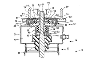
図1は車両に用いられる本実施例の車両用サスペンション装置10の平面図、図2は図1のA−A部における断面図、図3はその車両用サスペンション装置10に備えられる連結装置12の断面図であり、以下にこれらの図を参照しつつ、本実施例の車両用サスペンション装置10について説明する。車両用サスペンション装置10は、車輪に連結される車輪側部材と車体に取り付けられる車体側部材とを連結するようにして車両に設けられており、車輪と車体との接近離間動作に伴って、自身の軸線方向に伸縮可能となっている。車両用サスペンション装置10は、大まかには、車輪と車体との接近離間動作に対するばね力を発生するエアスプリング14と、その接近離間動作に対して減衰力を発生するショックアブソーバ16と、その減衰力の反力の車体側への作用を緩衝させるための連結装置12とによって構成されている。
FIG. 1 is a plan view of a
エアスプリング14は、筒状に形成されたアッパーシェル20と、そのアッパーシェル20の軸線方向において、アッパーシェル20の内部に出入可能に設けられた筒状のピストン筒22と、それらアッパーシェル20とピストン筒22とを連結するダイヤフラム24とを含んで構成されている。ダイヤフラム24は、筒状に形成されて可撓性を有しており、それの一端部がアッパーシェル20に密着されており、また、他端部がピストン筒22の上端部を覆うようにしてピストン筒22に密着されている。したがって、ピストン筒22がアッパーシェル20の内部に出入する場合であっても、ダイヤフラム24は、アッパーシェル20およびピストン筒22と密着した状態で、その出入に応じて変形することが可能となっている。また、ピストン筒22の内部には、ショックアブソーバ16の構成部品であるシリンダ26が、ピストン筒22の下端部を貫くようにして配設されている。これらピストン筒22の下端部とシリンダ26とは、隙間がないように接合されている。
The
アッパーシェル20の上端部には、中心部に穴28が設けられた環状のシェルキャップ30が固定されている。そのシェルキャップ30には、連結装置16の筐体をなすロッド保持筒32が固定される。ロッド保持筒32は、概して筒状であって、それの上方部34の内径が大きく、下方部36の内径が小さくなっており、また、外周部における高さ方向ほぼ中間部には、上方および下方を向く段差面を有する鍔部38が形成されている。ロッド保持筒32は、それの下方部36が穴28に嵌め込まれて、鍔部38の下方を向く段差面がシェルキャップ30の上面と密着するようにして配設される。さらに、鍔部38の外周部とシェルキャップ30の上面とを溶接する溶接工程が実施され、この溶接工程により、ロッド保持筒32はシェルキャップ30に固定される。このように構成される車両用サスペンション装置10において、アッパーシェル20、ピストン筒22、ダイヤフラム24、シェルキャップ30によって、ショックアブソーバ16の周囲の空間をエアチャンバ40として区画するチャンバシェル39が形成される。
An
車両用サスペンション装置10が縮む方向、つまり、車輪と車体とがバウンドする方向に相対動作すると、ピストン筒22およびシリンダ26とアッパーシェル20とが接近してチャンバシェル39内の容積が減少し、エアチャンバ40の空気圧が上昇する。一方、車両用サスペンション装置10が伸びる方向、つまり、車輪と車体とがリバウンド方向に相対動作すると、ピストン筒22およびシリンダ26とアッパーシェル20とが離間してチャンバシェル39内の容積が増加し、エアチャンバ40の空気圧が低下する。したがって、エアチャンバ40内の空気圧は、車両用サスペンション装置10の伸縮動作によって変動し、エアチャンバ40の空気圧と外部の空気圧との差に応じたばね力が発生する。つまり、車両用サスペンション装置10において、エアスプリング14はエアチャンバ40内の空気圧に依拠して車体を懸架することが可能とされているのである。
When the
ショックアブソーバ16は、それの中心軸線がチャンバシェル39の中心軸線と一致して、チャンバシェル39を貫くようにして配設されている。ショックアブソーバ16は、筒状のシリンダ26と、それの内部を軸線方向に移動可能なロッド41とを含んで構成されている。ロッド41は、シリンダ26の内部から上方へと延び出して、連結装置16を介して、後述するように車体側部材へと連結されている。また、ロッド41の上端部は、車両用サスペンション装置10の上方に位置するアクチュエータ(図示省略)に連結されている。シリンダ26の下端部には取付ブッシュ42が固定されており、その取付ブッシュ42を介して、シリンダ26は車輪を回転可能に保持する車輪保持部材に連結されている。
The
シリンダ26の内部下方には、フリーピストン43がシール部材を介してシリンダ26の軸線方向に移動可能に設置されており、フリーピストン43はシリンダ26の内部を上下二つの空間に分割している。フリーピストン43の下方の空間は、空気が充填された空気室とされており、フリーピストン43の上方の空間は、オイルが充填されたオイル室とされている。そのオイル室は、ロッド41の下端部に固定されるピストン44によって、さらに上下二つの空間に分割されている。詳しい説明は省略するが、ピストン44にはそれらの空間をつなぐ孔が設けられており、シリンダ26の内部に充填されているオイルが、その孔を介して二つの空間を往来することが可能とされている。これにより、ショックアブソーバ16は、シリンダ26とロッド41との相対動作によってオイルがピストン44の孔を通過する際に、その通過における抵抗に依拠した減衰力を発生するように構成されている。ちなみに、シリンダ26とロッド41との相対動作によるロッド41のオイル室への進入または退出によって、フリーピストン43は、空気室の空気を圧縮または膨張させて、オイルにより膨張シリンダ26の軸線方向に移動させられる。また、ショックアブソーバ16は、ロッド41の上端部に連結されるアクチュエータの作動により、その減衰力の調整を行えるように構成されている。
A
ロッド保持筒32の底面には、ゴム製のバウンドストッパ45が取り付けられている。バウンドストッパ45は、シリンダ26とロッド41とのバウンド方向の相対動作において、シリンダ26の上端部を自身に当接させることで、シリンダ26とロッド41との相対移動量を制限することが可能とされている。ちなみに、ロッド保持筒32の底面およびバウンドストッパ45には、ロッド41の直径よりも大きな直径の穴が設けられており、ロッド41はロッド保持筒32の底面およびバウンドストッパ45と接触せずに自身の軸線方向に移動することが可能とされている。
A rubber bound
ロッド41の上方部、より具体的に言えば、ロッド41のロッド保持筒32内部から上方に位置する部分の直径は、他の部分の直径よりも細くされており、それらの部分の境界には上方を向く段差面が形成されている。そのロッド41に、筒状であって上方部より下方部の内径が大きく、それらの部分の境界に下方を向く段差面が形成されているカラー46が嵌め込まれている。つまり、カラー46は、それの段差面がロッド41の段差面と向かい合う状態でロッド41に嵌め込まれているのである。
The diameter of the upper portion of the
カラー46の上方には、ゴムブッシュ48が配設されている。ゴムブッシュ48は、筒状をなしており、内周部を形成する内筒50と、外周部を形成する外筒52と、それらを連結するゴム製の弾性体54とを含んで構成とされている。内筒50は、ロッド41に嵌め込まれており、一方、外筒52は、ロッド保持筒32の下方部36に圧入されることで、ロッド保持筒32の内周面に固定されている。このように、ロッド41は、ゴムブッシュ48に保持された状態で、ロッド保持筒32に連結されている。したがって、ロッド41とロッド保持筒32とは、弾性体54の変形により、それらの軸線方向において相対変位することが許容されている。ちなみに、エアチャンバ40の空気は、ゴムブッシュ48によりエアチャンバ40と外部との連通が遮断されているため、ロッド保持筒32の内部を通って外部へと漏れることはない。
A
ゴムブッシュ48の上方であってロッド保持筒32の上方部34の内部には、環状のストッパ55がロッド41に嵌め込まれており、ストッパ55は上方部34の内周部に向かって張り出る鍔部を備えている。ストッパ55の上方には、筒状のカラー56がロッド41に嵌め込まれており、さらに、カラー56の上方には、ロッド41に成形されたねじ部にナット58が締め込まれている。したがって、カラー46、内筒50、ストッパ55、カラー56は、ナット58によって押さえつけられることで、ロッド41の外周面に固定されている。ナット58の上方には、図示を省略するアクチュエータのブラケット60がロッド41に嵌め込まれており、もう一つのナット62がロッド41のねじ部に締め込まれることで、ブラケット60はロッド41に固定されている。
An
ロッド保持筒32の上方部34について説明すると、上方部34は、それの軸線方向の高さが高くされているかしめ部64と、高さが低くされていて、後述する押え板68を支持するサポート部66とによって構成されている。かしめ部64とサポート部66とは、円周方向に等ピッチでそれぞれ三箇所ずつ交互に配置されている。また、ロッド保持筒32の外周部には、チャンバシェル39が車体に対して回転するのを許容するためのベアリング70のインナーレース72が嵌め込まれて、鍔部38の上方を向く段差面にインナーレース72の下端が支え受けられている。
The
押え板68は環状のプレートとなっており、それの中心部にロッド41およびそれに嵌め込まれたカラー56を通すための穴が設けられている。押え板68は、それの外周がロッド保持筒32の内周よりも内側にはみ出す内縁部74と、外周がロッド保持筒32の外周よりも外側にはみ出す外縁部76とによって構成されている。外縁部76は、内縁部74から外側に延び出すようにして、円周方向に等ピッチで三箇所に成形されている。
The
このように構成されるロッド保持筒32と押え板68とにおいて、押え板68がサポート部66に支持される際、押え板68は、外縁部76がサポート部66と重なるようにして配置される。この配置により、かしめ部64は内縁部74の外側から押え板68の上方へと突き出し、外縁部76はサポート部66の外側にはみ出してインナーレース72の上部に被さる。この状態で、かしめ部64を押え板68の側へと折り曲げるかしめ工程が実施されると、押え板68はロッド保持筒32の上端に固定され、また、インナーレース72は外縁部76と鍔部38の支受面とによって挟持されるのである。
In the
ベアリング70は、インナーレース72に対して相対回転することが可能なアウターレース78を有している。そのアウターレース78は、ボルト80によって車体側のマウント部に固定される取付部材である上金具82に固定されている。つまり、ベアリング70は、連結環として、内周部として機能するインナーレース72と、外周部として機能するアウターレース78と、それらの相対回転を許容する機構である複数のベアリングボール81とによって構成されている。したがって、ベアリング70によって、チャンバシェル39は車体に対する回転が許容され、チャンバシェル39の上端部に位置するシェルキャップ30は、ロッド保持筒32およびベアリング70を介して上金具82に連結されるのである。
The
車輪と車体とが接近離間する場合、ショックアブソーバ16では減衰力が発生し、その力の反力によって、ロッド41とロッド保持筒32とは、ゴムブッシュ48の弾性体54を変形させてそれらの軸線方向に相対変位させられる。そのため、弾性体54にはロッド41の軸線方向にせん断応力が発生する。さらに、車両が段差を通過する場合など、車輪と車体とが比較的大きな力によって接近離間する場合には、ロッド41とロッド保持筒32とは弾性体54を大きく変形させて相対変位する。その変位により、ロッド41とともに変位するストッパ55は、それの鍔部の外縁に設けられた環状の緩衝体であるストッパゴム84を介して押え板68またはロッド保持筒32に当接させられる。具体的に説明すると、ロッド41がロッド保持筒32に対して軸線方向上向きに変位する場合には、ストッパ55は、それと押え板68との間に位置するストッパゴム84を介して、押え板68の下面に当接し、一方、ロッド41がロッド保持筒32に対して軸線方向下向きに変位する場合には、ストッパ55は、それとロッド保持筒32との間に位置するストッパゴム84を介して、ロッド保持筒32の内壁において上方部34と下方部36との間に形成される段差面に当接する。したがって、車輪と車体とが比較的大きな力によって接近離間する場合には、これらの当接によってロッド41とロッド保持筒32との相対変位の範囲が制限されているのである。したがって、連結装置12は、弾性体54の変形量を抑えることで、弾性体54に発生するせん断力が過大となるのを防ぐことができ、弾性体54の耐久性が損なわれるのを防止することができるように構成されているのである。
When the wheel and the vehicle body approach and separate from each other, a damping force is generated in the
図3は、従来の車両用サスペンション装置100の連結装置102の断面図である。以下の車両用サスペンション装置100の説明においては、本実施例の車両用サスペンション装置10の特徴を明らかにするために必要な構成部分のみを説明し、他の構成部分についての説明は省略するものとする。車両用サスペンション装置100の有するチャンバ104の上端部には、中心部に穴106が設けられた環状のチャンバキャップ108が固定されており、穴106には、筒状をなすロッド保持筒110が嵌め込まれている。ロッド保持筒110とチャンバキャップ108とは溶接され、この溶接工程において、ロッド保持筒110とチャンバキャップ108とは、それらの間に隙間がない状態で一体とされる。チャンバキャップ108の上面には、環状であって断面がL字形をなすベアリングサポート112が溶接されており、この溶接工程により、ベアリングサポート112はチャンバキャップ108に固定される。ベアリングサポート112は、チャンバシェル39が車体に対して回転することを許容するためのベアリング70のインナーレース72を支え受けている。さらに、ベアリングサポート112の上端部が折り曲げられてインナーレース72をかしめており、そのかしめ工程により、インナーレース72はベアリングサポート112に挟持されるのである。
FIG. 3 is a cross-sectional view of the connecting
ゴムブッシュ118の外筒120は、ロッド保持筒110に圧入されることで、ロッド保持筒110の内周面に固定されている。外筒120の上端部には、リバウンド側ストッパ122が支持されており、そのリバウンド側ストッパ122は、ロッド保持筒110の上端部の折り曲げによってかしめられており、そのかしめ工程によってロッド保持筒110に固定されている。また、バウンド側ストッパ126が、リバウンド側ストッパ122の上方においてロッド124に固定されており、ショックアブソーバのロッド124とともに、ロッド保持筒110に対してそれらの軸線方向に変位できるようになっている。リバウンド側ストッパ122の上面には、環状のリバウンド側ストッパゴム128が固定されており、また、ゴムブッシュ118の内筒130の上部には、環状のバウンド側ストッパゴム132が固定されている。
The
このように構成される連結装置102において、ロッド124がロッド保持筒110に対して軸線方向上向きに変位する場合、バウンド側ストッパゴム132はリバウンド側ストッパ122の下面に当接するため、ロッド124の変位は制限される。一方、ロッド124がロッド保持筒110に対して軸線方向下向きに変位する場合、リバウンド側ストッパゴム128はバウンド側ストッパ126の下面に当接するため、ロッド124の変位は制限される。したがって、連結装置102は、ゴムブッシュ118の弾性部に発生するせん断応力が過大となるのを防ぐことができ、弾性部の耐久性が損なわれるのを防止することができるように構成されているのである。
In the connecting
このように、従来の車両用サスペンション装置100では、連結装置102の製作において、ロッド保持筒110とチャンバキャップ108との溶接、および、チャンバキャップ108とベアリングサポート112との溶接における二回の溶接工程と、ベアリングサポート112のインナーレース72へのかしめ、および、ロッド保持筒110のリバウンド側ストッパ122へのかしめにおける二回のかしめ工程とが必要とされる。本実施例の車両用サスペンション装置10では、溶接工程はロッド保持筒32の鍔部38とシェルキャップ30との溶接における一回のみ必要とされ、かしめ工程はロッド保持筒32のかしめ部64の押え板68の内縁部74へのかしめにおける一回のみ必要とされる。また、従来の車両用サスペンション装置100では、ベアリング70のインナーレース72の固定にベアリングサポート112が使用されているが、本実施例の車両用サスペンション装置10では、インナーレース72を固定するためだけに必要なベアリングサポートが設けられていない。したがって、本実施例の車両用サスペンション装置10によれば、従来の車両用サスペンション装置100と比べて、連結装置12を構成する部品点数を少なくし、かつ、それらの部品を組み立てるための工程も少なくすることができるのである。
As described above, in the conventional
図5に、本実施例の車両用サスペンション装置10に使用可能な別の連結装置140の断面図を示す。連結装置140では、押え板142のロッド保持筒144への固定に、かしめ工程ではなく、ボルト146を用いた締結による締結工程が行われている。つまり、ロッド保持筒144は、それのサポート部148にボルト146の締結のためのねじ穴が設けられており、また、押え板142にもボルト146が挿通されるための孔が設けられており、押え板142は、ボルト146がロッド保持筒144に締結されることで、ロッド保持筒144に固定されるのである。このように、押え板のロッド保持筒への固定は、かしめ工程だけではなく、締結工程や溶接工程など、様々な工程により実施され得るのである。
FIG. 5 shows a cross-sectional view of another connecting
また、本実施例の車両用サスペンション装置10は、図6に示すように、ベアリング70に代えて弾性体からなるインシュレータ160を連結環として用いることも可能である。車両用サスペンション装置10が、操舵輪である前輪側などにおいて使用される場合、チャンバシェル39が車体に対して大きく回転するため、必要な回転量を得るためにベアリング70が好適な連結環として使用され得る。一方、車両用サスペンション装置10が非転舵輪である後輪側などにおいて使用され、チャンバシェル39が車体に対して大きく回転することがない場合には、インシュレータ160により十分な回転量を得ることができる。インシュレータ160は、環状の弾性体162と、それの内周部に固着される内周部材164とを含んで構成されている。また、インシュレータ160の外周部は、車体のマウント部に固定される上金具82に固着されており、弾性体162により、内周部材164と上金具82との相対回転、つまり、弾性体162の内周部と外周部との相対回転が許容されている。ベアリング70のインナーレース72と同様に、インシュレータ160は、それの内周部材164において、外縁部76と鍔部38の支受面とによって挟持される。
Further, as shown in FIG. 6, the
したがって、本実施例の車両用サスペンション装置10によれば、インシュレータ160を用いた場合でも、従来の車両用サスペンション装置100と比べて、インシュレータ160の内周部材164の固定のみに使用する部材が必要とされないため、連結装置12を構成する部品点数を比較的少なくし、かつ、それらの部品を組み立てるための工程も比較的少なくすることができるのである。
Therefore, according to the
10:エアサスペンション装置 12:連結装置 16:ショックアブソーバ 26:シリンダ 30:シェルキャップ(上端部) 32:ロッド保持筒 38:鍔部 39:チャンバシェル 40:エアチャンバ 41:ロッド 48:ゴムブッシュ 50:内筒(内周部) 52:外筒(外周部) 54:弾性体 55:ストッパ(鍔) 68:押え板 70:ベアリング(連結環) 72:インナーレース(内周部) 74:内縁部 76:外縁部 78:アウターレース(外周部) 10: Air suspension device 12: Coupling device 16: Shock absorber 26: Cylinder 30: Shell cap (upper end) 32: Rod holding cylinder 38: Ridge part 39: Chamber shell 40: Air chamber 41: Rod 48: Rubber bushing 50: Inner cylinder (inner circumference) 52: Outer cylinder (outer circumference) 54: Elastic body 55: Stopper (ス ト ッ パ) 68: Presser plate 70: Bearing (connecting ring) 72: Inner race (inner circumference) 74: Inner edge 76 : Outer edge part 78: Outer race (outer peripheral part)
Claims (1)
そのショックアブソーバの周囲をエアチャンバとして区画するチャンバシェルを有し、そのエアチャンバ内の空気圧に依拠して車体を懸架するエアスプリングと、
前記ショックアブソーバのロッドと前記チャンバシェルの上端部を車体のマウント部に連結させるための連結装置と
を備えた車両用サスペンション装置であって、
前記連結装置が、
前記マウント部に固定的に取付けられる取付部材と、
概して筒状をなし、前記ショックアブソーバのロッドの上端部を内部に収容する状態で前記チャンバシェルの上端部に固定されたロッド保持筒と、
概して環状をなし、(a)前記取付部材に固定された外周部と、(b)前記ロッド保持筒の外周部において上方を向く段差面として形成された支受面に下端が支え受けられる状態で、そのロッド保持筒の外周部に嵌められた内周部と、(c)前記外周部と前記内周部との相対回転を許容する機構とを含んで構成され、前記チャンバシェルの車体に対する回転を許容しつつ、前記ロッド保持筒を介して前記チャンバシェルの上端部を前記取付部材に連結させるための連結環と、
概して筒状をなし、前記ロッド保持筒の内周面に外周部が固定され、前記ショックアブソーバのロッドの上端部の外周面に内周部が固定され、自身の弾性変形によって前記ロッド保持筒と前記ショックアブソーバのロッドとの軸線方向における相対変位を許容しつつ前記ロッド保持筒に前記ショックアブソーバの上端部を保持させるべく前記ロッド保持筒内部に配設されたゴムブッシュと、
そのゴムブッシュよりも上方の位置において前記ショックアブソーバのロッドの上端部に固定され、前記ロッド保持筒の内周部に向かって張り出る鍔と、
概して環状をなし、外縁部が前記ロッド保持筒の外周よりも外側にはみ出しかつ内縁部が前記ロッド保持筒の内周よりも内側にはみ出すようにして、前記ロッド保持筒の上端に固定され、前記外縁部が、前記連結環の内周部を、前記ロッド保持筒の支受面との間で挟持するとともに、前記内縁部が、前記ショックアブソーバのロッドの上端部に固定された鍔を、緩衝体を介して自身に当接させることで、前記ショックアブソーバのロッドの前記相対変位の範囲を制限するようにされた押え板と
を備えた車両用サスペンション装置。 A shock absorber disposed between the vehicle body and the wheel, having a cylinder connected to the wheel holding member and a rod extending from the cylinder, and generating a damping force for relative movement between the vehicle body and the wheel;
An air spring that has a chamber shell that divides the shock absorber as an air chamber and suspends the vehicle body depending on the air pressure in the air chamber;
A suspension device for a vehicle, comprising: a connecting device for connecting a rod of the shock absorber and an upper end portion of the chamber shell to a mount portion of a vehicle body;
The connecting device is
An attachment member fixedly attached to the mount portion;
A rod holding cylinder fixed to the upper end portion of the chamber shell in a state of generally cylindrical and containing the upper end portion of the rod of the shock absorber inside,
It is generally ring-shaped, (a) an outer peripheral portion fixed to the mounting member, and (b) a lower end supported by a support surface formed as a stepped surface facing upward at the outer peripheral portion of the rod holding cylinder. An inner peripheral portion fitted to the outer peripheral portion of the rod holding cylinder, and (c) a mechanism that allows relative rotation between the outer peripheral portion and the inner peripheral portion, and the rotation of the chamber shell relative to the vehicle body A connecting ring for connecting the upper end of the chamber shell to the mounting member via the rod holding cylinder,
It has a generally cylindrical shape, an outer peripheral portion is fixed to the inner peripheral surface of the rod holding cylinder, an inner peripheral portion is fixed to an outer peripheral surface of the upper end portion of the rod of the shock absorber, and the rod holding cylinder and A rubber bush disposed inside the rod holding cylinder to allow the rod holding cylinder to hold the upper end of the shock absorber while allowing relative displacement in the axial direction with the rod of the shock absorber;
A hook that is fixed to the upper end of the rod of the shock absorber at a position above the rubber bush, and projects toward the inner periphery of the rod holding cylinder,
It is generally ring-shaped, and is fixed to the upper end of the rod holding cylinder so that the outer edge protrudes outside the outer periphery of the rod holding cylinder and the inner edge protrudes inside the inner periphery of the rod holding cylinder, The outer edge portion sandwiches the inner peripheral portion of the connecting ring with the support surface of the rod holding cylinder, and the inner edge portion cushions the hook fixed to the upper end portion of the rod of the shock absorber. A vehicle suspension device, comprising: a presser plate configured to limit a range of the relative displacement of the rod of the shock absorber by being brought into contact with itself through a body.
Priority Applications (1)
| Application Number | Priority Date | Filing Date | Title |
|---|---|---|---|
| JP2009168158A JP2011020589A (en) | 2009-07-16 | 2009-07-16 | Vehicular suspension device |
Applications Claiming Priority (1)
| Application Number | Priority Date | Filing Date | Title |
|---|---|---|---|
| JP2009168158A JP2011020589A (en) | 2009-07-16 | 2009-07-16 | Vehicular suspension device |
Publications (1)
| Publication Number | Publication Date |
|---|---|
| JP2011020589A true JP2011020589A (en) | 2011-02-03 |
Family
ID=43631032
Family Applications (1)
| Application Number | Title | Priority Date | Filing Date |
|---|---|---|---|
| JP2009168158A Withdrawn JP2011020589A (en) | 2009-07-16 | 2009-07-16 | Vehicular suspension device |
Country Status (1)
| Country | Link |
|---|---|
| JP (1) | JP2011020589A (en) |
Cited By (3)
| Publication number | Priority date | Publication date | Assignee | Title |
|---|---|---|---|---|
| CN109017188A (en) * | 2018-10-15 | 2018-12-18 | 杨志丹 | Air spring with height detection function |
| KR20200065719A (en) * | 2018-11-30 | 2020-06-09 | (주) 영진 | Air suspension for vehicle |
| DE102012210388B4 (en) | 2011-07-19 | 2023-05-04 | Continental Automotive Technologies GmbH | air spring module |
-
2009
- 2009-07-16 JP JP2009168158A patent/JP2011020589A/en not_active Withdrawn
Cited By (5)
| Publication number | Priority date | Publication date | Assignee | Title |
|---|---|---|---|---|
| DE102012210388B4 (en) | 2011-07-19 | 2023-05-04 | Continental Automotive Technologies GmbH | air spring module |
| CN109017188A (en) * | 2018-10-15 | 2018-12-18 | 杨志丹 | Air spring with height detection function |
| CN109017188B (en) * | 2018-10-15 | 2024-03-26 | 杨志丹 | Air spring with height detection function |
| KR20200065719A (en) * | 2018-11-30 | 2020-06-09 | (주) 영진 | Air suspension for vehicle |
| KR102155661B1 (en) * | 2018-11-30 | 2020-09-14 | (주)영진 | Air suspension for vehicle |
Similar Documents
| Publication | Publication Date | Title |
|---|---|---|
| EP1681180B1 (en) | Strut mount | |
| US8191692B2 (en) | Cylinder apparatus | |
| JP5906251B2 (en) | Mounting structure for vehicle damper | |
| JP2016061425A (en) | Bump stopper cap | |
| JP5661593B2 (en) | Vehicle suspension system | |
| JP5200945B2 (en) | Car suspension equipment | |
| JP2011020589A (en) | Vehicular suspension device | |
| JP2007501729A (en) | Front strut air spring suspension system | |
| JP5050708B2 (en) | Air suspension device | |
| JP4005607B2 (en) | Strut mount | |
| JP2013117259A (en) | Vibration damping device | |
| JP2017115940A (en) | Cushion body for upper support | |
| JP2006194316A (en) | Vehicular suspension device | |
| JP2008106867A (en) | Strut mount | |
| JP2012030610A (en) | Suspension device | |
| JP2005090600A (en) | Vibration control device | |
| JP2001311444A (en) | Hydraulic shock absorber | |
| JP6863221B2 (en) | Suspension device | |
| JP7389447B2 (en) | hydraulic shock absorber | |
| JP2005248972A (en) | Suspension device | |
| JP2006264425A (en) | Upper support for suspension, and suspension device for automobile using the same | |
| US20230144133A1 (en) | Mounting assembly for fixing a component of a vehicle brake system to a vehicle structure and vehicle | |
| JP2010276137A (en) | Strut mount | |
| JP6863222B2 (en) | Suspension device | |
| JP2014228024A (en) | Stopper |
Legal Events
| Date | Code | Title | Description |
|---|---|---|---|
| A300 | Withdrawal of application because of no request for examination |
Free format text: JAPANESE INTERMEDIATE CODE: A300 Effective date: 20121002 |