EP4177112A1 - Vehicle article carrier rack system with stowable, concealable cross bars - Google Patents
Vehicle article carrier rack system with stowable, concealable cross bars Download PDFInfo
- Publication number
- EP4177112A1 EP4177112A1 EP22186985.2A EP22186985A EP4177112A1 EP 4177112 A1 EP4177112 A1 EP 4177112A1 EP 22186985 A EP22186985 A EP 22186985A EP 4177112 A1 EP4177112 A1 EP 4177112A1
- Authority
- EP
- European Patent Office
- Prior art keywords
- cross bar
- support rail
- assembly
- assemblies
- vehicle
- Prior art date
- Legal status (The legal status is an assumption and is not a legal conclusion. Google has not performed a legal analysis and makes no representation as to the accuracy of the status listed.)
- Pending
Links
- 230000000712 assembly Effects 0.000 claims abstract description 77
- 238000000429 assembly Methods 0.000 claims abstract description 77
- 238000010276 construction Methods 0.000 abstract description 24
- 238000000034 method Methods 0.000 description 6
- 230000008901 benefit Effects 0.000 description 5
- XAGFODPZIPBFFR-UHFFFAOYSA-N aluminium Chemical compound [Al] XAGFODPZIPBFFR-UHFFFAOYSA-N 0.000 description 3
- 229910052782 aluminium Inorganic materials 0.000 description 3
- 229910000831 Steel Inorganic materials 0.000 description 2
- 239000000969 carrier Substances 0.000 description 2
- 239000000463 material Substances 0.000 description 2
- 230000004048 modification Effects 0.000 description 2
- 238000012986 modification Methods 0.000 description 2
- 239000004033 plastic Substances 0.000 description 2
- 229920003023 plastic Polymers 0.000 description 2
- 239000010959 steel Substances 0.000 description 2
- 239000000853 adhesive Substances 0.000 description 1
- 230000001070 adhesive effect Effects 0.000 description 1
- 230000009286 beneficial effect Effects 0.000 description 1
- 238000005516 engineering process Methods 0.000 description 1
- 230000002708 enhancing effect Effects 0.000 description 1
- 239000000446 fuel Substances 0.000 description 1
- 238000004519 manufacturing process Methods 0.000 description 1
Images


Classifications
-
- B—PERFORMING OPERATIONS; TRANSPORTING
- B60—VEHICLES IN GENERAL
- B60R—VEHICLES, VEHICLE FITTINGS, OR VEHICLE PARTS, NOT OTHERWISE PROVIDED FOR
- B60R9/00—Supplementary fittings on vehicle exterior for carrying loads, e.g. luggage, sports gear or the like
- B60R9/04—Carriers associated with vehicle roof
- B60R9/045—Carriers being adjustable or transformable, e.g. expansible, collapsible
-
- B—PERFORMING OPERATIONS; TRANSPORTING
- B60—VEHICLES IN GENERAL
- B60R—VEHICLES, VEHICLE FITTINGS, OR VEHICLE PARTS, NOT OTHERWISE PROVIDED FOR
- B60R9/00—Supplementary fittings on vehicle exterior for carrying loads, e.g. luggage, sports gear or the like
- B60R9/08—Supplementary fittings on vehicle exterior for carrying loads, e.g. luggage, sports gear or the like specially adapted for sports gear
Definitions
- the present disclosure relates to vehicle article carrier systems, and more particularly to a vehicle article carrier system having a construction which enables a pair of cross bars of the system to be secured in both operative and stowed positions, and when placed in their stowed positions during periods of non-use the cross bars are generally not visible from the sides of the vehicle.
- Article carriers have been used on various types of passenger motor vehicles, especially sedans, station wagons, SUVs and pickup trucks, for a number of years, and are viewed by many as being indispensable for carrying a wide variety of articles that would be difficult, impractical, inconvenient or impossible to carry within the passenger compartment of the vehicle.
- vehicle article carriers include a pair of side rails which are fixedly secured to a roof portion of the vehicle, with a pair of cross bars that extend between the support rails.
- Articles of widely varying shapes and sizes can be secured to the cross bars and thus supported above the outer body roof surface of the vehicle.
- the cross bars are also often used to secure other implements, such as ski racks, bicycle racks, etc., which enable a wide variety of recreational items to be easily supported using the cross bars.
- stowable it is meant cross bars which are able to be fixedly secured in non-operative positions extending parallel to the support rails, or parallel to separate forward and rearward pairs of support feet, rather than perpendicularly between the support rails, or perpendicularly between pairs of the support feet.
- the ability to store the cross bars parallel to the support rails, or parallel to the support feet can significantly reduce wind resistance and sometimes even wind noise, making the vehicle article carrier system more aerodynamically efficient during those times where the vehicle is being used but the cross bars are not needed to support any articles thereon.
- Some vehicle article carrier systems developed by the assignee of the present disclosure are known in the industry as "swing-in-place" systems, because one end of each of one the pair of cross bars is pivotally secured at one end to a respective one of the forward or rearward support feet, while the opposite end is free to pivot between a stowed position extending between a forward pair of support feet, or between a rearward pair of the support feet.
- each cross bar is secured at its opposite ends to one pair of forward and rearward mounted support feet, and as such they form the appearance of a support rail, or otherwise they may sit above a respective decorative support rail that extends between the forward and rearward support feet.
- a new vehicle article carrier system which provides the benefits of traditional swing-in-place and stowable vehicle article carrier systems, which provides the benefit of completely hiding the cross bars from view when they are stowed, would be highly desirable, not just from an aesthetic standpoint, but from a fuel efficiency standpoint as well.
- the present disclosure relates to a vehicle article carrier system for carrying articles elevationally above an outer body surface of a vehicle.
- the system may comprise first and second support rail assemblies fixed supported on an outer body roof surface parallel to one another and parallel, with the first support rail being secured adjacent a first side of the vehicle, and the second support rail being secured adjacent a second side of the vehicle.
- the system may also include a first cross bar configured to be secured in a stowed position on the first support rail assembly, and in an operative position extending parallel between the first and second support rail assemblies and secured to the first and second support rail assemblies.
- the system may also include a second cross bar configured to be secured in a stowed position on the second support rail assembly, and in an operative position extending perpendicularly between the first and second support rail assemblies and secured to the first and second support rail assemblies.
- Each of the first and support rail assemblies include a main rail portion having an L-shape when viewed endwise.
- the L-shape has a vertical wall portion and a horizontal shelf portion.
- the vertical wall portion has a height generally equal to an upper surface of its associated said first or second cross bar when its associated said first or second cross bar is positioned in the stowed position, to thus hide said first or second cross bar.
- the first cross bar when in the stowed position, is not visible when viewing the first support rail from the first side of the vehicle, and the second cross bar is not visible, when in the stowed position, when viewing the second support rail assembly from the second side of the vehicle.
- the present disclosure relates to a vehicle article carrier system for carrying articles elevationally above an outer body surface of a vehicle.
- the system may comprise first and second support rail assemblies fixed supported on an outer body roof surface parallel to one another.
- the first support rail is secured adjacent a first side of the vehicle, and the second support rail is secured adjacent a second side of the vehicle.
- a front cross bar is included which is configured to be secured in a stowed position on the first support rail assembly, and in an operative position extending parallel between the first and second support rail assemblies while being secured to the first and second support rail assemblies.
- a rear cross bar is included which is configured to be secured in a stowed position on the second support rail assembly, and in an operative position extending perpendicularly between the first and second support rail assemblies while being secured to the first and second support rail assemblies.
- Each of the first and support rail assemblies includes a main rail portion having an L-shape when viewed endwise.
- the L-shape has a vertical wall portion and a horizontal shelf portion.
- the vertical wall portion has a height generally equal to an upper surface of its associated said front or rear cross bar when its associated said front or rear cross bar is positioned in the stowed position, such that the front cross bar rests behind the vertical wall portion of said first support rail assembly when placed in the stowed position.
- first and second support rail assemblies cooperatively define first and second spaced apart mounting locations at which the rear cross bar can be secured when positioned in its operative position.
- the present disclosure relates to a vehicle article carrier system for carrying articles elevationally above an outer body surface of a vehicle.
- the system may comprise first and second support rail assemblies fixed supported on an outer body roof surface parallel to one another.
- the first support rail being secured adjacent a first side of the vehicle
- the second support rail being secured adjacent a second side of the vehicle.
- a front cross bar is included which is configured to be secured in a stowed position on the first support rail assembly, and in an operative position extending parallel between the first and second support rail assemblies while being secured at its opposing ends to the first and second support rail assemblies.
- a rear cross bar is included which is configured to be secured in a stowed position on the second support rail assembly, and in an operative position extending perpendicularly between the first and second support rail assemblies while being secured at its opposing ends to the first and second support rail assemblies.
- Each of the first and support rail assemblies includes a main rail portion having an L-shape when viewed endwise.
- the L-shape has a vertical wall portion and a horizontal shelf portion.
- the vertical wall portion has a height generally equal to an upper surface of its associated front or rear cross bar when its associated front or rear cross bar is positioned in the stowed position, such that the front cross bar rests behind the vertical wall portion of said first support rail assembly when placed in the stowed position, and the rear cross bar rests behind the vertical wall portion of the second support rail assembly when placed in the stowed position.
- the horizontal shelf portion of the first support rail assembly has a length approximately equal to a width of the first cross bar
- the horizontal shelf portion of the second support rail assembly has a width approximately equal to a width of the second cross bar.
- the horizontal shelf portions are also positioned in a common horizontal plane.
- the system 10 includes a pair of support rails assemblies 12a and 12b which are fixedly secured to an outer body roof surface 14 of a motor vehicle 16.
- the support rail assembly 12a is fixedly secured along a longitudinal length of the outer body vehicle roof surface 14 adjacent the driver's side of the vehicle 16, while the support rail assembly 12b is similarly secured adjacent the passenger side of the vehicle.
- Each support rail assembly 12a and 12b includes a main rail portion 18a or 18b supported between a front support foot assembly 20a or 20b, and a rear support foot assembly 22a or 22b.
- a front cross bar assembly 24a may be pivotally secured at one end and latched at its opposite end to the support rail assembly 12a to place it in a stowed position over the main rail portion 18a.
- a rear cross bar assembly 24b may be pivotally secured at one end to the support rail assembly 12b, and latched at its opposite end to the support rail assembly 12b, to place it in a stowed position over the main rail portion 18b.
- the lengths of the cross bar assemblies 24a and 24b are tailored such that they can be stowed on their respective support rails assemblies 12a and 12b, and when positioned perpendicularly in their operative positions, the support rail assemblies 12a and 12b are perfectly located, width-wise, on the outer body vehicle roof surface 14 to enable attachment of the free ends of the cross bar assemblies to opposite ones of the support rail assemblies 12a or 12b.
- each rail main portion 18a and 18b is its generally L-shaped construction, when viewed in cross section, as shown in Figure 5 . This feature will be discussed in greater detail in the following paragraphs.
- the L-shaped cross-sectional construction enables each of the cross bar assemblies 24a and 24b to rest within the L-shaped configuration of their associated support rails 12a and 12b, respectively, and be completely hidden from view, or virtually completely hidden from view, when a person stands along the driver's side or the passenger side of the vehicle 16 and looks at the system 10.
- cross bar assembly 24a and 24b are both compactly housed on their respective main rail portions 18a and 18b when mounted in their stowed positions. And even as shown in Figure 4 , when viewing the inside of the support rail assembly 12b, the cross bar assembly 24b has the general appearance of being an integrally formed portion of the support rail assembly 12b.
- the L-shaped cross-sectional construction of the main rail portion 18b can be seen.
- the main rail portion 18a has this same cross-sectional shape, and will appear as a mirror image of the main rail portion 18b when the two support rail assemblies 12a and 12b are installed on the vehicle outer body roof surface 14.
- the rail main portion 18b has a horizontal shelf portion 18' and a vertical wall portion 18".
- the vertical wall portion 18" is about equal (i.e., level with) the upper surface of the cross bar assembly 24b, as indicated by arrow "H"
- the horizontal shelf portion 18' is about equal in length to a cross-sectional width of the cross bar assembly 24b, as indicated by arrow "L".
- the cross bar assembly 24b can be generally concealed from view when standing along the passenger side of the vehicle 16 because it does not extend above the upper edge of the vertical wall portion 18". Nor does the cross bar assembly 24 extend beyond an inward edge of the horizontal shelf portion 18' when mounted in its stowed position. This further helps to provide a clean, aesthetically pleasing appearance to the rack system 10 when it is viewed from the front or rear while the cross bar assemblies 24a and 24b are both mounted in their stowed positions.
- Still another advantage is that the horizontal shelf portions 18' of the support rail assemblies 12a and 12b lie within a common horizontal plane, which enables both of the cross bar assemblies 24a and 24b be positioned level when they are in their operative positions (assuming the vehicle 16 is on level ground), and both to be positioned at the same vertical height when positioned in their stowed positions on their respective support rail assembly 12a or 12b. This further helps to create a highly aesthetically pleasing appearance whether the cross bar assemblies 24a and 24b are secured in their operative or stowed positions.
- the ability to stow the cross bar assemblies 24a and 24b on their respective main rail portions 18a and 18b, respectively, without the cross bar assemblies projecting above the main rail portions 18, or inwardly beyond the inner edges of the main rail portions 18a and 18b, also helps to significantly reduce the aerodynamic drag imposed by the system 10 while the vehicle 16 is travelling at intermediate or highway speeds, and potentially helps to eliminate, or substantially reduce, any wind noise that might be encountered when the vehicle is operated with the cross bar assemblies 24a and 24b mounted in their stowed positions.
- the stowed cross bars 24a and 24b appear to be integral portions of the main support rail assemblies 12a and 12b when mounted in their stowed positions, and thus make for a very aesthetically clean looking and highly aerodynamic configuration.
- the support rail assembly 12a of Figure 6 includes the main rail portion 18a which telescopically engages with structural mounting portions 26a and 28a of the front and rear support foot assemblies 22a and 22b, respectively.
- the front and rear structural mounting portions 26a and 28a may be of aluminum die cast construction or otherwise made from similarly robust construction techniques and materials (e.g., high strength plastics).
- the structural mounting portions 26a and 28a are attached to the outer body roof surface 14 of the vehicle 16 and telescopically receive the opposing ends of the main rail portion 18a.
- a front lower cover element 30a and a rear lower cover element 32a (e.g., both made from plastic), as well as front and rear mounting pads 34a and 36a, are interposed between the structural mounting portions and the outer body roof surface 14.
- Conventional threaded fasteners (or a combination of threaded fasteners and suitable adhesives) may be used to secure the structural mounting portions 26a and 28a to the outer body roof surface 14.
- Decorative front and rear cover portions 38a and 40a may also be secured over the front and rear structural mounting portions 26a and 28a, respectively.
- a center support assembly comprised of components structural mounting portions 46a, 48a and 50a may be interconnected using conventional threaded fasteners to secure a midpoint of the main rail portion 18a to the vehicle outer body roof surface 14 to provide added support and rigidity to the main rail portion 18a.
- the cross bar assembly 24a includes a first end having a pivot assembly 52 and a second end having a manually actuatable latching assembly 54.
- the pivot assembly 52 is coupled to a mounting surface 56 on the front structural mounting portion 28a.
- the latching assembly 54 may be engaged with an opening 58 in the main rail portion 18a to hold the cross bar assembly 24a in the stowed position on the main rail portion 18a, when not in use.
- the latching assembly 54 passes through an opening 60 ( Figure 7 ) in the main rail portion 18b and into engagement with a portion of a front structural mounting portion 26b of the support rail assembly 12b. This places the front cross bar assembly 24a in its operative position extending perpendicularly between the two support rail assemblies 12a and 12b.
- the support rail assembly 12b is similar in construction to the support rail assembly 12a, and components in common will be designated with the same reference number used to describe the support rail assembly 12a but with a "b" suffix.
- the support rail assembly 12a further includes a mounting element 62 fixedly secured by conventional threaded fasteners within the main rail portion 18a, and accessible through an opening 76 formed in the main rail portion.
- the main rail portion 18b includes a channel 64 formed along a portion of its length, and generally in the rear half of the length thereof. The channel 64 is also shown in Figure 10 .
- a slidable securing element in this example a slide block 66, with an associated elastomeric O-ring 67 and a threaded fastener plate 68, are all positioned inside the main rail portion 18b, and coupled to a pivot assembly 70 associated with a first (i.e., pivoting) end of the rear cross bar assembly 24b, which enables pivoting of the rear cross bar assembly 24b between the stowed position, wherein it is arranged parallel to the main rail portion 18b, and its operative position wherein it extends perpendicularly between the rear support foot assemblies 22a and 22b.
- the pivot assembly 70 may each be constructed in accordance with the teachings of one or more of the above referenced U.S. Patents, which enables a small degree of pivotal motion within a vertical plane, as well as the needed pivoting motion within a horizontal plane, to enable lifting the cross bar 24a or 24b vertically a small degree while repositioning the cross bar assembly 24a or 24b to one or the other of the support rail assemblies 12a or 12b.
- the O-ring 67 provides the beneficial feature of providing a small degree of resilience in the attachment of the cross bar 24a or 24b which allows its associated cross bar to be lifted vertically a small amount, while still permitting pivoting motion in the horizontal plane, and while still enabling a sufficiently secure attachment of the pivoting end of each cross bar assembly to prevent any rattling during use of the vehicle 16.
- the opposite end of the rear cross bar assembly 24b includes a user engageable latching assembly 72 which may be identical in construction to the latching assembly 54.
- the rear cross bar assembly 24b has three possible mounting positions, one being a stowed position on its associated main rail portion 18b, a second being a rearward most operative position, and the third being an intermediate position closer to the front of the vehicle 16. These two rearward mounting positions are shown in Figure 2 , with it being understood one or the other, but not both, will be used at any given time. This provides significant added flexibility in carrying articles of widely varying dimensions.
- the pivot assembly 70 can be secured at either extreme end of the channel 64, to thus help hold the rear cross bar assembly 24b in any one of the above three described positions, by simply tightening a threaded element 71 ( Figure 7 ) that extends therethrough and engages the threaded fastener plate 68.
- latching assemblies 54 and 72 are well known in the art. These types of user engageable latching assemblies, for example, are disclosed in U.S. Patents Nos. 6,811,066 and 7,066,364 , assigned to the assignee of the present disclosure. Suitable pivot assemblies for use with a cross bar are also disclosed in these patents. Furthermore, it will be appreciated that the various components shown in Figure 7 and denoted with reference numbers having the suffix "b" are the counterparts to those described above and shown in Figure 6 .
- FIG 8 a plan view of a rear portion of the main rail portion 18a is shown with the mounting element 62 fixedly secured within the main rail portion.
- the rear structural mounting portion 28a includes an integrally secured mounting element 74, as also shown in Figure 9 , which is inserted within the main rail portion 18a when the rear structural mounting portion 28a is assembled to the main rail portion 18a during assembly of the support rail assembly 12a.
- the main rail portion 18a includes the generally circular opening 76 and an additional generally circular opening 78, which each expose their respective mounting elements 62 and 74. This enables the latching assembly 54 of the rear cross bar assembly 24b to engage either one of the mounting elements 62 or 74, depending on which of the two rearward locations it is being mounted at. And as noted above, the latching assembly 54 of the front cross bar assembly 24a engages the mounting element 74 when it is positioned in its stowed position on the support rail assembly 12a.
- the channel 64 in the main rail portion 18b forms a track which can be seen better along with the slide block 66 positioned therein.
- the slide block 66 is shown in both of its potential rearward mounting positions, although it will be appreciated that in actual use of the system 10 there is only one slide block 66 being used.
- the slide block 66 is held at a specific position by tightening of the threaded external fastener element 71 to the fastener plate 68.
- This construction secures the pivot assembly 70 to the main rail portion 18b while still allowing both pivoting motion of the rear cross bar assembly 24b, as well as linear sliding movement of the pivot assembly 70, at one end of the rear cross bar assembly 24b.
- the rear cross bar assembly 24b' in Figure 11 has a pivot assembly 70' construction which incorporates a threaded element 71' which extends therethrough and which engages a suitable threaded plate or element (not shown in Figure 11 ) fixedly mounted within the support rail assembly 12b'.
- a suitable threaded plate or element (not shown in Figure 11 ) fixedly mounted within the support rail assembly 12b'.
- manual removal of the threaded element 71' enables the pivot assembly 70' to be completely lifted off of its associated support rail assembly 12b' and moved to a more forward position on the support rail assembly 12b' and then re-secured thereto using the same threaded element 71'.
- This configuration also allows the rear cross bar 24b' to be pivoted into its operative position, when mounted as shown in Figure 11 , by simply rotating the cross bar assembly 24b' perpendicularly until the opposite end is positioned over the other support rail assembly 12a.
- Figure 11 shows another feature that may be incorporated into the system 10 which prevents the rear cross bar assembly 24b' from falling on the outer body roof surface 14 if the user accidentally loses his/her grip on the assembly 24b' while moving the rear cross bar assembly from its stowed position into its operative position, or from its operative position into its stowed position.
- a rear support foot 22b' includes a circumferential ramp portion 84' projecting up from an upper surface 86' thereof.
- the ramp portion 84' cooperates with the lower surface 82' by contacting the lower surface 82' to prevent the cross bar assembly 24b' from dropping down onto the outer body roof surface 14 of the vehicle 16 if the user should accidentally release the cross bar assembly 24b' before the latching assembly 72 at its opposite end is positioned over the support rail assembly 12a. In such an instance, the latching assembly 72 will be held above the outer body roof surface 14 by contact with the ramp portion 84'.
- This feature also enables shorter individuals who may not be able to maneuver the cross bar assembly 24b easily into its fully perpendicular extending position to initiate the process from one side of the vehicle 16 by moving the rear cross bar assembly to an intermediate position over the outer body roof surface 14, and then going to the other side of the vehicle to reach up and pull the opposite end of the rear cross bar assembly 24b into its fully perpendicular position for attachment to the support rail assembly 12a. It will be appreciated that this feature may be incorporated into the front support foot 20a as well if desired.
- FIG. 12 a swing-in-place vehicle article carrier system 100 in accordance with another embodiment of the present disclosure is shown.
- the system 100 is similar in operation to the system 10, but instead of a multi-piece support rail construction as used for the support rail assemblies 12a and 12b, which requires the structural mounting portions 26a and 28a, the system 100 makes use of one piece support rail assemblies 102a and 102b.
- This construction dramatically reduces the construction complexity of the support rail assemblies 102a and 102b, while providing even further enhanced structural capability due to its single piece construction.
- Support rail assembly 102a houses a front cross bar assembly 104a
- support rail assembly 102b houses a rear cross bar assembly 104b.
- the front cross bar assembly 104a has a first end with a pivot assembly 106a which provides for pivotal movement of the cross bar assembly 104a between it stowed position and its operative position, while the opposite end includes a latching assembly 108a which allows the front cross bar assembly to be secured in its operative position, or as well as in its stowed position.
- the rear cross bar assembly 104b similarly includes a pivot assembly 108b located at its rear end, and a latching assembly 106a located at its front end, enabling the rear cross bar assembly to be pivoted and secured in either one of two different operative positions near a rear area of the support rail assemblies 102a and 102b.
- the rear cross bar assembly 104b is fully removable to enable the rearward mounting at two different positions, as described above with respect to Figure 10 .
- the system 100 provides the same benefits as the system 10 in that the cross bar assemblies 104a and 104b are hidden from view when placed in their stowed positions, and when an individual is viewing the vehicle 16 from most angles around the perimeter of the vehicle.
- FIG. 13 an exploded perspective view of the components of the support rail assembly 102b are shown to illustrate the dramatically reduced number of individual component parts which make up its construction.
- the support rail assembly 102a may be of nearly identical construction, with the principal differences being the positioning of the components which engage with the latching assemblies 108a to enable the cross bar assemblies 104a and 104b to be placed in their stowed and operative positions.
- the main rail portion 110b has a central portion 112b having the L-shaped cross-sectional construction described herein for the support rail assemblies 12a and 12b, but also includes an integrally formed curving front, portion 114b at one end, and an integrally formed curving rear portion 116b at its other end.
- a front structural mounting block 118 (e.g., die-cast aluminum or steel) with integrated threaded fasteners is secured to the curving front portion 114b of the main rail portion 110b and to a decorative lower/outer cover member 120 by using threaded fasteners 122.
- the decorative lower/outer cover has a shape and profile to fit under the curving front portion 114b of the main rail portion 110b.
- a separate plurality of threaded screws 124 is used to secure a decorative upper cover member 126 to the lower/outer cover member 120 such that the curving front portion 114b is partially encapsulated between the two decorative cover members 120 and 126.
- a resilient pad 128 is placed directly against the outer body roof surface 14, and lower areas of the two decorative cover members 120 and 126 rest against the pad 128, which serves to take up any gaps between the decorative cover members 120/126 and the outer body roof surface 14.
- a similar construction is present at the curving rear portion 116b of the main rail portion 110b, where a structural mounting block 130 with integrated threaded fasteners is secured to the curving rear portion 116b, and to a decorative rear lower cover member 132, via threaded fasteners 134.
- a decorative rear upper/inner cover member 136 is secured to the decorative rear lower cover member 132 via a separate plurality of threaded fasteners 138, which partially encapsulates the rear portion 116b of the main rail portion 110b.
- a resilient pad 140 is placed between the outer body roof surface 14 and the decorative rear cover members 132/136 to help take up any gaps between these components and the outer body roof surface.
- This configuration enables the curving front and rear portions 114b and 116b of the main rail portion 110b to be directly secured to the vehicle outer body surface 14, which allows forces experienced by the main rail portion 110b to be transferred directly into the outer body surface 14 rather than into an intermediate component.
- This construction not only significantly enhances the strength of the main rail portion 110b, but also significantly enhances its overall rigidity as well.
- the reduced number of independent component parts also reduces costs and enables even quicker and easier assembly of the support rail assembly 102b on the vehicle 16.
- a front cross bar mounting element 142 is fixedly secured with threaded fasteners 144 to the main rail portion, which provides the point of attachment for the latching assembly 108a of the front cross bar assembly 104a when the front cross bar assembly is secured in its operative position.
- a pair of rear cross bar mounting elements 146 and 148 are secured to the main rail portion 110b via pairs of threaded fasteners 150 and 152, respectively.
- the rear cross bar mounting elements 146 and 148 define the two operative positions for the rear cross bar assembly 104b, while the rearward most cross bar mounting element 146 also operates to provide an attachment point for the rear cross bar assembly 104b when it is secured in its stowed position over the support rail assembly 102b.
- Example embodiments are provided so that this disclosure will be thorough, and will fully convey the scope to those who are skilled in the art. Numerous specific details are set forth such as examples of specific components, devices, and methods, to provide a thorough understanding of embodiments of the present disclosure. It will be apparent to those skilled in the art that specific details need not be employed, that example embodiments may be embodied in many different forms and that neither should be construed to limit the scope of the disclosure. In some example embodiments, well-known processes, well-known device structures, and well-known technologies are not described in detail.
- first, second, third, etc. may be used herein to describe various elements, components, regions, layers and/or sections, these elements, components, regions, layers and/or sections should not be limited by these terms. These terms may be only used to distinguish one element, component, region, layer or section from another region, layer or section. Terms such as “first,” “second,” and other numerical terms when used herein do not imply a sequence or order unless clearly indicated by the context. Thus, a first element, component, region, layer or section discussed below could be termed a second element, component, region, layer or section without departing from the teachings of the example embodiments.
- spatially relative terms such as “inner,” “outer,” “beneath,” “below,” “lower,” “above,” “upper,” and the like, may be used herein for ease of description to describe one element or feature's relationship to another element(s) or feature(s) as illustrated in the figures.
- Spatially relative terms may be intended to encompass different orientations of the device in use or operation in addition to the orientation depicted in the figures. For example, if the device in the figures is turned over, elements described as “below” or “beneath” other elements or features would then be oriented “above” the other elements or features.
- the example term “below” can encompass both an orientation of above and below.
- the device may be otherwise oriented (rotated 90 degrees or at other orientations) and the spatially relative descriptors used herein interpreted accordingly.
Abstract
Description
- The present disclosure relates to vehicle article carrier systems, and more particularly to a vehicle article carrier system having a construction which enables a pair of cross bars of the system to be secured in both operative and stowed positions, and when placed in their stowed positions during periods of non-use the cross bars are generally not visible from the sides of the vehicle.
- The statements in this section merely provide background information related to the present disclosure and may not constitute prior art.
- Article carriers have been used on various types of passenger motor vehicles, especially sedans, station wagons, SUVs and pickup trucks, for a number of years, and are viewed by many as being indispensable for carrying a wide variety of articles that would be difficult, impractical, inconvenient or impossible to carry within the passenger compartment of the vehicle. Typically such vehicle article carriers include a pair of side rails which are fixedly secured to a roof portion of the vehicle, with a pair of cross bars that extend between the support rails. Articles of widely varying shapes and sizes can be secured to the cross bars and thus supported above the outer body roof surface of the vehicle. The cross bars are also often used to secure other implements, such as ski racks, bicycle racks, etc., which enable a wide variety of recreational items to be easily supported using the cross bars.
- The assignee of the present disclosure is a leader in manufacturing vehicle article carrier systems such as described above, and has also pioneered the development of vehicle article carrier systems that have stowable cross bars. By "stowable" it is meant cross bars which are able to be fixedly secured in non-operative positions extending parallel to the support rails, or parallel to separate forward and rearward pairs of support feet, rather than perpendicularly between the support rails, or perpendicularly between pairs of the support feet. In either instance, the ability to store the cross bars parallel to the support rails, or parallel to the support feet, can significantly reduce wind resistance and sometimes even wind noise, making the vehicle article carrier system more aerodynamically efficient during those times where the vehicle is being used but the cross bars are not needed to support any articles thereon.
- Some vehicle article carrier systems developed by the assignee of the present disclosure are known in the industry as "swing-in-place" systems, because one end of each of one the pair of cross bars is pivotally secured at one end to a respective one of the forward or rearward support feet, while the opposite end is free to pivot between a stowed position extending between a forward pair of support feet, or between a rearward pair of the support feet. When the cross bars are not needed, each cross bar is secured at its opposite ends to one pair of forward and rearward mounted support feet, and as such they form the appearance of a support rail, or otherwise they may sit above a respective decorative support rail that extends between the forward and rearward support feet. But in both of these stowed positions, the cross bars typically are visible from the side of the vehicle.
U.S. Patent Nos. 5,511709 ,6,811,066 ,7,066,364 ,7,090,103 ,7,448,523 ,8,028,875 ,8,235,264 ,8,251,267 ,8,096,454 ,8,276,794 ,8,528,799 , andU.S. Patent Publication No. 2016/0243994 , are all owned by the assignee of the present disclosure, and all show various forms of stowable rack systems, or swing-in-place rack systems, or components that may be used therewith, and are all hereby incorporated by reference into the present disclosure. - There is a growing interest in enhancing the smooth, flowing, aerodynamic appearance of the support rails of a vehicle article carrier system, while still maintaining the significant practical benefits that swing-in-place and stowable vehicle article carrier systems provide with respect to the stowed positioning of the cross bars. A new vehicle article carrier system which provides the benefits of traditional swing-in-place and stowable vehicle article carrier systems, which provides the benefit of completely hiding the cross bars from view when they are stowed, would be highly desirable, not just from an aesthetic standpoint, but from a fuel efficiency standpoint as well.
- This section provides a general summary of the disclosure, and is not a comprehensive disclosure of its full scope or all of its features.
- In one aspect the present disclosure relates to a vehicle article carrier system for carrying articles elevationally above an outer body surface of a vehicle. The system may comprise first and second support rail assemblies fixed supported on an outer body roof surface parallel to one another and parallel, with the first support rail being secured adjacent a first side of the vehicle, and the second support rail being secured adjacent a second side of the vehicle. The system may also include a first cross bar configured to be secured in a stowed position on the first support rail assembly, and in an operative position extending parallel between the first and second support rail assemblies and secured to the first and second support rail assemblies. The system may also include a second cross bar configured to be secured in a stowed position on the second support rail assembly, and in an operative position extending perpendicularly between the first and second support rail assemblies and secured to the first and second support rail assemblies. Each of the first and support rail assemblies include a main rail portion having an L-shape when viewed endwise. The L-shape has a vertical wall portion and a horizontal shelf portion. The vertical wall portion has a height generally equal to an upper surface of its associated said first or second cross bar when its associated said first or second cross bar is positioned in the stowed position, to thus hide said first or second cross bar. Thus, the first cross bar, when in the stowed position, is not visible when viewing the first support rail from the first side of the vehicle, and the second cross bar is not visible, when in the stowed position, when viewing the second support rail assembly from the second side of the vehicle.
- In another aspect the present disclosure relates to a vehicle article carrier system for carrying articles elevationally above an outer body surface of a vehicle. The system may comprise first and second support rail assemblies fixed supported on an outer body roof surface parallel to one another. The first support rail is secured adjacent a first side of the vehicle, and the second support rail is secured adjacent a second side of the vehicle. A front cross bar is included which is configured to be secured in a stowed position on the first support rail assembly, and in an operative position extending parallel between the first and second support rail assemblies while being secured to the first and second support rail assemblies. A rear cross bar is included which is configured to be secured in a stowed position on the second support rail assembly, and in an operative position extending perpendicularly between the first and second support rail assemblies while being secured to the first and second support rail assemblies. Each of the first and support rail assemblies includes a main rail portion having an L-shape when viewed endwise. The L-shape has a vertical wall portion and a horizontal shelf portion. The vertical wall portion has a height generally equal to an upper surface of its associated said front or rear cross bar when its associated said front or rear cross bar is positioned in the stowed position, such that the front cross bar rests behind the vertical wall portion of said first support rail assembly when placed in the stowed position. Similarly, the rear cross bar rests behind the vertical wall portion of the second support rail assembly when placed in the stowed position. The first and second support rail assemblies cooperatively define first and second spaced apart mounting locations at which the rear cross bar can be secured when positioned in its operative position.
- In still another aspect the present disclosure relates to a vehicle article carrier system for carrying articles elevationally above an outer body surface of a vehicle. The system may comprise first and second support rail assemblies fixed supported on an outer body roof surface parallel to one another. The first support rail being secured adjacent a first side of the vehicle, and the second support rail being secured adjacent a second side of the vehicle. A front cross bar is included which is configured to be secured in a stowed position on the first support rail assembly, and in an operative position extending parallel between the first and second support rail assemblies while being secured at its opposing ends to the first and second support rail assemblies. A rear cross bar is included which is configured to be secured in a stowed position on the second support rail assembly, and in an operative position extending perpendicularly between the first and second support rail assemblies while being secured at its opposing ends to the first and second support rail assemblies. Each of the first and support rail assemblies includes a main rail portion having an L-shape when viewed endwise. The L-shape has a vertical wall portion and a horizontal shelf portion. The vertical wall portion has a height generally equal to an upper surface of its associated front or rear cross bar when its associated front or rear cross bar is positioned in the stowed position, such that the front cross bar rests behind the vertical wall portion of said first support rail assembly when placed in the stowed position, and the rear cross bar rests behind the vertical wall portion of the second support rail assembly when placed in the stowed position. The horizontal shelf portion of the first support rail assembly has a length approximately equal to a width of the first cross bar, and the horizontal shelf portion of the second support rail assembly has a width approximately equal to a width of the second cross bar. The horizontal shelf portions are also positioned in a common horizontal plane.
- Further areas of applicability will become apparent from the description provided herein. It should be understood that the description and specific examples are intended for purposes of illustration only and are not intended to limit the scope of the present disclosure.
- The drawings described herein are for illustrative purposes only of selected embodiments and not all possible implementations, and are not intended to limit the scope of the present disclosure.
- Corresponding reference numerals indicate corresponding parts throughout the several views of the drawings, in which:
-
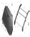
Figure 1 is a perspective view of one example of a swing-in-place vehicle article carrier system in accordance with the present disclosure mounted on a roof of a vehicle, and with the cross bar assemblies thereof positioned in their stowed positions adjacent their respective support rail assemblies; -
Figure 2 is another perspective view of the system ofFigure 1 but looking at the system from above and from a rearward angle; -
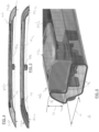
Figure 3 is a side view of the support rail assembly on the driver's side of the vehicle, and helping to illustrate generally how the assembly looks to an individual standing alongside the driver's side of the vehicle; -
Figure 4 shows a side view of the inside of the support rail assembly which is mounted adjacent the passenger side of the vehicle, illustrating the compact construction and appearance of the cross bar assembly being an integrally formed portion of the support rail assembly when in its stowed position; -
Figure 5 is a perspective, cross-sectional view of a portion of the main rail portion illustrating the dimensions of the vertical and horizontal sections of the L-shaped main rail portion, which enable the cross bar assembly to be nestably supported in a compact, hidden manner thereon when mounted in its stowed position; -
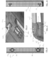
Figure 6 is an exploded perspective view of the components used to form the example embodiment of the support rail assembly which is mounted adjacent the driver's side of the vehicle in the drawing ofFigure 1 ; -
Figure 7 is an exploded perspective view of the components of the example embodiment of the support rail assembly which is mounted adjacent the passenger side of the vehicle in the drawing ofFigure 1 ; -
Figure 8 is a plan view of a rear area of the main rail portion used in the driver's side support rail assembly shown inFigure 1 , illustrating the two mounting locations available for mounting the rear cross bar assembly in its two longitudinally different operative locations; -
Figure 9 is a top perspective view of a portion of the rear support foot associated with the driver's side support rail assembly, illustrating the mounting element used to secure the rear cross bar in its rearward most operative position; -
Figure 10 is a plan view of just a portion of the main rail portion of the passenger side support rail assembly illustrating the channel which allows sliding repositioning of the pivotally secured end of the rear cross bar assembly between its two different operative positions; -
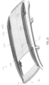
Figure 11 shows a perspective side view of another embodiment of the passenger side support rail assembly and the rear cross bar assembly in which the pivoting end of the rear cross bar assembly is fully removable, and in which the rear support foot includes an integrally formed circumferential ramp portion which helps to prevent contact of the rear cross bar assembly with the vehicle outer body roof surface if the user should accidentally release the rear cross bar assembly before the opposite end is positioned fully over one or the other of the support rail assemblies; -
Figure 12 shows a swing-in-place rack system in accordance with another embodiment of the present disclosure in which the support rail assemblies each make use of a single piece, stretch formed main rail portion, which enables a dramatic reduction in the number of independent component parts needed to fully implement each support rail assembly; and -
Figure 13 shows an exploded perspective view of the passenger side support rail assembly ofFigure 12 , illustrating the dramatically reduced number of independent components needed for this embodiment of the support rail assembly. - Example embodiments will now be described more fully with reference to the accompanying drawings.
- Referring to
Figures 1 and 2 , one embodiment of a swing-in-place rack system 10 in accordance with the present disclosure is shown. Thesystem 10 includes a pair of support rails assemblies 12a and 12b which are fixedly secured to an outerbody roof surface 14 of a motor vehicle 16. In this example the support rail assembly 12a is fixedly secured along a longitudinal length of the outer bodyvehicle roof surface 14 adjacent the driver's side of the vehicle 16, while the support rail assembly 12b is similarly secured adjacent the passenger side of the vehicle. Each support rail assembly 12a and 12b includes amain rail portion 18a or 18b supported between a front support foot assembly 20a or 20b, and a rear support foot assembly 22a or 22b. A front cross bar assembly 24a may be pivotally secured at one end and latched at its opposite end to the support rail assembly 12a to place it in a stowed position over the main rail portion 18a. Similarly, a rearcross bar assembly 24b may be pivotally secured at one end to the support rail assembly 12b, and latched at its opposite end to the support rail assembly 12b, to place it in a stowed position over themain rail portion 18b. As is well known with swing-in-place style rack systems, the lengths of thecross bar assemblies 24a and 24b are tailored such that they can be stowed on their respective support rails assemblies 12a and 12b, and when positioned perpendicularly in their operative positions, the support rail assemblies 12a and 12b are perfectly located, width-wise, on the outer bodyvehicle roof surface 14 to enable attachment of the free ends of the cross bar assemblies to opposite ones of the support rail assemblies 12a or 12b. - An important feature of each rail
main portion 18a and 18b is its generally L-shaped construction, when viewed in cross section, as shown inFigure 5 . This feature will be discussed in greater detail in the following paragraphs. The L-shaped cross-sectional construction enables each of thecross bar assemblies 24a and 24b to rest within the L-shaped configuration of their associated support rails 12a and 12b, respectively, and be completely hidden from view, or virtually completely hidden from view, when a person stands along the driver's side or the passenger side of the vehicle 16 and looks at thesystem 10. - The hidden cross bar assembly feature mentioned above can be seen even better in
Figure 3 . From this view (i.e., standing alongside the driver's side of the vehicle 16), it appears that the support rail assembly 12a only incorporates the support foot assemblies 20a and 22a and the main rail portion 18a, and that no cross bar 24a is present on the support rail 12a. The same appearance would be present looking from the passenger side of the vehicle 16 when viewing the support rail assembly 12b. This provides an extremely clean, aesthetically pleasing appearance for thesystem 10. And as shown inFigure 4 , even thecross bar assembly 24b on the opposite side of the vehicle 16, while possibly being just slightly visible from some angles while standing on the driver's side of the vehicle 16, will still be very inconspicuous. This is largely because of how thecross bar assemblies 24a and 24b are both compactly housed on their respectivemain rail portions 18a and 18b when mounted in their stowed positions. And even as shown inFigure 4 , when viewing the inside of the support rail assembly 12b, thecross bar assembly 24b has the general appearance of being an integrally formed portion of the support rail assembly 12b. - With further reference to
Figure 5 , the L-shaped cross-sectional construction of themain rail portion 18b can be seen. Again, the main rail portion 18a has this same cross-sectional shape, and will appear as a mirror image of themain rail portion 18b when the two support rail assemblies 12a and 12b are installed on the vehicle outerbody roof surface 14. InFigure 5 it can be seen that the railmain portion 18b has a horizontal shelf portion 18' and a vertical wall portion 18". The vertical wall portion 18" is about equal (i.e., level with) the upper surface of thecross bar assembly 24b, as indicated by arrow "H", while the horizontal shelf portion 18' is about equal in length to a cross-sectional width of thecross bar assembly 24b, as indicated by arrow "L". As such, thecross bar assembly 24b can be generally concealed from view when standing along the passenger side of the vehicle 16 because it does not extend above the upper edge of the vertical wall portion 18". Nor does thecross bar assembly 24 extend beyond an inward edge of the horizontal shelf portion 18' when mounted in its stowed position. This further helps to provide a clean, aesthetically pleasing appearance to therack system 10 when it is viewed from the front or rear while thecross bar assemblies 24a and 24b are both mounted in their stowed positions. Still another advantage is that the horizontal shelf portions 18' of the support rail assemblies 12a and 12b lie within a common horizontal plane, which enables both of thecross bar assemblies 24a and 24b be positioned level when they are in their operative positions (assuming the vehicle 16 is on level ground), and both to be positioned at the same vertical height when positioned in their stowed positions on their respective support rail assembly 12a or 12b. This further helps to create a highly aesthetically pleasing appearance whether thecross bar assemblies 24a and 24b are secured in their operative or stowed positions. - The ability to stow the
cross bar assemblies 24a and 24b on their respectivemain rail portions 18a and 18b, respectively, without the cross bar assemblies projecting above the main rail portions 18, or inwardly beyond the inner edges of themain rail portions 18a and 18b, also helps to significantly reduce the aerodynamic drag imposed by thesystem 10 while the vehicle 16 is travelling at intermediate or highway speeds, and potentially helps to eliminate, or substantially reduce, any wind noise that might be encountered when the vehicle is operated with thecross bar assemblies 24a and 24b mounted in their stowed positions. Whether viewing the vehicle 16 from the side, from the front or from the rear, the stowedcross bars 24a and 24b appear to be integral portions of the main support rail assemblies 12a and 12b when mounted in their stowed positions, and thus make for a very aesthetically clean looking and highly aerodynamic configuration. - With reference to
Figure 6 , the cross bar assembly 24a and various other components of the support rail assembly 12a are shown. It will be understood that the support rail assembly 12b, shown inFigure 7 , is virtually a mirror image in its construction, and therefore will not be described in detail, with only differences between the two assemblies being noted in the following discussion. The support rail assembly 12a ofFigure 6 includes the main rail portion 18a which telescopically engages with structural mounting portions 26a and 28a of the front and rear support foot assemblies 22a and 22b, respectively. The front and rear structural mounting portions 26a and 28a may be of aluminum die cast construction or otherwise made from similarly robust construction techniques and materials (e.g., high strength plastics). The structural mounting portions 26a and 28a are attached to the outerbody roof surface 14 of the vehicle 16 and telescopically receive the opposing ends of the main rail portion 18a. A front lower cover element 30a and a rear lower cover element 32a (e.g., both made from plastic), as well as front and rear mounting pads 34a and 36a, are interposed between the structural mounting portions and the outerbody roof surface 14. Conventional threaded fasteners (or a combination of threaded fasteners and suitable adhesives) may be used to secure the structural mounting portions 26a and 28a to the outerbody roof surface 14. Decorative front and rear cover portions 38a and 40a may also be secured over the front and rear structural mounting portions 26a and 28a, respectively. A center support assembly comprised of components structural mounting portions 46a, 48a and 50a may be interconnected using conventional threaded fasteners to secure a midpoint of the main rail portion 18a to the vehicle outerbody roof surface 14 to provide added support and rigidity to the main rail portion 18a. - With further reference to
Figures 6 and 7 , the cross bar assembly 24a includes a first end having a pivot assembly 52 and a second end having a manually actuatable latching assembly 54. The pivot assembly 52 is coupled to a mounting surface 56 on the front structural mounting portion 28a. The latching assembly 54 may be engaged with an opening 58 in the main rail portion 18a to hold the cross bar assembly 24a in the stowed position on the main rail portion 18a, when not in use. When positioned extending perpendicularly between the two front support feet 20a and 20b, the latching assembly 54 passes through an opening 60 (Figure 7 ) in themain rail portion 18b and into engagement with a portion of a front structural mounting portion 26b of the support rail assembly 12b. This places the front cross bar assembly 24a in its operative position extending perpendicularly between the two support rail assemblies 12a and 12b. - With further reference to
Figures 6 and 7 , the support rail assembly 12b is similar in construction to the support rail assembly 12a, and components in common will be designated with the same reference number used to describe the support rail assembly 12a but with a "b" suffix. InFigure 6 it will be noted that the support rail assembly 12a further includes a mounting element 62 fixedly secured by conventional threaded fasteners within the main rail portion 18a, and accessible through an opening 76 formed in the main rail portion. Themain rail portion 18b includes achannel 64 formed along a portion of its length, and generally in the rear half of the length thereof. Thechannel 64 is also shown inFigure 10 . A slidable securing element, in this example aslide block 66, with an associated elastomeric O-ring 67 and a threaded fastener plate 68, are all positioned inside themain rail portion 18b, and coupled to apivot assembly 70 associated with a first (i.e., pivoting) end of the rearcross bar assembly 24b, which enables pivoting of the rearcross bar assembly 24b between the stowed position, wherein it is arranged parallel to themain rail portion 18b, and its operative position wherein it extends perpendicularly between the rear support foot assemblies 22a and 22b. Thepivot assembly 70, as well as the pivot assembly 52 (Figure 6 ), may each be constructed in accordance with the teachings of one or more of the above referenced U.S. Patents, which enables a small degree of pivotal motion within a vertical plane, as well as the needed pivoting motion within a horizontal plane, to enable lifting thecross bar 24a or 24b vertically a small degree while repositioning thecross bar assembly 24a or 24b to one or the other of the support rail assemblies 12a or 12b. The O-ring 67 provides the beneficial feature of providing a small degree of resilience in the attachment of thecross bar 24a or 24b which allows its associated cross bar to be lifted vertically a small amount, while still permitting pivoting motion in the horizontal plane, and while still enabling a sufficiently secure attachment of the pivoting end of each cross bar assembly to prevent any rattling during use of the vehicle 16. The opposite end of the rearcross bar assembly 24b includes a user engageable latching assembly 72 which may be identical in construction to the latching assembly 54. This construction allows the latching assembly 72 to be engaged with structural portion 60 when the rearcross bar assembly 24b is stowed on themain rail portion 18b, or engaged in a first operative position with the opening 58, or a second operative position at the opening 76, more forwardly positioned, with the mounting element 62. Thus, the rearcross bar assembly 24b has three possible mounting positions, one being a stowed position on its associatedmain rail portion 18b, a second being a rearward most operative position, and the third being an intermediate position closer to the front of the vehicle 16. These two rearward mounting positions are shown inFigure 2 , with it being understood one or the other, but not both, will be used at any given time. This provides significant added flexibility in carrying articles of widely varying dimensions. Thepivot assembly 70 can be secured at either extreme end of thechannel 64, to thus help hold the rearcross bar assembly 24b in any one of the above three described positions, by simply tightening a threaded element 71 (Figure 7 ) that extends therethrough and engages the threaded fastener plate 68. - With further brief reference to
Figure 6 and 7 , it will be appreciated that the latching assemblies 54 and 72 are well known in the art. These types of user engageable latching assemblies, for example, are disclosed inU.S. Patents Nos. 6,811,066 and7,066,364 , assigned to the assignee of the present disclosure. Suitable pivot assemblies for use with a cross bar are also disclosed in these patents. Furthermore, it will be appreciated that the various components shown inFigure 7 and denoted with reference numbers having the suffix "b" are the counterparts to those described above and shown inFigure 6 . - In
Figure 8 a plan view of a rear portion of the main rail portion 18a is shown with the mounting element 62 fixedly secured within the main rail portion. The rear structural mounting portion 28a includes an integrally secured mountingelement 74, as also shown inFigure 9 , which is inserted within the main rail portion 18a when the rear structural mounting portion 28a is assembled to the main rail portion 18a during assembly of the support rail assembly 12a. The main rail portion 18a includes the generally circular opening 76 and an additional generally circular opening 78, which each expose theirrespective mounting elements 62 and 74. This enables the latching assembly 54 of the rearcross bar assembly 24b to engage either one of the mountingelements 62 or 74, depending on which of the two rearward locations it is being mounted at. And as noted above, the latching assembly 54 of the front cross bar assembly 24a engages the mountingelement 74 when it is positioned in its stowed position on the support rail assembly 12a. - Referring briefly to
Figure 10 , thechannel 64 in themain rail portion 18b forms a track which can be seen better along with theslide block 66 positioned therein. Theslide block 66 is shown in both of its potential rearward mounting positions, although it will be appreciated that in actual use of thesystem 10 there is only oneslide block 66 being used. Theslide block 66 is held at a specific position by tightening of the threadedexternal fastener element 71 to the fastener plate 68. This construction secures thepivot assembly 70 to themain rail portion 18b while still allowing both pivoting motion of the rearcross bar assembly 24b, as well as linear sliding movement of thepivot assembly 70, at one end of the rearcross bar assembly 24b. - Referring briefly to
Figure 11 , it will be appreciated that while thesystem 10 makes use of the rearcross bar assembly 24b being pivotally attached at one end, that instead both ends of the rearcross bar assembly 24b could be fully detachable from the support rail assemblies 12a and 12b, and two spaced apart, discrete mounting locations provided for near the rear ends of the support rail assemblies 12a and 12b.Figure 11 shows this modification where a prime (') symbol is used to help denote components which may correspond to those used to describe thesystem 10 inFigures 1-10 . For example, the rearcross bar assembly 24b' inFigure 11 has a pivot assembly 70' construction which incorporates a threaded element 71' which extends therethrough and which engages a suitable threaded plate or element (not shown inFigure 11 ) fixedly mounted within the support rail assembly 12b'. As such, manual removal of the threaded element 71' enables the pivot assembly 70' to be completely lifted off of its associated support rail assembly 12b' and moved to a more forward position on the support rail assembly 12b' and then re-secured thereto using the same threaded element 71'. This configuration also allows therear cross bar 24b' to be pivoted into its operative position, when mounted as shown inFigure 11 , by simply rotating thecross bar assembly 24b' perpendicularly until the opposite end is positioned over the other support rail assembly 12a. -
Figure 11 shows another feature that may be incorporated into thesystem 10 which prevents the rearcross bar assembly 24b' from falling on the outerbody roof surface 14 if the user accidentally loses his/her grip on theassembly 24b' while moving the rear cross bar assembly from its stowed position into its operative position, or from its operative position into its stowed position. This involves incorporating a housing 80' having a lower surface 82' for the pivot assembly 70'. A rear support foot 22b' includes a circumferential ramp portion 84' projecting up from an upper surface 86' thereof. The ramp portion 84' cooperates with the lower surface 82' by contacting the lower surface 82' to prevent thecross bar assembly 24b' from dropping down onto the outerbody roof surface 14 of the vehicle 16 if the user should accidentally release thecross bar assembly 24b' before the latching assembly 72 at its opposite end is positioned over the support rail assembly 12a. In such an instance, the latching assembly 72 will be held above the outerbody roof surface 14 by contact with the ramp portion 84'. This feature also enables shorter individuals who may not be able to maneuver thecross bar assembly 24b easily into its fully perpendicular extending position to initiate the process from one side of the vehicle 16 by moving the rear cross bar assembly to an intermediate position over the outerbody roof surface 14, and then going to the other side of the vehicle to reach up and pull the opposite end of the rearcross bar assembly 24b into its fully perpendicular position for attachment to the support rail assembly 12a. It will be appreciated that this feature may be incorporated into the front support foot 20a as well if desired. - Referring now to
Figure 12 , a swing-in-place vehiclearticle carrier system 100 in accordance with another embodiment of the present disclosure is shown. Thesystem 100 is similar in operation to thesystem 10, but instead of a multi-piece support rail construction as used for the support rail assemblies 12a and 12b, which requires the structural mounting portions 26a and 28a, thesystem 100 makes use of one piece support rail assemblies 102a and 102b. This construction dramatically reduces the construction complexity of the support rail assemblies 102a and 102b, while providing even further enhanced structural capability due to its single piece construction. Support rail assembly 102a houses a front cross bar assembly 104a, while support rail assembly 102b houses a rear cross bar assembly 104b. The front cross bar assembly 104a has a first end with apivot assembly 106a which provides for pivotal movement of the cross bar assembly 104a between it stowed position and its operative position, while the opposite end includes a latchingassembly 108a which allows the front cross bar assembly to be secured in its operative position, or as well as in its stowed position. The rear cross bar assembly 104b similarly includes a pivot assembly 108b located at its rear end, and a latchingassembly 106a located at its front end, enabling the rear cross bar assembly to be pivoted and secured in either one of two different operative positions near a rear area of the support rail assemblies 102a and 102b. In this example the rear cross bar assembly 104b is fully removable to enable the rearward mounting at two different positions, as described above with respect toFigure 10 . Thesystem 100 provides the same benefits as thesystem 10 in that the cross bar assemblies 104a and 104b are hidden from view when placed in their stowed positions, and when an individual is viewing the vehicle 16 from most angles around the perimeter of the vehicle. - Referring to
Figure 13 , an exploded perspective view of the components of the support rail assembly 102b are shown to illustrate the dramatically reduced number of individual component parts which make up its construction. It will be appreciated that the support rail assembly 102a may be of nearly identical construction, with the principal differences being the positioning of the components which engage with thelatching assemblies 108a to enable the cross bar assemblies 104a and 104b to be placed in their stowed and operative positions. - Of primary importance in the construction of the support rail assembly 102b shown in
Figure 13 is a single piece, stretch bent main rail portion 110b, which may be made from any suitable material, but preferably is made from aluminum or steel. The main rail portion 110b has a central portion 112b having the L-shaped cross-sectional construction described herein for the support rail assemblies 12a and 12b, but also includes an integrally formed curving front, portion 114b at one end, and an integrally formed curving rear portion 116b at its other end. A front structural mounting block 118 (e.g., die-cast aluminum or steel) with integrated threaded fasteners is secured to the curving front portion 114b of the main rail portion 110b and to a decorative lower/outer cover member 120 by using threadedfasteners 122. The decorative lower/outer cover has a shape and profile to fit under the curving front portion 114b of the main rail portion 110b. A separate plurality of threadedscrews 124 is used to secure a decorative upper cover member 126 to the lower/outer cover member 120 such that the curving front portion 114b is partially encapsulated between the two decorative cover members 120 and 126. A resilient pad 128 is placed directly against the outerbody roof surface 14, and lower areas of the two decorative cover members 120 and 126 rest against the pad 128, which serves to take up any gaps between the decorative cover members 120/126 and the outerbody roof surface 14. A similar construction is present at the curving rear portion 116b of the main rail portion 110b, where a structural mounting block 130 with integrated threaded fasteners is secured to the curving rear portion 116b, and to a decorative rear lower cover member 132, via threadedfasteners 134. A decorative rear upper/inner cover member 136 is secured to the decorative rear lower cover member 132 via a separate plurality of threaded fasteners 138, which partially encapsulates the rear portion 116b of the main rail portion 110b. Aresilient pad 140 is placed between the outerbody roof surface 14 and the decorative rear cover members 132/136 to help take up any gaps between these components and the outer body roof surface. This configuration enables the curving front and rear portions 114b and 116b of the main rail portion 110b to be directly secured to the vehicleouter body surface 14, which allows forces experienced by the main rail portion 110b to be transferred directly into theouter body surface 14 rather than into an intermediate component. This construction not only significantly enhances the strength of the main rail portion 110b, but also significantly enhances its overall rigidity as well. The reduced number of independent component parts also reduces costs and enables even quicker and easier assembly of the support rail assembly 102b on the vehicle 16. - With further reference to
Figure 13 , a front cross bar mounting element 142 is fixedly secured with threaded fasteners 144 to the main rail portion, which provides the point of attachment for the latchingassembly 108a of the front cross bar assembly 104a when the front cross bar assembly is secured in its operative position. Similarly, a pair of rear cross bar mounting elements 146 and 148 are secured to the main rail portion 110b via pairs of threaded fasteners 150 and 152, respectively. The rear cross bar mounting elements 146 and 148 define the two operative positions for the rear cross bar assembly 104b, while the rearward most cross bar mounting element 146 also operates to provide an attachment point for the rear cross bar assembly 104b when it is secured in its stowed position over the support rail assembly 102b. - The foregoing description of the embodiments has been provided for purposes of illustration and description. It is not intended to be exhaustive or to limit the disclosure. Individual elements or features of a particular embodiment are generally not limited to that particular embodiment, but, where applicable, are interchangeable and can be used in a selected embodiment, even if not specifically shown or described. The same may also be varied in many ways. Such variations are not to be regarded as a departure from the disclosure, and all such modifications are intended to be included within the scope of the disclosure.
- Example embodiments are provided so that this disclosure will be thorough, and will fully convey the scope to those who are skilled in the art. Numerous specific details are set forth such as examples of specific components, devices, and methods, to provide a thorough understanding of embodiments of the present disclosure. It will be apparent to those skilled in the art that specific details need not be employed, that example embodiments may be embodied in many different forms and that neither should be construed to limit the scope of the disclosure. In some example embodiments, well-known processes, well-known device structures, and well-known technologies are not described in detail.
- The terminology used herein is for the purpose of describing particular example embodiments only and is not intended to be limiting. As used herein, the singular forms "a," "an," and "the" may be intended to include the plural forms as well, unless the context clearly indicates otherwise. The terms "comprises," "comprising," "including," and "having," are inclusive and therefore specify the presence of stated features, integers, steps, operations, elements, and/or components, but do not preclude the presence or addition of one or more other features, integers, steps, operations, elements, components, and/or groups thereof. The method steps, processes, and operations described herein are not to be construed as necessarily requiring their performance in the particular order discussed or illustrated, unless specifically identified as an order of performance. It is also to be understood that additional or alternative steps may be employed.
- When an element or layer is referred to as being "on," "engaged to," "connected to," or "coupled to" another element or layer, it may be directly on, engaged, connected or coupled to the other element or layer, or intervening elements or layers may be present. In contrast, when an element is referred to as being "directly on," "directly engaged to," "directly connected to," or "directly coupled to" another element or layer, there may be no intervening elements or layers present. Other words used to describe the relationship between elements should be interpreted in a like fashion (e.g., "between" versus "directly between," "adjacent" versus "directly adjacent," etc.). As used herein, the term "and/or" includes any and all combinations of one or more of the associated listed items.
- Although the terms first, second, third, etc. may be used herein to describe various elements, components, regions, layers and/or sections, these elements, components, regions, layers and/or sections should not be limited by these terms. These terms may be only used to distinguish one element, component, region, layer or section from another region, layer or section. Terms such as "first," "second," and other numerical terms when used herein do not imply a sequence or order unless clearly indicated by the context. Thus, a first element, component, region, layer or section discussed below could be termed a second element, component, region, layer or section without departing from the teachings of the example embodiments.
- Spatially relative terms, such as "inner," "outer," "beneath," "below," "lower," "above," "upper," and the like, may be used herein for ease of description to describe one element or feature's relationship to another element(s) or feature(s) as illustrated in the figures. Spatially relative terms may be intended to encompass different orientations of the device in use or operation in addition to the orientation depicted in the figures. For example, if the device in the figures is turned over, elements described as "below" or "beneath" other elements or features would then be oriented "above" the other elements or features. Thus, the example term "below" can encompass both an orientation of above and below. The device may be otherwise oriented (rotated 90 degrees or at other orientations) and the spatially relative descriptors used herein interpreted accordingly.
Claims (15)
- A vehicle article carrier system for carrying articles elevationally above an outer body surface of a vehicle, the system comprising:first and second support rail assemblies fixed supported on an outer body roof surface parallel to one another, the first support rail being secured adjacent a first side of the vehicle, and the second support rail being secured adjacent a second side of the vehicle;a first cross bar configured to be secured in a stowed position on the first support rail assembly, and in an operative position extending parallel between the first and second support rail assemblies and secured to the first and second support rail assemblies;a second cross bar configured to be secured in a stowed position on the second support rail assembly, and in an operative position extending perpendicularly between the first and second support rail assemblies and secured to the first and second support rail assemblies;each of the first and support rail assemblies including:a main rail portion having an L-shape when viewed endwise;the L-shape having a vertical wall portion and a horizontal shelf portion; andthe vertical wall portion having a height sufficient to extend at least to an upper surface of its associated said first or second cross bar when its associated said first or second cross bar is positioned in the stowed position, to thus hide said first or second cross bar; andwherein the first cross bar, when in the stowed position, is not visible when viewing the first support rail from the first side of the vehicle, and the second cross bar is not visible, when in the stowed position, when viewing the second support rail assembly from the second side of the vehicle.
- The system of claim 1, wherein the horizontal shelf portion of each one of said first and second support rail assemblies extends perpendicularly from the vertical wall portion, and
wherein either the first and second cross bars are positioned over a respective one of the horizontal shelf portions when disposed in their stowed positions. - The system of claim 2, wherein a dimension of the horizontal shelf portion of the first support rail assembly is equal to a width of the first cross bar, and a dimension of the horizontal shelf portion of the second support rail assembly is equal to a width of the second cross bar.
- The system of claim 1, wherein a first end of the first cross bar is pivotally secured to the first support rail assembly.
- The system of claim 1, wherein the first end of the second cross bar is pivotally secured to the second support rail assembly.
- The system of claim 5, wherein the first end of the second cross bar assembly is slidably movable along a portion of the second support rail assembly to define at least first and second apart operative positions for the second cross bar.
- The system of claim 6, wherein:the second support rail assembly includes an elongated linear slot and a slide block engaged therewith; andthe first end of the second cross bar is engaged with the slide block to permit movement of the first end of the second cross bar along the elongated linear slot.
- The system of claim 7, wherein the elongated linear slot defines two spaced apart securing locations for securing the first end of the second cross bar.
- The system of claim 1, wherein a first end of the second cross bar includes a fastening element to enable detachment of the first end of the second cross bar at a first mounting location on the second support rail assembly, and reattachment of the first end of the second cross bar at a second mounting location on the second support rail assembly which is spaced apart from the first mounting location.
- The system of claim 1, wherein:a first end of the first cross bar is pivotally secured to the first support rail assembly and a second end of the first cross bar assembly includes a first latching assembly for engaging with the second support rail assembly to hold the first cross bar in the operative position; anda first end of the second cross bar is pivotally secured to the second support tail and a second end of the second cross bar assembly includes a second latching assembly for engaging with the first support rail assembly to secure the second cross bar in the operative position.
- The system of claim 1, wherein:the second support rail assembly includes a support foot; andwherein the support foot includes a raised ramp portion which cooperates with a first end of the second cross bar to prevent a second end of the second cross bar from touching the outer body roof surface of the vehicle when the second cross bar is released and the second end is positioned between the first and second support rail assemblies.
- The system of claim 1, wherein at least one of the first or second support rail assemblies includes a single piece, stretch formed main rail portion having an integrally formed central portion and enlarged end portions, and where the enlarged end portions are configured to be secured via external fasteners to the outer body roof surface of the vehicle.
- The system of claim 1, wherein the horizontal shelf portions of the first and second support rail assemblies are further arranged to extend perpendicularly toward one another in a common horizontal plane.
- The system of claim 1, wherein the horizontal shelf portion of the first support rail assembly has a length dimension sufficient to extend fully under the first cross bar when the first cross bar is placed in the stowed position on the first support rail assembly.
- The system of claim 13, wherein the horizontal shelf portion of the second support rail assembly has a length dimension sufficient to extend fully under the second cross bar when the second cross bar is placed in the stowed position on the second support rail assembly.
Applications Claiming Priority (1)
| Application Number | Priority Date | Filing Date | Title |
|---|---|---|---|
| US17/453,581 US11912240B2 (en) | 2021-11-04 | 2021-11-04 | Vehicle article carrier rack system with stowable, concealable cross bars |
Publications (1)
| Publication Number | Publication Date |
|---|---|
| EP4177112A1 true EP4177112A1 (en) | 2023-05-10 |
Family
ID=82742617
Family Applications (1)
| Application Number | Title | Priority Date | Filing Date |
|---|---|---|---|
| EP22186985.2A Pending EP4177112A1 (en) | 2021-11-04 | 2022-07-26 | Vehicle article carrier rack system with stowable, concealable cross bars |
Country Status (2)
| Country | Link |
|---|---|
| US (1) | US11912240B2 (en) |
| EP (1) | EP4177112A1 (en) |
Citations (14)
| Publication number | Priority date | Publication date | Assignee | Title |
|---|---|---|---|---|
| US5511709A (en) | 1993-06-29 | 1996-04-30 | Happich Fahrzeug-Dachsysteme Gmbh | Roof rack for motor vehicles |
| US6286739B1 (en) * | 1999-09-29 | 2001-09-11 | Sportrack Llc | Article carrier with stowing crossrails |
| EP1470960A1 (en) * | 2003-04-23 | 2004-10-27 | Peugeot Citroen Automobiles S.A. | Vehicle roof rack assembly |
| US6811066B2 (en) | 2001-10-26 | 2004-11-02 | Jac Products Inc. | Vehicle article carrier having stowable cross bars |
| US7066364B2 (en) | 2002-10-24 | 2006-06-27 | Jac Products, Inc. | Vehicle article carrier having stowable cross bars |
| US7090103B2 (en) | 2002-10-24 | 2006-08-15 | Jac Products, Inc. | Vehicle article carrier having stowable cross bars |
| FR2939386A1 (en) * | 2008-12-05 | 2010-06-11 | Peugeot Citroen Automobiles Sa | Roof rod assembly for motor vehicle, has transversal bar associated to respective longitudinal bar, where longitudinal bar includes guiding unit for guiding associated transversal bar along predetermined overlapping path |
| US8028875B2 (en) | 2006-10-26 | 2011-10-04 | Jac Products, Inc. | Vehicle article carrier having swing in place cross bars |
| US8096454B2 (en) | 2008-10-01 | 2012-01-17 | Jac Products, Inc. | System and method for vehicle article carrier having stowable cross bars |
| US8235264B2 (en) | 2008-10-01 | 2012-08-07 | Jac Products, Inc. | System and method for vehicle article carrier having stowable cross bars |
| US8251267B2 (en) | 2007-06-13 | 2012-08-28 | Jac Products, Inc. | Vehicle article carrier having single sided releasable and stowable cross bars |
| US8276794B2 (en) | 2007-06-13 | 2012-10-02 | Jac Products, Inc. | Vehicle article carrier having releasable and stowable cross bars |
| US8528799B2 (en) | 2008-10-01 | 2013-09-10 | Jac Products, Inc. | System and method for vehicle article carrier having stowable cross bars |
| US20160243994A1 (en) | 2015-02-23 | 2016-08-25 | Jac Products, Inc. | System and method for vehicle article carrier having stowable cross bars |
Family Cites Families (34)
| Publication number | Priority date | Publication date | Assignee | Title |
|---|---|---|---|---|
| US5069377A (en) * | 1990-12-10 | 1991-12-03 | Alton Baughman | Roof rack for vehicles |
| US5393114A (en) | 1991-09-19 | 1995-02-28 | Christensen; David | Reversible utility rail and utility rack |
| DE4321537A1 (en) * | 1993-06-29 | 1995-01-12 | Happich Gmbh Gebr | Roof rails for vehicles |
| DE4323098A1 (en) * | 1993-07-10 | 1995-01-12 | Happich Gmbh Gebr | Roof rails for vehicles |
| ATE154299T1 (en) * | 1993-10-18 | 1997-06-15 | Erbsloeh Ag | ROOF RAILS FOR VEHICLES |
| US5494327A (en) | 1995-01-31 | 1996-02-27 | Tracrac, Inc. | Sliding connection for releasably and adjustably attaching an overhead rack to a pickup truck |
| JP3560515B2 (en) * | 1999-09-30 | 2004-09-02 | ジー・ピー・ダイキョー株式会社 | Vehicle roof rack |
| US6431634B1 (en) | 2001-01-16 | 2002-08-13 | Frederick Ananian | Collapsible truck shell assembly and accessories |
| CA2358377A1 (en) | 2001-10-10 | 2003-04-10 | Donald Martin | Truck carrier |
| US20040134953A1 (en) | 2003-01-09 | 2004-07-15 | Perez Carlos Valadez | Multi positionable rack for a pick up truck bed |
| US20050023314A1 (en) | 2003-07-30 | 2005-02-03 | Ford Motor Company | Telescoping roof rack assembly for a vehicle having a truck bed |
| US7296836B1 (en) | 2004-06-07 | 2007-11-20 | Zeljko Sabo | Truck rack apparatus |
| DE102005018158A1 (en) * | 2004-09-24 | 2006-04-06 | Hans und Ottmar Binder GmbH Oberflächenveredelung | Roof rack system for a vehicle and method of making the roof rack system and vehicle having a roof rack system |
| AU2006306505A1 (en) | 2005-10-21 | 2007-05-03 | Connaught Construction Company | Raisable truck bed cover |
| US7296837B2 (en) | 2005-10-31 | 2007-11-20 | Thule Sweden A.B. | Load carrier arrangement for a vehicle bed comprising an internal bed rail system |
| US20080100075A1 (en) | 2006-10-31 | 2008-05-01 | Derecktor Thomas E | Sliding overhead rack for pickup trucks |
| US7464977B1 (en) | 2007-03-16 | 2008-12-16 | Price Brent A | Elevating long cargo support assembly for pickup truck |
| US8485403B2 (en) * | 2008-03-27 | 2013-07-16 | GM Global Technology Operations LLC | Roof rack assembly with stowable cross members |
| CA2670173C (en) * | 2008-06-27 | 2016-11-29 | Magna International Inc. | Roof rack with stowable non-adjustable crossbars |
| US20100072237A1 (en) | 2008-09-25 | 2010-03-25 | Christopher Phillip Green | Disassemblable Rack Having Dual Mounting Crossbars for Use with Pickup Trucks and SUVs |
| US9981612B2 (en) | 2009-05-18 | 2018-05-29 | Thule Inc. | Modular rack system with gussetless joints |
| US8376684B2 (en) | 2010-04-12 | 2013-02-19 | Pedro A. Juarez-Ortega | Loader and carrier apparatus |
| US9725046B2 (en) | 2012-07-31 | 2017-08-08 | Thule Sweden Ab | Demarcated height adjustable load carrier rack |
| US9150161B2 (en) | 2012-07-31 | 2015-10-06 | Thule Sweden Ab | Vehicular load carrier rack with locking cover |
| AU2013301209B2 (en) | 2012-08-07 | 2017-08-24 | Jack FINESTONE | A load carrying assembly |
| US9352696B2 (en) * | 2013-11-11 | 2016-05-31 | Honda Motor Co., Ltd. | Low profile roof rail |
| US9132784B2 (en) | 2014-01-13 | 2015-09-15 | Daws Manufacturing Company, Inc. | Truck headache rack |
| CA2885043A1 (en) | 2014-03-13 | 2015-09-13 | Winston Breeden | Folding ladder rack |
| US10071692B2 (en) | 2015-03-30 | 2018-09-11 | Jac Products, Inc. | Pickup truck roof rack system |
| IT201700114809A1 (en) * | 2017-10-12 | 2019-04-12 | ATHANOR Srl | Device connectable to the trunk of a motor vehicle for a rapid preparation of the same for the safe transport of one or more packages, luggage carrier comprising said device and car equipped with a luggage carrier comprising said device |
| AU2019203756A1 (en) | 2018-06-01 | 2019-12-19 | Yakima Australia Pty Limited | Truck-Mountable Cargo Rack |
| US10850675B2 (en) * | 2018-08-20 | 2020-12-01 | Dura Operating, Llc | Stowable roof rack for a vehicle |
| CN210310582U (en) | 2019-06-28 | 2020-04-14 | 浙江阜康机械有限公司 | Simple vehicle goods shelf |
| US11052828B2 (en) | 2019-09-19 | 2021-07-06 | George Huisman | Cargo rack for trucks |
-
2021
- 2021-11-04 US US17/453,581 patent/US11912240B2/en active Active
-
2022
- 2022-07-26 EP EP22186985.2A patent/EP4177112A1/en active Pending
Patent Citations (15)
| Publication number | Priority date | Publication date | Assignee | Title |
|---|---|---|---|---|
| US5511709A (en) | 1993-06-29 | 1996-04-30 | Happich Fahrzeug-Dachsysteme Gmbh | Roof rack for motor vehicles |
| US6286739B1 (en) * | 1999-09-29 | 2001-09-11 | Sportrack Llc | Article carrier with stowing crossrails |
| US6811066B2 (en) | 2001-10-26 | 2004-11-02 | Jac Products Inc. | Vehicle article carrier having stowable cross bars |
| US7448523B2 (en) | 2002-10-24 | 2008-11-11 | Jac Products, Inc. | Vehicle article carrier having stowable cross bars |
| US7066364B2 (en) | 2002-10-24 | 2006-06-27 | Jac Products, Inc. | Vehicle article carrier having stowable cross bars |
| US7090103B2 (en) | 2002-10-24 | 2006-08-15 | Jac Products, Inc. | Vehicle article carrier having stowable cross bars |
| EP1470960A1 (en) * | 2003-04-23 | 2004-10-27 | Peugeot Citroen Automobiles S.A. | Vehicle roof rack assembly |
| US8028875B2 (en) | 2006-10-26 | 2011-10-04 | Jac Products, Inc. | Vehicle article carrier having swing in place cross bars |
| US8251267B2 (en) | 2007-06-13 | 2012-08-28 | Jac Products, Inc. | Vehicle article carrier having single sided releasable and stowable cross bars |
| US8276794B2 (en) | 2007-06-13 | 2012-10-02 | Jac Products, Inc. | Vehicle article carrier having releasable and stowable cross bars |
| US8096454B2 (en) | 2008-10-01 | 2012-01-17 | Jac Products, Inc. | System and method for vehicle article carrier having stowable cross bars |
| US8235264B2 (en) | 2008-10-01 | 2012-08-07 | Jac Products, Inc. | System and method for vehicle article carrier having stowable cross bars |
| US8528799B2 (en) | 2008-10-01 | 2013-09-10 | Jac Products, Inc. | System and method for vehicle article carrier having stowable cross bars |
| FR2939386A1 (en) * | 2008-12-05 | 2010-06-11 | Peugeot Citroen Automobiles Sa | Roof rod assembly for motor vehicle, has transversal bar associated to respective longitudinal bar, where longitudinal bar includes guiding unit for guiding associated transversal bar along predetermined overlapping path |
| US20160243994A1 (en) | 2015-02-23 | 2016-08-25 | Jac Products, Inc. | System and method for vehicle article carrier having stowable cross bars |
Also Published As
| Publication number | Publication date |
|---|---|
| US11912240B2 (en) | 2024-02-27 |
| US20230135957A1 (en) | 2023-05-04 |
Similar Documents
| Publication | Publication Date | Title |
|---|---|---|
| US11027660B2 (en) | Vehicle article carrier system having swing-in-place cross bars | |
| US20070065264A1 (en) | Sliding load floor system | |
| US8276794B2 (en) | Vehicle article carrier having releasable and stowable cross bars | |
| US8096454B2 (en) | System and method for vehicle article carrier having stowable cross bars | |
| US8251267B2 (en) | Vehicle article carrier having single sided releasable and stowable cross bars | |
| US20070108787A1 (en) | Vehicle Gap Guard | |
| US7802842B2 (en) | Roof module of a motor vehicle | |
| CA2391041A1 (en) | Vehicle article carrier having telescopically extendable article carrier portion | |
| US5253792A (en) | Luggage carrier with pop-up frame | |
| US5443191A (en) | Portable vehicle-mounted gun rack | |
| JP3168172B2 (en) | Vehicle article carrier | |
| US20120085269A1 (en) | Table Assembly | |
| US6533302B2 (en) | Step bar cradle and trim channel | |
| US20050082324A1 (en) | Article carrier and bicycle rack system | |
| EP4177112A1 (en) | Vehicle article carrier rack system with stowable, concealable cross bars | |
| US10071692B2 (en) | Pickup truck roof rack system | |
| US6257653B1 (en) | Wind baffle attachable to seats using straps | |
| US6371342B2 (en) | Cargo retention system | |
| US20030010797A1 (en) | Multipurpose steering wheel holder | |
| US6193298B1 (en) | Wind baffle attachable to seats using straps | |
| CA1115670A (en) | Luggage carrier for automotive vehicles and the like | |
| US10723272B2 (en) | Step rail system for vehicle | |
| EP2210778B1 (en) | Luggage carrying container for motor-vehicles. | |
| CN209833515U (en) | Roof rack module | |
| Guide | Reference Guide |
Legal Events
| Date | Code | Title | Description |
|---|---|---|---|
| PUAI | Public reference made under article 153(3) epc to a published international application that has entered the european phase |
Free format text: ORIGINAL CODE: 0009012 |
|
| STAA | Information on the status of an ep patent application or granted ep patent |
Free format text: STATUS: REQUEST FOR EXAMINATION WAS MADE |
|
| 17P | Request for examination filed |
Effective date: 20220801 |
|
| AK | Designated contracting states |
Kind code of ref document: A1 Designated state(s): AL AT BE BG CH CY CZ DE DK EE ES FI FR GB GR HR HU IE IS IT LI LT LU LV MC MK MT NL NO PL PT RO RS SE SI SK SM TR |
|
| STAA | Information on the status of an ep patent application or granted ep patent |
Free format text: STATUS: EXAMINATION IS IN PROGRESS |
|
| RBV | Designated contracting states (corrected) |
Designated state(s): AL AT BE BG CH CY CZ DE DK EE ES FI FR GB GR HR HU IE IS IT LI LT LU LV MC MK MT NL NO PL PT RO RS SE SI SK SM TR |
|
| 17Q | First examination report despatched |
Effective date: 20231204 |