EP4177104A1 - Child safety seat and detachable side collision protective block - Google Patents
Child safety seat and detachable side collision protective block Download PDFInfo
- Publication number
- EP4177104A1 EP4177104A1 EP21836876.9A EP21836876A EP4177104A1 EP 4177104 A1 EP4177104 A1 EP 4177104A1 EP 21836876 A EP21836876 A EP 21836876A EP 4177104 A1 EP4177104 A1 EP 4177104A1
- Authority
- EP
- European Patent Office
- Prior art keywords
- protection block
- locking
- child safety
- safety seat
- side impact
- Prior art date
- Legal status (The legal status is an assumption and is not a legal conclusion. Google has not performed a legal analysis and makes no representation as to the accuracy of the status listed.)
- Pending
Links
Images


Classifications
-
- B—PERFORMING OPERATIONS; TRANSPORTING
- B60—VEHICLES IN GENERAL
- B60N—SEATS SPECIALLY ADAPTED FOR VEHICLES; VEHICLE PASSENGER ACCOMMODATION NOT OTHERWISE PROVIDED FOR
- B60N2/00—Seats specially adapted for vehicles; Arrangement or mounting of seats in vehicles
- B60N2/24—Seats specially adapted for vehicles; Arrangement or mounting of seats in vehicles for particular purposes or particular vehicles
- B60N2/26—Seats specially adapted for vehicles; Arrangement or mounting of seats in vehicles for particular purposes or particular vehicles for children
- B60N2/28—Seats readily mountable on, and dismountable from, existing seats or other parts of the vehicle
- B60N2/2872—Seats readily mountable on, and dismountable from, existing seats or other parts of the vehicle provided with side rests
-
- B—PERFORMING OPERATIONS; TRANSPORTING
- B60—VEHICLES IN GENERAL
- B60N—SEATS SPECIALLY ADAPTED FOR VEHICLES; VEHICLE PASSENGER ACCOMMODATION NOT OTHERWISE PROVIDED FOR
- B60N2/00—Seats specially adapted for vehicles; Arrangement or mounting of seats in vehicles
- B60N2/24—Seats specially adapted for vehicles; Arrangement or mounting of seats in vehicles for particular purposes or particular vehicles
- B60N2/26—Seats specially adapted for vehicles; Arrangement or mounting of seats in vehicles for particular purposes or particular vehicles for children
- B60N2/28—Seats readily mountable on, and dismountable from, existing seats or other parts of the vehicle
- B60N2/2884—Seats readily mountable on, and dismountable from, existing seats or other parts of the vehicle with protection systems against abnormal g-forces
-
- B—PERFORMING OPERATIONS; TRANSPORTING
- B60—VEHICLES IN GENERAL
- B60N—SEATS SPECIALLY ADAPTED FOR VEHICLES; VEHICLE PASSENGER ACCOMMODATION NOT OTHERWISE PROVIDED FOR
- B60N2/00—Seats specially adapted for vehicles; Arrangement or mounting of seats in vehicles
- B60N2/24—Seats specially adapted for vehicles; Arrangement or mounting of seats in vehicles for particular purposes or particular vehicles
- B60N2/42—Seats specially adapted for vehicles; Arrangement or mounting of seats in vehicles for particular purposes or particular vehicles the seat constructed to protect the occupant from the effect of abnormal g-forces, e.g. crash or safety seats
- B60N2/4207—Seats specially adapted for vehicles; Arrangement or mounting of seats in vehicles for particular purposes or particular vehicles the seat constructed to protect the occupant from the effect of abnormal g-forces, e.g. crash or safety seats characterised by the direction of the g-forces
- B60N2/4235—Seats specially adapted for vehicles; Arrangement or mounting of seats in vehicles for particular purposes or particular vehicles the seat constructed to protect the occupant from the effect of abnormal g-forces, e.g. crash or safety seats characterised by the direction of the g-forces transversal
Definitions
- the present disclosure relates to the technical field of baby carriers, in particular to a child safety seat and a detachable side impact protection block suitable for the child safety seat.
- a child safety seat is a device configured to protect a baby in a vehicle seat, and restraints the baby by a restraint device.
- a restraint device In the occurrence of emergency braking or accidental collision, an impact force on the baby can be reduced through a housing of the child safety seat, and the movement of the baby's body can be retrained through the restraint device, so that the probability of injury on the baby in the accident can be reduced and the riding safety of the children can be ensured.
- each of side wings of the child safety seat is provided with a side collision protective structure protruded laterally.
- the side wings of the child safety seat and the side collision protective structures thereon perform a buffering function to protect the body and head of the child.
- the side collision protective structures arranged on the side wings occupy much more lateral space, which is inconvenient for the storage of the child safety seat.
- An object of the present disclosure is to provide a detachable side impact protection block, which can be selectively installed by users according to the requirements.
- Another object of the present disclosure is to provide a child safety seat having a detachable side impact protection block.
- a detachable side impact protection block is provided, which is detachably installed on the side wing of a child safety seat and includes a protection block and at least one locking member.
- the protection block is detachably connected to the child safety seat and protrudes from a surface at a connected position in a connected state.
- Each of the at least one locking member is arranged between the protection block and the child safety seat for locking and unlocking the protection block on the child safety seat.
- the at least one locking member is a magnetic member provided on at least one of the protection block and the child safety seat, and the protection block is attracted to the child safety seat through the magnetic member.
- each of the at least one locking member is movably connected to the protection block and is movable between a locked position and an unlocked position, and the at least one locking member is configured to be detachably engaged with the child safety seat.
- each of the at least one locking member has at least one locking hook
- each of the at least one locking hook has a first position and a second position opposite to each other, the at least one locking hook protrudes out of the protection block when it is at the first position, and the at least one locking hook is received into the protection block when it is at the second position.
- the at least one locking hook when the at least one locking hook is at the first position, it is engaged with the child safety seat to connect the protection block to the child safety seat, and when the at least one locking hook is at the second position, the protection block is movable relative to the child safety seat.
- the detachable side impact protection block includes a plurality of said locking members, and the locking hooks of the locking members are arranged on opposite sides of the protection block.
- a bottom end of the protection block is symmetrically arranged along a central line in a widthwise direction, and the locking hooks of the locking members are arranged at the bottom end of the protection block and positioned on both sides of the central line.
- the detachable side impact protection block further includes a first elastic member installed on the protection block and abutting against the at least one locking member or an operating member, and the first elastic member permits the at least one locking hook to have a tendency of moving to the first position.
- the at least one locking member or the operating member is provided with a positioning structure, and one end of the first elastic member is installed on the positioning structure and abuts against the positioning structure.
- the positioning structure is a positioning protrusion or a positioning groove.
- the protection block is provided with an installing groove
- the at least one locking member is accommodated in the installing groove and pivotally connected to the protection block, and the at least one locking member is capable of driving the at least one locking hook to move between the first position and the second position when pivoting.
- the at least one locking hook is pivotally connected to one end of the at least one locking member and slidably connected to the protection block.
- the at least one locking hook is fixed to one end of the at least one locking member.
- the detachable side impact protection block further includes an operating member connected to the at least one locking member for driving the at least one locking member to move to the unlocked position and be disengaged from the child safety seat.
- the operating member is fixed to the at least one locking member and exposed out of the protection block, and the operating member drives the at least one locking member to move when it is forced.
- the operating member further includes a driving part connected to another said locking member, and the operating member is capable of driving each of the locking members to move synchronously between the locking position and the unlocking position when the operating member moves.
- a driving surface and a driven inclined surface cooperates with each other and are arranged between the operating member and the at least one locking member, and the driving surface and the driven inclined surface interact with each other to push the at least one locking member to pivot when the operating member is forced.
- the operating member is convexly provided with a driving part, a side surface of the driving part forms the driving surface, and the driven inclined surface is arranged at one end of the at least one locking member and abuts against the driving surface.
- the detachable side impact protection block further includes an outer housing covering the protection block and exposing the operating member from the outer housing, and the at least one locking member movably protrudes out of the outer housing to be engaged with the child safety seat.
- the present disclosure also provides a child safety seat, which includes a base, a seat body arranged on the base, two side wings arranged on the seat body, and the detachable side impact protection block as mentioned above, wherein the detachable side impact protection block is detachably connected to the base or/and at least one of the two said side wings.
- each of the side wing and the base is respectively provided with an accommodating groove
- the protection block is detachably connected into the accommodating groove
- the protection block protrudes from a surface of the side wing or the base in the connected state.
- a shape of the accommodating groove corresponds to a shape of a connecting end of the detachable side impact protection block, and a depth of the accommodating groove is greater than 1cm.
- the child safety seat further includes a fixing seat fixed to the side wing or the base, the fixing seat is provided with the accommodating groove and a locking hole communicating with the accommodating groove, and the at least one locking member is detachably engaged with the locking hole.
- each one of the two opposite side walls of the accommodating groove is provided with a plurality of said locking holes, and the at least one locking member is capable of being engaged with at least one of the locking holes.
- the child safety seat further includes a pop-up shielding assembly telescopically installed within the accommodating groove and is capable of being protruded from and retracted into the accommodating groove to shield the accommodating groove when the protection block is detached.
- a pop-up shielding assembly telescopically installed within the accommodating groove and is capable of being protruded from and retracted into the accommodating groove to shield the accommodating groove when the protection block is detached.
- the shielding assembly includes a cover and a second elastic member.
- the cover is slidably connected to the fixing seat.
- the protection block When the protection block is installed in the accommodating groove, the cover is pressed into a bottom of the accommodating groove; and when the protection block is detached, the cover is capable of moving to a top of the accommodating groove to shield the accommodating groove.
- the second elastic member is accommodated in the accommodating groove and abuts against the cover, and the second elastic member permits the cover to have a tendency of moving towards the top of the accommodating groove.
- a side of the cover is provided with a snapping hook slidably snapped in the locking hole.
- the detachable side impact protection block of the present disclosure has a protection block and at least one locking member.
- the protection block is detachably connected to the child safety seat, and protrudes from the surface at a connected position in a connected state.
- Each of the locking members is arranged between the protection block and the child safety seat to lock and unlock the protection block on the child safety seat. Therefore, the user can selectively install the protection block on the base or/and at least one side wing according to the use requirements, so that the child safety seat has sufficient safety when in use, and the detachable side impact protection block may be detached when not in use, so that the child safety seat occupies less lateral space and thus is more convenient to use or store.
- the child safety seat with the detachable side impact protection block also has the same technical effect.
- the child safety seat 1 has a seat body (not shown), two side wings 100 oppositely arranged on the seat body, and a detachable side impact protection block 200 detachably installed on one or both of the two side wings 100.
- the detachable side impact protection block 200 may be selectively installed on at least one side wing 100, and the installed detachable side impact protection block 200 protrudes from a surface of the side wing 100, as shown in FIGS. 1 and 3 .
- the detachable side impact protection block 200 may first collide with the vehicle body or other objects to buffer the impact force, thereby providing a better protection.
- the detachable side impact protection block 200 may be detached from the side wing 100 to reduce the lateral space as occupied, as shown in FIGS. 2 and 4 .
- the detachable side impact protection block 200 is not limited to be installed on the side wing 100.
- the side impact protection block 200 can also be installed at other positions on the child safety seat 1.
- the detachable side impact protection block 200 may be optionally installed on a base, on which the seat body is installed.
- a fixing seat 110 is fixed on each of the side wings 100.
- the fixing seat 110 is fixed on the corresponding side wing 100 by screws or other connectors, a fixing way of which is not limited in the present disclosure.
- the fixing seat 110 is provided with an accommodating groove 111 with a depth greater than 1 cm.
- the detachable side impact protection block 200 is detachably connected to (inserted into) the accommodating groove 111 of the fixing seat 110, and protrudes from a surface of the side wing 100 in its connected state.
- one end of the detachable side impact protection block 200 forms a connecting end 200a, and the other end thereof forms a force bearing end 200b.
- an inner diameter of the accommodating groove 111 of the fixing seat 110 is greater than or equal to an outer diameter of the connecting end 200a, so as to ensure that the connecting end 200a can be detachably connected to the accommodating groove 111, and the force bearing end 200b protrudes from the surface of the side wing 100 in the connected state.
- the accommodating groove 111 is shaped to correspond to a shape of the connecting end 200a, both of the accommodating groove 111 and the connecting end 200a may be regular geometric shapes or irregular shapes, and the inner diameter of the accommodating groove 111 is slightly greater than the outer diameter of the connecting end 200a, so that shaking of the side impact protection block 200 can be prevented after the connecting end 200a is connected to the accommodating groove 111. In this way, the connection stability and better buffering for the impact force when the detachable side impact protection block 200 is collided are provided.
- a locking hole 112 communicating with the accommodating groove 111 is formed on a side wall of the fixing seat 110, and the connecting end 200a of the detachable side impact protection block 200 may be detachably engaged with the locking hole 112 after being connected to the accommodating groove 111.
- locking holes 112 may be respectively formed on opposite side walls of the fixing seat 110, and at least one locking hole 112 may be formed on each of the side walls. This arrangement enables the detachable side impact protection block 200 to be connected to the accommodating groove 111 and then snapped in the at least one locking hole 112. This not only realizes the installation of the detachable side impact protection block 200 on both sides (as described later), but also makes its connection more convenient and stable.
- a locking hole 112 is formed on each of side walls of the fixing seat 110 in a widthwise direction.
- Each of the side walls is provided with one locking hole 112, and the locking holes 112 on both side walls are oppositely arranged, so that the detachable side impact protection block 200 can be selectively snapped in at least one locking hole 112.
- the child safety seat 1 may be different, but the side wings 100 and the fixing seat 110 are all arranged in the same way, and the structures of other parts are the conventional arrangements well known to those ordinary skilled in the art, and will not be described in detail.
- the detachable side impact protection block 200 mainly includes a protection block 210 and at least one locking member 220.
- the protection block 210 is detachably connected to the accommodating groove 111, and the at least one locking member 220 is arranged between the protection block 210 and the fixing seat 110 for locking or unlocking the protection block 210 on the fixing seat 110.
- the detachable side impact protection block 200 further includes an operating member 230 and a first elastic member 240.
- Each locking member 220 may be pivotally connected to the protection block 210 and movable between a locked position and an unlocked position, and the locking member 220 is used to be detachably engaged with the locking hole 112.
- the operating member 230 is connected to the locking member 220 for driving the pivot of the locking member 220 to be changed between the locked position and the unlocked position
- the first elastic member 240 is installed on the protection block 210 and abuts against the locking member 220 or the operating member 230 to reset the locking member 220.
- the protection block 210 When the detachable side impact protection block 200 is installed on the side wing 100, the protection block 210 is connected to the accommodating groove 111 of the fixing seat 110, the locking member 220 is snapped in the locking hole 112 under the action of the first elastic member 240 to be positioned, and the other end of the protection block 210 protrudes from the surface of the side wing 100 and serves as a force bearing end during collision; and when the operating member 230 drives the locking member 220 to resist an acting force of the first elastic member 240, the locking member 220 can be disengaged from the locking hole 112, so that the protection block 210 can be detached from the fixing seat 110, and then the entire detachable side impact protection block 200 can be detached.
- each locking member 220 has at least one locking hook 221, and the locking hook 221 has a first position and a second position opposite to each other.
- the locking hook 221 When the locking hook 221 is at the first position, it may protrude out of the protection block 210, and at this time, the locking hook 221 may be snapped in the aforementioned locking hole 112; and when the locking hook 221 moves to the second position, it may be received into the protection block 210, and at this time, the protection block 210 may be movable relative to the fixing seat 110, so that the protection block 210 is connected to the accommodating groove 111 or detached from the fixing seat 110.
- the first elastic member 240 permits the locking hook 221 to have a tendency of 221 moving to the first position.
- the detachable side impact protection block 200 of the present disclosure further includes an outer housing 250, which may cover the protection block 210 and expose the operating member 230 and the locking hook 221 from the outer housing 250.
- the outer housing 250 can allow the detachable side impact protection block 200 to have a simple and beautiful appearance, and ensure the overall beauty of the child safety seat 1 in use.
- the structure of the detachable side impact protection block 200 is slightly different.
- the different details of the detachable side impact protection block 200 in different embodiments will be explained with reference to FIGS. 7-24 below.
- the detachable side impact protection block 200 has a locking member 220 and a locking hook 221, and a lower end of the protection block 210 forms the connecting end 200a, but it is not limited thereto.
- One end of the locking member 220 is pivotally connected to the protection block 210, and the locking hook 221 protrudes from the other end of the locking member 220 and is positioned at the connecting end 200a of the protection block 210.
- the operating member 230 is coaxially pivoted with the locking member 220 and connected to the locking member 220. The operating member 230 protrudes out of the protection block 210 and the outer housing 250.
- the operating member 230 When the operating member 230 is forced to move, it may drive the locking member 220 to pivot, so that the locking hook 221 is movable between the first position and the second position.
- at least one of the protection block 210, the locking member 220 and the operating member 230 is provided with a positioning structure, and one end of the first elastic member 240 is installed on and abuts against the positioning structure to ensure the installing stability of the first elastic member 240.
- the operating member 230 is fixed to the approximate middle section of the locking member 220 and protrudes out of the protection block 210 and the outer housing 250, so that the operating member 230 directly drives the locking member 220 to pivot when it is forced. More preferably, the operating member 230, the locking hook 221 and the locking member 220 are integrally formed, but it is not limited thereto, and the operating member 230 and the locking hook 221 may be separately formed and then fixed to the locking member 220.
- the protection block 210 is provided with an installing groove 211, the locking member 220 is accommodated within the installing groove 211, and an upper end of the locking member 220 is pivotally connected to the protection block 210.
- the operating member 230 and the protection block 210 are respectively provided with a positioning structure.
- the positioning structure is preferably a positioning protrusion.
- a side surface of the operating member 230 is provided with a positioning protrusion 231.
- Another positioning protrusion 212 directly facing the positioning protrusion 231 is arranged on a side wall of the installing groove 211, and two ends of the first elastic member 240 are sleeved on the two positioning protrusions 231 and 212 respectively, and abut against the operating member 230 and the protection block 210 respectively. Therefore, when the operating member 230 is forced to drive the pivot of the locking member 220, the first elastic member 240 may be compressed for deformation, and after the operating member 230 is released, the first elastic member 240 may recover its deformation and drive the operating member 230 to reset the locking member 220.
- the locking member 220 is provided with a positioning protrusion, so that an end of the first elastic member 240 abuts against the locking member 220, and the locking member 220 may also be reset.
- the positioning structure is not limited to the positioning protrusion, for example, it may also be provided as a positioning groove or other structures.
- the connecting end 200a of the protection block 210 is symmetrically arranged along a central line M in a widthwise direction, and the locking hook 221 is positioned at the connecting end 200a and protrudes from a side surface of the connecting end 200a in the widthwise direction, as shown in FIG 8 .
- a shape of the accommodating groove 111 of the fixing seat 110 corresponds to a shape of the connecting end 200a, an inner diameter of the accommodating groove 111 is slightly greater than an outer diameter of the connecting end 200a, and each of two side walls of the fixing seat 110 in the widthwise direction is provided with a locking hole 112.
- the protection block 210 may be connected to the accommodating groove 111 and the locking hook 221 may be engaged with the locking hole 112, so that the protection block 210 can be installed in a way of a front side or a back side thereof, and thus it is more convenient for the installation of the detachable side impact protection block 200.
- the detachable side impact protection block 200 in this embodiment may also be provided with two or more locking members 220.
- two locking members 220 are pivotally connected to the protection block 210, and the locking hooks 221 of the two locking members 220 are respectively provided on the two side surfaces of the connecting end 200a in the widthwise direction, as such, the protection block 210 can also be installed by the way of the front side or the back side thereof, and both side surfaces of the protection block 210 are snapped to the fixing seat 110 after installation, providing more stable connection.
- the locking members 220 are distributed on both sides of the central line M and the locking hooks 221 are respectively positioned on both side surfaces of the connecting end 200a in the widthwise direction, as long as the number of locking holes 112 on the fixing seat 110 corresponds to that of the locking hooks 221.
- a first through hole 251 is formed on the outer housing 250 at a position corresponding to the operating member 230.
- the operating member 230 is exposed out of the outer housing 250 through the first through hole 251.
- a bottom edge of the outer housing 250 is positioned above the locking hook 221 after being sleeved on the protection block 210, that is, the connecting end 200a protrudes out of the outer housing 250, so that the bottom edge of the outer housing 250 just abuts against an outer edge of the fixing seat 110 after the connecting end 200a is connected to the accommodating groove 111, as shown in FIG 3 , the aesthetic connection can be ensured.
- the top end of the housing 250 forms a force bearing end 200b.
- the protection block 210 may also be completely accommodated in the outer housing 250.
- the bottom end of the outer housing 250 forms the connecting end 200a to be connected to the accommodating groove 111, and a second through hole is formed on the outer housing 250 at a position corresponding to the locking hook 221, so that the locking hook 221 movably protrudes out of the outer housing 250 through the second through hole to be engaged with the fixing seat 110.
- the child safety seat 1 of the present disclosure further includes a pop-up shielding assembly 300.
- the pop-up shielding assembly 300 is installed within and can be protruded from and retracted into the accommodating groove 111 to shield the accommodating groove 111 when the protection block 210 is detached, so as to maintain uniformity and aesthetics of the overall appearance of the side wing 100.
- the shielding assembly 300 includes a cover 310 and a second elastic member 320.
- a shape of the cover 310 is the same as the shape of the accommodating groove 111, and a size of the cover 310 is slightly smaller than an inner diameter of the accommodating groove 111.
- the cover 310 is slidably installed in the accommodating groove 111, and the second elastic member 320 abuts against the bottom wall of the accommodating groove 111 and the cover 310.
- the protection block 210 is installed in the accommodating groove 111, the cover 310 is pressed into the bottom of the accommodating groove 111.
- the protection block 210 is detached, the cover 310 moves to the top of the accommodating groove 111 under the action of the second elastic member 320 to shield the accommodating groove 111.
- a side of the cover 310 is provided with a snapping hook 311, and the cover 310 is slidably engaged with the fixing seat 110 through the snapping hook 311.
- a side of the cover 310 corresponding to the locking hole 112 is provided with a snapping hook 311, and the snapping hook 311 of the cover 310 is slidably engaged in the locking hole 112 to realize sliding connection, thus simplifying the structure of the fixing seat 110.
- a bottom wall of the accommodating groove 111 is concavely provided with a positioning groove 113, and correspondingly, the cover 310 is convexly provided with a positioning protrusion 312.
- One end of the second elastic member 320 is accommodated in the positioning groove 113, and the other end of the second elastic member 320 is sleeved on the positioning protrusion 312 and abuts against the cover 310.
- the operating member 230 is first pressed to drive the pivot of the locking member 220, so that the locking hook 221 moves to the first position and is received into the protection block 210.
- the first elastic member 240 is compressed.
- the locking member 220 is pivoted and reset under the action of the first elastic member 240, so that the locking hook 221 is snapped in the locking hole 112. After that, the installation is completed.
- the force bearing end 200b of the detachable side impact protection block 200 protrudes from the surface of the side wing 100, as shown in FIGS. 1 and 3 .
- the detachable side impact protection block 200 is installed on at least one side wing 100 of the child safety seat 1 as desired.
- the operating member 230 When it is required to detach the detachable side impact protection block 200 from the side wing 100 of the child safety seat 1, the operating member 230 is first pressed to drive the pivot of the locking member 220, so that the locking hook 221 is disengaged from the locking hole 112 and the locking hook 221 moves to the second position. At this time, the detachable side impact protection block 200 may be detached from the fixing seat 110. After the protection block 210 is detached, the cover 310 slides upwards under an elastic force of the second elastic member 320 until the snapping hook 311 of the cover 310 abuts against an end wall of the locking hole 112, and the cover 310 shields the accommodating groove 111 of the fixing seat 110 to keep the side wing 100 clean and beautiful, as shown in FIGS. 4 and 6 .
- the detachable side impact protection block 200 of the present disclosure is not limited to the embodiment with one locking member 220. A preferred embodiment with two locking members 220 will be described below.
- the detachable side impact protection block 200 in a second embodiment of the present disclosure has the following differences.
- the detachable side impact protection block 200 includes two locking members 220, the two locking members 220 are respectively pivotally connected to the installing grooves 211 of the protection block 210, and the locking hooks 221 are positioned on opposite sides of the protection block 210, and the operating member 230 is connected to the two locking members 220 to synchronously drive the two locking members 220 to pivotally unlock, that is, the locking hooks 221 of two locking member 220 are driven to be synchronously movable between the first position and the second position.
- the first locking member 220 and the second locking member 220 are driven by a first elastic member 240 to synchronously move and reset.
- the two locking members 220 are further described as a first locking member 220a and a second locking member 220b, respectively.
- One end of the first locking member 220a is pivotally connected to the protection block 210, and the other end of the first locking member 220a is provided with a locking hook 221 protruding from a side surface of the protection block 210 in the widthwise direction.
- the approximate middle section of the second locking member 220b is pivotally connected to the protection block 210, and one end of the second locking member 220b is provided with a locking hook 221 protruding from the other side surface of the protection block 210 in the widthwise direction.
- the two locking hooks 221 are arranged symmetric to the central line M of the protection block 210 in the widthwise direction.
- the operating member 230 is coaxially pivotally connected with the first locking member 220a and protrudes out of the protection block 210.
- the operating member 230 is connected to the first locking member 220a and the second locking member 220b, and when the operating member 230 is forced to move, it may drive the first locking member 220a and the second locking member 220b to pivot synchronously.
- the operating member 230 is fixed to the approximate middle section of the first locking member 220a or integrally formed with the first locking member 220a, and the operating member 230 also includes a driving part 232 protruding towards the second locking member 220b and pivotally connected to an end of the second locking member 220b away from the locking hook 221, so that when the operating member 230 is pressed, it drives the pivot of the first locking member 220a and moves the driving part 232.
- the driving part 232 When the driving part 232 moves, it may push the upper end of the second locking member 220b, and thus rotates the second locking member 220b around its pivot axis, wherein a pivoting direction of the second locking member 220b is opposite to a pivoting direction of the first locking member 220a, that is, to drive the first locking member 220a and the second locking member 220b to move toward each other, so that the locking hooks 221 on the first locking member 220a and the second locking member 220b synchronously move to the second position.
- the first locking member 220a and the second locking member 220b synchronously move and reset under the action of the first elastic member 240.
- the arrangement of the second locking member 220b simplifies its structure.
- the second locking member 220b may be arranged in the same structure as the first locking member 220a, which does not affect the engagement thereof with the fixing seat 110.
- the first locking member 220a and the second locking member 220b are respectively provided with a positioning protrusion 222.
- the positioning protrusion 222 on the second locking member 220b is arranged below its pivoting shaft, and the positioning protrusion 222 on the first locking member 220a is directly opposite to that on the second locking member 220b.
- Two ends of the first elastic member 240 are respectively sleeved on the two positioning protrusions 222 and abut against the first locking member 220a and the second locking member 220b, so that in the process of pivoting the first locking member 220a and the second locking member 220b to the unlocked positions thereof, they gradually approach and compress the first elastic member 240 to be deformed. After the operating member 230 is released, the first elastic member 240 is recovered to reset the first locking member 220a and the second locking member 220b synchronously.
- first elastic members 240 are provided so that they abut against the first locking member 220a and the second locking member 220b, respectively, and the first locking member 220a and the second locking member 220b can be reset.
- a bottom end of the protection block 210 is symmetrically arranged along the central line M thereof in the widthwise direction, and a regular geometric shape is formed on the bottom end of the protection block 210, so that the detachable side impact protection block 200 can be engaged more smoothly by the way of the front and back sides thereof.
- the arrangement of the outer housing 250 in this embodiment is slightly different from that in the first embodiment. Specifically, a bottom edge of the outer housing 250 abuts against a bottom edge of the protection block 210, that is, the protection block 210 is completely received in the outer housing 250, a connecting end 200a is formed on the bottom end of the outer housing 250, the shape and size of the bottom end of the outer housing 250 correspond to that of the accommodating groove 111 of the fixing seat 110, and a force bearing end 200b is formed on the top end of the outer housing 250. Meanwhile, the housing 250 is provided with a first through hole 251 and a second through hole 252. The operating member 230 is exposed out of the outer housing 250 through the first through hole 251, and the locking hook 221 movably protrudes out of the outer housing 250 through the second through hole 252.
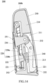
- the detachable side impact protection block 200 in a third embodiment of the present disclosure differs from that in the second embodiment only in that: a positioning mode of the first elastic member 240 is slightly different.
- the first locking member 220a is provided with a positioning protrusion 222
- the protection block 210 is provided with a positioning groove 213 corresponding to the positioning protrusion 222
- one end of the first elastic member 240 is sleeved on the positioning protrusion 222 and abuts against the first locking member 220a, and the other end thereof is accommodated in the positioning groove 213 and abuts against the protection block 210.
- the operating member 230 when the operating member 230 drives the first locking member 220a to pivot, it may press the first elastic member 240, and when the first elastic member 240 recovers its deformation, it may push the first locking member 220a to reset, and the driving part 232 may push the second locking member 220 to reset.
- detachable side impact protection block 200 in this embodiment are the same as those in the above-mentioned second embodiment, and thus will not be described again.
- the operating member 230 When the detachable side impact protection block 200 is installed on the side wing 100, the operating member 230 is pressed first to drive the first locking member 220a to pivot in a direction as indicated by an arrow F1 in FIG 13 , and the driving part 232 of the operating member 230 moves to push the second locking member 220b to pivot in a direction as indicated by an arrow F2 in FIG 13 , that is, pivoting directions of the first locking member 220a and the second locking member 220b are opposite to each other, so that the locking hooks 221 on these two locking members move to the first position and are received into the outer housing 250.
- the first elastic member 240 is compressed.
- the connecting end 200a of the outer housing 250 is connected to the accommodating groove 111.
- the first locking member 220a and the second locking member 220b are pivoted in opposite directions under the action of the first elastic member 240, so that the locking hooks 221 on these locking members are driven to move to the second position and snapped in the locking holes 112, and the force bearing ends 200b protrude from surfaces of the side wings 100, as shown in FIG 15 .
- the side impact protection block 200 pushes the cover 310 downwards and finally presses the cover 310 against the bottom of the accommodating groove 111, as shown in FIG 15 .
- the detachable side impact protection block 200 When the detachable side impact protection block 200 is detached, press the operating member 230 to drive the first locking member 220a and the second locking member 220b to pivot in the directions as indicated by arrows F1 and F2 in FIG 15 until the locking hooks 221 of both locking members are separated from the locking holes 112. At this time, the detachable side impact protection block 200 may be detached from the fixing seat 110. After the detachable side impact protection block 200 is separated from the fixing seat 110, the cover 310 is reset under the action of the second elastic member 320, so as to shield the accommodating groove 111 of the fixing seat 110, as shown in FIG 16 .
- the detachable side impact protection block 200 also includes two locking members 220, but the connection mode between the operating member 230 and the locking member 220 in this embodiment is different from that in the above-mentioned second and third embodiments.
- the two locking members 220 have the same structure and are pivotally connected to the protection block 210 symmetrically.
- the locking member 220 and the locking hook 221 have a separated structure.
- the approximate middle section of the locking member 220 is pivotally connected to the protection block 210
- the lower end of the locking member 220 is pivotally connected to the locking hook 221, which is slidably connected to the protection block 210
- the upper end of the locking member 220 abuts against the operating member 230.
- the locking member 220 may be driven to pivot to make the locking hook 221 slide between the first position and the second position along the protection block 210.
- a driving part 232 and a driven part 223 are cooperated with each other and are arranged between the operating member 230 and the locking member 220, and the driving part 232 and the driven part 223 may interact with each other to push the locking member 220 to pivot when the operating member 230 is forced to move. More specifically, one end of the operating member 230 is connected to the protection block 210, and the other end thereof is provided with a driving part 232 protruding in a direction parallel to an axial direction of the pivoting axis of the locking member 220, and the side surface of the driving part 232 forms a driving surface 2321.
- the upper end of the locking member 220 is convexly provided with a driven part 223, the driven part 223 and the locking hook 221 respectively protrude in opposite directions relative to a body of the locking member 220, and the driven part 223 is provided with a driven inclined surface 2231, an extending direction of which is staggered with the protruding direction of the driving part 232.
- the operating member 230 is forced to move, its driving part 232 moves along the driven inclined surface 2231, and the driving surface 2321 gradually acts on the driven inclined surface 2231 to push the locking member 220 to pivot.
- the driven parts 223 thereof are adjacent to each other, and the driven inclined surfaces 2231 of the two driven parts 223 are formed in a roughly V-shape.
- the driving surface 2321 acts on the driven inclined surfaces 2231, the two driven parts 22 are pushed to move to both sides of the driving part 232, thereby pushing the pivot of the two locking members 220.
- the protection block 210 is provided with an installing groove 211, a pivoting hole 214, a sliding groove 215 and an installing hole 216 which communicate with the installing groove 211 are provided on the side wall of the protection block 210.
- the locking member 220 is accommodated in the installing groove 211 and pivotally connected to the pivoting hole 214, and the locking hook 221 is slidably connected to the sliding groove 215 and pivotally connected to a lower end of the locking member 220.
- the operating member 230 is movably installed in the installing hole 216, and the driving part 232 thereof abuts against the driven inclined surface 2231 of the locking member 220.
- the first elastic member 240 abuts between the two locking hooks 221.
- one end of each of the locking hooks 221 is provided with a positioning groove, and the end of the first elastic member 240 is accommodated in the positioning groove.
- the first elastic member 240 may be pressed to be deformed, and when the first elastic member 240 is recovered, it can push the two locking hooks 221 to slide in opposite directions until they reach the first position.
- connection mode between the operating member 230 and the locking member 220 in this embodiment is also applicable to the case where only one locking member 220 is provided.
- the structure of the outer housing 250 in this embodiment is the same as that in the second and third embodiments, and the structure of the shielding assembly 300 is the same as that in the first embodiment, which will not be described again.
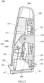
- the detachable side impact protection block 200 When the detachable side impact protection block 200 is installed on the side wing 100, press the operating member 230 first to drive the two locking members 220a to pivot in the directions as shown by arrows F3 and F4 in FIG 18 , that is, pivoting directions of the two locking members 220 are opposite to each other, and thus the two locking hooks 221 are driven to slide to the first position and be received into the outer housing 250. In this process, the first elastic member 240 is compressed. Then, the connecting end 200a of the outer housing 250 is connected to the accommodating groove 111.
- the elastic force of the first elastic member 240 pushes the two locking hooks 221 to slide in opposite directions to the second positions and to be snapped into the locking holes 112, as shown in FIG 23 .
- the installation is completed.
- the cover 310 In the process of connecting the detachable side impact protection block 200 to the fixing seat 110, it pushes the cover 310 downwards and finally presses the cover 310 against the bottom of the accommodating groove 111, as shown in FIG 23 .
- the detachable side impact protection block 200 When it is necessary to detach the detachable side impact protection block 200, press the operating member 230 again to drive the two locking members 220 to pivot until the locking hooks 221 of the two locking members 220 are separated from the locking holes 112. At this time, the detachable side impact protection block 200 may be detached from the fixing seat 110. After the detachable side impact protection block 200 is separated from the fixing seat 110, the cover 310 is reset under the action of the second elastic member 320, thereby shielding the accommodating groove 111 of the fixing seat 110.
- the locking member 220 may also be a magnetic member provided in at least one of the protection block 210 and the fixing seat 110.
- the other one thereof is made of a material which can attract the magnetic members magnetically.
- the detachable side impact protection block 200 described in the above first to fourth embodiments may be additionally provided with a magnetic member, that is, a magnetic member provided on at least one of the protection block 210 and the fixing seat 110 in the above embodiment can strengthen the connection therebetween by magnetic adsorption.
- the detachable side impact protection block 200 of the present disclosure has a protection block 210 and at least one locking member 220.
- the protection block 210 is detachably connected to the side wing or/and the base of the child safety seat, and protrudes from the surface at a connected position in a connected state.
- Each of the locking members 220 is arranged between the protection block 210 and the child safety seat to lock and unlock the protection block on the child safety seat.
- the user can selectively install the protection block 210 on the base or/and at least one side wing 100 according to the use requirements, so that the child safety seat 1 has sufficient safety in use, and the detachable side impact protection block 200 may be detached when not in use, so that the child safety seat 1 occupies less lateral space and is more convenient to use or store.
- the child safety seat 1 with the detachable side impact protection block 200 also has the same technical effect.
Landscapes
- Engineering & Computer Science (AREA)
- Aviation & Aerospace Engineering (AREA)
- Transportation (AREA)
- Mechanical Engineering (AREA)
- Health & Medical Sciences (AREA)
- Child & Adolescent Psychology (AREA)
- General Health & Medical Sciences (AREA)
- Seats For Vehicles (AREA)
- Ladders (AREA)
Abstract
Description
- The present disclosure relates to the technical field of baby carriers, in particular to a child safety seat and a detachable side impact protection block suitable for the child safety seat.
- A child safety seat is a device configured to protect a baby in a vehicle seat, and restraints the baby by a restraint device. In the occurrence of emergency braking or accidental collision, an impact force on the baby can be reduced through a housing of the child safety seat, and the movement of the baby's body can be retrained through the restraint device, so that the probability of injury on the baby in the accident can be reduced and the riding safety of the children can be ensured.
- Generally, each of side wings of the child safety seat is provided with a side collision protective structure protruded laterally. In the occurrence of side collision of the vehicle, the side wings of the child safety seat and the side collision protective structures thereon perform a buffering function to protect the body and head of the child. However, the side collision protective structures arranged on the side wings occupy much more lateral space, which is inconvenient for the storage of the child safety seat.
- Therefore, it is necessary to provide a detachable side impact protection block which can be selectively installed by users according to the requirements.
- An object of the present disclosure is to provide a detachable side impact protection block, which can be selectively installed by users according to the requirements.
- Another object of the present disclosure is to provide a child safety seat having a detachable side impact protection block.
- In order to achieve the above objects, the technical solution of the present disclosure is as follows: a detachable side impact protection block is provided, which is detachably installed on the side wing of a child safety seat and includes a protection block and at least one locking member. The protection block is detachably connected to the child safety seat and protrudes from a surface at a connected position in a connected state. Each of the at least one locking member is arranged between the protection block and the child safety seat for locking and unlocking the protection block on the child safety seat.
- Preferably, the at least one locking member is a magnetic member provided on at least one of the protection block and the child safety seat, and the protection block is attracted to the child safety seat through the magnetic member.
- Preferably, each of the at least one locking member is movably connected to the protection block and is movable between a locked position and an unlocked position, and the at least one locking member is configured to be detachably engaged with the child safety seat.
- Preferably, each of the at least one locking member has at least one locking hook, and each of the at least one locking hook has a first position and a second position opposite to each other, the at least one locking hook protrudes out of the protection block when it is at the first position, and the at least one locking hook is received into the protection block when it is at the second position.
- Preferably, when the at least one locking hook is at the first position, it is engaged with the child safety seat to connect the protection block to the child safety seat, and when the at least one locking hook is at the second position, the protection block is movable relative to the child safety seat.
- Preferably, the detachable side impact protection block includes a plurality of said locking members, and the locking hooks of the locking members are arranged on opposite sides of the protection block.
- Preferably, a bottom end of the protection block is symmetrically arranged along a central line in a widthwise direction, and the locking hooks of the locking members are arranged at the bottom end of the protection block and positioned on both sides of the central line.
- Preferably, the detachable side impact protection block further includes a first elastic member installed on the protection block and abutting against the at least one locking member or an operating member, and the first elastic member permits the at least one locking hook to have a tendency of moving to the first position.
- Preferably, the at least one locking member or the operating member is provided with a positioning structure, and one end of the first elastic member is installed on the positioning structure and abuts against the positioning structure.
- Preferably, the positioning structure is a positioning protrusion or a positioning groove.
- Preferably, the protection block is provided with an installing groove, the at least one locking member is accommodated in the installing groove and pivotally connected to the protection block, and the at least one locking member is capable of driving the at least one locking hook to move between the first position and the second position when pivoting.
- Preferably, the at least one locking hook is pivotally connected to one end of the at least one locking member and slidably connected to the protection block.
- Preferably, the at least one locking hook is fixed to one end of the at least one locking member.
- Preferably, the detachable side impact protection block further includes an operating member connected to the at least one locking member for driving the at least one locking member to move to the unlocked position and be disengaged from the child safety seat.
- Preferably, the operating member is fixed to the at least one locking member and exposed out of the protection block, and the operating member drives the at least one locking member to move when it is forced.
- Preferably, the operating member further includes a driving part connected to another said locking member, and the operating member is capable of driving each of the locking members to move synchronously between the locking position and the unlocking position when the operating member moves.
- Preferably, a driving surface and a driven inclined surface cooperates with each other and are arranged between the operating member and the at least one locking member, and the driving surface and the driven inclined surface interact with each other to push the at least one locking member to pivot when the operating member is forced.
- Preferably, the operating member is convexly provided with a driving part, a side surface of the driving part forms the driving surface, and the driven inclined surface is arranged at one end of the at least one locking member and abuts against the driving surface.
- Preferably, the detachable side impact protection block further includes an outer housing covering the protection block and exposing the operating member from the outer housing, and the at least one locking member movably protrudes out of the outer housing to be engaged with the child safety seat.
- Correspondingly, the present disclosure also provides a child safety seat, which includes a base, a seat body arranged on the base, two side wings arranged on the seat body, and the detachable side impact protection block as mentioned above, wherein the detachable side impact protection block is detachably connected to the base or/and at least one of the two said side wings.
- Preferably, each of the side wing and the base is respectively provided with an accommodating groove, the protection block is detachably connected into the accommodating groove, and the protection block protrudes from a surface of the side wing or the base in the connected state.
- Preferably, a shape of the accommodating groove corresponds to a shape of a connecting end of the detachable side impact protection block, and a depth of the accommodating groove is greater than 1cm.
- Preferably, the child safety seat further includes a fixing seat fixed to the side wing or the base, the fixing seat is provided with the accommodating groove and a locking hole communicating with the accommodating groove, and the at least one locking member is detachably engaged with the locking hole.
- Preferably, wherein each one of the two opposite side walls of the accommodating groove is provided with a plurality of said locking holes, and the at least one locking member is capable of being engaged with at least one of the locking holes.
- Preferably, the child safety seat further includes a pop-up shielding assembly telescopically installed within the accommodating groove and is capable of being protruded from and retracted into the accommodating groove to shield the accommodating groove when the protection block is detached.
- Preferably, the shielding assembly includes a cover and a second elastic member. The cover is slidably connected to the fixing seat. When the protection block is installed in the accommodating groove, the cover is pressed into a bottom of the accommodating groove; and when the protection block is detached, the cover is capable of moving to a top of the accommodating groove to shield the accommodating groove. The second elastic member is accommodated in the accommodating groove and abuts against the cover, and the second elastic member permits the cover to have a tendency of moving towards the top of the accommodating groove.
- Preferably, a side of the cover is provided with a snapping hook slidably snapped in the locking hole.
- Compared with the prior art, the detachable side impact protection block of the present disclosure has a protection block and at least one locking member. The protection block is detachably connected to the child safety seat, and protrudes from the surface at a connected position in a connected state. Each of the locking members is arranged between the protection block and the child safety seat to lock and unlock the protection block on the child safety seat. Therefore, the user can selectively install the protection block on the base or/and at least one side wing according to the use requirements, so that the child safety seat has sufficient safety when in use, and the detachable side impact protection block may be detached when not in use, so that the child safety seat occupies less lateral space and thus is more convenient to use or store. Correspondingly, the child safety seat with the detachable side impact protection block also has the same technical effect.
-
-
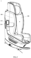
FIG 1 is a schematic structural view of a child safety seat of the present disclosure. -
FIG 2 is a schematic structural view of the detachable side impact protection block inFIG 1 after it is detached. -
FIG 3 is a schematic structural view ofFIG 1 from another angle. -
FIG 4 is a schematic structural view ofFIG 2 from another angle. -
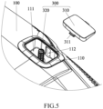
FIG 5 is a partial exploded view of a cover and a fixing seat inFIG 4 . -
FIG 6 is a schematic structural view of the fixing seat inFIG 5 from another angle. -
FIG 7 is a partial sectional view of the cover and the fixing seat inFIG 4 . -
FIG 8 is a schematic structural view of a detachable side impact protection block according to a first embodiment of the present disclosure. -
FIG 9 is an exploded view ofFIG 8 . -
FIG 10 is a sectional view of the detachable side impact protection block and a shielding assembly inFIG 8 . -
FIG 11 is a schematic structural view of a detachable side impact protection block according to a second embodiment of the present disclosure. -
FIG 12 is a schematic structural view ofFIG 11 from another angle. -
FIG 13 is a cross-sectional view ofFIG 11 . -
FIG 14 is a sectional view of a detachable side impact protection block according to a third embodiment of the present disclosure. -
FIG 15 is a sectional view of the detachable side impact protection block inFIG 14 installed on the side wing. -
FIG 16 is a state schematic view in which the detachable side impact protection block ofFIG 15 is detached. -
FIG 17 is a schematic structural view of a detachable side impact protection block according to a fourth embodiment of the present disclosure. -
FIG 18 is a sectional view ofFIG 17 . -
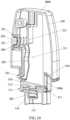
FIG 19 is an exploded view ofFIG 17 . -
FIG 20 is a further exploded view ofFIG 19 . -
FIG 21 is a schematic structural view ofFIG 20 from another angle. -
FIG 22 is a partial structural view of the detachable side impact protection block inFIG 17 installed on the side wing. -
FIG 23 is a partial sectional view taken along line A-A inFIG 22 . -
FIG 24 is a partial sectional view taken along line B-B inFIG 22 . - Embodiments of the present disclosure will be described below with reference to the accompanying drawings, in which the same element numbers in different figures represent the same elements.
- First, as shown in
FIGS. 1-4 , thechild safety seat 1 provided by the present disclosure has a seat body (not shown), twoside wings 100 oppositely arranged on the seat body, and a detachable sideimpact protection block 200 detachably installed on one or both of the twoside wings 100. When it is necessary, the detachable sideimpact protection block 200 may be selectively installed on at least oneside wing 100, and the installed detachable sideimpact protection block 200 protrudes from a surface of theside wing 100, as shown inFIGS. 1 and3 . In this way, when a side collision occurs, the detachable sideimpact protection block 200 may first collide with the vehicle body or other objects to buffer the impact force, thereby providing a better protection. When the detachable sideimpact protection block 200 is not needed, it may be detached from theside wing 100 to reduce the lateral space as occupied, as shown inFIGS. 2 and4 . - It should be understood that the detachable side
impact protection block 200 is not limited to be installed on theside wing 100. The sideimpact protection block 200 can also be installed at other positions on thechild safety seat 1. For example, in one embodiment, the detachable sideimpact protection block 200 may be optionally installed on a base, on which the seat body is installed. - Referring to
FIGS. 4-7 below, in thechild safety seat 1 of the present disclosure, a fixingseat 110 is fixed on each of theside wings 100. The fixingseat 110 is fixed on thecorresponding side wing 100 by screws or other connectors, a fixing way of which is not limited in the present disclosure. The fixingseat 110 is provided with anaccommodating groove 111 with a depth greater than 1 cm. The detachable sideimpact protection block 200 is detachably connected to (inserted into) theaccommodating groove 111 of the fixingseat 110, and protrudes from a surface of theside wing 100 in its connected state. - As shown in
FIGS. 8-12 ,14 and17 , one end of the detachable sideimpact protection block 200 forms a connectingend 200a, and the other end thereof forms aforce bearing end 200b. In addition, an inner diameter of theaccommodating groove 111 of the fixingseat 110 is greater than or equal to an outer diameter of the connectingend 200a, so as to ensure that the connectingend 200a can be detachably connected to theaccommodating groove 111, and theforce bearing end 200b protrudes from the surface of theside wing 100 in the connected state. - More preferably, the
accommodating groove 111 is shaped to correspond to a shape of the connectingend 200a, both of theaccommodating groove 111 and the connectingend 200a may be regular geometric shapes or irregular shapes, and the inner diameter of theaccommodating groove 111 is slightly greater than the outer diameter of the connectingend 200a, so that shaking of the sideimpact protection block 200 can be prevented after the connectingend 200a is connected to theaccommodating groove 111. In this way, the connection stability and better buffering for the impact force when the detachable sideimpact protection block 200 is collided are provided. - As shown in
FIGS. 4-7 , more preferably, alocking hole 112 communicating with theaccommodating groove 111 is formed on a side wall of the fixingseat 110, and the connectingend 200a of the detachable sideimpact protection block 200 may be detachably engaged with thelocking hole 112 after being connected to theaccommodating groove 111. In addition, lockingholes 112 may be respectively formed on opposite side walls of the fixingseat 110, and at least onelocking hole 112 may be formed on each of the side walls. This arrangement enables the detachable sideimpact protection block 200 to be connected to theaccommodating groove 111 and then snapped in the at least onelocking hole 112. This not only realizes the installation of the detachable sideimpact protection block 200 on both sides (as described later), but also makes its connection more convenient and stable. - As shown in
FIGS. 5-7 , in one embodiment of the present disclosure, alocking hole 112 is formed on each of side walls of the fixingseat 110 in a widthwise direction. Each of the side walls is provided with onelocking hole 112, and the locking holes 112 on both side walls are oppositely arranged, so that the detachable sideimpact protection block 200 can be selectively snapped in at least onelocking hole 112. - It should be noted that, in different embodiments of the present disclosure, the
child safety seat 1 may be different, but theside wings 100 and the fixingseat 110 are all arranged in the same way, and the structures of other parts are the conventional arrangements well known to those ordinary skilled in the art, and will not be described in detail. - Referring to
FIGS. 1-24 below, the detachable sideimpact protection block 200 provided by the present disclosure mainly includes aprotection block 210 and at least one lockingmember 220. Theprotection block 210 is detachably connected to theaccommodating groove 111, and the at least one lockingmember 220 is arranged between theprotection block 210 and the fixingseat 110 for locking or unlocking theprotection block 210 on the fixingseat 110. - In the preferred embodiment of the present disclosure, the detachable side
impact protection block 200 further includes an operatingmember 230 and a firstelastic member 240. Each lockingmember 220 may be pivotally connected to theprotection block 210 and movable between a locked position and an unlocked position, and the lockingmember 220 is used to be detachably engaged with thelocking hole 112. The operatingmember 230 is connected to the lockingmember 220 for driving the pivot of the lockingmember 220 to be changed between the locked position and the unlocked position, and the firstelastic member 240 is installed on theprotection block 210 and abuts against the lockingmember 220 or the operatingmember 230 to reset the lockingmember 220. When the detachable sideimpact protection block 200 is installed on theside wing 100, theprotection block 210 is connected to theaccommodating groove 111 of the fixingseat 110, the lockingmember 220 is snapped in thelocking hole 112 under the action of the firstelastic member 240 to be positioned, and the other end of theprotection block 210 protrudes from the surface of theside wing 100 and serves as a force bearing end during collision; and when the operatingmember 230 drives the lockingmember 220 to resist an acting force of the firstelastic member 240, the lockingmember 220 can be disengaged from the lockinghole 112, so that theprotection block 210 can be detached from the fixingseat 110, and then the entire detachable sideimpact protection block 200 can be detached. - More specifically, each locking
member 220 has at least onelocking hook 221, and thelocking hook 221 has a first position and a second position opposite to each other. When thelocking hook 221 is at the first position, it may protrude out of theprotection block 210, and at this time, the lockinghook 221 may be snapped in theaforementioned locking hole 112; and when thelocking hook 221 moves to the second position, it may be received into theprotection block 210, and at this time, theprotection block 210 may be movable relative to the fixingseat 110, so that theprotection block 210 is connected to theaccommodating groove 111 or detached from the fixingseat 110. In addition, the firstelastic member 240 permits thelocking hook 221 to have a tendency of 221 moving to the first position. - As shown in
FIGS. 5-24 , the detachable sideimpact protection block 200 of the present disclosure further includes anouter housing 250, which may cover theprotection block 210 and expose the operatingmember 230 and thelocking hook 221 from theouter housing 250. Theouter housing 250 can allow the detachable sideimpact protection block 200 to have a simple and beautiful appearance, and ensure the overall beauty of thechild safety seat 1 in use. - In different embodiments of the present disclosure, the structure of the detachable side
impact protection block 200 is slightly different. The different details of the detachable sideimpact protection block 200 in different embodiments will be explained with reference toFIGS. 7-24 below. - First referring to
FIGS. 8-10 , in a first embodiment of the present disclosure, the detachable sideimpact protection block 200 has a lockingmember 220 and alocking hook 221, and a lower end of theprotection block 210 forms the connectingend 200a, but it is not limited thereto. One end of the lockingmember 220 is pivotally connected to theprotection block 210, and thelocking hook 221 protrudes from the other end of the lockingmember 220 and is positioned at the connectingend 200a of theprotection block 210. The operatingmember 230 is coaxially pivoted with the lockingmember 220 and connected to the lockingmember 220. The operatingmember 230 protrudes out of theprotection block 210 and theouter housing 250. When the operatingmember 230 is forced to move, it may drive the lockingmember 220 to pivot, so that thelocking hook 221 is movable between the first position and the second position. In addition, at least one of theprotection block 210, the lockingmember 220 and the operatingmember 230 is provided with a positioning structure, and one end of the firstelastic member 240 is installed on and abuts against the positioning structure to ensure the installing stability of the firstelastic member 240. - More specifically, the operating
member 230 is fixed to the approximate middle section of the lockingmember 220 and protrudes out of theprotection block 210 and theouter housing 250, so that the operatingmember 230 directly drives the lockingmember 220 to pivot when it is forced. More preferably, the operatingmember 230, the lockinghook 221 and the lockingmember 220 are integrally formed, but it is not limited thereto, and the operatingmember 230 and thelocking hook 221 may be separately formed and then fixed to the lockingmember 220. - As shown in
FIGS. 9-10 , theprotection block 210 is provided with an installinggroove 211, the lockingmember 220 is accommodated within the installinggroove 211, and an upper end of the lockingmember 220 is pivotally connected to theprotection block 210. Also, the operatingmember 230 and theprotection block 210 are respectively provided with a positioning structure. The positioning structure is preferably a positioning protrusion. Specifically, a side surface of the operatingmember 230 is provided with apositioning protrusion 231. Anotherpositioning protrusion 212 directly facing thepositioning protrusion 231 is arranged on a side wall of the installinggroove 211, and two ends of the firstelastic member 240 are sleeved on the twopositioning protrusions member 230 and theprotection block 210 respectively. Therefore, when the operatingmember 230 is forced to drive the pivot of the lockingmember 220, the firstelastic member 240 may be compressed for deformation, and after the operatingmember 230 is released, the firstelastic member 240 may recover its deformation and drive the operatingmember 230 to reset the lockingmember 220. - It should be understood that the locking
member 220 is provided with a positioning protrusion, so that an end of the firstelastic member 240 abuts against the lockingmember 220, and the lockingmember 220 may also be reset. In addition, the positioning structure is not limited to the positioning protrusion, for example, it may also be provided as a positioning groove or other structures. - Referring to
FIGS. 5-10 again, in this embodiment, the connectingend 200a of theprotection block 210 is symmetrically arranged along a central line M in a widthwise direction, and thelocking hook 221 is positioned at the connectingend 200a and protrudes from a side surface of the connectingend 200a in the widthwise direction, as shown inFIG 8 . Correspondingly, a shape of theaccommodating groove 111 of the fixingseat 110 corresponds to a shape of the connectingend 200a, an inner diameter of theaccommodating groove 111 is slightly greater than an outer diameter of the connectingend 200a, and each of two side walls of the fixingseat 110 in the widthwise direction is provided with alocking hole 112. In this way, by connecting thelocking hook 221 to any of the locking holes 112, theprotection block 210 may be connected to theaccommodating groove 111 and thelocking hook 221 may be engaged with thelocking hole 112, so that theprotection block 210 can be installed in a way of a front side or a back side thereof, and thus it is more convenient for the installation of the detachable sideimpact protection block 200. - It should be understood that the detachable side
impact protection block 200 in this embodiment may also be provided with two ormore locking members 220. For example, two lockingmembers 220 are pivotally connected to theprotection block 210, and the locking hooks 221 of the two lockingmembers 220 are respectively provided on the two side surfaces of the connectingend 200a in the widthwise direction, as such, theprotection block 210 can also be installed by the way of the front side or the back side thereof, and both side surfaces of theprotection block 210 are snapped to the fixingseat 110 after installation, providing more stable connection. It should be understood that, when a plurality of lockingmembers 220 are provided, the lockingmembers 220 are distributed on both sides of the central line M and the locking hooks 221 are respectively positioned on both side surfaces of the connectingend 200a in the widthwise direction, as long as the number of lockingholes 112 on the fixingseat 110 corresponds to that of the locking hooks 221. - As shown in
FIGS. 8-10 , a first throughhole 251 is formed on theouter housing 250 at a position corresponding to the operatingmember 230. After theouter housing 250 covers theprotection block 210, the operatingmember 230 is exposed out of theouter housing 250 through the first throughhole 251. In addition, in this embodiment, a bottom edge of theouter housing 250 is positioned above thelocking hook 221 after being sleeved on theprotection block 210, that is, the connectingend 200a protrudes out of theouter housing 250, so that the bottom edge of theouter housing 250 just abuts against an outer edge of the fixingseat 110 after the connectingend 200a is connected to theaccommodating groove 111, as shown inFIG 3 , the aesthetic connection can be ensured. The top end of thehousing 250 forms aforce bearing end 200b. Of course, theprotection block 210 may also be completely accommodated in theouter housing 250. At this time, the bottom end of theouter housing 250 forms the connectingend 200a to be connected to theaccommodating groove 111, and a second through hole is formed on theouter housing 250 at a position corresponding to thelocking hook 221, so that thelocking hook 221 movably protrudes out of theouter housing 250 through the second through hole to be engaged with the fixingseat 110. - In conjunction with
FIGS. 2-10 again, thechild safety seat 1 of the present disclosure further includes a pop-upshielding assembly 300. As shown inFIGS. 2 ,4 and6 , the pop-upshielding assembly 300 is installed within and can be protruded from and retracted into theaccommodating groove 111 to shield theaccommodating groove 111 when theprotection block 210 is detached, so as to maintain uniformity and aesthetics of the overall appearance of theside wing 100. - As shown in
FIGS. 5-7 , the shieldingassembly 300 includes acover 310 and a secondelastic member 320. A shape of thecover 310 is the same as the shape of theaccommodating groove 111, and a size of thecover 310 is slightly smaller than an inner diameter of theaccommodating groove 111. Thecover 310 is slidably installed in theaccommodating groove 111, and the secondelastic member 320 abuts against the bottom wall of theaccommodating groove 111 and thecover 310. When theprotection block 210 is installed in theaccommodating groove 111, thecover 310 is pressed into the bottom of theaccommodating groove 111. When theprotection block 210 is detached, thecover 310 moves to the top of theaccommodating groove 111 under the action of the secondelastic member 320 to shield theaccommodating groove 111. - More specifically, a side of the
cover 310 is provided with a snappinghook 311, and thecover 310 is slidably engaged with the fixingseat 110 through the snappinghook 311. In this embodiment, a side of thecover 310 corresponding to thelocking hole 112 is provided with a snappinghook 311, and thesnapping hook 311 of thecover 310 is slidably engaged in thelocking hole 112 to realize sliding connection, thus simplifying the structure of the fixingseat 110. When theprotection block 210 is installed in theaccommodating groove 111, it may push thecover 310 to slide towards the bottom of theaccommodating groove 111. In this process, the secondelastic member 320 is compressed to deform and generate an elastic force. After thelocking hook 221 is snapped in thelocking hole 112, the elastic force of the secondelastic member 320 may always push thecover 310 and theprotection block 210 upwards, so that theprotection block 210 is stably snapped in thelocking hole 112. - As shown in
FIG 7 , a bottom wall of theaccommodating groove 111 is concavely provided with apositioning groove 113, and correspondingly, thecover 310 is convexly provided with apositioning protrusion 312. One end of the secondelastic member 320 is accommodated in thepositioning groove 113, and the other end of the secondelastic member 320 is sleeved on thepositioning protrusion 312 and abuts against thecover 310. Of course, it is also possible to provide a positioning protrusion on the bottom wall of theaccommodating groove 111, or to provide a positioning groove on thecover 310. - With reference to
FIGS. 1-10 , an installation and disassembly principle of the detachable sideimpact protection block 200 in this embodiment will be explained. - To install the detachable side
impact protection block 200 on aside wing 100 of thechild safety seat 1, the operatingmember 230 is first pressed to drive the pivot of the lockingmember 220, so that thelocking hook 221 moves to the first position and is received into theprotection block 210. In this process, the firstelastic member 240 is compressed. Then, align thelocking hook 221 on theprotection block 210 to thelocking hole 112 of theaccommodating groove 111. After the operatingmember 230 is released, the lockingmember 220 is pivoted and reset under the action of the firstelastic member 240, so that thelocking hook 221 is snapped in thelocking hole 112. After that, the installation is completed. At this time, theforce bearing end 200b of the detachable sideimpact protection block 200 protrudes from the surface of theside wing 100, as shown inFIGS. 1 and3 . In the above manner, the detachable sideimpact protection block 200 is installed on at least oneside wing 100 of thechild safety seat 1 as desired. - In the process of connecting the detachable side
impact protection block 200 to the fixingseat 110, it pushes thecover 310 to slide towards the bottom of the fixingseat 110. After theprotection block 210 is snapped in thelocking hole 112, thecover 310 is pressed against the bottom of the fixingseat 110. Meanwhile, an elastic force generated by compression of the secondelastic member 320 always pushes thecover 310 upwards, so that theprotection block 210 is stably snapped in thelocking hole 112. - When it is required to detach the detachable side
impact protection block 200 from theside wing 100 of thechild safety seat 1, the operatingmember 230 is first pressed to drive the pivot of the lockingmember 220, so that thelocking hook 221 is disengaged from the lockinghole 112 and thelocking hook 221 moves to the second position. At this time, the detachable sideimpact protection block 200 may be detached from the fixingseat 110. After theprotection block 210 is detached, thecover 310 slides upwards under an elastic force of the secondelastic member 320 until the snappinghook 311 of thecover 310 abuts against an end wall of thelocking hole 112, and thecover 310 shields theaccommodating groove 111 of the fixingseat 110 to keep theside wing 100 clean and beautiful, as shown inFIGS. 4 and6 . - The detachable side
impact protection block 200 of the present disclosure is not limited to the embodiment with one lockingmember 220. A preferred embodiment with two lockingmembers 220 will be described below. - As shown in
FIGS. 10-13 , compared to the first embodiment, the detachable sideimpact protection block 200 in a second embodiment of the present disclosure has the following differences. The detachable sideimpact protection block 200 includes two lockingmembers 220, the two lockingmembers 220 are respectively pivotally connected to the installinggrooves 211 of theprotection block 210, and the locking hooks 221 are positioned on opposite sides of theprotection block 210, and the operatingmember 230 is connected to the two lockingmembers 220 to synchronously drive the two lockingmembers 220 to pivotally unlock, that is, the locking hooks 221 of two lockingmember 220 are driven to be synchronously movable between the first position and the second position. In addition, in this embodiment, thefirst locking member 220 and thesecond locking member 220 are driven by a firstelastic member 240 to synchronously move and reset. - For easy description, the two locking
members 220 are further described as afirst locking member 220a and asecond locking member 220b, respectively. One end of thefirst locking member 220a is pivotally connected to theprotection block 210, and the other end of thefirst locking member 220a is provided with alocking hook 221 protruding from a side surface of theprotection block 210 in the widthwise direction. The approximate middle section of thesecond locking member 220b is pivotally connected to theprotection block 210, and one end of thesecond locking member 220b is provided with alocking hook 221 protruding from the other side surface of theprotection block 210 in the widthwise direction. Preferably, the two lockinghooks 221 are arranged symmetric to the central line M of theprotection block 210 in the widthwise direction. Meanwhile, the operatingmember 230 is coaxially pivotally connected with thefirst locking member 220a and protrudes out of theprotection block 210. The operatingmember 230 is connected to thefirst locking member 220a and thesecond locking member 220b, and when the operatingmember 230 is forced to move, it may drive thefirst locking member 220a and thesecond locking member 220b to pivot synchronously. - With continued reference to
FIGS. 10-13 , the operatingmember 230 is fixed to the approximate middle section of thefirst locking member 220a or integrally formed with thefirst locking member 220a, and the operatingmember 230 also includes a drivingpart 232 protruding towards thesecond locking member 220b and pivotally connected to an end of thesecond locking member 220b away from the lockinghook 221, so that when the operatingmember 230 is pressed, it drives the pivot of thefirst locking member 220a and moves the drivingpart 232. When the drivingpart 232 moves, it may push the upper end of thesecond locking member 220b, and thus rotates thesecond locking member 220b around its pivot axis, wherein a pivoting direction of thesecond locking member 220b is opposite to a pivoting direction of thefirst locking member 220a, that is, to drive thefirst locking member 220a and thesecond locking member 220b to move toward each other, so that the locking hooks 221 on thefirst locking member 220a and thesecond locking member 220b synchronously move to the second position. After the operatingmember 230 is released, thefirst locking member 220a and thesecond locking member 220b synchronously move and reset under the action of the firstelastic member 240. - In this embodiment, the arrangement of the
second locking member 220b simplifies its structure. Of course, thesecond locking member 220b may be arranged in the same structure as thefirst locking member 220a, which does not affect the engagement thereof with the fixingseat 110. - With further reference to
FIGS. 10-13 , in this embodiment, thefirst locking member 220a and thesecond locking member 220b are respectively provided with apositioning protrusion 222. Specifically, thepositioning protrusion 222 on thesecond locking member 220b is arranged below its pivoting shaft, and thepositioning protrusion 222 on thefirst locking member 220a is directly opposite to that on thesecond locking member 220b. Two ends of the firstelastic member 240 are respectively sleeved on the twopositioning protrusions 222 and abut against thefirst locking member 220a and thesecond locking member 220b, so that in the process of pivoting thefirst locking member 220a and thesecond locking member 220b to the unlocked positions thereof, they gradually approach and compress the firstelastic member 240 to be deformed. After the operatingmember 230 is released, the firstelastic member 240 is recovered to reset thefirst locking member 220a and thesecond locking member 220b synchronously. - It should be understood that, two first
elastic members 240 are provided so that they abut against thefirst locking member 220a and thesecond locking member 220b, respectively, and thefirst locking member 220a and thesecond locking member 220b can be reset. - Referring to
FIG 12 again, in this embodiment, a bottom end of theprotection block 210 is symmetrically arranged along the central line M thereof in the widthwise direction, and a regular geometric shape is formed on the bottom end of theprotection block 210, so that the detachable sideimpact protection block 200 can be engaged more smoothly by the way of the front and back sides thereof. - Referring to
FIGS. 10-13 again, the arrangement of theouter housing 250 in this embodiment is slightly different from that in the first embodiment. Specifically, a bottom edge of theouter housing 250 abuts against a bottom edge of theprotection block 210, that is, theprotection block 210 is completely received in theouter housing 250, a connectingend 200a is formed on the bottom end of theouter housing 250, the shape and size of the bottom end of theouter housing 250 correspond to that of theaccommodating groove 111 of the fixingseat 110, and aforce bearing end 200b is formed on the top end of theouter housing 250. Meanwhile, thehousing 250 is provided with a first throughhole 251 and a second throughhole 252. The operatingmember 230 is exposed out of theouter housing 250 through the first throughhole 251, and thelocking hook 221 movably protrudes out of theouter housing 250 through the second throughhole 252. - In this embodiment, other parts of the detachable side
impact protection block 200 and the structure of the shieldingassembly 300 are the same as those in the first embodiment, and thus will not be described again. - Referring to
FIGS. 14-16 , the detachable sideimpact protection block 200 in a third embodiment of the present disclosure differs from that in the second embodiment only in that: a positioning mode of the firstelastic member 240 is slightly different. In this embodiment, thefirst locking member 220a is provided with apositioning protrusion 222, and theprotection block 210 is provided with apositioning groove 213 corresponding to thepositioning protrusion 222, and one end of the firstelastic member 240 is sleeved on thepositioning protrusion 222 and abuts against thefirst locking member 220a, and the other end thereof is accommodated in thepositioning groove 213 and abuts against theprotection block 210. Thus, when the operatingmember 230 drives thefirst locking member 220a to pivot, it may press the firstelastic member 240, and when the firstelastic member 240 recovers its deformation, it may push thefirst locking member 220a to reset, and the drivingpart 232 may push thesecond locking member 220 to reset. - Other parts and the structure of the detachable side
impact protection block 200 in this embodiment are the same as those in the above-mentioned second embodiment, and thus will not be described again. - With reference to
FIGS. 11-16 , an installation and disassembly principle of the detachable sideimpact protection block 200 in the second and third embodiments will be explained below. - When the detachable side
impact protection block 200 is installed on theside wing 100, the operatingmember 230 is pressed first to drive thefirst locking member 220a to pivot in a direction as indicated by an arrow F1 inFIG 13 , and the drivingpart 232 of the operatingmember 230 moves to push thesecond locking member 220b to pivot in a direction as indicated by an arrow F2 inFIG 13 , that is, pivoting directions of thefirst locking member 220a and thesecond locking member 220b are opposite to each other, so that the locking hooks 221 on these two locking members move to the first position and are received into theouter housing 250. In this process, the firstelastic member 240 is compressed. Then, the connectingend 200a of theouter housing 250 is connected to theaccommodating groove 111. After the operatingmember 230 is released, thefirst locking member 220a and thesecond locking member 220b are pivoted in opposite directions under the action of the firstelastic member 240, so that the locking hooks 221 on these locking members are driven to move to the second position and snapped in the locking holes 112, and the force bearing ends 200b protrude from surfaces of theside wings 100, as shown inFIG 15 . In the process of connecting the detachable sideimpact protection block 200 to the fixingseat 110, the sideimpact protection block 200 pushes thecover 310 downwards and finally presses thecover 310 against the bottom of theaccommodating groove 111, as shown inFIG 15 . - When the detachable side
impact protection block 200 is detached, press the operatingmember 230 to drive thefirst locking member 220a and thesecond locking member 220b to pivot in the directions as indicated by arrows F1 and F2 inFIG 15 until the locking hooks 221 of both locking members are separated from the locking holes 112. At this time, the detachable sideimpact protection block 200 may be detached from the fixingseat 110. After the detachable sideimpact protection block 200 is separated from the fixingseat 110, thecover 310 is reset under the action of the secondelastic member 320, so as to shield theaccommodating groove 111 of the fixingseat 110, as shown inFIG 16 . - Referring to
FIGS. 17- 24 , in a fourth embodiment of the present disclosure, the detachable sideimpact protection block 200 also includes two lockingmembers 220, but the connection mode between the operatingmember 230 and the lockingmember 220 in this embodiment is different from that in the above-mentioned second and third embodiments. - Referring to
FIGS. 17-21 , in this embodiment, the two lockingmembers 220 have the same structure and are pivotally connected to theprotection block 210 symmetrically. The lockingmember 220 and thelocking hook 221 have a separated structure. Take one of the lockingmembers 220 as an example, the approximate middle section of the lockingmember 220 is pivotally connected to theprotection block 210, the lower end of the lockingmember 220 is pivotally connected to thelocking hook 221, which is slidably connected to theprotection block 210, and the upper end of the lockingmember 220 abuts against the operatingmember 230. When the operatingmember 230 moves, the lockingmember 220 may be driven to pivot to make thelocking hook 221 slide between the first position and the second position along theprotection block 210. - As shown in
FIGS. 17-21 , in this embodiment, a drivingpart 232 and adriven part 223 are cooperated with each other and are arranged between the operatingmember 230 and the lockingmember 220, and the drivingpart 232 and the drivenpart 223 may interact with each other to push the lockingmember 220 to pivot when the operatingmember 230 is forced to move. More specifically, one end of the operatingmember 230 is connected to theprotection block 210, and the other end thereof is provided with a drivingpart 232 protruding in a direction parallel to an axial direction of the pivoting axis of the lockingmember 220, and the side surface of the drivingpart 232 forms adriving surface 2321. Correspondingly, the upper end of the lockingmember 220 is convexly provided with adriven part 223, the drivenpart 223 and thelocking hook 221 respectively protrude in opposite directions relative to a body of the lockingmember 220, and the drivenpart 223 is provided with a driveninclined surface 2231, an extending direction of which is staggered with the protruding direction of the drivingpart 232. When the operatingmember 230 is forced to move, its drivingpart 232 moves along the driveninclined surface 2231, and thedriving surface 2321 gradually acts on the driveninclined surface 2231 to push the lockingmember 220 to pivot. - As shown in
FIGS. 20-21 , in this embodiment, after the two lockingmembers 220 are pivotally connected to theprotection block 210, the drivenparts 223 thereof are adjacent to each other, and the driveninclined surfaces 2231 of the two drivenparts 223 are formed in a roughly V-shape. When thedriving surface 2321 acts on the driveninclined surfaces 2231, the two driven parts 22 are pushed to move to both sides of the drivingpart 232, thereby pushing the pivot of the two lockingmembers 220. - Further referring to
FIGS. 17-21 , in this embodiment, theprotection block 210 is provided with an installinggroove 211, a pivotinghole 214, a slidinggroove 215 and an installing hole 216 which communicate with the installinggroove 211 are provided on the side wall of theprotection block 210. The lockingmember 220 is accommodated in the installinggroove 211 and pivotally connected to thepivoting hole 214, and thelocking hook 221 is slidably connected to the slidinggroove 215 and pivotally connected to a lower end of the lockingmember 220. The operatingmember 230 is movably installed in the installing hole 216, and the drivingpart 232 thereof abuts against the driveninclined surface 2231 of the lockingmember 220. - In this embodiment, the first
elastic member 240 abuts between the two locking hooks 221. Specifically referring toFIG 18 , one end of each of the locking hooks 221 is provided with a positioning groove, and the end of the firstelastic member 240 is accommodated in the positioning groove. When the two lockinghooks 221 slide towards each other, the firstelastic member 240 may be pressed to be deformed, and when the firstelastic member 240 is recovered, it can push the two lockinghooks 221 to slide in opposite directions until they reach the first position. - It should be understood that, the connection mode between the operating
member 230 and the lockingmember 220 in this embodiment is also applicable to the case where only one lockingmember 220 is provided. - In addition, the structure of the
outer housing 250 in this embodiment is the same as that in the second and third embodiments, and the structure of the shieldingassembly 300 is the same as that in the first embodiment, which will not be described again. - Hereinafter, with reference to
FIGS. 17-24 , an installation and disassembly principle of the detachable sideimpact protection block 200 in this embodiment will be explained. - When the detachable side
impact protection block 200 is installed on theside wing 100, press the operatingmember 230 first to drive the two lockingmembers 220a to pivot in the directions as shown by arrows F3 and F4 inFIG 18 , that is, pivoting directions of the two lockingmembers 220 are opposite to each other, and thus the two lockinghooks 221 are driven to slide to the first position and be received into theouter housing 250. In this process, the firstelastic member 240 is compressed. Then, the connectingend 200a of theouter housing 250 is connected to theaccommodating groove 111. After the operatingmember 230 is released, the elastic force of the firstelastic member 240 pushes the two lockinghooks 221 to slide in opposite directions to the second positions and to be snapped into the locking holes 112, as shown inFIG 23 . After that, the installation is completed. In the process of connecting the detachable sideimpact protection block 200 to the fixingseat 110, it pushes thecover 310 downwards and finally presses thecover 310 against the bottom of theaccommodating groove 111, as shown inFIG 23 . - When it is necessary to detach the detachable side
impact protection block 200, press the operatingmember 230 again to drive the two lockingmembers 220 to pivot until the locking hooks 221 of the two lockingmembers 220 are separated from the locking holes 112. At this time, the detachable sideimpact protection block 200 may be detached from the fixingseat 110. After the detachable sideimpact protection block 200 is separated from the fixingseat 110, thecover 310 is reset under the action of the secondelastic member 320, thereby shielding theaccommodating groove 111 of the fixingseat 110. - It should be understood that the structure of the detachable side
impact protection block 200 of the present disclosure is not limited to the arrangement mode in the above preferred embodiments. In other embodiments, the lockingmember 220 may also be a magnetic member provided in at least one of theprotection block 210 and the fixingseat 110. When only one of theprotection block 210 and the fixingseat 110 is provided with a magnetic member, the other one thereof is made of a material which can attract the magnetic members magnetically. After theprotection block 210 is connected to theaccommodating groove 111, it is magnetically attracted to the fixingseat 110. In this way, the installation of theprotection block 210 can be realized without providing thelocking hole 112 on the fixingseat 110. - Furthermore, the detachable side
impact protection block 200 described in the above first to fourth embodiments may be additionally provided with a magnetic member, that is, a magnetic member provided on at least one of theprotection block 210 and the fixingseat 110 in the above embodiment can strengthen the connection therebetween by magnetic adsorption. - As mentioned above, the detachable side
impact protection block 200 of the present disclosure has aprotection block 210 and at least one lockingmember 220. Theprotection block 210 is detachably connected to the side wing or/and the base of the child safety seat, and protrudes from the surface at a connected position in a connected state. Each of the lockingmembers 220 is arranged between theprotection block 210 and the child safety seat to lock and unlock the protection block on the child safety seat. Therefore, the user can selectively install theprotection block 210 on the base or/and at least oneside wing 100 according to the use requirements, so that thechild safety seat 1 has sufficient safety in use, and the detachable sideimpact protection block 200 may be detached when not in use, so that thechild safety seat 1 occupies less lateral space and is more convenient to use or store. - Correspondingly, the
child safety seat 1 with the detachable sideimpact protection block 200 also has the same technical effect. - What has been disclosed above is only the preferred embodiment of the present disclosure, which of course should not be used to limit the scope of the present disclosure. Therefore, equivalent changes made according to the scope of the present disclosure are still covered by the present disclosure.
Claims (27)
- A detachable side impact protection block detachably installed on a child safety seat, comprising:a protection block detachably connected to the child safety seat and protruding from a surface at a connected position in a connected state;at least one locking member, each of the at least one locking member being arranged between the protection block and the child safety seat for locking and unlocking the protection block on the child safety seat.
- The detachable side impact protection block according to claim 1, wherein the at least one locking member is a magnetic member provided on at least one of the protection block and the child safety seat, and the protection block is attracted to the child safety seat through the magnetic member.
- The detachable side impact protection block according to claim 1, wherein each of the at least one locking member is movably connected to the protection block and is movable between a locked position and an unlocked position, and the at least one locking member is configured to be detachably engaged with the child safety seat.
- The detachable side impact protection block according to claim 3, wherein each of the at least one locking member has at least one locking hook, and each of the at least one locking hook has a first position and a second position opposite to each other, the at least one locking hook protrudes out of the protection block when it is at the first position, and the at least one locking hook is received into the protection block when it is at the second position.
- The detachable side impact protection block according to claim 4, wherein when the at least one locking hook is at the first position, it is engaged with the child safety seat to connect the protection block to the child safety seat, and when the at least one locking hook is at the second position, the protection block is movable relative to the child safety seat.
- The detachable side impact protection block according to claim 4, comprising a plurality of said locking members, the locking hooks of the locking members being arranged on opposite sides of the protection block.
- The detachable side impact protection block according to claim 6, wherein a bottom end of the protection block is symmetrically arranged along a central line in a widthwise direction, and the locking hooks of the locking members are arranged at the bottom end of the protection block and positioned on both sides of the central line.
- The detachable side impact protection block according to claim 4, further comprising a first elastic member installed on the protection block and abutting against the at least one locking member or an operating member, the first elastic member permitting the at least one locking hook to present a tendency of moving to the first position.
- The detachable side impact protection block according to claim 8, wherein the at least one locking member or the operating member is provided with a positioning structure, and one end of the first elastic member is installed on the positioning structure and abuts against the positioning structure.
- The detachable side impact protection block according to claim 9, wherein the positioning structure is a positioning protrusion or a positioning groove.
- The detachable side impact protection block according to claim 4, wherein the protection block is provided with an installing groove, the at least one locking member is accommodated in the installing groove and pivotally connected to the protection block, and the at least one locking member drives the at least one locking hook to move between the first position and the second position when pivoting.
- The detachable side impact protection block according to claim 11, wherein the at least one locking hook is pivotally connected to one end of the at least one locking member and slidably connected to the protection block.
- The detachable side impact protection block according to claim 11, wherein the at least one locking hook is fixed to one end of the at least one locking member.
- The detachable side impact protection block according to claim 3, further comprising an operating member connected to the at least one locking member for driving the at least one locking member to move to the unlocked position so as to be disengaged from the child safety seat.
- The detachable side impact protection block according to claim 14, wherein the operating member is fixed to the at least one locking member and exposed out of the protection block, and the operating member drives the at least one locking member to move when it is forced.
- The detachable side impact protection block according to claim 15, wherein the operating member further comprises a driving part connected to another said locking member, and the operating member drives the locking members to move synchronously between the locking position and the unlocking position when the operating member moves.
- The detachable side impact protection block according to claim 14, wherein a driving surface and a driven inclined surface cooperating with each other are arranged between the operating member and the at least one locking member, and the driving surface and the driven inclined surface interact with each other to push the at least one locking member to pivot when the operating member is forced.
- The detachable side impact protection block according to claim 17, wherein the operating member is convexly provided with a driving part, a side surface of the driving part forms the driving surface, and the driven inclined surface is arranged at one end of the at least one locking member and abuts against the driving surface.
- The detachable side impact protection block according to claim 14, further comprising an outer housing covering the protection block and exposing the operating member from the outer housing, the at least one locking member movably protruding out of the outer housing to engage with the child safety seat.
- A child safety seat, comprising a base, a seat body arranged on the base, two side wings arranged on the seat body, and the detachable side impact protection block according to any one of claims 1 to 19, wherein the detachable side impact protection block is detachably connected to the base or/and at least one of the two said side wings.
- The child safety seat according to claim 20, wherein the side wing and the base are respectively provided with an accommodating groove, the protection block is detachably connected to the accommodating groove, and the protection block protrudes from a surface of the side wing or the base in the connected state.
- The child safety seat according to claim 21, wherein a shape of the accommodating groove corresponds to a shape of a connecting end of the detachable side impact protection block, and a depth of the accommodating groove is greater than 1cm.
- The child safety seat according to claim 21, further comprising a fixing seat fixed to the side wing or the base, wherein the fixing seat is provided with the accommodating groove and a locking hole communicating with the accommodating groove, and the at least one locking member is detachably engaged with the locking hole.
- The child safety seat according to claim 23, wherein each one of the two opposite side walls of the accommodating groove is provided with a plurality of said locking holes , and the at least one locking member is engaged with at least one of the locking holes.
- The child safety seat according to claim 23, further comprising a pop-up shielding assembly installed within the accommodating groove and is capable of being protruded from and retracted into the accommodating groove to shield the accommodating groove when the protection block is detached.
- The child safety seat according to claim 25, wherein the shielding assembly comprises:a cover slidably connected to the fixing seat, wherein when the protection block is installed in the accommodating groove, the cover is pressed into a bottom of the accommodating groove; and when the protection block is detached, the cover is capable of moving to a top of the accommodating groove to shield the accommodating groove;a second elastic member accommodated in the accommodating groove and abutting against the cover, the second elastic member permitting the cover to have a tendency of moving towards the top of the accommodating groove.
- The child safety seat according to claim 26, wherein a side of the cover is provided with a snapping hook slidably snapped in the locking hole.
Applications Claiming Priority (2)
| Application Number | Priority Date | Filing Date | Title |
|---|---|---|---|
| CN202010642342.9A CN113895326B (en) | 2020-07-06 | 2020-07-06 | Child safety seats with removable side impact protection |
| PCT/CN2021/100402 WO2022007605A1 (en) | 2020-07-06 | 2021-06-16 | Child safety seat and detachable side collision protective block |
Publications (2)
| Publication Number | Publication Date |
|---|---|
| EP4177104A1 true EP4177104A1 (en) | 2023-05-10 |
| EP4177104A4 EP4177104A4 (en) | 2024-07-17 |
Family
ID=79186724
Family Applications (1)
| Application Number | Title | Priority Date | Filing Date |
|---|---|---|---|
| EP21836876.9A Pending EP4177104A4 (en) | 2020-07-06 | 2021-06-16 | CHILD SAFETY SEAT AND REMOVABLE SIDE IMPACT PROTECTION BLOCK |
Country Status (10)
| Country | Link |
|---|---|
| US (1) | US20230211709A1 (en) |
| EP (1) | EP4177104A4 (en) |
| JP (2) | JP7505103B2 (en) |
| KR (2) | KR102849483B1 (en) |
| CN (4) | CN118906934A (en) |
| AU (2) | AU2021304673B2 (en) |
| CA (1) | CA3185213A1 (en) |
| DE (1) | DE112021003597T5 (en) |
| TW (3) | TWI828994B (en) |
| WO (1) | WO2022007605A1 (en) |
Families Citing this family (10)
| Publication number | Priority date | Publication date | Assignee | Title |
|---|---|---|---|---|
| CN113386639A (en) | 2020-03-13 | 2021-09-14 | 宝钜瑞士股份有限公司 | Child safety seat |
| CN113815502B (en) | 2020-06-19 | 2024-07-26 | 宝钜瑞士股份有限公司 | Child safety seat and side-impact protection mechanism thereof |
| CN118544909A (en) | 2020-06-30 | 2024-08-27 | 宝钜瑞士股份有限公司 | Child safety seat and side-impact protection mechanism thereof |
| CN119099446A (en) | 2021-04-21 | 2024-12-10 | 宝钜瑞士股份有限公司 | Side impact protectors, mounts and child safety seats |
| CN116811688A (en) * | 2022-03-22 | 2023-09-29 | 明门(中国)幼童用品有限公司 | Side impact protection blocks and child safety seats with side impact protection blocks |
| CN221023362U (en) * | 2022-05-20 | 2024-05-28 | 明门(中国)幼童用品有限公司 | Child safety seat and safety belt installation prompting system |
| CN220884147U (en) * | 2023-09-27 | 2024-05-03 | 麦克英孚(宁波)婴童用品有限公司 | Side impact buffer mechanism and child safety seat |
| WO2025072399A1 (en) * | 2023-09-28 | 2025-04-03 | Wonderland Switzerland Ag | Side impact protection on car seat |
| TW202600377A (en) * | 2024-03-21 | 2026-01-01 | 瑞士商明門瑞士股份有限公司 | Side impact protection on car seat |
| EP4640483A1 (en) * | 2024-04-22 | 2025-10-29 | Thule Sweden AB | Child seat and side impact protection device for a child seat |
Family Cites Families (33)
| Publication number | Priority date | Publication date | Assignee | Title |
|---|---|---|---|---|
| JP3017151U (en) * | 1995-04-19 | 1995-10-24 | 株式会社プラスワン | Child restraint system for automobiles |
| JP2002240603A (en) * | 2001-02-16 | 2002-08-28 | Johnson Controls Automotive Systems Corp | Vehicle seat |
| US7125073B2 (en) * | 2003-02-25 | 2006-10-24 | Takata Corporation | Child seat |
| JP2006123651A (en) * | 2004-10-27 | 2006-05-18 | Takata Corp | Child seat |
| JP2006151299A (en) * | 2004-11-30 | 2006-06-15 | Car Mate Mfg Co Ltd | child seat |
| TWM273274U (en) * | 2005-01-26 | 2005-08-21 | Wu Ching Hung | Combination device of baby stroller |
| TWM275119U (en) * | 2005-05-02 | 2005-09-11 | Yi-Ta Chen | Improved structure of children's car seat |
| CN201011989Y (en) * | 2007-01-15 | 2008-01-30 | 明门实业股份有限公司 | Coupling/releasing device for child seat guard bar |
| US7726734B2 (en) * | 2008-07-22 | 2010-06-01 | Britax Child Safety, Inc. | Juvenile seating with resilient side impact protection |
| US7744154B2 (en) * | 2008-07-30 | 2010-06-29 | Cosco Management, Inc. | Energy-dissipation system |
| AU2011213780C1 (en) * | 2010-08-19 | 2016-02-18 | Britax Childcare Pty Ltd | Means for extending vehicle child restraints |
| CN102582480B (en) * | 2011-01-07 | 2014-07-09 | 明门香港股份有限公司 | child booster seat |
| ES2868238T3 (en) * | 2013-07-16 | 2021-10-21 | Britax Roemer Kindersicherheit Gmbh | Child safety seat |
| CN105329121B (en) * | 2014-08-06 | 2018-06-12 | 宝钜儿童用品香港股份有限公司 | Side impact protection mechanism and child safety seat |
| CN105711449B (en) * | 2014-12-23 | 2018-06-15 | 明门香港股份有限公司 | child safety seat |
| DE102016111608B4 (en) * | 2016-06-24 | 2018-10-25 | Curt Würstl Vermögensverwaltungs-Gmbh & Co. Kg | Child seat with side impact protection |
| CN207190853U (en) * | 2017-08-01 | 2018-04-06 | 宁波宝贝第一母婴用品有限公司 | A kind of telescopic child safety seat side anticollision mechanism |
| CN109649228A (en) * | 2017-10-11 | 2019-04-19 | 宁波惠尔顿婴童安全科技股份有限公司 | A kind of lateral safeguard structure of child safety seat |
| CN207449681U (en) * | 2017-11-06 | 2018-06-05 | 好孩子儿童用品有限公司 | Child safety seat with side protection structure |
| CN109895664B (en) * | 2017-12-07 | 2021-11-09 | 宝钜儿童用品香港股份有限公司 | Side impact protection device and child safety seat with same |
| CN207725265U (en) * | 2017-12-15 | 2018-08-14 | 宝钜(中国)儿童用品有限公司 | Child safety seat and its anti-collision mechanism |
| CN110271464B (en) * | 2018-03-13 | 2022-02-08 | 宝钜瑞士股份有限公司 | Side impact protection device |
| CN208498315U (en) * | 2018-05-17 | 2019-02-15 | 麦克英孚(宁波)婴童用品有限公司 | A side impact block installation structure and a child safety seat |
| CN208585133U (en) * | 2018-06-26 | 2019-03-08 | 宁波宝贝第一母婴用品有限公司 | A kind of Lateral Collision Avoidance structure and its child safety seat |
| CN208813032U (en) * | 2018-07-27 | 2019-05-03 | 好孩子儿童用品有限公司 | A headrest adjusting device and a child safety seat |
| CN209141947U (en) * | 2018-09-25 | 2019-07-23 | 宁波环球娃娃婴童用品股份有限公司 | A kind of automobile children safety chair |
| CN110962709B (en) * | 2018-10-01 | 2022-10-11 | 明门瑞士股份有限公司 | Automobile safety seat and side impact protection mechanism thereof |
| DE102018218458A1 (en) * | 2018-10-29 | 2020-04-30 | Volkswagen Aktiengesellschaft | Seat with a safety device for an occupant sitting on the seat |
| CN209257923U (en) * | 2018-12-24 | 2019-08-16 | 安徽永驰婴童安全科技有限公司 | Side impact guard assembly and child safety seat |
| CN210011644U (en) * | 2019-05-19 | 2020-02-04 | 麦克英孚(宁波)婴童用品有限公司 | Child safety seat side protection device reaches child safety seat including it |
| CN110126688A (en) * | 2019-05-24 | 2019-08-16 | 宁波姐妹宝贝儿童用品科技有限公司 | Multifunctional child safety seat |
| CN210416320U (en) * | 2019-07-02 | 2020-04-28 | 广东乐美达集团有限公司 | Be applied to crashproof seat and children car seat on children car seat |
| CN110641330A (en) * | 2019-10-09 | 2020-01-03 | 浙江感恩科技股份有限公司 | Side collision prevention structure of child safety seat |
-
2020
- 2020-07-06 CN CN202411174184.3A patent/CN118906934A/en active Pending
- 2020-07-06 CN CN202010642342.9A patent/CN113895326B/en active Active
- 2020-07-06 CN CN202411174175.4A patent/CN118906932A/en active Pending
- 2020-07-06 CN CN202411174178.8A patent/CN118906933A/en active Pending
-
2021
- 2021-06-16 US US18/014,880 patent/US20230211709A1/en active Pending
- 2021-06-16 KR KR1020237001184A patent/KR102849483B1/en active Active
- 2021-06-16 WO PCT/CN2021/100402 patent/WO2022007605A1/en not_active Ceased
- 2021-06-16 CA CA3185213A patent/CA3185213A1/en active Pending
- 2021-06-16 JP JP2023500371A patent/JP7505103B2/en active Active
- 2021-06-16 DE DE112021003597.5T patent/DE112021003597T5/en active Pending
- 2021-06-16 AU AU2021304673A patent/AU2021304673B2/en active Active
- 2021-06-16 KR KR1020257027595A patent/KR20250127349A/en active Pending
- 2021-06-16 EP EP21836876.9A patent/EP4177104A4/en active Pending
- 2021-07-05 TW TW110124676A patent/TWI828994B/en active
- 2021-07-05 TW TW112147884A patent/TWI866682B/en active
- 2021-07-05 TW TW113143828A patent/TWI891567B/en active
-
2024
- 2024-06-12 JP JP2024094954A patent/JP7820443B2/en active Active
- 2024-08-27 AU AU2024216384A patent/AU2024216384A1/en active Pending
Also Published As
| Publication number | Publication date |
|---|---|
| US20230211709A1 (en) | 2023-07-06 |
| CA3185213A1 (en) | 2022-01-13 |
| AU2021304673B2 (en) | 2024-06-13 |
| CN118906933A (en) | 2024-11-08 |
| TW202204183A (en) | 2022-02-01 |
| KR20250127349A (en) | 2025-08-26 |
| DE112021003597T5 (en) | 2023-04-27 |
| EP4177104A4 (en) | 2024-07-17 |
| TW202413146A (en) | 2024-04-01 |
| CN113895326B (en) | 2024-09-13 |
| TWI866682B (en) | 2024-12-11 |
| TWI828994B (en) | 2024-01-11 |
| TWI891567B (en) | 2025-07-21 |
| CN118906932A (en) | 2024-11-08 |
| KR102849483B1 (en) | 2025-08-21 |
| TW202508867A (en) | 2025-03-01 |
| WO2022007605A1 (en) | 2022-01-13 |
| JP7505103B2 (en) | 2024-06-24 |
| AU2021304673A1 (en) | 2023-02-16 |
| JP7820443B2 (en) | 2026-02-25 |
| JP2023533276A (en) | 2023-08-02 |
| JP2024116314A (en) | 2024-08-27 |
| KR20230022244A (en) | 2023-02-14 |
| AU2024216384A1 (en) | 2024-09-12 |
| CN118906934A (en) | 2024-11-08 |
| CN113895326A (en) | 2022-01-07 |
Similar Documents
| Publication | Publication Date | Title |
|---|---|---|
| EP4177104A1 (en) | Child safety seat and detachable side collision protective block | |
| AU2012299360B2 (en) | Docking station | |
| EP3187673B1 (en) | Lock arranged on suitcase capable of being opened or closed without using zipper, and travel suitcase | |
| TW202220868A (en) | Child safety seat and side impact protection mechanism thereof | |
| GB2572867A (en) | Impact shield and safety seat therewith | |
| US12325334B2 (en) | Adjustable mount and child safety seat | |
| HK40089357A (en) | Child safety seat and detachable side collision protective block | |
| WO2024240949A2 (en) | Child carrier | |
| EP4371851A1 (en) | Baby carrier and locking mechanism thereof | |
| US12447876B2 (en) | Child carrier | |
| JP2026071385A (en) | Child safety seat | |
| WO2025112839A1 (en) | A hanging assembly | |
| CN121416914A (en) | Interface panels, interface systems, and vehicle interiors for vehicles. |
Legal Events
| Date | Code | Title | Description |
|---|---|---|---|
| STAA | Information on the status of an ep patent application or granted ep patent |
Free format text: STATUS: THE INTERNATIONAL PUBLICATION HAS BEEN MADE |
|
| PUAI | Public reference made under article 153(3) epc to a published international application that has entered the european phase |
Free format text: ORIGINAL CODE: 0009012 |
|
| STAA | Information on the status of an ep patent application or granted ep patent |
Free format text: STATUS: REQUEST FOR EXAMINATION WAS MADE |
|
| 17P | Request for examination filed |
Effective date: 20230116 |
|
| AK | Designated contracting states |
Kind code of ref document: A1 Designated state(s): AL AT BE BG CH CY CZ DE DK EE ES FI FR GB GR HR HU IE IS IT LI LT LU LV MC MK MT NL NO PL PT RO RS SE SI SK SM TR |
|
| DAV | Request for validation of the european patent (deleted) | ||
| DAX | Request for extension of the european patent (deleted) | ||
| REG | Reference to a national code |
Ref country code: HK Ref legal event code: DE Ref document number: 40089357 Country of ref document: HK |
|
| A4 | Supplementary search report drawn up and despatched |
Effective date: 20240614 |
|
| RIC1 | Information provided on ipc code assigned before grant |
Ipc: B60N 2/28 20060101AFI20240610BHEP |
|
| GRAP | Despatch of communication of intention to grant a patent |
Free format text: ORIGINAL CODE: EPIDOSNIGR1 |
|
| STAA | Information on the status of an ep patent application or granted ep patent |
Free format text: STATUS: GRANT OF PATENT IS INTENDED |
|
| INTG | Intention to grant announced |
Effective date: 20251222 |
|
| GRAS | Grant fee paid |
Free format text: ORIGINAL CODE: EPIDOSNIGR3 |
|
| GRAA | (expected) grant |
Free format text: ORIGINAL CODE: 0009210 |
|
| STAA | Information on the status of an ep patent application or granted ep patent |
Free format text: STATUS: THE PATENT HAS BEEN GRANTED |