EP4177061A1 - Fluid cartridge and method for eliminating mechanical stresses on ejection head chip - Google Patents
Fluid cartridge and method for eliminating mechanical stresses on ejection head chip Download PDFInfo
- Publication number
- EP4177061A1 EP4177061A1 EP22203618.8A EP22203618A EP4177061A1 EP 4177061 A1 EP4177061 A1 EP 4177061A1 EP 22203618 A EP22203618 A EP 22203618A EP 4177061 A1 EP4177061 A1 EP 4177061A1
- Authority
- EP
- European Patent Office
- Prior art keywords
- metal insert
- fluid
- ejection head
- head chip
- bottom wall
- Prior art date
- Legal status (The legal status is an assumption and is not a legal conclusion. Google has not performed a legal analysis and makes no representation as to the accuracy of the status listed.)
- Granted
Links
Images


Classifications
-
- B—PERFORMING OPERATIONS; TRANSPORTING
- B41—PRINTING; LINING MACHINES; TYPEWRITERS; STAMPS
- B41J—TYPEWRITERS; SELECTIVE PRINTING MECHANISMS, i.e. MECHANISMS PRINTING OTHERWISE THAN FROM A FORME; CORRECTION OF TYPOGRAPHICAL ERRORS
- B41J2/00—Typewriters or selective printing mechanisms characterised by the printing or marking process for which they are designed
- B41J2/005—Typewriters or selective printing mechanisms characterised by the printing or marking process for which they are designed characterised by bringing liquid or particles selectively into contact with a printing material
- B41J2/01—Ink jet
- B41J2/17—Ink jet characterised by ink handling
- B41J2/175—Ink supply systems ; Circuit parts therefor
- B41J2/17503—Ink cartridges
- B41J2/17513—Inner structure
-
- B—PERFORMING OPERATIONS; TRANSPORTING
- B05—SPRAYING OR ATOMISING IN GENERAL; APPLYING FLUENT MATERIALS TO SURFACES, IN GENERAL
- B05B—SPRAYING APPARATUS; ATOMISING APPARATUS; NOZZLES
- B05B15/00—Details of spraying plant or spraying apparatus not otherwise provided for; Accessories
-
- B—PERFORMING OPERATIONS; TRANSPORTING
- B05—SPRAYING OR ATOMISING IN GENERAL; APPLYING FLUENT MATERIALS TO SURFACES, IN GENERAL
- B05B—SPRAYING APPARATUS; ATOMISING APPARATUS; NOZZLES
- B05B1/00—Nozzles, spray heads or other outlets, with or without auxiliary devices such as valves, heating means
-
- B—PERFORMING OPERATIONS; TRANSPORTING
- B41—PRINTING; LINING MACHINES; TYPEWRITERS; STAMPS
- B41J—TYPEWRITERS; SELECTIVE PRINTING MECHANISMS, i.e. MECHANISMS PRINTING OTHERWISE THAN FROM A FORME; CORRECTION OF TYPOGRAPHICAL ERRORS
- B41J2/00—Typewriters or selective printing mechanisms characterised by the printing or marking process for which they are designed
- B41J2/005—Typewriters or selective printing mechanisms characterised by the printing or marking process for which they are designed characterised by bringing liquid or particles selectively into contact with a printing material
- B41J2/01—Ink jet
- B41J2/135—Nozzles
- B41J2/14—Structure thereof only for on-demand ink jet heads
- B41J2/14016—Structure of bubble jet print heads
- B41J2/14024—Assembling head parts
-
- B—PERFORMING OPERATIONS; TRANSPORTING
- B41—PRINTING; LINING MACHINES; TYPEWRITERS; STAMPS
- B41J—TYPEWRITERS; SELECTIVE PRINTING MECHANISMS, i.e. MECHANISMS PRINTING OTHERWISE THAN FROM A FORME; CORRECTION OF TYPOGRAPHICAL ERRORS
- B41J2/00—Typewriters or selective printing mechanisms characterised by the printing or marking process for which they are designed
- B41J2/005—Typewriters or selective printing mechanisms characterised by the printing or marking process for which they are designed characterised by bringing liquid or particles selectively into contact with a printing material
- B41J2/01—Ink jet
- B41J2/135—Nozzles
- B41J2/14—Structure thereof only for on-demand ink jet heads
- B41J2/14016—Structure of bubble jet print heads
- B41J2/14032—Structure of the pressure chamber
- B41J2/1404—Geometrical characteristics
-
- B—PERFORMING OPERATIONS; TRANSPORTING
- B41—PRINTING; LINING MACHINES; TYPEWRITERS; STAMPS
- B41J—TYPEWRITERS; SELECTIVE PRINTING MECHANISMS, i.e. MECHANISMS PRINTING OTHERWISE THAN FROM A FORME; CORRECTION OF TYPOGRAPHICAL ERRORS
- B41J2/00—Typewriters or selective printing mechanisms characterised by the printing or marking process for which they are designed
- B41J2/005—Typewriters or selective printing mechanisms characterised by the printing or marking process for which they are designed characterised by bringing liquid or particles selectively into contact with a printing material
- B41J2/01—Ink jet
- B41J2/135—Nozzles
- B41J2/16—Production of nozzles
- B41J2/1601—Production of bubble jet print heads
- B41J2/1603—Production of bubble jet print heads of the front shooter type
-
- B—PERFORMING OPERATIONS; TRANSPORTING
- B41—PRINTING; LINING MACHINES; TYPEWRITERS; STAMPS
- B41J—TYPEWRITERS; SELECTIVE PRINTING MECHANISMS, i.e. MECHANISMS PRINTING OTHERWISE THAN FROM A FORME; CORRECTION OF TYPOGRAPHICAL ERRORS
- B41J2/00—Typewriters or selective printing mechanisms characterised by the printing or marking process for which they are designed
- B41J2/005—Typewriters or selective printing mechanisms characterised by the printing or marking process for which they are designed characterised by bringing liquid or particles selectively into contact with a printing material
- B41J2/01—Ink jet
- B41J2/135—Nozzles
- B41J2/16—Production of nozzles
- B41J2/1621—Manufacturing processes
- B41J2/1623—Manufacturing processes bonding and adhesion
-
- B—PERFORMING OPERATIONS; TRANSPORTING
- B41—PRINTING; LINING MACHINES; TYPEWRITERS; STAMPS
- B41J—TYPEWRITERS; SELECTIVE PRINTING MECHANISMS, i.e. MECHANISMS PRINTING OTHERWISE THAN FROM A FORME; CORRECTION OF TYPOGRAPHICAL ERRORS
- B41J2/00—Typewriters or selective printing mechanisms characterised by the printing or marking process for which they are designed
- B41J2/005—Typewriters or selective printing mechanisms characterised by the printing or marking process for which they are designed characterised by bringing liquid or particles selectively into contact with a printing material
- B41J2/01—Ink jet
- B41J2/135—Nozzles
- B41J2/16—Production of nozzles
- B41J2/1621—Manufacturing processes
- B41J2/1626—Manufacturing processes etching
-
- B—PERFORMING OPERATIONS; TRANSPORTING
- B41—PRINTING; LINING MACHINES; TYPEWRITERS; STAMPS
- B41J—TYPEWRITERS; SELECTIVE PRINTING MECHANISMS, i.e. MECHANISMS PRINTING OTHERWISE THAN FROM A FORME; CORRECTION OF TYPOGRAPHICAL ERRORS
- B41J2/00—Typewriters or selective printing mechanisms characterised by the printing or marking process for which they are designed
- B41J2/005—Typewriters or selective printing mechanisms characterised by the printing or marking process for which they are designed characterised by bringing liquid or particles selectively into contact with a printing material
- B41J2/01—Ink jet
- B41J2/135—Nozzles
- B41J2/16—Production of nozzles
- B41J2/1621—Manufacturing processes
- B41J2/1632—Manufacturing processes machining
-
- B—PERFORMING OPERATIONS; TRANSPORTING
- B41—PRINTING; LINING MACHINES; TYPEWRITERS; STAMPS
- B41J—TYPEWRITERS; SELECTIVE PRINTING MECHANISMS, i.e. MECHANISMS PRINTING OTHERWISE THAN FROM A FORME; CORRECTION OF TYPOGRAPHICAL ERRORS
- B41J2/00—Typewriters or selective printing mechanisms characterised by the printing or marking process for which they are designed
- B41J2/005—Typewriters or selective printing mechanisms characterised by the printing or marking process for which they are designed characterised by bringing liquid or particles selectively into contact with a printing material
- B41J2/01—Ink jet
- B41J2/135—Nozzles
- B41J2/16—Production of nozzles
- B41J2/1621—Manufacturing processes
- B41J2/164—Manufacturing processes thin film formation
-
- B—PERFORMING OPERATIONS; TRANSPORTING
- B41—PRINTING; LINING MACHINES; TYPEWRITERS; STAMPS
- B41J—TYPEWRITERS; SELECTIVE PRINTING MECHANISMS, i.e. MECHANISMS PRINTING OTHERWISE THAN FROM A FORME; CORRECTION OF TYPOGRAPHICAL ERRORS
- B41J2/00—Typewriters or selective printing mechanisms characterised by the printing or marking process for which they are designed
- B41J2/005—Typewriters or selective printing mechanisms characterised by the printing or marking process for which they are designed characterised by bringing liquid or particles selectively into contact with a printing material
- B41J2/01—Ink jet
- B41J2/17—Ink jet characterised by ink handling
- B41J2/175—Ink supply systems ; Circuit parts therefor
- B41J2/17503—Ink cartridges
- B41J2/1752—Mounting within the printer
- B41J2/17523—Ink connection
-
- B—PERFORMING OPERATIONS; TRANSPORTING
- B41—PRINTING; LINING MACHINES; TYPEWRITERS; STAMPS
- B41J—TYPEWRITERS; SELECTIVE PRINTING MECHANISMS, i.e. MECHANISMS PRINTING OTHERWISE THAN FROM A FORME; CORRECTION OF TYPOGRAPHICAL ERRORS
- B41J2/00—Typewriters or selective printing mechanisms characterised by the printing or marking process for which they are designed
- B41J2/005—Typewriters or selective printing mechanisms characterised by the printing or marking process for which they are designed characterised by bringing liquid or particles selectively into contact with a printing material
- B41J2/01—Ink jet
- B41J2/17—Ink jet characterised by ink handling
- B41J2/175—Ink supply systems ; Circuit parts therefor
- B41J2/17503—Ink cartridges
- B41J2/17526—Electrical contacts to the cartridge
- B41J2/1753—Details of contacts on the cartridge, e.g. protection of contacts
-
- B—PERFORMING OPERATIONS; TRANSPORTING
- B41—PRINTING; LINING MACHINES; TYPEWRITERS; STAMPS
- B41J—TYPEWRITERS; SELECTIVE PRINTING MECHANISMS, i.e. MECHANISMS PRINTING OTHERWISE THAN FROM A FORME; CORRECTION OF TYPOGRAPHICAL ERRORS
- B41J2/00—Typewriters or selective printing mechanisms characterised by the printing or marking process for which they are designed
- B41J2/005—Typewriters or selective printing mechanisms characterised by the printing or marking process for which they are designed characterised by bringing liquid or particles selectively into contact with a printing material
- B41J2/01—Ink jet
- B41J2/17—Ink jet characterised by ink handling
- B41J2/175—Ink supply systems ; Circuit parts therefor
- B41J2/17503—Ink cartridges
- B41J2/17553—Outer structure
-
- B—PERFORMING OPERATIONS; TRANSPORTING
- B41—PRINTING; LINING MACHINES; TYPEWRITERS; STAMPS
- B41J—TYPEWRITERS; SELECTIVE PRINTING MECHANISMS, i.e. MECHANISMS PRINTING OTHERWISE THAN FROM A FORME; CORRECTION OF TYPOGRAPHICAL ERRORS
- B41J2/00—Typewriters or selective printing mechanisms characterised by the printing or marking process for which they are designed
- B41J2/005—Typewriters or selective printing mechanisms characterised by the printing or marking process for which they are designed characterised by bringing liquid or particles selectively into contact with a printing material
- B41J2/01—Ink jet
- B41J2/17—Ink jet characterised by ink handling
- B41J2/175—Ink supply systems ; Circuit parts therefor
- B41J2/17503—Ink cartridges
- B41J2/17559—Cartridge manufacturing
Definitions
- the disclosure is directed to fluid supply cartridges for fluid ejection devices and in particular to fluid supply cartridges that provide improved dimensional stability for cartridge bodies used for ejecting a variety of fluids.
- a conventional fluid cartridge body is typically constructed of one or more plastic materials to which a semiconductor ejection head chip is directly attached by means of a die bond adhesive.
- plastic materials can cause the plastic materials to swell. Swelling of the plastic material of the cartridge body increases mechanical stresses on the silicon of the ejection head chip causing the chip to crack.
- CTE coefficient of thermal expansion
- the resin material of the cartridge body may swell from about 3 to 5% during the die bond curing step.
- the swelling of the resin may cause the overall ejection head chip bow in the Y direction to a range of from -5um to >40um over a period of 4 weeks.
- Any imperfection or defects in the ejection head chip generated by deep reactive ion etching (DRIE) or dicing of the ejection head chips from a silicon wafer may provide additional stress concentration areas which can lead to ejection head chip cracking when installed on a plastic cartridge body.
- DRIE deep reactive ion etching
- the disclosure provides a fluid cartridge having a plastic fluid body and a bottom wall having a fluid supply opening therein.
- a metal insert is adhesively attached to the bottom wall.
- the metal insert has a fluid supply slot therein corresponding to the fluid supply opening in the bottom wall, a die bond surface adjacent to the fluid supply slot for adhesively attaching an ejection head chip thereto, and a plurality of air vents adjacent to the die bond surface.
- An ejection head chip is adhesively attached to the die bond surface of the metal insert.
- a method for eliminating mechanical stresses on an ejection head chip includes providing a fluid cartridge having a plastic fluid body and a bottom wall having a fluid supply opening therein.
- a metal insert is adhesively attached to the bottom wall, wherein the metal insert has a fluid supply slot therein corresponding to the fluid supply opening in the bottom wall, a die bond surface adjacent to the fluid supply slot for adhesively attaching an ejection head chip thereto, and a plurality of air vents adjacent to the die bond surface.
- An ejection head chip is adhesively attached to the die bond surface of the metal insert.
- a flexible circuit is electrically connected to the ejection head chip.
- the metal insert is a machined, molded, or stamped metal insert.
- the metal insert is made of aluminum or stainless steel. In other embodiments, the metal insert is made of an anodized aluminum.
- the metal insert has a stamped chip pocket in the die bond surface for adhesively attaching the ejection head chip therein.
- the chip pocket includes a racetrack circumscribing the fluid supply slot.
- the metal insert includes a deck area between the chip pocket and the air vents for a die bond adhesive that is effective to electrically and chemically insolate a back side of the flexible circuit from the metal insert and from corrosive fluids.
- the metal insert has a thickness ranging from about 1.5 to about 4 millimeters.
- the fluid cartridge includes at least two guide pins extending orthogonally from the bottom wall.
- the metal insert has apertures therein corresponding to the at least two guide pins for positioning the metal insert on the bottom wall of the plastic fluid body.
- a flexible circuit is electrically connected to the ejection head chip.
- An unexpected advantage of embodiments of the disclosure is the flatness of the ejection head chip after curing the die bond adhesive when using a metal insert between the ejection head chip and the bottom wall of the plastic fluid body (also referred to as a cartridge body). Without the metal insert, the ejection head chip may bow during curing of the die bond adhesive causing inaccurate placement of fluid droplets ejected from the ejection head.
- Another advantage of the disclosed embodiments is that a wider variety of fluids may be used with the fluid cartridge and ejection head without causing ejection head chip cracking due to swelling of the resin of the plastic cartridge body.
- FIG. 1 is an exploded, bottom view of a fluid cartridge 10 according to an embodiment of the disclosure.
- the fluid cartridge 10 includes a plastic cartridge body (also referred to as a plastic fluid body) 12 made from a polymeric thermoplastic resin such as polyethylene, polypropylene, polyamide, polystyrene, and the like.
- a bottom wall 14 of the cartridge body 12 contains a fluid supply opening 16 therein for providing fluid from the cartridge body 12 to an ejection head chip 18 that is electrically attached to a flexible circuit 20.
- a fluid filter 22 is provided in the cartridge body 12 on a filter tower structure to filter the fluid flowing to the ejection head chip 18.
- a metal insert 24 is attached by means of a first adhesive 26 to the bottom wall 14 of the cartridge body 12.
- a second adhesive 28 is used to bond the flexible circuit 20 to the metal insert 24 while also insulating the metal insert from lead beams on the flexible circuit 20.
- the metal insert 24 has an overall thickness ranging from about 1.5 to about 4 mm in thickness and will typically have a thickness ranging from about 1.75 to about 2.5 mm.
- the length L of the metal insert 24 may range from about 18 to about 25 mm and the width W of the metal insert 24 may range from about 12 to about 14 mm.
- a particularly suitable metal insert 24 is a machined, molded, or stamped metal insert formed from a metal selected from aluminum and stainless steel.
- the aluminum may be an anodized aluminum or the metal insert may include an inert coating to prevent flocculation of solids from fluids ejected by the ejection head chip 18.
- the bottom wall 14 of the cartridge body 12 also includes at least two guide pins 30A and 30B for guiding the metal insert 24 into place on the bottom wall 14 of the cartridge body 12.
- the metal insert 24 includes apertures 32A and 32B therein corresponding to the guide pin locations on the bottom wall 14 of the cartridge body 12 to enable easy placement of the metal insert 24 on the bottom wall 14 of the cartridge body 12 as shown in FIGs. 1 and 3 .
- planarization pads 34A-34C that provide a substantially planar surface for the attachment of the metal insert 24 to the bottom wall 14 of the cartridge body 12.
- the planarization pads 34A-34C may be raised pads molded into the bottom wall 14 of the cartridge body 12 or machined to provide a planar surface to which the metal insert 24 is adhesively attached.
- the first adhesive 26 used to attach the metal insert 24 to the bottom wall 14 of the cartridge body 12 may be a heat curable epoxy adhesive that is compatible with the resin used to make the cartridge body 12.
- the underside 36 of the metal insert 24 may be cleaned and treated with water, isopropyl alcohol, or silane.
- the underside 36 may also be blasted with a high pressure stream of air or aluminum oxide to enhance adhesion.
- the bottom wall 14 of the cartridge body may be coated with an adhesion enhancing coating such as a silane coating.
- the ejection head chip 18 may be adhesively attached to the metal insert 24 using a die bond adhesive.
- a conventional ejection head chip 18 is illustrated in FIG. 5 and includes a silicon semiconductor substrate 40 that includes a flow feature layer 42 made from a photoresist material having fluid channels 44 and fluid chambers 46 photoimaged therein.
- a fluid supply via 48 is etched through the semiconductor substrate 40 and imaged in the flow feature layer 42 and provides fluid to the fluid channels 44 and fluid chambers 46.
- Each of the fluid chambers 46 includes a fluid ejection device 50 that may be selected from a resistor heater or a piezoelectric device for ejecting fluid from the fluid chambers 46 through associated nozzle holes 52 in a nozzle plate 54 attached to the flow feature layer 42. Because a fluid supply via 48 in the ejection head chip 18 must be precisely aligned with a fluid supply slot 56 in the metal insert 24 in order to provide fluid to fluid ejectors 50 on the ejection head chip 18, a chip pocket 58 is provided in the metal insert 24 ( FIG. 3 ) and the ejection head chip 18 is adhesively attached to the metal insert 24 in the chip pocket 58.
- the chip pocket 58 is a recessed area in the metal insert 24 that provides a somewhat confined area for the die bond adhesive.
- the fluid supply slot 56 in the metal insert 24 has a length ranging from about 14.8 mm to about 15.6 mm and a width ranging from about 1.5 to about 2.0 mm.
- the flexible circuit 20 which is used to connect fluid ejectors 50 on the ejection head chip 18 with a control activation device for the fluid ejectors 50, surrounds the ejection head chip 18 and is fastened to the metal insert 24 using the second adhesive 28, also known as a preform pressure sensitive adhesive.
- the flexible circuit 20 includes a plurality of beams which extend therefrom and electrically connect with bond pads (not shown) on the semiconductor substrate 40 of the ejection head chip 18.
- an ultraviolet (UV) photosensitive adhesive is applied along the sides of the ejection head chip 18, over the beams, as an encapsulant and protectant to prevent shorting by the metal insert 24 and corrosion from fluid ejected by the ejection head chip 18.
- a light source is applied to the UV adhesive to cure the same. However, a portion of the UV adhesive which flows around and behind the beams is not exposed to the applied UV light source, and therefore is not cured thereby.
- the fluid cartridge 10 is placed within an oven and the die bond adhesive is cured at an elevated temperature to permanently affix the ejection head chip 18 to the metal insert 24.
- the adhesive may produce gas which forms gas bubbles in the adhesive. Some of the gas may remain entrapped within the adhesive as residual gas bubbles after the curing process is finished. Such gas bubbles, because of the void left in the adhesive, may affect the bond strength between the ejection head chip 18 and the metal insert 24. Moreover, other gas bubbles may expand at the elevated cure temperature and/or join with adjacent gas bubbles to form passageways or channels within the adhesive.
- die bond channeling Such a phenomenon, known as “die bond channeling,” may result in channels which extend from the fluid supply slot 56 within the metal insert 24 to the ambient environment, thereby allowing fluid to leak from the fluid cartridge assembly to the ambient environment.
- the channels formed in the adhesive may allow cross-contamination between the different fluids within the cartridge body 12.
- the uncured UV or thermally cured epoxy adhesive is subsequently cured and/or volatilized by the heating process used to cure the die bond adhesive.
- the UV and/or thermally cured epoxy adhesive may also produce gas. Because the UV and/or thermally cured epoxy adhesive placed over the beams on each side of the ejection head chip 18 has previously been cured, and the flexible circuit 20 is affixed to the metal insert 24 and surrounds the ejection head chip 18, gas which is produced during the heat curing process may expand (because of the increased temperature) and flow through the die bond adhesive and UV adhesive toward and into the fluid supply slot 56 within the metal insert 24 creating channels for leaking of fluid from the fluid supply cartridge out to the ambient environment.
- the metal insert 24 is configured with at least one air vent, and preferably, a plurality of air vents adjacent to the chip pocket 58 to enable air to escape from the die bond adhesive and/or UV adhesive during the curing process.
- the metal insert 24 includes a plurality of grooves 60 and 62 adjacent to the chip pocket 58 that provide air flow communication from the chip pocket 58 to the ambient atmosphere.
- Grooves 60 define one or more longitudinal grooves (extending substantially parallel to a longitudinal direction of chip pocket 58 along longitudinal axis 64), and grooves 62 define a plurality of lateral grooves extending between chip pocket 58 and longitudinal grooves 60. Longitudinal grooves 60 extend to edges 66 and 68 disposed adjacent to the ambient environment.
- the combination of longitudinal grooves 60 and 72, lateral grooves 62 that are in flow communication with the ambient atmosphere at edges 66 and 68 of the metal insert 24 provide the plurality of air vents for the metal insert 24.
- Exemplary air flow through the grooves 60, 62 and 72 from the chip pocket 58 to edges 66 and 68 are represented by arrows 80 and 82.
- the grooves have dimensions corresponding to the dimensions represented by the reference letters W1, S and L1.
- the dimension W1 is preferably between 0.15 and 0.75 mm, and more preferably between 0.2 and 0.3 mm.
- the dimension S is preferably between 0.75 and 2.5 mm, and more preferably between 1 and 2 mm.
- the dimension L1 is preferably between 1.0 and 4.0 mm, and more preferably between 1.5 and 2.5 mm.
- grooves 60 and 62 have a depth
- a raised racetrack 70 having a height ranging from about 0.04 to about 0.1 mm and a width ranging from about 0.15 mm to about 0.5 mm circumscribes the fluid supply slot 56 to prevent a die bond adhesive applied in the chip pocket 58 from flowing into the fluid supply slot 56.
- An internal longitudinal groove 72 having the width W1 is provided between the chip pocket 58 and the raised structures 74 to provide a raised landing area relative to the chip pocket 58 for the die bond and/or UV adhesive to coat the back side of the lead beams on the flexible circuit 20 and to prevent short circuiting between the flexible circuit 20 and the metal insert 24.
- any gas generated will flow from the lateral grooves 62 to the longitudinal grooves 60 and 72 and out to the ambient atmosphere at the edges 66 and 68 of the metal insert rather than flowing inward toward the fluid supply slot 56. Accordingly, air channels in the adhesive are avoided by use of the metal insert 24 containing the grooves 60, 62, and 72.
- An advantage of having the ejection head chip 18 bonded to the metal insert 24 rather than to the plastic cartridge body 12 is that the metal insert 24 provides a mechanically stable surface for the ejection head chip 18 so that any swelling or distortion of the plastic cartridge body 12 is isolated from the ejection head chip 18. Accordingly, a wider variety of fluids may be ejected with a fluid cartridge 10 having the metal insert 24 as described above, including organic fluids that may cause the resin of the cartridge body 12 to swell. In some embodiments, when using a metal insert 24, the metal insert 24 may also provide a heat sink for cooling the ejection head chip 18 during fluid ejection.
Landscapes
- Engineering & Computer Science (AREA)
- Manufacturing & Machinery (AREA)
- Physics & Mathematics (AREA)
- Geometry (AREA)
- Coating Apparatus (AREA)
- Particle Formation And Scattering Control In Inkjet Printers (AREA)
- Ink Jet (AREA)
- Micromachines (AREA)
Abstract
Description
- The disclosure is directed to fluid supply cartridges for fluid ejection devices and in particular to fluid supply cartridges that provide improved dimensional stability for cartridge bodies used for ejecting a variety of fluids.
- A conventional fluid cartridge body is typically constructed of one or more plastic materials to which a semiconductor ejection head chip is directly attached by means of a die bond adhesive. However, the use of solvent-based fluids in fluid ejection cartridges for inks and other commercial and industrial applications can cause the plastic materials to swell. Swelling of the plastic material of the cartridge body increases mechanical stresses on the silicon of the ejection head chip causing the chip to crack. Additionally, a mismatch of the coefficient of thermal expansion (CTE) between the plastic cartridge body and the ejection head chip causes swelling of the cartridge body during heat curing of the die bond adhesive. The resin material of the cartridge body may swell from about 3 to 5% during the die bond curing step. The swelling of the resin may cause the overall ejection head chip bow in the Y direction to a range of from -5um to >40um over a period of 4 weeks. Any imperfection or defects in the ejection head chip generated by deep reactive ion etching (DRIE) or dicing of the ejection head chips from a silicon wafer may provide additional stress concentration areas which can lead to ejection head chip cracking when installed on a plastic cartridge body.
- Accordingly, there is a need for a dimensionally stable surface for attaching an ejection head chip thereto that has a coefficient of thermal or mechanical expansion similar to that of the ejection head chip. What is also needed is an ejection head chip bonding surface that is chemically stable for use with fluids that cause plastic materials to swell.
- In view of the foregoing, the disclosure provides a fluid cartridge having a plastic fluid body and a bottom wall having a fluid supply opening therein. A metal insert is adhesively attached to the bottom wall. The metal insert has a fluid supply slot therein corresponding to the fluid supply opening in the bottom wall, a die bond surface adjacent to the fluid supply slot for adhesively attaching an ejection head chip thereto, and a plurality of air vents adjacent to the die bond surface. An ejection head chip is adhesively attached to the die bond surface of the metal insert.
- In another embodiment, there is provided a method for eliminating mechanical stresses on an ejection head chip. The method includes providing a fluid cartridge having a plastic fluid body and a bottom wall having a fluid supply opening therein. A metal insert is adhesively attached to the bottom wall, wherein the metal insert has a fluid supply slot therein corresponding to the fluid supply opening in the bottom wall, a die bond surface adjacent to the fluid supply slot for adhesively attaching an ejection head chip thereto, and a plurality of air vents adjacent to the die bond surface. An ejection head chip is adhesively attached to the die bond surface of the metal insert. A flexible circuit is electrically connected to the ejection head chip.
- In some embodiments, the metal insert is a machined, molded, or stamped metal insert.
- In some embodiments, the metal insert is made of aluminum or stainless steel. In other embodiments, the metal insert is made of an anodized aluminum.
- In some embodiments, the metal insert has a stamped chip pocket in the die bond surface for adhesively attaching the ejection head chip therein. In other embodiments, the chip pocket includes a racetrack circumscribing the fluid supply slot.
- In some embodiments, the metal insert includes a deck area between the chip pocket and the air vents for a die bond adhesive that is effective to electrically and chemically insolate a back side of the flexible circuit from the metal insert and from corrosive fluids.
- In some embodiments, the metal insert has a thickness ranging from about 1.5 to about 4 millimeters.
- In some embodiments, the fluid cartridge includes at least two guide pins extending orthogonally from the bottom wall. In other embodiments, the metal insert has apertures therein corresponding to the at least two guide pins for positioning the metal insert on the bottom wall of the plastic fluid body.
- In some embodiments, a flexible circuit is electrically connected to the ejection head chip.
- An unexpected advantage of embodiments of the disclosure is the flatness of the ejection head chip after curing the die bond adhesive when using a metal insert between the ejection head chip and the bottom wall of the plastic fluid body (also referred to as a cartridge body). Without the metal insert, the ejection head chip may bow during curing of the die bond adhesive causing inaccurate placement of fluid droplets ejected from the ejection head. Another advantage of the disclosed embodiments is that a wider variety of fluids may be used with the fluid cartridge and ejection head without causing ejection head chip cracking due to swelling of the resin of the plastic cartridge body.
-
-
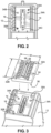
FIG. 1 is an exploded, perspective bottom view of a fluid cartridge according to the disclosure. -
FIG. 2 is a plan bottom view of a portion of the fluid cartridge showing details of a bottom wall of the fluid cartridge ofFIG. 1 . -
FIG. 3 is a partial perspective view of the fluid cartridge ofFIG. 1 and metal insert therefor. -
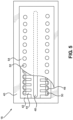
FIG. 4 is a plan view of top side of the metal insert for the fluid cartridge ofFIG. 1 according to an embodiment of the disclosure. -
FIG. 5 is a plan view, not to scale, of an ejection head chip for the fluid cartridge ofFIG. 1 . - With reference the figures,
FIG. 1 is an exploded, bottom view of afluid cartridge 10 according to an embodiment of the disclosure. Thefluid cartridge 10 includes a plastic cartridge body (also referred to as a plastic fluid body) 12 made from a polymeric thermoplastic resin such as polyethylene, polypropylene, polyamide, polystyrene, and the like. As shown inFIGs. 2-3 , abottom wall 14 of thecartridge body 12 contains a fluid supply opening 16 therein for providing fluid from thecartridge body 12 to anejection head chip 18 that is electrically attached to aflexible circuit 20. Afluid filter 22 is provided in thecartridge body 12 on a filter tower structure to filter the fluid flowing to theejection head chip 18. - According to an embodiment of the disclosure, a
metal insert 24 is attached by means of afirst adhesive 26 to thebottom wall 14 of thecartridge body 12. Asecond adhesive 28 is used to bond theflexible circuit 20 to themetal insert 24 while also insulating the metal insert from lead beams on theflexible circuit 20. Themetal insert 24 has an overall thickness ranging from about 1.5 to about 4 mm in thickness and will typically have a thickness ranging from about 1.75 to about 2.5 mm. The length L of themetal insert 24 may range from about 18 to about 25 mm and the width W of themetal insert 24 may range from about 12 to about 14 mm. A particularlysuitable metal insert 24 is a machined, molded, or stamped metal insert formed from a metal selected from aluminum and stainless steel. The aluminum may be an anodized aluminum or the metal insert may include an inert coating to prevent flocculation of solids from fluids ejected by theejection head chip 18. - The
bottom wall 14 of thecartridge body 12 also includes at least twoguide pins metal insert 24 into place on thebottom wall 14 of thecartridge body 12. As shown inFIG. 4 , themetal insert 24 includesapertures bottom wall 14 of thecartridge body 12 to enable easy placement of themetal insert 24 on thebottom wall 14 of thecartridge body 12 as shown inFIGs. 1 and3 . - Another feature of the
bottom wall 14 of thecartridge body 12 is theplanarization pads 34A-34C that provide a substantially planar surface for the attachment of themetal insert 24 to thebottom wall 14 of thecartridge body 12. Theplanarization pads 34A-34C may be raised pads molded into thebottom wall 14 of thecartridge body 12 or machined to provide a planar surface to which themetal insert 24 is adhesively attached. - The
first adhesive 26 used to attach themetal insert 24 to thebottom wall 14 of thecartridge body 12, may be a heat curable epoxy adhesive that is compatible with the resin used to make thecartridge body 12. In order to enhance adhesion between themetal insert 24 and thebottom wall 14, theunderside 36 of themetal insert 24 may be cleaned and treated with water, isopropyl alcohol, or silane. Theunderside 36 may also be blasted with a high pressure stream of air or aluminum oxide to enhance adhesion. Likewise, thebottom wall 14 of the cartridge body may be coated with an adhesion enhancing coating such as a silane coating. - Once the
metal insert 24 is adhesively attached to thebottom wall 14 of the cartridge body, theejection head chip 18 may be adhesively attached to themetal insert 24 using a die bond adhesive. A conventionalejection head chip 18 is illustrated inFIG. 5 and includes asilicon semiconductor substrate 40 that includes aflow feature layer 42 made from a photoresist material havingfluid channels 44 andfluid chambers 46 photoimaged therein. A fluid supply via 48 is etched through thesemiconductor substrate 40 and imaged in theflow feature layer 42 and provides fluid to thefluid channels 44 andfluid chambers 46. Each of thefluid chambers 46 includes afluid ejection device 50 that may be selected from a resistor heater or a piezoelectric device for ejecting fluid from thefluid chambers 46 through associatednozzle holes 52 in anozzle plate 54 attached to theflow feature layer 42. Because a fluid supply via 48 in theejection head chip 18 must be precisely aligned with a fluid supply slot 56 in themetal insert 24 in order to provide fluid tofluid ejectors 50 on theejection head chip 18, achip pocket 58 is provided in the metal insert 24 (FIG. 3 ) and theejection head chip 18 is adhesively attached to themetal insert 24 in thechip pocket 58. Thechip pocket 58 is a recessed area in themetal insert 24 that provides a somewhat confined area for the die bond adhesive. The fluid supply slot 56 in themetal insert 24 has a length ranging from about 14.8 mm to about 15.6 mm and a width ranging from about 1.5 to about 2.0 mm. - The
flexible circuit 20, which is used to connectfluid ejectors 50 on theejection head chip 18 with a control activation device for thefluid ejectors 50, surrounds theejection head chip 18 and is fastened to themetal insert 24 using thesecond adhesive 28, also known as a preform pressure sensitive adhesive. Theflexible circuit 20 includes a plurality of beams which extend therefrom and electrically connect with bond pads (not shown) on thesemiconductor substrate 40 of theejection head chip 18. After theejection head chip 18 is placed within thechip pocket 58 and theflexible circuit 20 is attached to theejection head chip 18, an ultraviolet (UV) photosensitive adhesive is applied along the sides of theejection head chip 18, over the beams, as an encapsulant and protectant to prevent shorting by themetal insert 24 and corrosion from fluid ejected by theejection head chip 18. A light source is applied to the UV adhesive to cure the same. However, a portion of the UV adhesive which flows around and behind the beams is not exposed to the applied UV light source, and therefore is not cured thereby. - Once the
fluid cartridge 10 is fully assembled, thefluid cartridge 10 is placed within an oven and the die bond adhesive is cured at an elevated temperature to permanently affix theejection head chip 18 to themetal insert 24. During the curing process, the adhesive may produce gas which forms gas bubbles in the adhesive. Some of the gas may remain entrapped within the adhesive as residual gas bubbles after the curing process is finished. Such gas bubbles, because of the void left in the adhesive, may affect the bond strength between theejection head chip 18 and themetal insert 24. Moreover, other gas bubbles may expand at the elevated cure temperature and/or join with adjacent gas bubbles to form passageways or channels within the adhesive. Such a phenomenon, known as "die bond channeling," may result in channels which extend from the fluid supply slot 56 within themetal insert 24 to the ambient environment, thereby allowing fluid to leak from the fluid cartridge assembly to the ambient environment. Alternatively, in the case of a multi-fluid cartridge assembly, the channels formed in the adhesive may allow cross-contamination between the different fluids within thecartridge body 12. - Additionally, the uncured UV or thermally cured epoxy adhesive is subsequently cured and/or volatilized by the heating process used to cure the die bond adhesive. During the heat curing process, the UV and/or thermally cured epoxy adhesive may also produce gas. Because the UV and/or thermally cured epoxy adhesive placed over the beams on each side of the
ejection head chip 18 has previously been cured, and theflexible circuit 20 is affixed to themetal insert 24 and surrounds theejection head chip 18, gas which is produced during the heat curing process may expand (because of the increased temperature) and flow through the die bond adhesive and UV adhesive toward and into the fluid supply slot 56 within themetal insert 24 creating channels for leaking of fluid from the fluid supply cartridge out to the ambient environment. - Accordingly, the
metal insert 24 is configured with at least one air vent, and preferably, a plurality of air vents adjacent to thechip pocket 58 to enable air to escape from the die bond adhesive and/or UV adhesive during the curing process. With reference again toFIG. 4 , themetal insert 24 includes a plurality ofgrooves chip pocket 58 that provide air flow communication from thechip pocket 58 to the ambient atmosphere.Grooves 60 define one or more longitudinal grooves (extending substantially parallel to a longitudinal direction ofchip pocket 58 along longitudinal axis 64), andgrooves 62 define a plurality of lateral grooves extending betweenchip pocket 58 andlongitudinal grooves 60.Longitudinal grooves 60 extend toedges longitudinal grooves lateral grooves 62 that are in flow communication with the ambient atmosphere atedges metal insert 24 provide the plurality of air vents for themetal insert 24. Exemplary air flow through thegrooves chip pocket 58 toedges arrows - The grooves have dimensions corresponding to the dimensions represented by the reference letters W1, S and L1. The dimension W1 is preferably between 0.15 and 0.75 mm, and more preferably between 0.2 and 0.3 mm. The dimension S is preferably between 0.75 and 2.5 mm, and more preferably between 1 and 2 mm. The dimension L1 is preferably between 1.0 and 4.0 mm, and more preferably between 1.5 and 2.5 mm. Further,
grooves - (substantially perpendicular to the drawing in
FIG. 4 ) which is preferably between 0.1 and 0.5 mm, and more preferably between 0.25 and 0.35 mm. A raisedracetrack 70 having a height ranging from about 0.04 to about 0.1 mm and a width ranging from about 0.15 mm to about 0.5 mm circumscribes the fluid supply slot 56 to prevent a die bond adhesive applied in thechip pocket 58 from flowing into the fluid supply slot 56. An internallongitudinal groove 72 having the width W1 is provided between thechip pocket 58 and the raised structures 74 to provide a raised landing area relative to thechip pocket 58 for the die bond and/or UV adhesive to coat the back side of the lead beams on theflexible circuit 20 and to prevent short circuiting between theflexible circuit 20 and themetal insert 24. - During the heat curing process for the die bond adhesive and/or the UV adhesive, any gas generated will flow from the
lateral grooves 62 to thelongitudinal grooves edges metal insert 24 containing thegrooves - An advantage of having the
ejection head chip 18 bonded to themetal insert 24 rather than to theplastic cartridge body 12 is that themetal insert 24 provides a mechanically stable surface for theejection head chip 18 so that any swelling or distortion of theplastic cartridge body 12 is isolated from theejection head chip 18. Accordingly, a wider variety of fluids may be ejected with afluid cartridge 10 having themetal insert 24 as described above, including organic fluids that may cause the resin of thecartridge body 12 to swell. In some embodiments, when using ametal insert 24, themetal insert 24 may also provide a heat sink for cooling theejection head chip 18 during fluid ejection. - While the foregoing embodiments are directed specifically to metal inserts, other dimensionally stable materials, such as ceramic and carbon fiber reinforced polymers may be used as an insert. Such alternative materials may also be formed with vents as described above to prevent air channels from forming in the bonding adhesives during heat curing cycles.
- It is noted that, as used in this specification and the appended claims, the singular forms "a," "an," and "the," include plural referents unless expressly and unequivocally limited to one referent. As used herein, the term "include" and its grammatical variants are intended to be non-limiting, such that recitation of items in a list is not to the exclusion of other like items that can be substituted or added to the listed items.
- For the purposes of this specification and appended claims, unless otherwise indicated, all numbers expressing quantities, percentages or proportions, and other numerical values used in the specification and claims, are to be understood as being modified in all instances by the term "about." Accordingly, unless indicated to the contrary, the numerical parameters set forth in the following specification and attached claims are approximations that can vary depending upon the desired properties sought to be obtained by the present disclosure. At the very least, and not as an attempt to limit the application of the doctrine of equivalents to the scope of the claims, each numerical parameter should at least be construed in light of the number of reported significant digits and by applying ordinary rounding techniques.
Claims (19)
- A fluid cartridge (10) comprising:a plastic fluid body (12) having a bottom wall (14) having a fluid supply opening (16) therein;a metal insert (24) adhesively attached to the bottom wall (14), the metal insert (24) having a fluid supply slot (56) therein corresponding to the fluid supply opening (16) in the bottom wall (14), a die bond surface adjacent to the fluid supply slot (56) for adhesively attaching an ejection head chip thereto, and a plurality of air vents adjacent to the die bond surface; andan ejection head chip (18) adhesively attached to the die bond surface of the metal insert (24).
- The fluid cartridge (10) of claim 1, wherein the metal insert (24) is a stamped, machined, or molded metal insert.
- The fluid cartridge (10) of claim 1, wherein the metal insert (24) comprises aluminum or stainless steel.
- The fluid cartridge (10) of claim 3, wherein the metal insert (24) comprises anodized aluminum.
- The fluid cartridge (10) of claim 1, wherein the metal insert (24) further comprises a stamped chip pocket (58) in the die bond surface for adhesively attaching the ejection head chip (18) therein.
- The fluid cartridge (10) of claim 5, wherein the chip pocket (58) further comprises a racetrack (70) circumscribing the fluid supply slot (56).
- The fluid cartridge (10) of claim 5, wherein the metal insert (24) further comprises a deck area between the chip pocket (58) and the air vents for a die bond adhesive that is effective to electrically and chemically insolate a back side of a flexible circuit (20) from the metal insert (24) and corrosive fluids.
- The fluid cartridge (10) of claim 1, wherein the metal insert (24) has a thickness ranging from about 1.5 to about 4 millimeters.
- The fluid cartridge (10) of claim 1, further comprising at least two guide pins (30A, 30B) extending orthogonally from the bottom wall (14).
- The fluid cartridge (10) of claim 9, wherein the metal insert (24) further comprises apertures (32A, 32B) therein corresponding to the at least two guide pins (30A, 30B) for positioning the metal insert (24) on the bottom wall (14) of the plastic fluid body (12).
- The fluid cartridge (10) of claim 1, further comprising a flexible circuit (20) electrically connected to the ejection head chip (18).
- A method for eliminating mechanical stresses on an ejection head chip comprising:providing a fluid cartridge (10) comprising a plastic fluid body (12) having a bottom wall (14) having a fluid supply opening (16) therein;adhesively attaching a metal insert (24) to the bottom wall (14), wherein the metal insert (24) has a fluid supply slot (56) therein corresponding to the fluid supply opening (16) in the bottom wall (14), a die bond surface adjacent to the fluid supply slot (56) for adhesively attaching an ejection head chip thereto, and a plurality of air vents adjacent to the die bond surface;adhesively attaching an ejection head chip (18) to the die bond surface of the metal insert (24); andelectrically connecting a flexible circuit (20) to the ejection head chip (18).
- The method of claim 12, wherein the metal insert (24) is a stamped metal insert (24).
- The method of claim 12, wherein the metal insert (24) comprises aluminum or stainless steel, further comprising coating the metal insert (24) with an inert coating to prevent flocculation of solids from fluids ejected by the ejection head chip (18).
- The method of claim 12, wherein the metal insert (24) comprises a stamped chip pocket (58) within the die bond surface having a racetrack (70) circumscribing the fluid supply slot (56), further comprising applying a die bond adhesive in the chip pocket (58) for adhesively attaching the ejection head chip (18) to the metal insert (24) in the chip pocket (58).
- The method of claim 15, wherein the metal insert (24) comprises a deck area between the chip pocket (58) and the air vents, further comprising applying a die bond adhesive in the deck area to electrically and chemically insolate a back side of the flexible circuit (20) from the metal insert (24) and corrosive fluids.
- The method of claim 12, further comprising stamping the metal insert (24) from aluminum or stainless steel having a thickness ranging from about 1.5 to about 4 millimeters.
- The method of claim 12, further comprising molding at least two guide pins (30A, 30B) to extend orthogonally from the bottom wall (14) of the plastic fluid body (12).
- The method of claim 18, further comprising providing apertures (32A, 32B) in the metal insert (24) corresponding to the at least two guide pins (30A, 30B), and positioning the metal insert (24) on the bottom wall (14) of the plastic fluid body (12) using the at least two guide pins (30A, 30B) and apertures (32A, 32B).
Applications Claiming Priority (1)
| Application Number | Priority Date | Filing Date | Title |
|---|---|---|---|
| US17/454,130 US11865843B2 (en) | 2021-11-09 | 2021-11-09 | Fluid cartridge with vented insert |
Publications (2)
| Publication Number | Publication Date |
|---|---|
| EP4177061A1 true EP4177061A1 (en) | 2023-05-10 |
| EP4177061B1 EP4177061B1 (en) | 2024-08-07 |
Family
ID=83996768
Family Applications (1)
| Application Number | Title | Priority Date | Filing Date |
|---|---|---|---|
| EP22203618.8A Active EP4177061B1 (en) | 2021-11-09 | 2022-10-25 | Fluid cartridge and method for eliminating mechanical stresses on ejection head chip |
Country Status (4)
| Country | Link |
|---|---|
| US (1) | US11865843B2 (en) |
| EP (1) | EP4177061B1 (en) |
| JP (1) | JP2023070652A (en) |
| CN (1) | CN116099694A (en) |
Families Citing this family (1)
| Publication number | Priority date | Publication date | Assignee | Title |
|---|---|---|---|---|
| US12583230B2 (en) | 2021-11-09 | 2026-03-24 | Brady Worldwide, Inc. | Fluid cartridge with vented insert |
Citations (4)
| Publication number | Priority date | Publication date | Assignee | Title |
|---|---|---|---|---|
| EP0646466B1 (en) * | 1993-10-05 | 2000-06-14 | Hewlett-Packard Company | Print cartridge body and nozzle member |
| US6398354B1 (en) * | 1999-06-30 | 2002-06-04 | Lexmark International, Inc. | Printhead apparatus and printer having separate filtration device and method for attaching said device |
| US20090066759A1 (en) * | 2007-09-12 | 2009-03-12 | Shirish Padmakar Mulay | Methods and apparatus for improved ejection head planarity and reduced ejection head damage |
| US20220402645A1 (en) * | 2021-06-22 | 2022-12-22 | Funai Electric Co., Ltd. | Hybrid fluid cartridge |
Family Cites Families (12)
| Publication number | Priority date | Publication date | Assignee | Title |
|---|---|---|---|---|
| US5751324A (en) | 1996-03-14 | 1998-05-12 | Lexmark International, Inc. | Ink jet cartridge body with vented die cavity |
| US6280013B1 (en) * | 1997-11-05 | 2001-08-28 | Hewlett-Packard Company | Heat exchanger for an inkjet printhead |
| US6463656B1 (en) * | 2000-06-29 | 2002-10-15 | Eastman Kodak Company | Laminate and gasket manfold for ink jet delivery systems and similar devices |
| US7658470B1 (en) * | 2005-04-28 | 2010-02-09 | Hewlett-Packard Development Company, L.P. | Method of using a flexible circuit |
| US7600850B2 (en) * | 2006-03-01 | 2009-10-13 | Lexmark International, Inc. | Internal vent channel in ejection head assemblies and methods relating thereto |
| JP2011062963A (en) | 2009-09-18 | 2011-03-31 | Canon Inc | Manufacturing method of liquid discharging head |
| JP2011212896A (en) * | 2010-03-31 | 2011-10-27 | Seiko Epson Corp | Liquid ejecting head, liquid ejecting unit, and liquid ejecting apparatus |
| JP2013022848A (en) | 2011-07-21 | 2013-02-04 | Ricoh Co Ltd | Liquid drop ejection head, method for manufacturing the same, and liquid drop ejector |
| US9365044B1 (en) * | 2014-12-12 | 2016-06-14 | Funai Electric Co., Ltd. | Printhead cartridge with hydrophobic coating |
| US9987644B1 (en) | 2016-12-07 | 2018-06-05 | Funai Electric Co., Ltd. | Pedestal chip mount for fluid delivery device |
| JP2018103376A (en) | 2016-12-22 | 2018-07-05 | セイコーエプソン株式会社 | Liquid injection head and liquid injection device |
| CN110325372B (en) * | 2017-04-05 | 2022-02-18 | 惠普发展公司,有限责任合伙企业 | Fluid ejection device, print bar, and fluid flow structure |
-
2021
- 2021-11-09 US US17/454,130 patent/US11865843B2/en active Active
-
2022
- 2022-10-25 EP EP22203618.8A patent/EP4177061B1/en active Active
- 2022-11-01 JP JP2022175181A patent/JP2023070652A/en active Pending
- 2022-11-03 CN CN202211369409.1A patent/CN116099694A/en active Pending
Patent Citations (4)
| Publication number | Priority date | Publication date | Assignee | Title |
|---|---|---|---|---|
| EP0646466B1 (en) * | 1993-10-05 | 2000-06-14 | Hewlett-Packard Company | Print cartridge body and nozzle member |
| US6398354B1 (en) * | 1999-06-30 | 2002-06-04 | Lexmark International, Inc. | Printhead apparatus and printer having separate filtration device and method for attaching said device |
| US20090066759A1 (en) * | 2007-09-12 | 2009-03-12 | Shirish Padmakar Mulay | Methods and apparatus for improved ejection head planarity and reduced ejection head damage |
| US20220402645A1 (en) * | 2021-06-22 | 2022-12-22 | Funai Electric Co., Ltd. | Hybrid fluid cartridge |
Also Published As
| Publication number | Publication date |
|---|---|
| EP4177061B1 (en) | 2024-08-07 |
| US20230143469A1 (en) | 2023-05-11 |
| US11865843B2 (en) | 2024-01-09 |
| CN116099694A (en) | 2023-05-12 |
| JP2023070652A (en) | 2023-05-19 |
Similar Documents
| Publication | Publication Date | Title |
|---|---|---|
| US7591546B2 (en) | Tank unit, ink jet recording head and method of manufacturing tank unit and ink jet recording head | |
| US7712870B2 (en) | Ink jet recording head with sealant filling region in substrate | |
| US20080202694A1 (en) | Fluid flow path in microfluidic device | |
| US11865843B2 (en) | Fluid cartridge with vented insert | |
| US9827764B2 (en) | Liquid ejecting head and liquid ejecting apparatus with improved mechanical strength | |
| US12583230B2 (en) | Fluid cartridge with vented insert | |
| JP6222985B2 (en) | Liquid discharge head, element substrate, and method of manufacturing liquid discharge head | |
| JP6548419B2 (en) | Liquid discharge head and method of manufacturing liquid discharge head | |
| US20200198345A1 (en) | Liquid ejection head and manufacturing method thereof | |
| EP4108463A1 (en) | Fluid cartridge and method for eliminating mechanical stresses on ejection head chip | |
| JP2009101645A (en) | Recording head and manufacturing method thereof | |
| US7043838B2 (en) | Process for manufacturing a micro-fluid ejection device | |
| US7275815B2 (en) | Die attach methods and apparatus for micro-fluid ejection device | |
| US8161648B2 (en) | Method of manufacturing recording head | |
| JP5053927B2 (en) | Inkjet recording head unit and method for manufacturing the same | |
| US7311386B2 (en) | Die attach methods and apparatus for micro-fluid ejection device | |
| US12459262B2 (en) | Liquid ejection head and method of manufacturing the same | |
| JP2000141667A (en) | Method of manufacturing inkjet head | |
| JP7642339B2 (en) | Discharge device, method for manufacturing discharge device, and imprint device | |
| JP2025109460A (en) | Liquid ejection head | |
| JP2025034428A (en) | LIQUID EJECTION HEAD AND LIQUID EJECTION APPARATUS | |
| JP2024094665A (en) | LIQUID DISCHARGE HEAD AND METHOD FOR MANUFACTURING LIQUID DISCHARGE HEAD | |
| US20200023368A1 (en) | Method for integrating structures in a support and associated device | |
| JPH0490310A (en) | Method and mold for forming molded member on substrate | |
| JPH03184866A (en) | Inkjet recording head assembly equipment |
Legal Events
| Date | Code | Title | Description |
|---|---|---|---|
| PUAI | Public reference made under article 153(3) epc to a published international application that has entered the european phase |
Free format text: ORIGINAL CODE: 0009012 |
|
| STAA | Information on the status of an ep patent application or granted ep patent |
Free format text: STATUS: THE APPLICATION HAS BEEN PUBLISHED |
|
| AK | Designated contracting states |
Kind code of ref document: A1 Designated state(s): AL AT BE BG CH CY CZ DE DK EE ES FI FR GB GR HR HU IE IS IT LI LT LU LV MC ME MK MT NL NO PL PT RO RS SE SI SK SM TR |
|
| STAA | Information on the status of an ep patent application or granted ep patent |
Free format text: STATUS: REQUEST FOR EXAMINATION WAS MADE |
|
| 17P | Request for examination filed |
Effective date: 20230620 |
|
| RBV | Designated contracting states (corrected) |
Designated state(s): AL AT BE BG CH CY CZ DE DK EE ES FI FR GB GR HR HU IE IS IT LI LT LU LV MC ME MK MT NL NO PL PT RO RS SE SI SK SM TR |
|
| GRAP | Despatch of communication of intention to grant a patent |
Free format text: ORIGINAL CODE: EPIDOSNIGR1 |
|
| STAA | Information on the status of an ep patent application or granted ep patent |
Free format text: STATUS: GRANT OF PATENT IS INTENDED |
|
| RIC1 | Information provided on ipc code assigned before grant |
Ipc: B41J 2/175 20060101ALI20240429BHEP Ipc: B41J 2/16 20060101ALI20240429BHEP Ipc: B41J 2/14 20060101AFI20240429BHEP |
|
| INTG | Intention to grant announced |
Effective date: 20240528 |
|
| GRAS | Grant fee paid |
Free format text: ORIGINAL CODE: EPIDOSNIGR3 |
|
| GRAA | (expected) grant |
Free format text: ORIGINAL CODE: 0009210 |
|
| STAA | Information on the status of an ep patent application or granted ep patent |
Free format text: STATUS: THE PATENT HAS BEEN GRANTED |
|
| AK | Designated contracting states |
Kind code of ref document: B1 Designated state(s): AL AT BE BG CH CY CZ DE DK EE ES FI FR GB GR HR HU IE IS IT LI LT LU LV MC ME MK MT NL NO PL PT RO RS SE SI SK SM TR |
|
| REG | Reference to a national code |
Ref country code: GB Ref legal event code: FG4D |
|
| REG | Reference to a national code |
Ref country code: CH Ref legal event code: EP |
|
| REG | Reference to a national code |
Ref country code: IE Ref legal event code: FG4D |
|
| REG | Reference to a national code |
Ref country code: DE Ref legal event code: R096 Ref document number: 602022005149 Country of ref document: DE |
|
| REG | Reference to a national code |
Ref country code: LT Ref legal event code: MG9D |
|
| REG | Reference to a national code |
Ref country code: NL Ref legal event code: MP Effective date: 20240807 |
|
| PG25 | Lapsed in a contracting state [announced via postgrant information from national office to epo] |
Ref country code: NO Free format text: LAPSE BECAUSE OF FAILURE TO SUBMIT A TRANSLATION OF THE DESCRIPTION OR TO PAY THE FEE WITHIN THE PRESCRIBED TIME-LIMIT Effective date: 20241107 |
|
| REG | Reference to a national code |
Ref country code: AT Ref legal event code: MK05 Ref document number: 1710524 Country of ref document: AT Kind code of ref document: T Effective date: 20240807 |
|
| PG25 | Lapsed in a contracting state [announced via postgrant information from national office to epo] |
Ref country code: FI Free format text: LAPSE BECAUSE OF FAILURE TO SUBMIT A TRANSLATION OF THE DESCRIPTION OR TO PAY THE FEE WITHIN THE PRESCRIBED TIME-LIMIT Effective date: 20240807 Ref country code: NL Free format text: LAPSE BECAUSE OF FAILURE TO SUBMIT A TRANSLATION OF THE DESCRIPTION OR TO PAY THE FEE WITHIN THE PRESCRIBED TIME-LIMIT Effective date: 20240807 Ref country code: PL Free format text: LAPSE BECAUSE OF FAILURE TO SUBMIT A TRANSLATION OF THE DESCRIPTION OR TO PAY THE FEE WITHIN THE PRESCRIBED TIME-LIMIT Effective date: 20240807 Ref country code: GR Free format text: LAPSE BECAUSE OF FAILURE TO SUBMIT A TRANSLATION OF THE DESCRIPTION OR TO PAY THE FEE WITHIN THE PRESCRIBED TIME-LIMIT Effective date: 20241108 Ref country code: PT Free format text: LAPSE BECAUSE OF FAILURE TO SUBMIT A TRANSLATION OF THE DESCRIPTION OR TO PAY THE FEE WITHIN THE PRESCRIBED TIME-LIMIT Effective date: 20241209 |
|
| PG25 | Lapsed in a contracting state [announced via postgrant information from national office to epo] |
Ref country code: BG Free format text: LAPSE BECAUSE OF FAILURE TO SUBMIT A TRANSLATION OF THE DESCRIPTION OR TO PAY THE FEE WITHIN THE PRESCRIBED TIME-LIMIT Effective date: 20240807 |
|
| PG25 | Lapsed in a contracting state [announced via postgrant information from national office to epo] |
Ref country code: LV Free format text: LAPSE BECAUSE OF FAILURE TO SUBMIT A TRANSLATION OF THE DESCRIPTION OR TO PAY THE FEE WITHIN THE PRESCRIBED TIME-LIMIT Effective date: 20240807 |
|
| PG25 | Lapsed in a contracting state [announced via postgrant information from national office to epo] |
Ref country code: AT Free format text: LAPSE BECAUSE OF FAILURE TO SUBMIT A TRANSLATION OF THE DESCRIPTION OR TO PAY THE FEE WITHIN THE PRESCRIBED TIME-LIMIT Effective date: 20240807 Ref country code: IS Free format text: LAPSE BECAUSE OF FAILURE TO SUBMIT A TRANSLATION OF THE DESCRIPTION OR TO PAY THE FEE WITHIN THE PRESCRIBED TIME-LIMIT Effective date: 20241207 |
|
| PG25 | Lapsed in a contracting state [announced via postgrant information from national office to epo] |
Ref country code: HR Free format text: LAPSE BECAUSE OF FAILURE TO SUBMIT A TRANSLATION OF THE DESCRIPTION OR TO PAY THE FEE WITHIN THE PRESCRIBED TIME-LIMIT Effective date: 20240807 |
|
| PG25 | Lapsed in a contracting state [announced via postgrant information from national office to epo] |
Ref country code: RS Free format text: LAPSE BECAUSE OF FAILURE TO SUBMIT A TRANSLATION OF THE DESCRIPTION OR TO PAY THE FEE WITHIN THE PRESCRIBED TIME-LIMIT Effective date: 20241107 Ref country code: ES Free format text: LAPSE BECAUSE OF FAILURE TO SUBMIT A TRANSLATION OF THE DESCRIPTION OR TO PAY THE FEE WITHIN THE PRESCRIBED TIME-LIMIT Effective date: 20240807 |
|
| PG25 | Lapsed in a contracting state [announced via postgrant information from national office to epo] |
Ref country code: RS Free format text: LAPSE BECAUSE OF FAILURE TO SUBMIT A TRANSLATION OF THE DESCRIPTION OR TO PAY THE FEE WITHIN THE PRESCRIBED TIME-LIMIT Effective date: 20241107 Ref country code: PT Free format text: LAPSE BECAUSE OF FAILURE TO SUBMIT A TRANSLATION OF THE DESCRIPTION OR TO PAY THE FEE WITHIN THE PRESCRIBED TIME-LIMIT Effective date: 20241209 Ref country code: PL Free format text: LAPSE BECAUSE OF FAILURE TO SUBMIT A TRANSLATION OF THE DESCRIPTION OR TO PAY THE FEE WITHIN THE PRESCRIBED TIME-LIMIT Effective date: 20240807 Ref country code: NO Free format text: LAPSE BECAUSE OF FAILURE TO SUBMIT A TRANSLATION OF THE DESCRIPTION OR TO PAY THE FEE WITHIN THE PRESCRIBED TIME-LIMIT Effective date: 20241107 Ref country code: NL Free format text: LAPSE BECAUSE OF FAILURE TO SUBMIT A TRANSLATION OF THE DESCRIPTION OR TO PAY THE FEE WITHIN THE PRESCRIBED TIME-LIMIT Effective date: 20240807 Ref country code: LV Free format text: LAPSE BECAUSE OF FAILURE TO SUBMIT A TRANSLATION OF THE DESCRIPTION OR TO PAY THE FEE WITHIN THE PRESCRIBED TIME-LIMIT Effective date: 20240807 Ref country code: IS Free format text: LAPSE BECAUSE OF FAILURE TO SUBMIT A TRANSLATION OF THE DESCRIPTION OR TO PAY THE FEE WITHIN THE PRESCRIBED TIME-LIMIT Effective date: 20241207 Ref country code: HR Free format text: LAPSE BECAUSE OF FAILURE TO SUBMIT A TRANSLATION OF THE DESCRIPTION OR TO PAY THE FEE WITHIN THE PRESCRIBED TIME-LIMIT Effective date: 20240807 Ref country code: GR Free format text: LAPSE BECAUSE OF FAILURE TO SUBMIT A TRANSLATION OF THE DESCRIPTION OR TO PAY THE FEE WITHIN THE PRESCRIBED TIME-LIMIT Effective date: 20241108 Ref country code: FI Free format text: LAPSE BECAUSE OF FAILURE TO SUBMIT A TRANSLATION OF THE DESCRIPTION OR TO PAY THE FEE WITHIN THE PRESCRIBED TIME-LIMIT Effective date: 20240807 Ref country code: ES Free format text: LAPSE BECAUSE OF FAILURE TO SUBMIT A TRANSLATION OF THE DESCRIPTION OR TO PAY THE FEE WITHIN THE PRESCRIBED TIME-LIMIT Effective date: 20240807 Ref country code: BG Free format text: LAPSE BECAUSE OF FAILURE TO SUBMIT A TRANSLATION OF THE DESCRIPTION OR TO PAY THE FEE WITHIN THE PRESCRIBED TIME-LIMIT Effective date: 20240807 Ref country code: AT Free format text: LAPSE BECAUSE OF FAILURE TO SUBMIT A TRANSLATION OF THE DESCRIPTION OR TO PAY THE FEE WITHIN THE PRESCRIBED TIME-LIMIT Effective date: 20240807 |
|
| PG25 | Lapsed in a contracting state [announced via postgrant information from national office to epo] |
Ref country code: DK Free format text: LAPSE BECAUSE OF FAILURE TO SUBMIT A TRANSLATION OF THE DESCRIPTION OR TO PAY THE FEE WITHIN THE PRESCRIBED TIME-LIMIT Effective date: 20240807 Ref country code: SM Free format text: LAPSE BECAUSE OF FAILURE TO SUBMIT A TRANSLATION OF THE DESCRIPTION OR TO PAY THE FEE WITHIN THE PRESCRIBED TIME-LIMIT Effective date: 20240807 |
|
| PG25 | Lapsed in a contracting state [announced via postgrant information from national office to epo] |
Ref country code: EE Free format text: LAPSE BECAUSE OF FAILURE TO SUBMIT A TRANSLATION OF THE DESCRIPTION OR TO PAY THE FEE WITHIN THE PRESCRIBED TIME-LIMIT Effective date: 20240807 |
|
| PG25 | Lapsed in a contracting state [announced via postgrant information from national office to epo] |
Ref country code: CZ Free format text: LAPSE BECAUSE OF FAILURE TO SUBMIT A TRANSLATION OF THE DESCRIPTION OR TO PAY THE FEE WITHIN THE PRESCRIBED TIME-LIMIT Effective date: 20240807 |
|
| PG25 | Lapsed in a contracting state [announced via postgrant information from national office to epo] |
Ref country code: SK Free format text: LAPSE BECAUSE OF FAILURE TO SUBMIT A TRANSLATION OF THE DESCRIPTION OR TO PAY THE FEE WITHIN THE PRESCRIBED TIME-LIMIT Effective date: 20240807 |
|
| REG | Reference to a national code |
Ref country code: DE Ref legal event code: R097 Ref document number: 602022005149 Country of ref document: DE |
|
| PLBE | No opposition filed within time limit |
Free format text: ORIGINAL CODE: 0009261 |
|
| STAA | Information on the status of an ep patent application or granted ep patent |
Free format text: STATUS: NO OPPOSITION FILED WITHIN TIME LIMIT |
|
| REG | Reference to a national code |
Ref country code: GB Ref legal event code: 732E Free format text: REGISTERED BETWEEN 20250529 AND 20250604 |
|
| 26N | No opposition filed |
Effective date: 20250508 |
|
| REG | Reference to a national code |
Ref country code: DE Ref legal event code: R081 Ref document number: 602022005149 Country of ref document: DE Owner name: BRADY WORLDWIDE, INC., MILWAUKEE, US Free format text: FORMER OWNER: FUNAI ELECTRIC CO., LTD., DAITO, OSAKA, JP Ref country code: DE Ref legal event code: R082 Ref document number: 602022005149 Country of ref document: DE Representative=s name: BOULT WADE TENNANT LLP, DE |
|
| PG25 | Lapsed in a contracting state [announced via postgrant information from national office to epo] |
Ref country code: SE Free format text: LAPSE BECAUSE OF FAILURE TO SUBMIT A TRANSLATION OF THE DESCRIPTION OR TO PAY THE FEE WITHIN THE PRESCRIBED TIME-LIMIT Effective date: 20240807 |
|
| PGFP | Annual fee paid to national office [announced via postgrant information from national office to epo] |
Ref country code: MC Payment date: 20250923 Year of fee payment: 4 |
|
| PG25 | Lapsed in a contracting state [announced via postgrant information from national office to epo] |
Ref country code: IE Free format text: LAPSE BECAUSE OF NON-PAYMENT OF DUE FEES Effective date: 20241025 |
|
| REG | Reference to a national code |
Ref country code: CH Ref legal event code: U11 Free format text: ST27 STATUS EVENT CODE: U-0-0-U10-U11 (AS PROVIDED BY THE NATIONAL OFFICE) Effective date: 20251101 |
|
| PGFP | Annual fee paid to national office [announced via postgrant information from national office to epo] |
Ref country code: LU Payment date: 20251024 Year of fee payment: 4 |
|
| PG25 | Lapsed in a contracting state [announced via postgrant information from national office to epo] |
Ref country code: RO Free format text: LAPSE BECAUSE OF FAILURE TO SUBMIT A TRANSLATION OF THE DESCRIPTION OR TO PAY THE FEE WITHIN THE PRESCRIBED TIME-LIMIT Effective date: 20240807 |
|
| PGFP | Annual fee paid to national office [announced via postgrant information from national office to epo] |
Ref country code: DE Payment date: 20251028 Year of fee payment: 4 |
|
| PGFP | Annual fee paid to national office [announced via postgrant information from national office to epo] |
Ref country code: FR Payment date: 20251027 Year of fee payment: 4 |
|
| PGFP | Annual fee paid to national office [announced via postgrant information from national office to epo] |
Ref country code: BE Payment date: 20251024 Year of fee payment: 4 |
|
| PGFP | Annual fee paid to national office [announced via postgrant information from national office to epo] |
Ref country code: CH Payment date: 20251101 Year of fee payment: 4 |
|
| PG25 | Lapsed in a contracting state [announced via postgrant information from national office to epo] |
Ref country code: IT Free format text: LAPSE BECAUSE OF FAILURE TO SUBMIT A TRANSLATION OF THE DESCRIPTION OR TO PAY THE FEE WITHIN THE PRESCRIBED TIME-LIMIT Effective date: 20240807 Ref country code: CY Free format text: LAPSE BECAUSE OF FAILURE TO SUBMIT A TRANSLATION OF THE DESCRIPTION OR TO PAY THE FEE WITHIN THE PRESCRIBED TIME-LIMIT; INVALID AB INITIO Effective date: 20221025 |
|
| PG25 | Lapsed in a contracting state [announced via postgrant information from national office to epo] |
Ref country code: HU Free format text: LAPSE BECAUSE OF FAILURE TO SUBMIT A TRANSLATION OF THE DESCRIPTION OR TO PAY THE FEE WITHIN THE PRESCRIBED TIME-LIMIT; INVALID AB INITIO Effective date: 20221025 |
|
| PG25 | Lapsed in a contracting state [announced via postgrant information from national office to epo] |
Ref country code: TR Free format text: LAPSE BECAUSE OF FAILURE TO SUBMIT A TRANSLATION OF THE DESCRIPTION OR TO PAY THE FEE WITHIN THE PRESCRIBED TIME-LIMIT Effective date: 20240807 |
|
| PG25 | Lapsed in a contracting state [announced via postgrant information from national office to epo] |
Ref country code: SI Free format text: LAPSE BECAUSE OF FAILURE TO SUBMIT A TRANSLATION OF THE DESCRIPTION OR TO PAY THE FEE WITHIN THE PRESCRIBED TIME-LIMIT Effective date: 20240807 |
|
| PG25 | Lapsed in a contracting state [announced via postgrant information from national office to epo] |
Ref country code: ME Free format text: LAPSE BECAUSE OF FAILURE TO SUBMIT A TRANSLATION OF THE DESCRIPTION OR TO PAY THE FEE WITHIN THE PRESCRIBED TIME-LIMIT Effective date: 20240807 |
|
| PG25 | Lapsed in a contracting state [announced via postgrant information from national office to epo] |
Ref country code: LT Free format text: LAPSE BECAUSE OF FAILURE TO SUBMIT A TRANSLATION OF THE DESCRIPTION OR TO PAY THE FEE WITHIN THE PRESCRIBED TIME-LIMIT Effective date: 20240807 |