EP4177005A2 - Improved working unit - Google Patents
Improved working unit Download PDFInfo
- Publication number
- EP4177005A2 EP4177005A2 EP22204625.2A EP22204625A EP4177005A2 EP 4177005 A2 EP4177005 A2 EP 4177005A2 EP 22204625 A EP22204625 A EP 22204625A EP 4177005 A2 EP4177005 A2 EP 4177005A2
- Authority
- EP
- European Patent Office
- Prior art keywords
- working
- piston
- tool
- force
- detecting device
- Prior art date
- Legal status (The legal status is an assumption and is not a legal conclusion. Google has not performed a legal analysis and makes no representation as to the accuracy of the status listed.)
- Pending
Links
Images



Classifications
-
- B—PERFORMING OPERATIONS; TRANSPORTING
- B23—MACHINE TOOLS; METAL-WORKING NOT OTHERWISE PROVIDED FOR
- B23Q—DETAILS, COMPONENTS, OR ACCESSORIES FOR MACHINE TOOLS, e.g. ARRANGEMENTS FOR COPYING OR CONTROLLING; MACHINE TOOLS IN GENERAL CHARACTERISED BY THE CONSTRUCTION OF PARTICULAR DETAILS OR COMPONENTS; COMBINATIONS OR ASSOCIATIONS OF METAL-WORKING MACHINES, NOT DIRECTED TO A PARTICULAR RESULT
- B23Q5/00—Driving or feeding mechanisms; Control arrangements therefor
- B23Q5/22—Feeding members carrying tools or work
- B23Q5/26—Fluid-pressure drives
- B23Q5/261—Fluid-pressure drives for spindles
-
- B—PERFORMING OPERATIONS; TRANSPORTING
- B23—MACHINE TOOLS; METAL-WORKING NOT OTHERWISE PROVIDED FOR
- B23B—TURNING; BORING
- B23B39/00—General-purpose boring or drilling machines or devices; Sets of boring and/or drilling machines
- B23B39/16—Drilling machines with a plurality of working-spindles; Drilling automatons
-
- B—PERFORMING OPERATIONS; TRANSPORTING
- B23—MACHINE TOOLS; METAL-WORKING NOT OTHERWISE PROVIDED FOR
- B23B—TURNING; BORING
- B23B49/00—Measuring or gauging equipment on boring machines for positioning or guiding the drill; Devices for indicating failure of drills during boring; Centering devices for holes to be bored
- B23B49/001—Devices for detecting or indicating failure of drills
-
- B—PERFORMING OPERATIONS; TRANSPORTING
- B23—MACHINE TOOLS; METAL-WORKING NOT OTHERWISE PROVIDED FOR
- B23Q—DETAILS, COMPONENTS, OR ACCESSORIES FOR MACHINE TOOLS, e.g. ARRANGEMENTS FOR COPYING OR CONTROLLING; MACHINE TOOLS IN GENERAL CHARACTERISED BY THE CONSTRUCTION OF PARTICULAR DETAILS OR COMPONENTS; COMBINATIONS OR ASSOCIATIONS OF METAL-WORKING MACHINES, NOT DIRECTED TO A PARTICULAR RESULT
- B23Q17/00—Arrangements for observing, indicating or measuring on machine tools
- B23Q17/09—Arrangements for observing, indicating or measuring on machine tools for indicating or measuring cutting pressure or for determining cutting-tool condition, e.g. cutting ability, load on tool
- B23Q17/0952—Arrangements for observing, indicating or measuring on machine tools for indicating or measuring cutting pressure or for determining cutting-tool condition, e.g. cutting ability, load on tool during machining
- B23Q17/0966—Arrangements for observing, indicating or measuring on machine tools for indicating or measuring cutting pressure or for determining cutting-tool condition, e.g. cutting ability, load on tool during machining by measuring a force on parts of the machine other than a motor
-
- B—PERFORMING OPERATIONS; TRANSPORTING
- B27—WORKING OR PRESERVING WOOD OR SIMILAR MATERIAL; NAILING OR STAPLING MACHINES IN GENERAL
- B27C—PLANING, DRILLING, MILLING, TURNING OR UNIVERSAL MACHINES FOR WOOD OR SIMILAR MATERIAL
- B27C3/00—Drilling machines or drilling devices; Equipment therefor
- B27C3/04—Stationary drilling machines with a plurality of working spindles
-
- B—PERFORMING OPERATIONS; TRANSPORTING
- B27—WORKING OR PRESERVING WOOD OR SIMILAR MATERIAL; NAILING OR STAPLING MACHINES IN GENERAL
- B27C—PLANING, DRILLING, MILLING, TURNING OR UNIVERSAL MACHINES FOR WOOD OR SIMILAR MATERIAL
- B27C9/00—Multi-purpose machines; Universal machines; Equipment therefor
- B27C9/04—Multi-purpose machines; Universal machines; Equipment therefor with a plurality of working spindles
-
- B—PERFORMING OPERATIONS; TRANSPORTING
- B23—MACHINE TOOLS; METAL-WORKING NOT OTHERWISE PROVIDED FOR
- B23B—TURNING; BORING
- B23B2260/00—Details of constructional elements
- B23B2260/108—Piezoelectric elements
-
- B—PERFORMING OPERATIONS; TRANSPORTING
- B23—MACHINE TOOLS; METAL-WORKING NOT OTHERWISE PROVIDED FOR
- B23B—TURNING; BORING
- B23B2270/00—Details of turning, boring or drilling machines, processes or tools not otherwise provided for
- B23B2270/02—Use of a particular power source
- B23B2270/027—Pneumatics
Definitions
- the present invention relates to an improved working unit, in particular a unit for drilling panels and the like.
- the invention relates to an improved working unit, designed and manufactured in particular for machining pieces made of wood or other materials, such as fiberglass, plastic, metal, or the like, which can be used for any machining process which requires the use of a tool that can wear out with use.
- a drilling unit comprises a plurality of working units, equipped with a drilling bit.
- Said drilling bit is associated, in particular by means of a spindle, with a piston, arranged in a pneumatic cylinder, comprising a shell, a base, and an end stroke element.
- Said piston is movably arranged between a retracted position, in which it abuts with said base, and an extracted position, in which it abuts with said limit switch element.
- the movement of the piston from said retracted position to said extracted position occurs through the injection of air into the pneumatic cylinder. Also arranged between the piston and the shell of the pneumatic cylinder is a return spring, which tends to return said piston from said extracted position to said retracted position.
- the drilling unit is moved, by motor means, in the direction of the workpiece to be machined, from a non-operating position, in which the tool is not in contact with the workpiece to be machined, to a working position, in which the tool interferes with the workpiece.
- said piston Before performing the drilling operation, said piston is moved from said retracted position to said extracted position and, subsequently, said drilling group is moved from said non-operating position to said working position.
- the actual drilling operation takes place, during which said drilling group is moved in the direction of the piece to be machined, in such a way that said drilling bit, associated with said spindle, is placed in rotation by a motor, it penetrates inside the piece, making the hole.
- drilling bits tend to wear out with use.
- the wear of the bits or of the tool in general
- the section the surface in contact with the panel
- Therefore, a bit with a larger section tends to wear more easily than one with a smaller section.
- the same replacement criterion tends to apply, regardless of the section, with the result that some bits could be replaced when too worn, therefore, they could have worked in non-standard conditions, while others could be replaced ahead of time.
- drilling bits like all machining tools, are subject to breakage. Since a bit breakage detection system is not available, it is possible to have defective pieces, increasing production waste, with the consequent operating costs.
- object of the present invention to propose a system that can automatically detect when a specific tool, such as a specific drilling bit, a circular saw, a milling cutter, and the like has to be replaced.
- a further object of the present invention is to provide a system, that can automatically detect the breaking of a specific tool.
- Another object of the present invention is to provide a system that can detect the extracted or retracted position of a piston associated with a specific tool.
- working unit for carrying out a working, such as drilling, milling, cutting or the like, on a piece made of wood, plastic, fiberglass or the like, comprising a working tool, characterized in that it comprises a detecting device for detecting at least one input of the force exerted by said tool on said piece for carrying out said working.
- said working unit may comprise: a pneumatic cylinder; and a piston associated to said working tool; wherein said piston is movable inside said pneumatic cylinder, between a retracted position, in which said working tool is excluded, and an extracted position, in which said working tool is selected; and said detecting tool may be arranged so that when said piston is in said extracted position, said detecting device interferes with said piston for detecting said at least one input of force exerted by said tool on said piece during said working.
- said working unit may comprise an end stroke element arranged inside said pneumatic cylinder, and when said piston is in said extracted position, said end stroke element, said detecting device and said piston are arranged adjacent to each other, so that said detecting device may detect the force of said piston on said end stroke element.
- said piston when said piston is in said extracted position, it may be in abutment with said detecting device, interposed between said end stroke element and said piston.
- said detecting device may be arranged on said end stroke element.
- said detecting device may be coupled to said piston.
- said detecting device may be a piezoelectric sensor.
- said detecting device may be a load cell.
- said tool may be a drilling bit.
- said working unit may comprise returning means, such as a returning spring, for returning said piston from said extracted position to said retracted position.
- said detecting device may generate an electrical signal whose value is a substantially proportional function of the force acting when said tool carries out said working on said piece, and said detecting device may be connected to at least one control unit, configured for detecting said electric signal from said detecting signal.
- said at least one control unit may be configured for detecting if said piston exerts a mechanical stress on said limit switch element.
- It is further object of the present invention drilling group comprising: a supporting frame having one or more seats; one or more working unit, according to any one of the preceding claims, arranged as a matrix, each one housed in a respective seat of said frame; and an electric motor, associated to said supporting frame, arranged to provide the motive force necessary for moving said working units.
- said working units may be powered by compressed air for moving each piston of each working unit from said retracted position to said extracted position.
- a drilling group 1 can be seen, on which a plurality of working units 2 are installed for drilling a panel P or a piece in general, using a tool, such as a bit 21.
- the drilling group 1 comprising a support frame 11, having a plurality of seats 12, each one of which houses a working unit 2.
- the drilling group 1 also comprises an electric motor 13, to provide, by means of suitable transmission (not shown in the figure) installed within said support frame 11, the driving force required to move said working units 2.
- the drilling group 1 is also moved by possible further motor means in the direction of the piece to be working, to bring the tool, e.g., the tip 21, into contact therewith.
- the drilling group 1 can pass from a non-operative position, in which the bit 21 (or the tool, in general) is not in contact with the piece, to a working position, in which the bit is in contact with the piece.
- Each of said working units 2 is equipped with a specific bit 21 possibly of a different section according to the hole to be made.
- the bit 21 of the selected working unit 2 is placed in contact with a piece P to make one or more holes on one or more faces thereof.
- Each working unit 2 comprises a pneumatic cylinder 22 vertically arranged, coupled to said support frame 11 of the drilling group 1.
- Said pneumatic cylinder 22 is delimited by a base 221 and a shell 222.
- Compressed air is injected into the pneumatic cylinder 22 through a compressed air inlet 28.
- the compressed air inlet 28 is obtained on said base 221.
- the compressed air inlet 28 can be placed in other alternative positions.
- said compressed air inlet 28 can be obtained on said shell 222.
- cylinder pneumatic 22 also comprises a limit switch or abutment element 25, arranged inside it.
- said end stroke element 25 is arranged on the inner surface of said shell 222, at an intermediate point of the length of the pneumatic cylinder 22. The function of said end stroke element 25 will be better described below.
- each working unit 2 also comprises a piston 24, which is slidably movable inside said pneumatic cylinder 22, between a retracted position, in which it preferably abuts said base 221 of said pneumatic cylinder 22, and an extracted position, wherein said piston 24 exerts a mechanical stress on said end stroke element 25.
- Each working unit 2 also comprises a spindle 29, associated with said piston 24.
- the bit 21 of the working unit 2 is fixed to one end of said spindle 29.
- the spindle 29 is, in use, driven in rotation by said electric motor 13.
- Said end stroke element 25 is arranged so that the piston 24 can in particular be movable from said retracted position, in which it preferably abuts said base 221 of said pneumatic cylinder 22, to said extracted position, in which said piston 24 exerts a mechanical stress on said end stroke element 25.
- Said piston 24 is moved by injecting compressed air into the pneumatic cylinder 22 through said compressed air inlet 28.
- the working unit 2 also comprises return means, and in particular in the present embodiment, a returning spring 26, which is arranged inside of the pneumatic 22, between said piston 24 and said shell 222.
- the returning spring 26 is configured to return said piston 24 from said extracted position to said retracted position.
- said working unit 2 comprises a detecting device 23, arranged on said end stroke element 25, so that, when said piston 24 is in said extracted position, it exerts stress on said end stroke element 25, and said detecting device 23 is interposed between said end stroke element 25 and said piston 24.
- Said detecting device 23 is made of piezoelectric material, and it is able to detect the force that said piston 24 exerts on said end stroke element 25.
- said detecting device 23 is arranged in an internal section of said end stroke element 25.
- said piezoelectric detecting device 23 generates an electric signal following the mechanical stress received by the piston 24 on said end stroke element 25.
- the force that the piston 24 exerts on the pneumatic cylinder 22 is detected, which, as will be better described below, is proportional to that the bit 21 exerts on the piece P to be drilled.
- said detecting device 23 can be a load cell or another type of force sensor.
- Each drilling group 1 comprises one or a plurality of control units 27, connected to a respective detecting device 23.
- the control unit 27 detects the electrical signal generated by said detecting device 23, to determine, as better explained below when the force between said piston 24 and said end stroke element 25 is outside a predefinable range of values and/or if said piston 24 exerts mechanical stress on said end stroke element 25.
- the working unit 2 described above operates as follows.
- the working unit 2 Before actually drilling a piece P, the working unit 2 is selected which installs the bit 21 of interest, and compressed air is introduced through the compressed air inlet 28 of the selected working unit 2. This causes the passage of the piston 24 of the working unit 2 chosen from said retracted position, to said extracted position, in which, as mentioned, the piston 24 exerts mechanical stress on said end stroke element 25. At the same time, the returning spring 26 exerts a return force, having a direction opposite to the force exerted by the compressed air on the piston 24.
- the spindle 29 is actuated and rotated. With it, the bit 21 is rotated, to drill the piece P.
- the drilling group 1 is moved in the direction of the piece P, according to arrow A of figure 1 , i.e., in the working position, so that said bit 21 comes into contact and penetrates inside the piece to be machined, making the hole.
- the resulting force R is included in a predefined interval between a respective lower threshold value, and a respective upper threshold value.
- Bits 21 of different diameters wear out at different times.
- the resulting force R becomes less than a predetermined lower threshold value, as the resistance force to drilling P m increases.
- the electric signal generated by the detecting device 23 is processed by the control logic unit 27 in order to emit an alarm or warning signal so that the worn bit 21 can be replaced.
- the detecting device 23 When this threshold value is exceeded, the detecting device 23 emits an electric signal, processed by the control logic unit 27 in order to emit an alarm or warning signal.
- control logic unit 27 When the piston 24 exerts mechanical stress with the end stroke element 25, the control logic unit 27, by processing the electric signal emitted by the detecting device 23, is also capable of detecting the presence of the piston 24, in order to provide evidence of the extracted position of the piston 24.
- An advantage of the present invention is that of allowing the replacement of specific machining tools, in particular drilling bits, as soon as they are subject to a degree of wear, such as to cause non-optimal machining and avoid a late or early replacement.
- Another advantage of the present invention is that of reducing the machining waste by detecting the breakage of specific tools.
- Yet another advantage of the invention is that of signaling incorrect positioning of the working tools.
Landscapes
- Engineering & Computer Science (AREA)
- Mechanical Engineering (AREA)
- Life Sciences & Earth Sciences (AREA)
- Wood Science & Technology (AREA)
- Forests & Forestry (AREA)
- Machine Tool Sensing Apparatuses (AREA)
- Apparatus For Radiation Diagnosis (AREA)
- Polarising Elements (AREA)
- Sink And Installation For Waste Water (AREA)
Abstract
Description
- The present invention relates to an improved working unit, in particular a unit for drilling panels and the like.
- More specifically, the invention relates to an improved working unit, designed and manufactured in particular for machining pieces made of wood or other materials, such as fiberglass, plastic, metal, or the like, which can be used for any machining process which requires the use of a tool that can wear out with use.
- In the following, the description will be directed to a unit for drilling wooden panels, but it is clear that the same should not be considered limited to this specific use.
- As is well known, there are currently on the market machine tools equipped with working units having specific tools for carrying out machining operations on workpieces. For example, plants for cutting, drilling, and milling workpieces are known.
- In general, with reference in particular to drilling machines, a drilling unit comprises a plurality of working units, equipped with a drilling bit. Said drilling bit is associated, in particular by means of a spindle, with a piston, arranged in a pneumatic cylinder, comprising a shell, a base, and an end stroke element.
- Said piston is movably arranged between a retracted position, in which it abuts with said base, and an extracted position, in which it abuts with said limit switch element.
- The movement of the piston from said retracted position to said extracted position occurs through the injection of air into the pneumatic cylinder. Also arranged between the piston and the shell of the pneumatic cylinder is a return spring, which tends to return said piston from said extracted position to said retracted position.
- The drilling unit is moved, by motor means, in the direction of the workpiece to be machined, from a non-operating position, in which the tool is not in contact with the workpiece to be machined, to a working position, in which the tool interferes with the workpiece.
- Before performing the drilling operation, said piston is moved from said retracted position to said extracted position and, subsequently, said drilling group is moved from said non-operating position to said working position.
- When the drilling unit is in the working position, the actual drilling operation takes place, during which said drilling group is moved in the direction of the piece to be machined, in such a way that said drilling bit, associated with said spindle, is placed in rotation by a motor, it penetrates inside the piece, making the hole.
- As is known, drilling bits tend to wear out with use. There is currently no automatic system available that allows real-time detection of when a drilling bit needs to be replaced. Among other things, the wear of the bits (or of the tool in general) varies according to the section (the surface in contact with the panel) of the same (of the same). Therefore, a bit with a larger section tends to wear more easily than one with a smaller section. Since there is no automatic system for detecting the wear of a bit, the same replacement criterion tends to apply, regardless of the section, with the result that some bits could be replaced when too worn, therefore, they could have worked in non-standard conditions, while others could be replaced ahead of time.
- As is known, drilling bits, like all machining tools, are subject to breakage. Since a bit breakage detection system is not available, it is possible to have defective pieces, increasing production waste, with the consequent operating costs.
- Furthermore, as is known, when said piston is moved from said retracted position to said extracted position, the tool too, for example still considering a drilling bit, is moved in the same direction.
- Since a system for detecting the movement in the retracted position of the piston and therefore the relative movement of the bit is not available, errors in positioning the bits could occur, making possible incorrect machining of the piece.
- In light of the above, it is, therefore, object of the present invention to propose a system that can automatically detect when a specific tool, such as a specific drilling bit, a circular saw, a milling cutter, and the like has to be replaced.
- A further object of the present invention is to provide a system, that can automatically detect the breaking of a specific tool.
- Another object of the present invention is to provide a system that can detect the extracted or retracted position of a piston associated with a specific tool.
- It is, therefore, specific object of the present invention working unit, for carrying out a working, such as drilling, milling, cutting or the like, on a piece made of wood, plastic, fiberglass or the like, comprising a working tool, characterized in that it comprises a detecting device for detecting at least one input of the force exerted by said tool on said piece for carrying out said working.
- Always according to the invention, said working unit may comprise: a pneumatic cylinder; and a piston associated to said working tool; wherein said piston is movable inside said pneumatic cylinder, between a retracted position, in which said working tool is excluded, and an extracted position, in which said working tool is selected; and said detecting tool may be arranged so that when said piston is in said extracted position, said detecting device interferes with said piston for detecting said at least one input of force exerted by said tool on said piece during said working.
- Still according to the invention, said working unit may comprise an end stroke element arranged inside said pneumatic cylinder, and when said piston is in said extracted position, said end stroke element, said detecting device and said piston are arranged adjacent to each other, so that said detecting device may detect the force of said piston on said end stroke element.
- Further according to the invention, when said piston is in said extracted position, it may be in abutment with said detecting device, interposed between said end stroke element and said piston.
- Advantageously according to the invention, said detecting device may be arranged on said end stroke element.
- Preferably according to the invention, said detecting device may be coupled to said piston.
- Always according to the invention, said detecting device may be a piezoelectric sensor.
- Still according to the invention, said detecting device may be a load cell. Further according to the invention, said tool may be a drilling bit.
- Advantageously according to the invention, said force may be the resulting force acting on said detecting device, when said tool carries out said working on said piece, wherein said force is calculated according to the following equation:

- Ppn is the pneumatic pushing force that causes said piston to move from said retracted position to said extracted position; and
- Pm is the working resistance force opposed by the piece.
- Further according to the invention, said working unit may comprise returning means, such as a returning spring, for returning said piston from said extracted position to said retracted position.
- Preferably according to the invention, said force may be the resulting force acting on said detecting device, when said tool carries out said working on said piece, and said force may be calculated according to the following equation:

- Ppn is the pneumatic pushing force that causes said piston to move from said retracted position to said extracted position;
- Ps is the returning force of said returning means; and
- Pm is the working resistance force opposed by said piece.
- Always according to the invention, said detecting device may generate an electrical signal whose value is a substantially proportional function of the force acting when said tool carries out said working on said piece, and said detecting device may be connected to at least one control unit, configured for detecting said electric signal from said detecting signal.
- Always according to the invention, said at least one control unit may be configured for detecting if said piston exerts a mechanical stress on said limit switch element.
- It is further object of the present invention drilling group, comprising: a supporting frame having one or more seats; one or more working unit, according to any one of the preceding claims, arranged as a matrix, each one housed in a respective seat of said frame; and an electric motor, associated to said supporting frame, arranged to provide the motive force necessary for moving said working units.
- Always according to the invention, said working units may be powered by compressed air for moving each piston of each working unit from said retracted position to said extracted position.
- It is also object of the present invention a method for detecting the operating state of a tool such as a drilling bit and the like installed in a working unit as defined above, comprising the steps of:
- detecting said electrical signal generated by the detecting device of said working unit, whose value is a substantially proportional function of the force acting when said tool carries out said working on said piece; and
- verifying if the amplitude of said electrical signal is between a first threshold value and a second threshold value, wherein said second threshold value is greater than said first threshold value;
wherein, - if the amplitude of said electrical signal is lower than said first threshold value, it is detected that said tool is worn;
- if the amplitude of said electrical signal is greater than said second threshold value, it is detected that said tool is broken;
- if the amplitude of said electrical signal is between said first threshold and said second threshold, then it is detected that said tool is correctly operating.
- The present invention will be now described, for illustrative but not limitative purposes, according to its preferred embodiments, with particular reference to the figures of the enclosed drawings, wherein:
-
figure 1 shows a perspective view of a drilling unit comprising a plurality of working units; -
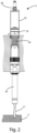
figure 2 shows a side view of a working unit; -
figure 3 shows a sectional view offigure 2 ; -
figure 4 shows a side view of a detail of the working unit offigure 2 ; and -
figure 5 shows a sectional view offigure 4 . - In the various figures, the similar parts will be indicated with the same reference numbers.
- An embodiment of the invention is described below by way of non-limiting example.
- With reference to
figures 1 ,2 , and3 , a drilling group 1 can be seen, on which a plurality of workingunits 2 are installed for drilling a panel P or a piece in general, using a tool, such as abit 21. - The drilling group 1 comprising a
support frame 11, having a plurality ofseats 12, each one of which houses a workingunit 2. - The drilling group 1 also comprises an
electric motor 13, to provide, by means of suitable transmission (not shown in the figure) installed within saidsupport frame 11, the driving force required to move said workingunits 2. - The drilling group 1 is also moved by possible further motor means in the direction of the piece to be working, to bring the tool, e.g., the
tip 21, into contact therewith. In particular, the drilling group 1 can pass from a non-operative position, in which the bit 21 (or the tool, in general) is not in contact with the piece, to a working position, in which the bit is in contact with the piece. - Each of said working
units 2 is equipped with aspecific bit 21 possibly of a different section according to the hole to be made. In particular, during drilling, thebit 21 of the selected workingunit 2 is placed in contact with a piece P to make one or more holes on one or more faces thereof. - Each working
unit 2 comprises apneumatic cylinder 22 vertically arranged, coupled to saidsupport frame 11 of the drilling group 1. Saidpneumatic cylinder 22 is delimited by abase 221 and ashell 222. - Compressed air is injected into the
pneumatic cylinder 22 through acompressed air inlet 28. In particular, in the embodiment in the figure, thecompressed air inlet 28 is obtained on saidbase 221. However, in other embodiments, thecompressed air inlet 28 can be placed in other alternative positions. For example, saidcompressed air inlet 28 can be obtained on saidshell 222.
cylinder pneumatic 22 also comprises a limit switch orabutment element 25, arranged inside it. In particular, with reference to the present embodiment, saidend stroke element 25 is arranged on the inner surface of saidshell 222, at an intermediate point of the length of thepneumatic cylinder 22. The function of saidend stroke element 25 will be better described below. - Furthermore, each working
unit 2 also comprises apiston 24, which is slidably movable inside saidpneumatic cylinder 22, between a retracted position, in which it preferably abuts saidbase 221 of saidpneumatic cylinder 22, and an extracted position, wherein saidpiston 24 exerts a mechanical stress on saidend stroke element 25. - Each working
unit 2 also comprises aspindle 29, associated with saidpiston 24. Thebit 21 of the workingunit 2 is fixed to one end of saidspindle 29. Thespindle 29 is, in use, driven in rotation by saidelectric motor 13. - Said
end stroke element 25 is arranged so that thepiston 24 can in particular be movable from said retracted position, in which it preferably abuts saidbase 221 of saidpneumatic cylinder 22, to said extracted position, in which saidpiston 24 exerts a mechanical stress on saidend stroke element 25. - Said
piston 24 is moved by injecting compressed air into thepneumatic cylinder 22 through saidcompressed air inlet 28. - The working
unit 2 also comprises return means, and in particular in the present embodiment, a returningspring 26, which is arranged inside of the pneumatic 22, between saidpiston 24 and saidshell 222. The returningspring 26 is configured to return saidpiston 24 from said extracted position to said retracted position. - With reference also to
figures 4 and5 , said workingunit 2 comprises a detectingdevice 23, arranged on saidend stroke element 25, so that, when saidpiston 24 is in said extracted position, it exerts stress on saidend stroke element 25, and said detectingdevice 23 is interposed between saidend stroke element 25 and saidpiston 24. - Said detecting
device 23 is made of piezoelectric material, and it is able to detect the force that saidpiston 24 exerts on saidend stroke element 25. - In a further embodiment said detecting
device 23 is arranged in an internal section of saidend stroke element 25. - In particular, said piezoelectric detecting
device 23 generates an electric signal following the mechanical stress received by thepiston 24 on saidend stroke element 25. In this way, the force that thepiston 24 exerts on thepneumatic cylinder 22 is detected, which, as will be better described below, is proportional to that thebit 21 exerts on the piece P to be drilled. - In alternative embodiments said detecting
device 23 can be a load cell or another type of force sensor. - Each drilling group 1 comprises one or a plurality of
control units 27, connected to a respective detectingdevice 23. Thecontrol unit 27 detects the electrical signal generated by said detectingdevice 23, to determine, as better explained below when the force between saidpiston 24 and saidend stroke element 25 is outside a predefinable range of values and/or if saidpiston 24 exerts mechanical stress on saidend stroke element 25. - The working
unit 2 described above operates as follows. - Before actually drilling a piece P, the working
unit 2 is selected which installs thebit 21 of interest, and compressed air is introduced through thecompressed air inlet 28 of the selected workingunit 2. This causes the passage of thepiston 24 of the workingunit 2 chosen from said retracted position, to said extracted position, in which, as mentioned, thepiston 24 exerts mechanical stress on saidend stroke element 25. At the same time, the returningspring 26 exerts a return force, having a direction opposite to the force exerted by the compressed air on thepiston 24. - Subsequently, the
spindle 29 is actuated and rotated. With it, thebit 21 is rotated, to drill the piece P. - To start drilling, the drilling group 1 is moved in the direction of the piece P, according to arrow A of
figure 1 , i.e., in the working position, so that saidbit 21 comes into contact and penetrates inside the piece to be machined, making the hole. - When the
drilling bit 21 is therefore in contact with a piece P, the resulting force R acting on the detectingdevice 23 of the selected workingunit 2 is given by the algebraic sum of the pneumatic pushing force Ppn , the returning force Ps of the returningspring 26 and the resistance force to the drilling opposed by the piece P, here indicated with Pm
- In normal working conditions, the resulting force R is included in a predefined interval between a respective lower threshold value, and a respective upper threshold value.
- When the
drilling bit 21 wears out, the resistance force to the drilling Pm opposed by the piece P gradually tends to increase, while the pneumatic pushing force Ppn and the returning force Ps of the returningspring 26 remains constant. - This results in a decreasing change in the resultant force R. When the resistance force to drilling Pm as said opposed by the piece P increases beyond a threshold value, it is necessary to replace the
drilling bit 21. -
Bits 21 of different diameters wear out at different times. In order to know when it is necessary to replace abit 21, the detectingdevice 23, which in the embodiment under examination is made of piezoelectric material, placed on saidend stroke element 25, generates an electric signal for measuring the resultant force R between Ppn , Ps , and Pm . - When a
bit 21 is excessively worn, the resulting force R becomes less than a predetermined lower threshold value, as the resistance force to drilling Pm increases. - The electric signal generated by the detecting
device 23 is processed by thecontrol logic unit 27 in order to emit an alarm or warning signal so that theworn bit 21 can be replaced. - In case of the
drilling bit 21 breaks, it is clearly unable to drill the piece P. Therefore, the contribution to the resulting force R due to the resistance force to drilling Pm is null, given that, since there is no drilling, there is no resistance to the drilling opposed by the piece P. - In the case of a
broken drilling bit 21, considering that the pneumatic pushing force Ppn and the returning force Ps of the returningspring 26 do not vary, the resultant R, exceeds a predetermined upper threshold value. - When this threshold value is exceeded, the detecting
device 23 emits an electric signal, processed by thecontrol logic unit 27 in order to emit an alarm or warning signal. - When the
piston 24 exerts mechanical stress with theend stroke element 25, thecontrol logic unit 27, by processing the electric signal emitted by the detectingdevice 23, is also capable of detecting the presence of thepiston 24, in order to provide evidence of the extracted position of thepiston 24. - An advantage of the present invention is that of allowing the replacement of specific machining tools, in particular drilling bits, as soon as they are subject to a degree of wear, such as to cause non-optimal machining and avoid a late or early replacement.
- Another advantage of the present invention is that of reducing the machining waste by detecting the breakage of specific tools.
- Yet another advantage of the invention is that of signaling incorrect positioning of the working tools.
- The present invention has been described for illustrative but not limitative purposes, according to its preferred embodiments, but it is to be understood that modifications and/or changes can be introduced by those skilled in the art without departing from the relevant scope as defined in the enclosed claims.
Claims (17)
- Working unit (2), for carrying out a working, such as drilling, milling, cutting or the like, on a piece (P) made of wood, plastic, fiberglass or the like, comprisinga working tool (21),characterized in that it comprises a detecting device (23) for detecting at least one input of the force (R) exerted by said tool (21) on said piece (P) for carrying out said working.
- Working unit (2) according to the preceding claim, characterizedin that it comprises:a pneumatic cylinder (22); anda piston (24) associated to said working tool (21);wherein said piston is movable inside said pneumatic cylinder (22), between a retracted position, in which said working tool (21) is excluded, and an extracted position, in which said working tool (21) is selected; andin that said detecting tool (23) is arranged so that when said piston (24) is in said extracted position, said detecting device (23) interferes with said piston (24) for detecting said at least one input of force (R) exerted by said tool (21) on said piece (P) during said working.
- Working unit (2) according to the preceding claim, characterizedin that it comprises an end stroke element (25) arranged inside said pneumatic cylinder (22), andin that when said piston (24) is in said extracted position, said end stroke element (25), said detecting device (23) and said piston (24) are arranged adjacent to each other, so that said detecting device (23) may detect the force of said piston (24) on said end stroke element (25).
- Working unit (2) according to the preceding claim, characterized
in that when said piston (24) is in said extracted position, it is in abutment with said detecting device (23), interposed between said end stroke element (25) and said piston (24). - Working unit (2) according to claims 3 or 4, characterized in that said detecting device (23) is arranged on said end stroke element (25).
- Working unit (2) according to any one of claims 2 - 4, characterized in that said detecting device (23) is coupled to said piston (24).
- Working unit (2) according to any one of the preceding claims, characterized in that said detecting device (23) is a piezoelectric sensor.
- Working unit (2) according to any one of claims 1-6, characterized in that said detecting device (23) is a load cell.
- Working unit (2) according to any one of the preceding claims, characterized in that said tool is a drilling bit (21).
- Working unit (2) according to any one of claims 2 - 9, characterized in that said force (R) is the resulting force acting on said detecting device (23), when said tool (21) carries out said working on said piece (P), wherein said force (R) is calculated according to the following equation:
 Ppn is the pneumatic pushing force that causes said piston (24) to move from said retracted position to said extracted position; andPm is the working resistance force opposed by the piece (P).
 - Working unit (2) according to any one of claims 2-9, characterized in that it comprises returning means, such as a returning spring (26), for returning said piston (24) from said extracted position to said retracted position.
- Working unit (2) according to the preceding claim, characterized in that said force (R) is the resulting force acting on said detecting device (23), when said tool (21) carries out said working on said piece (P), and said force (R) is calculated according to the following equation:
 Ppn is the pneumatic pushing force that causes said piston (24) to move from said retracted position to said extracted position;Ps is the returning force of said returning means (26); andPm is the working resistance force opposed by said piece (P).
 - Working unit (2) according to any one of the preceding claims, characterizedin that said detecting device (23) generates an electrical signal whose value is a substantially proportional function of the force (R) acting when said tool (21) carries out said working on said piece (P), andin that said detecting device (23) is connected to at least one control unit (27), configured for detecting said electric signal from said detecting signal (23).
- Working unit (2) according to the preceding claim, characterized in that said at least one control unit (27) is configured for detecting if said piston (24) exerts a mechanical stress on said limit switch element (25).
- Drilling group (1), comprising:a supporting frame (11) having one or more seats (12);one or more working unit (2), according to any one of the preceding claims, arranged as a matrix, each one housed in a respective seat (12) of said frame (11); andan electric motor (13), associated to said supporting frame (11), arranged to provide the motive force necessary for moving said working units (2).
- Drilling group (1) according to the preceding claim, when dependent on claim 2,
characterized in that said working units (2) are powered by compressed air for moving each piston (24) of each working unit (2) from said retracted position to said extracted position. - Method for detecting the operating state of a tool such as a drilling bit (21) and the like installed in a working unit (2) according to any one of claims 1-14, comprising the steps of:- detecting said electrical signal generated by the detecting device (23) of said working unit (2), whose value is a substantially proportional function of the force (R) acting when said tool (21) carries out said working on said piece (P); and- verifying if the amplitude of said electrical signal is between a first threshold value and a second threshold value, wherein said second threshold value is greater than said first threshold value;
wherein,- if the amplitude of said electrical signal is lower than said first threshold value, it is detected that said tool (21) is worn;- if the amplitude of said electrical signal is greater than said second threshold value, it is detected that said tool (21) is broken;- if the amplitude of said electrical signal is between said first threshold and said second threshold, then it is detected that said tool (21) is correctly operating.
Applications Claiming Priority (1)
| Application Number | Priority Date | Filing Date | Title |
|---|---|---|---|
| IT102021000028367A IT202100028367A1 (en) | 2021-11-08 | 2021-11-08 | Improved processing unit |
Publications (2)
| Publication Number | Publication Date |
|---|---|
| EP4177005A2 true EP4177005A2 (en) | 2023-05-10 |
| EP4177005A3 EP4177005A3 (en) | 2023-07-12 |
Family
ID=79831072
Family Applications (1)
| Application Number | Title | Priority Date | Filing Date |
|---|---|---|---|
| EP22204625.2A Pending EP4177005A3 (en) | 2021-11-08 | 2022-10-31 | Improved working unit |
Country Status (2)
| Country | Link |
|---|---|
| EP (1) | EP4177005A3 (en) |
| IT (1) | IT202100028367A1 (en) |
Family Cites Families (4)
| Publication number | Priority date | Publication date | Assignee | Title |
|---|---|---|---|---|
| DE4016480C2 (en) * | 1990-05-22 | 1994-07-14 | Gustav Weeke Maschinenbau Gmbh | Spindle unit for a drilling and milling machine |
| SE533114C2 (en) * | 2008-11-05 | 2010-06-29 | Atlas Copco Tools Ab | Spindle Unit |
| US10875138B1 (en) * | 2016-08-09 | 2020-12-29 | M4 Sciences Llc | Tool holder assembly for machining system |
| IT201800007340A1 (en) * | 2018-07-19 | 2020-01-19 | Operator unit for the processing of a panel and the related processing method. |
-
2021
- 2021-11-08 IT IT102021000028367A patent/IT202100028367A1/en unknown
-
2022
- 2022-10-31 EP EP22204625.2A patent/EP4177005A3/en active Pending
Also Published As
| Publication number | Publication date |
|---|---|
| EP4177005A3 (en) | 2023-07-12 |
| IT202100028367A1 (en) | 2023-05-08 |
Similar Documents
| Publication | Publication Date | Title |
|---|---|---|
| CN110297461B (en) | Abnormality detection device | |
| US6937942B2 (en) | Method and apparatus of detecting tool abnormality in a machine tool | |
| US4563897A (en) | Apparatus for monitoring tool life | |
| US4532599A (en) | Quality control method | |
| GB2414203A (en) | A method for operating a guided machine tool | |
| US20140360322A1 (en) | Sawing machine and method for controlling a sawing machine | |
| JP5937727B1 (en) | Tool wear evaluation device | |
| JP6722052B2 (en) | Multi-blade tool abnormality detection method | |
| CN111890124A (en) | On-line cutter monitoring system and method | |
| JP3291677B2 (en) | Method and apparatus for monitoring condition of machining blade for machine tool | |
| US4551808A (en) | Tool wear sensors | |
| MX2024004412A (en) | Method for monitoring the state of a gear cutting machine. | |
| Thangaraj et al. | Drill wear sensing and failure prediction for untended machining | |
| JP2007098523A (en) | Broach life determination method, broach quality control device, and broach processing device | |
| CN106217129A (en) | A kind of plate wear automatic-compensation method of forging a knife of contact Tool Broken Detect system | |
| GB2133881A (en) | Apparatus for monitoring tool life | |
| CN217749365U (en) | Spindle assembly | |
| Novak et al. | Reliability of the cutting force monitoring in FMS-installations | |
| KR20170100387A (en) | Machining device | |
| CN117428229A (en) | A CNC drilling machine and its control system | |
| JP2001277075A (en) | Load detecting method and device for cutting tool in machine tool | |
| EP4399502A1 (en) | Method for determining the wear state of a tool, and device for said method | |
| RU2496629C2 (en) | Method of control over multi-blade built-up tool cutting edges state | |
| KR20050030925A (en) | Ae signal monitoring system for surface defects and tool conditions on manufacturing process | |
| JPS61252052A (en) | Device for detecting abnormality of perforating tool |
Legal Events
| Date | Code | Title | Description |
|---|---|---|---|
| PUAI | Public reference made under article 153(3) epc to a published international application that has entered the european phase |
Free format text: ORIGINAL CODE: 0009012 |
|
| STAA | Information on the status of an ep patent application or granted ep patent |
Free format text: STATUS: THE APPLICATION HAS BEEN PUBLISHED |
|
| AK | Designated contracting states |
Kind code of ref document: A2 Designated state(s): AL AT BE BG CH CY CZ DE DK EE ES FI FR GB GR HR HU IE IS IT LI LT LU LV MC ME MK MT NL NO PL PT RO RS SE SI SK SM TR |
|
| PUAL | Search report despatched |
Free format text: ORIGINAL CODE: 0009013 |
|
| P01 | Opt-out of the competence of the unified patent court (upc) registered |
Effective date: 20230518 |
|
| AK | Designated contracting states |
Kind code of ref document: A3 Designated state(s): AL AT BE BG CH CY CZ DE DK EE ES FI FR GB GR HR HU IE IS IT LI LT LU LV MC ME MK MT NL NO PL PT RO RS SE SI SK SM TR |
|
| RIC1 | Information provided on ipc code assigned before grant |
Ipc: B27C 9/04 20060101ALI20230602BHEP Ipc: B27C 3/04 20060101ALI20230602BHEP Ipc: B23Q 17/09 20060101ALI20230602BHEP Ipc: B23B 39/24 20060101ALI20230602BHEP Ipc: B23B 39/16 20060101ALI20230602BHEP Ipc: B23Q 5/26 20060101AFI20230602BHEP |
|
| STAA | Information on the status of an ep patent application or granted ep patent |
Free format text: STATUS: REQUEST FOR EXAMINATION WAS MADE |
|
| 17P | Request for examination filed |
Effective date: 20240111 |
|
| RBV | Designated contracting states (corrected) |
Designated state(s): AL AT BE BG CH CY CZ DE DK EE ES FI FR GB GR HR HU IE IS IT LI LT LU LV MC ME MK MT NL NO PL PT RO RS SE SI SK SM TR |
|
| GRAP | Despatch of communication of intention to grant a patent |
Free format text: ORIGINAL CODE: EPIDOSNIGR1 |
|
| STAA | Information on the status of an ep patent application or granted ep patent |
Free format text: STATUS: GRANT OF PATENT IS INTENDED |
|
| INTG | Intention to grant announced |
Effective date: 20260216 |
|
| RAP1 | Party data changed (applicant data changed or rights of an application transferred) |
Owner name: HITECO S.R.L. |