EP4176911A1 - Modulare blutbehandlungsvorrichtung - Google Patents
Modulare blutbehandlungsvorrichtung Download PDFInfo
- Publication number
- EP4176911A1 EP4176911A1 EP22202646.0A EP22202646A EP4176911A1 EP 4176911 A1 EP4176911 A1 EP 4176911A1 EP 22202646 A EP22202646 A EP 22202646A EP 4176911 A1 EP4176911 A1 EP 4176911A1
- Authority
- EP
- European Patent Office
- Prior art keywords
- module
- blood treatment
- treatment device
- control unit
- modules
- Prior art date
- Legal status (The legal status is an assumption and is not a legal conclusion. Google has not performed a legal analysis and makes no representation as to the accuracy of the status listed.)
- Granted
Links
Images



Classifications
-
- A—HUMAN NECESSITIES
- A61—MEDICAL OR VETERINARY SCIENCE; HYGIENE
- A61M—DEVICES FOR INTRODUCING MEDIA INTO, OR ONTO, THE BODY; DEVICES FOR TRANSDUCING BODY MEDIA OR FOR TAKING MEDIA FROM THE BODY; DEVICES FOR PRODUCING OR ENDING SLEEP OR STUPOR
- A61M1/00—Suction or pumping devices for medical purposes; Devices for carrying-off, for treatment of, or for carrying-over, body-liquids; Drainage systems
- A61M1/14—Dialysis systems; Artificial kidneys; Blood oxygenators ; Reciprocating systems for treatment of body fluids, e.g. single needle systems for hemofiltration or pheresis
-
- A—HUMAN NECESSITIES
- A61—MEDICAL OR VETERINARY SCIENCE; HYGIENE
- A61M—DEVICES FOR INTRODUCING MEDIA INTO, OR ONTO, THE BODY; DEVICES FOR TRANSDUCING BODY MEDIA OR FOR TAKING MEDIA FROM THE BODY; DEVICES FOR PRODUCING OR ENDING SLEEP OR STUPOR
- A61M1/00—Suction or pumping devices for medical purposes; Devices for carrying-off, for treatment of, or for carrying-over, body-liquids; Drainage systems
- A61M1/14—Dialysis systems; Artificial kidneys; Blood oxygenators ; Reciprocating systems for treatment of body fluids, e.g. single needle systems for hemofiltration or pheresis
- A61M1/16—Dialysis systems; Artificial kidneys; Blood oxygenators ; Reciprocating systems for treatment of body fluids, e.g. single needle systems for hemofiltration or pheresis with membranes
- A61M1/1601—Control or regulation
-
- A—HUMAN NECESSITIES
- A61—MEDICAL OR VETERINARY SCIENCE; HYGIENE
- A61M—DEVICES FOR INTRODUCING MEDIA INTO, OR ONTO, THE BODY; DEVICES FOR TRANSDUCING BODY MEDIA OR FOR TAKING MEDIA FROM THE BODY; DEVICES FOR PRODUCING OR ENDING SLEEP OR STUPOR
- A61M1/00—Suction or pumping devices for medical purposes; Devices for carrying-off, for treatment of, or for carrying-over, body-liquids; Drainage systems
- A61M1/14—Dialysis systems; Artificial kidneys; Blood oxygenators ; Reciprocating systems for treatment of body fluids, e.g. single needle systems for hemofiltration or pheresis
- A61M1/16—Dialysis systems; Artificial kidneys; Blood oxygenators ; Reciprocating systems for treatment of body fluids, e.g. single needle systems for hemofiltration or pheresis with membranes
- A61M1/1621—Constructional aspects thereof
- A61M1/1635—Constructional aspects thereof with volume chamber balancing devices between used and fresh dialysis fluid
-
- A—HUMAN NECESSITIES
- A61—MEDICAL OR VETERINARY SCIENCE; HYGIENE
- A61M—DEVICES FOR INTRODUCING MEDIA INTO, OR ONTO, THE BODY; DEVICES FOR TRANSDUCING BODY MEDIA OR FOR TAKING MEDIA FROM THE BODY; DEVICES FOR PRODUCING OR ENDING SLEEP OR STUPOR
- A61M1/00—Suction or pumping devices for medical purposes; Devices for carrying-off, for treatment of, or for carrying-over, body-liquids; Drainage systems
- A61M1/14—Dialysis systems; Artificial kidneys; Blood oxygenators ; Reciprocating systems for treatment of body fluids, e.g. single needle systems for hemofiltration or pheresis
- A61M1/16—Dialysis systems; Artificial kidneys; Blood oxygenators ; Reciprocating systems for treatment of body fluids, e.g. single needle systems for hemofiltration or pheresis with membranes
- A61M1/1654—Dialysates therefor
- A61M1/1656—Apparatus for preparing dialysates
-
- A—HUMAN NECESSITIES
- A61—MEDICAL OR VETERINARY SCIENCE; HYGIENE
- A61M—DEVICES FOR INTRODUCING MEDIA INTO, OR ONTO, THE BODY; DEVICES FOR TRANSDUCING BODY MEDIA OR FOR TAKING MEDIA FROM THE BODY; DEVICES FOR PRODUCING OR ENDING SLEEP OR STUPOR
- A61M1/00—Suction or pumping devices for medical purposes; Devices for carrying-off, for treatment of, or for carrying-over, body-liquids; Drainage systems
- A61M1/34—Filtering material out of the blood by passing it through a membrane, i.e. hemofiltration or diafiltration
- A61M1/3413—Diafiltration
-
- G—PHYSICS
- G16—INFORMATION AND COMMUNICATION TECHNOLOGY [ICT] SPECIALLY ADAPTED FOR SPECIFIC APPLICATION FIELDS
- G16H—HEALTHCARE INFORMATICS, i.e. INFORMATION AND COMMUNICATION TECHNOLOGY [ICT] SPECIALLY ADAPTED FOR THE HANDLING OR PROCESSING OF MEDICAL OR HEALTHCARE DATA
- G16H20/00—ICT specially adapted for therapies or health-improving plans, e.g. for handling prescriptions, for steering therapy or for monitoring patient compliance
- G16H20/40—ICT specially adapted for therapies or health-improving plans, e.g. for handling prescriptions, for steering therapy or for monitoring patient compliance relating to mechanical, radiation or invasive therapies, e.g. surgery, laser therapy, dialysis or acupuncture
-
- G—PHYSICS
- G16—INFORMATION AND COMMUNICATION TECHNOLOGY [ICT] SPECIALLY ADAPTED FOR SPECIFIC APPLICATION FIELDS
- G16H—HEALTHCARE INFORMATICS, i.e. INFORMATION AND COMMUNICATION TECHNOLOGY [ICT] SPECIALLY ADAPTED FOR THE HANDLING OR PROCESSING OF MEDICAL OR HEALTHCARE DATA
- G16H40/00—ICT specially adapted for the management or administration of healthcare resources or facilities; ICT specially adapted for the management or operation of medical equipment or devices
- G16H40/60—ICT specially adapted for the management or administration of healthcare resources or facilities; ICT specially adapted for the management or operation of medical equipment or devices for the operation of medical equipment or devices
- G16H40/63—ICT specially adapted for the management or administration of healthcare resources or facilities; ICT specially adapted for the management or operation of medical equipment or devices for the operation of medical equipment or devices for local operation
-
- A—HUMAN NECESSITIES
- A61—MEDICAL OR VETERINARY SCIENCE; HYGIENE
- A61M—DEVICES FOR INTRODUCING MEDIA INTO, OR ONTO, THE BODY; DEVICES FOR TRANSDUCING BODY MEDIA OR FOR TAKING MEDIA FROM THE BODY; DEVICES FOR PRODUCING OR ENDING SLEEP OR STUPOR
- A61M2205/00—General characteristics of the apparatus
- A61M2205/70—General characteristics of the apparatus with testing or calibration facilities
Definitions
- the present invention relates to a modular blood treatment device according to the preamble of claim 1, in particular to a modular dialysis device, preferably a modular hemodiafiltration device, with a plurality of modules that are designed to be detachable, in particular mechanically, electrically, electronically, for carrying out a blood treatment on a patient to be coupled to one another fluid-mechanically and/or hydraulically, a main control unit which is designed to control the modules coupled to one another for carrying out the blood treatment, sensors and actuators.
- U.S. 2011/0 189 048 A1 discloses a blood treatment device in the form of a modular dialysis system having a user interface module, a water treatment module and a dialysis module.
- a traditional dialysis system is modularized to make it easier to transport, making it easier to carry out dialysis treatments away from dialysis centers at home.
- the dialysis system corresponds to U.S. 2011/0 189 048 A1 a conventional dialysis system, the handling and safety of which is adapted to use by specialist personnel.
- the object of the present disclosure is therefore to provide a modular blood treatment device that enables improved safety.
- a modular blood treatment device has several modules, a main control unit, sensors and actuators.
- the modules are designed to be detachably coupled to one another in order to carry out a blood treatment on a patient.
- Coupled means in particular that there is a mechanical, electrical, electronic, fluid-mechanical and/or hydraulic connection.
- “Detachable” means in particular that the modules coupled to one another can be separated or decoupled from one another in a non-destructive manner, preferably without tools.
- a blood treatment device has a blood circuit.
- a blood treatment device preferably has at least one further fluid circuit, for example a dialysis fluid circuit.
- the blood circuit is connected to the patient via connections.
- the term fluid system can be used when reference is made to the blood circuit and/or the at least one further fluid circuit.
- the main control unit is designed to control the modules coupled to one another in order to carry out the blood treatment.
- the sensors can be designed, for example, to measure pressure, temperature and/or conductivity of the blood or fluid in the blood circuit and/or to detect blood and/or air in the blood circuit and/or the fluid circuit.
- the actuators can be designed, for example, as a valve in the blood circuit or the fluid circuit or as a pump in the blood circuit or the fluid circuit.
- a heating element or a heating element can also represent an actuator.
- At least two of the modules are designed as self-control modules.
- Each of the at least two automatic control modules has at least the following components: at least one of the actuators and at least one module control unit.
- the automatic control modules can each also have at least one of the sensors. These components of a respective automatic control module are connected to one another in particular in such a way that data can be exchanged between the components.
- the self-control modules can have lines of the blood circuit and/or the at least one fluid circuit.
- the blood treatment device according to the disclosure is designed in such a way that the at least one actuator (and in particular possibly also a sensor) of one of the self-control modules has access to lines of other modules of the blood treatment device, so that the corresponding self-control module does not have to have its own lines.
- the respective module control unit is designed to be able to control the at least one actuator of the same automatic control module, in particular using data from the at least one sensor of the same automatic control module. Furthermore, the respective module control unit is designed to be able to determine a predetermined change in status of the automatic control module belonging to the respective module control unit.
- the predetermined state change is, for example, an interruption or fault in the connection between one of the module control units and the at least one actuator of the same automatic control module or an interruption or fault in the connection between one of the module control units and the at least one sensor of the same automatic control module.
- the module control units are designed in such a way that, upon detection of the predetermined change in state, they generate a corresponding Can send module status change message directly to the at least one other module control unit, and accordingly to be able to receive a module status change message directly from the at least one other module control unit.
- Directly means in particular that the at least two module control units are designed to mutually send module status change messages and receive them accordingly without interposing the main control unit or involving it in the sending and receiving of a module status change message.
- module control units are designed to communicate directly with one another.
- the at least two module control units are designed in such a way that upon receipt of a module status change message from the at least one other module control unit, they instruct the at least one actuator of the same automatic control module, i.e. the at least one actuator of the automatic control module whose module control unit has received the module status change message, to carry out a predetermined action .
- the "predetermined action” may be implemented in the form of a predetermined single operation or in the form of a series of operations (in the form of a program or routine).
- the configuration according to the disclosure advantageously creates a modular blood treatment device which can react quickly to certain changes in the status of individual modules.
- the predetermined action instructed by at least one of the module control units can be switching the at least one sensor and/or the at least one actuator of the same automatic control module into a zero position and/or enabling a Bypass line of the same self-control module for a fluid system, ie for the blood circuit and/or the at least one further fluid circuit of the blood treatment device.
- the zero position can correspond to the pump being switched off. If the actuator is a valve, the zero position can correspond to a closed state of the valve. The zero position of the at least one sensor can correspond to a switched-off state of the sensor.
- the bypass line is preferably a component of that self-control module whose module control unit instructs the predetermined action. However, it is also possible that the bypass line is a component of another module.
- Opening a bypass line means in particular that a line through which blood and/or another fluid such as dialysis fluid flows in normal operation is blocked and the blood and/or other fluid is conducted exclusively via the bypass line. However, it is also within the meaning of the disclosure to only partially block the line used in normal operation and to conduct only part of the blood and/or other fluid via the bypass line.
- a sensor and/or actuator is switched to a zero position and/or a bypass line is released, it is advantageously possible, in the event of a predetermined module state change of a control module, to quickly put other modules into a standby state without immediately shutting down the entire blood treatment device must.
- At least one of the self-control modules can have a monitoring sensor as a further component in addition to the at least one sensor.
- the module control unit of the self-control module with the monitoring sensor can be a Have execution unit and a monitoring unit.
- the at least one sensor of the self-control module can be connected to the execution unit and the monitoring sensor can be connected to the monitoring unit.
- the module control unit can be designed to recognize the predetermined module status change of the associated automatic control module by comparing data from the execution unit and the monitoring unit.
- the monitoring computer based on the monitoring sensor arrives at the same results or data as the execution computer based on the sensor. If there is a predetermined module status change, the data of the execution computer and the monitoring computer differ from one another, so that the predetermined module status change can be recognized.
- a self-control module equipped with a monitoring unit can be designed in such a way that the monitoring unit is not only connected to the corresponding monitoring sensor, but also to the at least one sensor. It is thus possible for the monitoring calculation to carry out the same calculations as the execution computer on the one hand on the basis of the monitoring sensor and to others such as the execution computer on the basis of the at least one sensor, so that by comparing these two calculations of the monitoring computer with the corresponding calculation of the execution computer by means of the module control unit or by means of the monitoring computer of the module control unit it can be determined whether the at least one sensor or the execution computer is functioning properly.
- the design of the at least one sensor and the design of the monitoring sensor of the self-control module can differ and/or the design of a microprocessor of the execution unit and the design of a microprocessor of the monitoring unit can differ. Different designs can make it possible to detect not only random but also systematic failures or impairments.
- At least one of the self-control modules may store calibration data for at least a portion of the components of the same self-control module.
- at least one calibration curve in particular coefficients of a calibration curve, for example a polynomial, can be stored as calibration data.
- the storage of calibration data in the self-control module can advantageously simplify the calibration of the self-control module.
- the calibration of the individual self-control module or its components can be made possible or simplified independently of the blood treatment device.
- At least one of the self-control modules can store at least one threshold value for at least some of the components of the same self-control module, and the module control unit of the same self-control module can be configured to change the predetermined module state of the associated self-control module by comparing data from at least one of the components of the same To recognize self-control module and the at least one threshold.
- threshold values rapid detection of the predetermined module state change can advantageously be made possible.
- the main control unit can be embodied as a separate module in the form of a main control module and the blood treatment device can have multiple modules necessary for carrying out a blood treatment of a patient, so that the blood treatment device is suitable for the simultaneous blood treatment of multiple patients.
- the main control module can be designed to be able to control the simultaneous blood treatment of several patients.
- the provision of a main control module can simplify the simultaneous treatment of multiple patients and reduce the cost of simultaneous treatment of multiple patients.
- the blood treatment device can have an operating and display module that is designed to display data from at least individual modules of the treatment device, to receive commands from a user and to forward the commands to the main control unit and/or directly to at least individual modules of the treatment device .
- the operating and display module can be designed to have the main control unit itself. By providing a separate operating and display module, it is easily possible to adapt the human-machine interface to new standards, if necessary, without having to rework the entire blood treatment device.
- an operating and display module can be designed in such a way that it can be used, in particular simultaneously, for a number of treatment devices.
- the blood treatment device can have a calibration module which has at least one reference measuring device which is designed to enable a comparison with at least one of the sensors.
- a calibration module can advantageously a Calibration of individual modules can be simplified.
- such a calibration can be carried out in a state in which the module to be calibrated is not connected to any other modules or not to all modules necessary for blood treatment (for example before assembly, when a module is replaced).
- the maintenance effort (maintenance time and/or costs) of the blood treatment device according to the disclosure can be kept low by means of the calibration module.
- the calibration module is designed in particular in such a way that it is not part of the blood treatment device during a treatment.
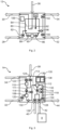
- FIG. 1 shows a schematic view of a blood treatment device 2 according to the disclosure, a power supply 4, a water supply and disposal 6, a central concentrate supply 8 and a patient 10.
- the blood treatment device 2 has a water treatment module 12 , a dialysis liquid treatment module 14 , a balancing module 16 , a dialysis liquid connection module 18 , a hemodiafiltration module 20 , a blood connection module 22 , a dialyzer 24 and a main control module 26 .
- the water treatment module 12 has interfaces (connections or ports, not shown) to which a fresh water line and a waste water line can be connected in order to be connected to the water supply and disposal 6, so that the water treatment module 12 draws a fresh water flow 28 and a waste stream 30 can discharge. Furthermore, the water treatment module 12 has interfaces (not shown in more detail) via which treated water can be delivered to the dialysis liquid treatment module 14 in a main flow 32 and in a side flow 34 . The water treatment module 12 can receive a dialysate stream 36 from the balancing module 16 via an interface (not shown in detail).
- the dialysis fluid treatment module 14 has interfaces (not shown in detail) via which the main flow 32 and the secondary flow 34 of the water treated by the water treatment module 12 can be received. Furthermore, the dialysis fluid preparation module 14 has interfaces (not shown in detail) via which the Dialysis fluid processing module 14 can receive a basic concentrate stream 38 and an acidic concentrate stream 40 from corresponding (not shown) canisters or cartridges. The dialysis fluid preparation module 14 can receive an acidic concentrate stream 42 from the central concentrate supply 8 via at least one interface (not shown in detail). The dialysis fluid preparation module 14 can deliver a dialysis fluid stream 44 to the balancing module 16 via an interface (not shown in detail).
- the balancing module 16 has an interface (not shown in detail) via which the flow of dialysis fluid 44 can be received by the dialysis fluid preparation module 14 .
- the balancing module 16 can also deliver a flow of dialysis liquid to the hemodiafiltration module 20 via an interface (not shown in detail).
- the balancing module 16 has interfaces (not shown in detail) via which a dialysate stream 50 can be received by the dialysis fluid connection module 18 and the dialysate stream 36 can be delivered to the water treatment module 12 .
- the dialysis liquid connection module 18 has an interface (not shown in more detail) via which a flow of dialysis liquid 52 can be delivered to the dialyzer 24 . Furthermore, the dialysis liquid connection module 18 has an interface (not shown in detail) via which a flow of dialysis liquid 54 can be received by the hemodiafiltration module 20 . The dialysis fluid connection module 18 can receive a dialysate stream 56 from the dialyzer 24 via interfaces (not shown in detail) and deliver the dialysate stream 50 to the balancing module 16 . Furthermore, the dialysis fluid connection module 18 has an interface (not shown in detail) via which a stream 58 of excess substituate can be received by the hemodiafiltration module 20 .
- the hemodiafiltration module 20 has interfaces (not shown in detail) via which the dialysis liquid flow 48 from the balancing module 16 can be received, the flow of dialysis fluid 54 can be delivered to the dialysis fluid connection module 18 and a substituate flow 60 can be delivered to the blood connection module 22 . Furthermore, the hemodiafiltration module 20 has an interface (not shown in more detail) via which the stream 58 of excess substituate can be delivered to the dialysis liquid connection module 18 .
- the blood connection module 22 has interfaces (not shown in detail) via which a flow 64 of untreated blood (arterial blood) can be received from the patient 10 and a flow 66 of untreated blood can be delivered to the dialyzer 24 .
- the blood connection module 22 can receive a stream 68 of treated blood from the dialyzer 24 and deliver a stream 70 of treated blood (venous blood) to the patient 10 via interfaces (not shown in detail).
- the blood connection module 22 has an interface (not shown in more detail) via which the substituate flow 60 can be received by the hemodiafiltration module 20 .
- the dialyzer 24 has interfaces via which the dialysis liquid flow 52 can be received by the dialysis liquid connection module 18 and the dialysate flow 56 can be delivered to the dialysis liquid connection module 18 . Furthermore, the dialyzer 24 has interfaces via which the flow 66 of untreated blood can be received by the blood connection module 22 and the flow 68 of treated blood can be delivered to the blood connection module 22 .
- the main control module 26 can be connected to the power supply 4 via an electrical line 72 .
- the blood treatment device 2 has lines 74 by means of which the main control module 26 can supply the modules 12 to 22 with electrical current or electrical power.
- the lines 74 are also designed to be able to exchange data (commands from the main control module 26 to one of the modules 12 to 22, feedback from one of the modules 12 to 22 to the main control module 26) between the main control module 26 and the modules 12 to 22.
- the main control module 26 is also designed as an operating and display module according to the disclosure and has a touch-sensitive screen 76 and input keys 78 .
- the main control module 26 can also be designed without an integrated screen and/or without integrated input keys.
- the main control module 26 can be designed in such a way that a separate screen and/or a separate keyboard can be connected.
- the screen 76 and/or the input keys 78 can be embodied in an operating and display module embodied separately from the main control module 26 .
- the individual modules 12 to 22 are described below in a state during a blood treatment, in which the modules 12 to 26 are connected to one another to form the blood treatment device 2, and the blood treatment device 2 with the power supply 4, the water supply and disposal 6 , the central concentrate supply 8 and the patient 10 is connected.
- the water treatment module 12 For a blood treatment, water must first be degassed and tempered.
- the water treatment module 12 includes a feed tank 80 (water tank).
- the fresh water flow 28 can be conducted from the water supply and disposal 6 into the supply tank 80 via a valve 82 and a pressure-reducing valve (not shown).
- Two level sensors (not shown) determine the filling level 84.
- a pump 86 is used for degassing, which allows the water to circulate in the supply tank 80 and, in the process, generates a vacuum that is monitored using a pressure sensor 88, as a result of which dissolved gases can escape by means of a degassing chamber 90.
- the supply tank 80 there is also a heat exchanger 92 for energy recovery from the dialysate stream 36.
- the warm dialysate flows via the dialysis liquid module 18 and the balancing module 16 into the heat exchanger 92, where it gives off heat, and then as a waste water stream into the drain.
- a heating element 94 located in the supply tank 80 is also used to heat the water and a temperature sensor 96 are used.
- the temperature of the treated water can be measured with the temperature sensor 96 , which after the temperature sensor 96 is fed to the main stream 32 on the one hand and to the secondary stream 34 on the other.
- the main flow 32 of treated water and the secondary flow 34 of treated water can be prevented via valves 100 and 102 .
- the valves 82, 100 and 102, the pump 86 and the heating element 94 represent actuators according to the disclosure.
- the pressure sensor 88 and the temperature sensor 96 represent sensors according to the disclosure Valves 82, 100 and 102, the pump 86, the pressure sensor 88, the heating element 94 and the temperature sensor 96 is connected.
- the module control unit 106 is connected to the main control module 26 via one of the lines 74 .
- the water treatment module 12 is designed as a self-control module according to the disclosure.
- the module control unit 106 controls or regulates the pump 86 on the basis of the negative pressure measured by the pressure sensor 88 in order to achieve a predetermined target negative pressure.
- the module control unit 106 controls the heating element 94 based on the temperatures measured by the temperature sensor 96 in order to achieve a predetermined target temperature.
- the main control module 26 When carrying out a blood treatment, the main control module 26 specifies the predetermined target negative pressure and the target temperature for the module control unit 106 of the water treatment module 12 .
- the main control module 26 does not have direct access to the pump 86 and the heating element 94 and does not issue any instructions regarding, for example, a speed of the pump 86 or a heat output of the heating element 94.
- the main stream 32 of the treated water is in a Mixing chamber 108 first added a basic component (e.g. sodium bicarbonate).
- the basic component may be obtained from a concentrate canister (not shown) (see basic concentrate stream 38) containing the basic component in a pre-dissolved state (e.g., dissolved sodium bicarbonate).
- the basic component can be obtained from a cartridge 110 containing the basic component in a powdered state (e.g., powdered sodium bicarbonate).
- the side stream 34 of the treated water is first mixed with the powdered basic component before the mixture of the side stream 34 of the treated water and the basic component is mixed in the mixing chamber 108 mixed with the main stream 32 of treated water.
- the basic component is conveyed to the mixing chamber 108 via a pump 111 arranged upstream of the mixing chamber 108 .
- the water mixed with the basic component is then fed into a mixing chamber 112, in which an acidic component is added.
- the acidic component can be obtained from different sources.
- the acidic component can be obtained from a concentrate canister (not shown) and, on the other hand, the central concentrate supply 8 can supply the dialysis fluid preparation module 14 with the acidic component.
- Several lines can be provided for connection to the central concentrate supply 8 in order to be able to obtain concentrates of different compositions if required. Irrespective of the source of supply, the acidic component is conveyed to the mixing chamber 112 via a pump 113 arranged upstream of the mixing chamber 112 .
- the conductivity sensors 114 and 116 are used to determine the composition of the dialysis fluid.
- the conductivity sensor 114 measures the conductivity after adding the basic component (sodium bicarbonate) to the deaerated and heated water.
- the Conductivity sensor 116 determines the total conductivity after adding the acidic component. Since an incorrectly composed dialysis fluid can possibly harm the patient 10, the dialysis fluid preparation module 14 has a further conductivity sensor 118, which also determines the overall conductivity.
- Conductivity sensor 118 constitutes a monitoring sensor in accordance with the disclosure with respect to conductivity sensor 116.
- the dialysis fluid preparation module 14 has a valve 120 for controlling the inflow of the main stream 32 of the treated water, a valve 122 for controlling the inflow of the side stream 34 of the treated water, a valve 124 for controlling the inflow of the basic concentrate stream 38, a valve 126 for controlling the Inflow of the acidic concentrate stream 40, a valve 128 for controlling the inflow of the acidic concentrate stream 42 from the central concentrate supply 8 and a valve 130 for controlling the outflow of the dialysis fluid stream 44.
- a temperature sensor 132 is connected upstream of the conductivity sensors 114 .
- a temperature sensor 133 is connected upstream of the conductivity sensors 116 and 118 and a temperature sensor 134 is connected downstream.
- the temperature sensor 134 represents a monitoring sensor according to the disclosure with respect to the temperature sensor 133.
- valve 100 configured in the water treatment module 12 and the valve 120 configured redundantly in the dialysis fluid treatment module 14 in the main stream 32 of the treated water
- valve 102 configured in the water treatment module 12
- valve 122 configured redundantly in the dialysis fluid treatment module 14 in the bypass 34 of the treated water
- the pumps 111 and 113 and the valves 120 to 130 represent actuators according to the disclosure.
- the conductivity sensors 114 to 118 and the temperature sensors 132, 133 and 134 represent sensors according to the disclosure connected to the pumps 111 and 113, the valves 120 to 130, the conductivity sensors 114 to 118 and the temperature sensors 132, 133 and 134.
- the module control unit 135 is connected to the main control module 26 via one of the lines 74 .
- the dialysis fluid preparation module 14 is designed as a self-control module according to the disclosure.
- the module control unit 135 has an execution unit 136 which controls the pump 111 and the valves 120 to 124 on the basis of the conductivity measured by the conductivity sensor 114 in order to achieve a predetermined target conductivity of the basic mixture.
- the execution unit 136 of the module control unit 135 controls or regulates the pump 113 and the valves 126 and 128 on the basis of the conductivity measured by the conductivity sensor 116 in order to achieve a predetermined target conduct
- the main control module 26 specifies the predetermined target conductivity of the alkaline mixture and the target conductivity of the dialysis liquid to the module control unit 135 of the dialysis liquid preparation module 14 .
- the blood treatment device 2 can also be designed in such a way that the main control module specifies target concentrations (e.g. of hydrogen carbonate and sodium) for the dialysis liquid preparation module 14 and the module control unit 135 of the dialysis liquid preparation module 14 then converts the target concentrations into the target conductivities.
- target concentrations e.g. of hydrogen carbonate and sodium
- the module control unit 135 of the dialysis fluid preparation module 14 also has a monitoring unit 138, which is connected via lines (not shown) like the execution unit 136 with the pumps 111 and 113, the valves 120 to 130, the conductivity sensors 114 to 118 and the temperature sensors 132 to 134 and which performs the same calculation processes as the execution unit 136 when performing a blood treatment.
- the monitor unit 138 is connected to the execution unit 136 via a line (not shown).
- the monitoring unit 138 is designed to compare the results of its own calculations with corresponding results of the execution unit 136, so that the module control unit 135 can register whether the calculations of the execution unit 136 and the monitoring unit 138 match.
- the dialysis fluid flow 44 coming from the dialysis fluid preparation module 14 is conducted by means of a dialysis fluid pump 140 via dialysis fluid-side parts of two balancing chambers 142 and 144 to a dialysis fluid filter 146, from which the filtered dialysis fluid is fed to the dialysis fluid flow 4 8 to that Hemodiafiltration module 20 is supplied.
- the dialysate of the dialysate stream 50 coming from the dialysis liquid connection module 18 is conveyed by a dialysate pump 148 via parts of the balance chambers 142 and 144 on the dialysate side to the dialysate stream 36 .
- part of the dialysate of the dialysate flow 50 coming from the dialysis liquid connection module 18 can be conveyed via an ultrafiltrate pump 150 past the dialysate-side parts of the balance chambers 142 and 144 directly to the dialysate flow 36.
- the dialysis fluid filter 146 is connected to the dialysate flow 36 via a valve 156 in such a way that the portion of the dialysis fluid in the dialysis fluid flow 44 retained by the dialysis fluid filter 146 can be fed to the dialysate flow 36 by opening the valve 156 .
- the retained by the dialysis fluid filter 146 part of the dialysis fluid of the dialysis fluid flow 44 is open valve 156 upstream of the pumps 148 and 150 connected in parallel to one another are introduced into the dialysate stream 36 . In normal operation, valve 156 is closed.
- the balancing module 16 has valves 152 and 154, which are switched in a known manner (see, for example, DE 10 2017 125 962 A1 ). Furthermore, the balancing module 16 has a valve 158, by means of which the inflow to the flow of dialysis liquid 48 can be controlled. A sensor (not shown) is provided for each balancing chamber 142 or 144 to monitor or detect a diaphragm position.
- the dialysis fluid pump 140, the valves 152, the dialysate pump 148, the ultrafiltrate pump 150 and the valves 154 and 158 represent actuators according to the disclosure.
- the balancing module 16 has a module control unit 160, which is connected via lines (not shown) to the dialysis fluid pump 140, the valves 152 , dialysate pump 148, ultrafiltrate pump 150 and valves 154 and 158. Furthermore, the module control unit 160 is connected to the main control module 26 via one of the lines 74 .
- the balancing module 16 is designed as a self-control module according to the disclosure.
- the module control unit 160 controls the dialysis fluid pump 140, the valves 152, the dialysate pump 148, the ultrafiltrate pump 150 and the valves 154 and 158 according to a flow rate of the dialysis fluid specified by the main control module 26 and corresponding to an ultrafiltration volume.
- FIG 5 shows a schematic detailed view of the dialysis fluid connection module 18.
- the dialysate stream 56 coming from the dialyzer 24 is routed to the dialysate stream 50 leading to the balancing module 16.
- the dialysis liquid stream 54 coming from the hemodiafiltration module 20 can flow in the dialysis liquid connection module 18 into the dialysis liquid stream 52 leading to the dialyzer 24 and/or over a bypass line 169 can be fed into the dialysate stream 50 leading to the balancing module 16 .
- the stream 58 of excess substituate coming from the hemodiafiltration module 20 can be fed into the dialysate stream 50 leading to the balancing module 16 in the dialysis liquid connection module 18 .
- the dialysis liquid connection module 18 has valves 162 , 163 and 164 .
- the inflow from the dialysis liquid flow 54 to the dialysate flow 50 or the flow through the bypass line 169 can be controlled by means of the valve 162 .
- the inflow from the dialysis liquid flow 54 to the dialysis liquid flow 52 can be controlled by means of the valve 163 .
- the inflow from the dialysate flow 56 to the dialysate flow 50 can be controlled by means of the valve 164 . If the valve 163 is completely closed and at the same time the valve 162 is opened, in particular completely, the dialysis liquid flow 54 can be completely fed into the dialysate flow 50 via the bypass line 169 .
- a blood leak detector 165 and optionally a UV sensor 166, a temperature sensor 167 and/or a conductivity sensor 168 are arranged downstream of the valve 164 .
- the valves 162 to 164 represent actuators according to the disclosure.
- the blood leak detector 165, the optional UV sensor 166, the optional temperature sensor 167 and/or the optional conductivity sensor 168 represent sensors according to the disclosure.
- the dialysis liquid connection module 18 has a module control unit 170, which has (not shown) lines with the valves 162 to 164, the blood leak detector 165 and optionally with the UV sensor 166, the temperature sensor 167 and / or the conductivity sensor 168 is connected. Furthermore, the module control unit 170 is connected to the main control module 26 via one of the lines 74 .
- the dialysis liquid connection module 18 is designed as a self-control module according to the disclosure.
- the dialysis liquid connection module 18 can control the valves 162 to 164 according to a specification from the main control module 26 and, for example, activate the bypass line 169 on instruction and stop the supply of dialysis liquid to the dialyzer 24 .
- the module control unit 170 is formed that to activate the bypass line 169 and to stop the supply of dialysis liquid to the dialyzer 24 if the blood leak detector 165, the optional UV sensor 166, the optional temperature sensor 167 and/or the optional conductivity sensor 168 each or collectively measure one or a predetermined number of values which implies a malfunction of the dialyzer 24 and/or a complication in the patient 10 .
- the module control unit 170 detects the malfunction of the dialyzer 24 and/or the complication in the patient 10 by comparing the measured value and/or the predetermined set of measured values with one or more corresponding reference values stored in the module control unit 170 or in the main control module 26 and determining a predetermined deviation from the reference value or values.
- the dialysis fluid of the dialysis fluid stream 48 can be routed to a hemodiafiltration filter 172, from which the filtered dialysis fluid as a substituate is routed via a valve 178 to the substituate stream 60 and via a valve 176 can be passed to stream 58 of excess substituate.
- the portion of the dialysis fluid coming from the dialysis fluid flow 48 that is held back by the hemodiafiltration filter 172 can be routed to the dialysis fluid flow 54 via a valve 174 .
- valves 164 of the dialysis fluid connection module 18 and 174 of the hemodiafiltration module 20 it is alternatively possible to provide only one of the two valves 164 and 174.
- the valves 174-178 represent actuators in accordance with the disclosure.
- the hemodiafiltration module 20 includes a module control unit 180 which is connected to the valves 174-178 via lines (not shown). Furthermore, the module control unit 180 is connected to the main control module 26 via one of the lines 74 .
- the hemodiafiltration module 20 is as disclosed self-control module formed. The hemodiafiltration module 20 can control the valves 174 to 178 in accordance with a specification from the main control module 26 and, for example, stop the supply of substituate to the patient 10 on instruction.
- valve 178 can be closed and the valve 176 opened so that the substituate is fed into the stream 58 excess substituate and flows to the dialysis fluid connection module 18 where it is fed into the dialysate stream 50.
- the blood connection module 22 is designed to be connected to the patient 10 via hoses (not shown).
- the untreated blood of the flow 64 is supplied to the untreated blood flow 66 via a valve or a tube occlusion clamp 182, a hematocrit sensor 184, an arterial pressure sensor 186 and a blood pump 188.
- the dialyzer 24 After passing through the dialyzer 24, of any known design, the now treated blood flows in stream 68 back to the blood connector module 22 where it is treated into stream 70 via a venous pressure sensor 190, an air and blood detector 192, and a valve or tubing occlusion clamp 194 Blood and thus to the patient 10 flows.
- substituate can be introduced from the substituate stream 60 via a substituate pump 196 into the stream 70 of treated blood.
- the blood connection module 22 has an anticoagulant pump 198 by means of which an anticoagulant can be introduced into the blood downstream of the blood pump 188 .
- the valves or hose shut-off clamps 182 and 194 and the pumps 188, 190, 196 and 198 represent actuators according to the disclosure.
- the sensors 184, 186, 190 and 192 represent sensors according to the disclosure.
- the blood connection module 22 has a module control unit 200, which has (not shown) lines with the valves 182 and 194, with the pumps 188, 190, 196 and 198 and to sensors 184, 186, 190 and 192. Furthermore, the module control unit 200 is connected to the main control module 26 via one of the lines 74 .
- the blood connection module 22 is designed as a self-control module according to the disclosure.
- the blood connection module 22 can control the valves 182 and 194 and/or the pumps 188, 190, 196 and 198 according to a specification from the main control module 26 and, for example, on instruction, stop the supply of substituate to the patient 10 or stop the withdrawal of blood.
- their module control units 106, 135, 160, 170, 180 and 200 can register predetermined status changes of the respective module 12, 14, 16, 18, 20 and 22 and among themselves without involving the main control module 4 communicate using module state change messages according to the disclosure.
- the module control units 106, 135, 160, 170, 180 and 200 can also be designed in such a way that they communicate with one another via the main control module 4.
- a corresponding module status change message is sent from the module control unit 135 of the dialysis liquid preparation module 14 to the module control unit 106 of the water treatment module 12, which then, as a predetermined action, energizes the heating element 94 (i.e., decreases/increases the power supplied to the heating element 94) to reach the predetermined temperature.
- the module status change message from the module control unit 135 can also be sent in parallel to the module control unit 106 of the water treatment module 12 to the module control unit 170 of the dialysis liquid connection module 18, which then, as a predetermined action, closes the valve 163, opens the valve 162, the dialysis liquid that is not at the right temperature through the bypass line 169 derives and thus the supply of the dialysis fluid that is not at the correct temperature to the dialyzer 24 is prevented.
- the respective module control units can register status changes in the form of deviations of measurement data from predetermined values or from predetermined tolerance ranges, corresponding predetermined values/tolerance ranges for the sensor or sensors belonging to the respective automatic control module are on those automatic control modules which have at least one sensor. stored on the respective module control unit.
- the state changes may be categorized. For example, a first category of status changes can be provided, which requires an immediate shutdown of the individual self-control modules of the treatment device 2, and a second category can be provided, which only requires individual self-control modules to wait.
- a predetermined action is stored for each category, which is carried out when a status change occurs in the corresponding category.
- the monitoring unit 138 of the dialysis fluid preparation module 14 registers that the measured values of the conductivity sensors 116 and 118 deviate from one another, this means that the monitoring of the composition of the dialysis fluid, which is highly relevant for the survival of the patient 10, is faulty. Because of the relevance monitoring of the composition, the treatment would have to be stopped and this change in status of the dialysis liquid preparation module 14 would consequently trigger a module status change message of the first category, whereupon the dialysis liquid would be immediately diverted from the module control unit 170 of the dialysis liquid connection module 18 through the bypass line 169 and the substitute from the module control unit 180 of the hemodiafiltration module 20 would be before the entire blood treatment device 2 is then shut down.
- the monitoring unit 138 of the dialysis fluid preparation module 14 is also designed in such a way that it triggers a module state change message of the first category if the temperature measured by the temperature sensor 133 differs from the temperature measured by the temperature sensor 134 . Also due to this module status change message of the first category, the dialysis fluid would be diverted from the module control unit 170 of the dialysis fluid connection module 18 through the bypass line 169 and the substitute from the module control unit 180 of the hemodiafiltration module 20 before the entire blood treatment device 2 is then shut down or at least put into a standby mode.
- the module control unit 106 of the water treatment module 12 can only report a module status change of the second category. Accordingly, the dialysis fluid would initially be derived from the module control unit 170 of the dialysis fluid connection module 18 through the bypass line 169 and from the module control unit 180 of the hemodiafiltration module 20 the substituate, but since there is the possibility of the temperature being regulated by means of the heating element 94, there is no need to shut down the blood treatment device 2 immediately.
- connection of the module control units to each other and to the main control module does not have to be separate as described, but can be implemented by means of a bus to which both the main control module and the module control units of the blood treatment device are connected.
- the communication between the module control units can also take place wirelessly.
Landscapes
- Health & Medical Sciences (AREA)
- Heart & Thoracic Surgery (AREA)
- Engineering & Computer Science (AREA)
- Urology & Nephrology (AREA)
- Public Health (AREA)
- Biomedical Technology (AREA)
- General Health & Medical Sciences (AREA)
- Hematology (AREA)
- Life Sciences & Earth Sciences (AREA)
- Animal Behavior & Ethology (AREA)
- Anesthesiology (AREA)
- Veterinary Medicine (AREA)
- Vascular Medicine (AREA)
- Emergency Medicine (AREA)
- Epidemiology (AREA)
- Medical Informatics (AREA)
- Primary Health Care (AREA)
- Business, Economics & Management (AREA)
- General Business, Economics & Management (AREA)
- Nuclear Medicine, Radiotherapy & Molecular Imaging (AREA)
- Surgery (AREA)
- External Artificial Organs (AREA)
Abstract
Description
- Die vorliegende Erfindung bezieht sich auf eine modulare Blutbehandlungsvorrichtung gemäß dem Oberbegriff des Anspruchs 1, insbesondere auf eine modulare Dialysevorrichtung, vorzugsweise eine modulare Hämodiafiltrationsvorrichtung, mit mehreren Modulen, die ausgebildet sind, zur Durchführung einer Blutbehandlung an einem Patienten lösbar, insbesondere mechanisch, elektrisch, elektronisch, fluidmechanisch und/oder hydraulisch, miteinander gekoppelt zu werden, einer Hauptsteuerungseinheit, die ausgebildet ist, die miteinander gekoppelten Module zur Durchführung der Blutbehandlung zu steuern, Sensoren und Aktoren.
- In der
US 2011 / 0 189 048 A1 wird eine Blutbehandlungsvorrichtung in Form eines modularen Dialysesystems offenbart, welches ein Benutzerschnittstellenmodul, ein Wasserbehandlungsmodul und ein Dialysemodul aufweist. GemäßUS 2011 / 0 189 048 A1 wird ein herkömmliches Dialysesystem modularisiert, um dessen Transport zu erleichtern und so die Durchführung von Dialysebehandlungen abseits von Dialysezentren zu Hause zu vereinfachen. Im zusammengebauten Zustand entspricht das Dialysesystem gemäßUS 2011 / 0 189 048 A1 einem herkömmlichen Dialysesystem, dessen Handhabung und Sicherheit an den Gebrauch durch Fachpersonal angepasst ist. - Aufgabe der vorliegenden Offenbarung ist es deshalb, eine modulare Blutbehandlungsvorrichtung bereitzustellen, die eine verbesserte Sicherheit ermöglicht.
- Diese Aufgabe wird durch Merkmale des Anspruchs 1 gelöst. Vorteilhafte Weiterbildungen sind Gegenstand der Unteransprüche.
- Eine offenbarungsgemäße modulare Blutbehandlungsvorrichtung weist mehrere Module, eine Hauptsteuerungseinheit, Sensoren und Aktoren auf. Die Module sind ausgebildet, zur Durchführung einer Blutbehandlung an einem Patienten lösbar miteinander gekoppelt zu werden.
- "Gekoppelt" bedeutet insbesondere, dass eine mechanische, elektrische, elektronische, fluidmechanisch und/oder hydraulisch Verbindung besteht.
- "Lösbar" bedeutet insbesondere, dass die miteinander gekoppelten Module zerstörungsfrei, vorzugsweise ohne Werkzeug, voneinander getrennt bzw. entkoppelt werden können.
- Allgemein weist eine Blutbehandlungsvorrichtung einen Blutkreislauf auf. Vorzugsweise weist eine Blutbehandlungsvorrichtung zumindest einen weiteren Fluidkreislauf, beispielsweise einen Dialysierflüssigkeitskreislauf, auf. Bei einer Behandlung eines Patienten ist der Blutkreislauf über Anschlüsse mit dem Patienten verbunden. Im Rahmen der Offenbarung kann der Begriff Fluidsystem zur Verwendung kommen, wenn auf den Blutkreislauf und/oder den zumindest eine weiteren Fluidkreislauf Bezug genommen wird.
- Die Hauptsteuerungseinheit ist ausgebildet die miteinander gekoppelten Module zur Durchführung der Blutbehandlung zu steuern.
- Die Sensoren können beispielsweise ausgebildet sein, Druck, Temperatur und/oder Leitfähigkeit des in dem Blutkreislauf befindlichen Blutes oder des in dem Fluidkreislauf befindlichen Fluids zu messen und/oder in dem Blutkreislauf und/oder oder dem Fluidkreislauf Blut und/oder Luft zu detektieren.
- Die Aktoren können beispielweise als Ventil in dem Blutkreislauf oder dem Fluidkreis oder als Pumpe in dem Blutkreislauf oder dem Fluidkreis ausgebildet sein. Auch kann ein Heizelement oder ein Heizstab einen Aktor darstellen.
- Zumindest zwei der Module sind als Selbststeuerungsmodule ausgebildet. Jedes der zumindest zwei Selbststeuerungsmodule weist zumindest folgende Komponenten auf: zumindest einen der Aktoren und zumindest eine Modulsteuerungseinheit. Insbesondere können die Selbststeuerungsmodule jeweils auch zumindest einen der Sensoren aufweisen. Diese Komponenten eines jeweiligen Selbststeuerungsmoduls sind insbesondere derart miteinander verbunden, dass Daten zwischen den Komponenten ausgetauscht werden können. Die Selbststeuerungsmodule können Leitungen des Blutkreislaufs und/oder des zumindest einen Fluidkreislauf aufweisen. Es ist jedoch auch möglich, dass die offenbarungsgemäße Blutbehandlungsvorrichtung derart ausgebildet ist, dass der zumindest eine Aktor (und insbesondere gegebenenfalls auch ein Sensor) eines der Selbststeuerungsmodule auf Leitungen anderer Module der Blutbehandlungsvorrichtung Zugriff hat, so dass das entsprechende Selbststeuerungsmodul keine eigenen Leitungen aufweisen muss.
- Die jeweilige Modulsteuerungseinheit ist ausgebildet, den zumindest einen Aktor desselben Selbststeuerungsmoduls, insbesondere anhand von Daten des zumindest einen Sensors desselben Selbststeuerungsmoduls, steuern zu können. Des Weiteren ist die jeweilige Modulsteuerungseinheit ausgebildet, eine vorbestimmte Zustandsänderung des zur jeweiligen Modulsteuerungseinheit gehörigen Selbststeuerungsmoduls feststellen zu können. Die vorbestimmte Zustandsänderung ist beispielsweise eine Unterbrechung oder Störung der Verbindung zwischen einer der Modulsteuerungseinheiten und dem zumindest einen Aktor desselben Selbststeuerungsmoduls oder eine Unterbrechung oder Störung der Verbindung zwischen einer der Modulsteuerungseinheiten und dem zumindest einen Sensor desselben Selbststeuerungsmoduls.
- Die Modulsteuerungseinheiten sind derart ausgebildet, dass sie bei Feststellung der vorbestimmten Zustandsänderung eine entsprechende Modulzustandsänderungsmeldung direkt zu der zumindest einen anderen Modulsteuerungseinheit senden können, und entsprechend eine Modulzustandsänderungsmeldung direkt von der zumindest einen anderen Modulsteuerungseinheit empfangen zu können.
- "Direkt" bedeutet insbesondere, dass die zumindest zwei Modulsteuerungseinheiten ausgebildet sind, sich gegenseitig Modulzustandsänderungsmeldungen zu senden und diese entsprechend zu empfangen, ohne die Hauptsteuerungseinheit zwischenzuschalten oder beim Senden und Empfangen einer Modulzustandsänderungsmeldung miteinzubeziehen. Anders ausgedrückt, sind Modulsteuerungseinheiten ausgebildet unmittelbar miteinander zu kommunizieren.
- Die zumindest zwei Modulsteuerungseinheiten sind derart ausgebildet, dass sie jeweils bei Empfang einer Modulzustandsänderungsmeldung von der zumindest einen anderen Modulsteuerungseinheit den zumindest einen Aktor desselben Selbststeuerungsmoduls, das heißt den zumindest einen Aktor des Selbststeuerungsmoduls, dessen Modulsteuerungseinheit die Modulzustandsänderungsmeldung empfangen hat, anzuweisen, eine vorbestimmte Aktion auszuführen.
- Die "vorbestimmte Aktion" kann in Form eines vorbestimmten einzelnen Vorgangs oder in Form einer Abfolge mehrerer Vorgänge (in Form eines Programms oder einer Routine) umgesetzt sein.
- Durch die offenbarungsgemäße Ausgestaltung wird in vorteilhafter Weise eine modulare Blutbehandlungsvorrichtung geschaffen, die schnell auf gewisse Zustandsänderungen einzelner Module reagieren kann.
- Gemäß einem Aspekt der Offenbarung kann die von zumindest einer der Modulsteuerungseinheiten angewiesene vorbestimmte Aktion ein Schalten des zumindest einen Sensor und/oder des zumindest einen Aktor desselben Selbststeuerungsmoduls in eine Nullstellung und/oder ein Freischalten einer Bypassleitung desselben Selbststeuerungsmoduls für ein Fluidsystem, das heißt für den Blutkreislauf und/der den zumindest einen weiteren Fluidkreislauf, der Blutbehandlungsvorrichtung sein.
- Ist der Aktor eine Pumpe, kann die Nullstellung einem ausgeschalteten Zustand der Pumpe entsprechen. Ist der Aktor ein Ventil, kann die Nullstellung einem geschlossenen Zustand des Ventils entsprechen. Die Nullstellung des zumindest einen Sensors kann einem ausgeschalteten Zustand des Sensors entsprechen.
- Vorzugsweise ist die Bypassleitung eine Komponente desjenigen Selbststeuerungsmoduls, dessen Modulsteuerungseinheit die vorbestimmte Aktion anweist. Es ist jedoch auch möglich, dass die Bypassleitung eine Komponente eines anderen Moduls ist.
- Ein "Freischalten einer Bypassleitung" bedeutet insbesondere, dass eine Leitung, durch welche in einem Normalbetrieb Blut und/oder ein anderes Fluid wie Dialysierflüssigkeit strömt, blockiert und das Blut und/oder das andere Fluid ausschließlich über die Bypassleitung geleitet wird. Es ist jedoch auch im Sinne der Offenbarung, die im Normalbetrieb genutzte Leitung nur teilweise zu blockieren und nur einen Teil des Blutes und/oder des anderen Fluids über die Bypassleitung zu leiten.
- Wird als vorbestimmte Aktion ein Sensor und/oder Aktor in eine Nullstellung geschaltet und/oder eine Bypassleitung freigeschaltet, ist es in vorteilhafter Weise möglich, bei einer vorbestimmten Modulzustandsänderung eines Steuermoduls übrige Module schnell in einen Standbyzustand zu bringen, ohne gleich die gesamte Blutbehandlungsvorrichtung herunterfahren zu müssen.
- Gemäß einem Aspekt der Offenbarung kann zumindest eines der Selbststeuerungsmodule über den zumindest einen Sensor hinaus als weitere Komponente einen Überwachungssensor aufweisen. Die Modulsteuerungseinheit des Selbststeuerungsmoduls mit dem Überwachungssensor kann eine Ausführungseinheit und eine Überwachungseinheit aufweisen. Der zumindest eine Sensor des Selbststeuerungsmoduls kann mit der Ausführungseinheit verbunden sein und der Überwachungssensor kann mit der Überwachungseinheit verbunden sein. Die Modulsteuerungseinheit kann ausgebildet sein, die vorbestimmte Modulzustandsänderung des zugehörigen Selbststeuerungsmoduls durch Abgleich von Daten der Ausführungseinheit und der Überwachungseinheit zu erkennen.
- In einem ordnungsgemäßen Betrieb kommt der Überwachungsrechner auf der Grundlage des Überwachungssensors auf dieselben Ergebnisse beziehungsweise Daten wie der Ausführungsrechner auf der Grundlage des Sensors. Liegt eine vorbestimmte Modulzustandsänderung vor, weichen die Daten des Ausführungsrechners und des Überwachungsrechners voneinander ab, so dass die vorbestimmte Modulzustandsänderung erkannt werden kann.
- Wie voranstehend geschildert, ist es möglich, eine Störung oder Unterbrechung der Verbindung zwischen einer Modulsteuerungseinheit und dem entsprechenden Aktor oder Sensor als vorbestimmte Modulzustandsänderung des Selbststeuerungsmoduls zu werten. Wird ein Überwachungssensor und eine Überwachungseinheit vorgesehen, ist es in vorteilhafter Weise möglich, das Ausmaß der Störung zu spezifizieren und einen Vorgang aus mehreren möglichen Vorgängen oder eine Abfolge mehrerer Vorgänge aus mehreren möglichen Abfolgen als die vorbestimmte Aktion entsprechend dem Ausmaß der Störung auszuwählen. Somit ist es möglich, ein Selbststeuerungsmodul angemessen auf eine Modulzustandsänderung eines anderen Selbststeuerungsmoduls reagieren zu lassen.
- Gemäß einem Aspekt der Offenbarung kann ein mit einer Überwachungseinheit ausgestattetes Selbststeuerungsmodul derart ausgebildet sein, dass die Überwachungseinheit nicht nur mit dem entsprechenden Überwachungssensor, sondern auch mit dem zumindest einen Sensor verbunden ist. Somit ist es möglich, dass der Überwachungsrechnung dieselben Berechnungen wie der Ausführungsrechner zum einen auf der Grundlage des Überwachungssensors und zu anderen wie der Ausführungsrechner auf der Grundlage des zumindest einen Sensors ausführt, so dass durch Abgleich dieser beiden Berechnungen des Überwachungsrechners mit der entsprechenden Berechnung des Ausführungsrechners mittels der Modulsteuerungseinheit bzw. mittels des Überwachungsrechners der Modulsteuerungseinheit festgestellt werden kann, ob der zumindest eine Sensor oder der Ausführungsrechner ordnungsgemäß funktionieren.
- Gemäß einem Aspekt der Offenbarung können sich die Bauart des zumindest einen Sensors und die Bauart des Überwachungssensors des Selbststeuerungsmoduls unterscheiden und/oder können sich die Bauart eines Mikroprozessors der Ausführungseinheit und die Bauart eines Mikroprozessors der Überwachungseinheit unterscheiden. Durch unterschiedliche Bauarten kann es ermöglicht werden, nicht nur zufällige, sondern auch systematische Ausfälle oder Beeinträchtigungen zu erkennen.
- Gemäß einem Aspekt der Offenbarung kann zumindest eines der Selbststeuerungsmodule Kalibrierdaten für zumindest einen Teil der Komponenten desselben Selbststeuerungsmoduls speichern. Als Kalibierdaten kann insbesondere zumindest eine Kalibrierkurve, insbesondere Koeffizienten einer Kalibrierkurve, beispielsweise eines Polynoms, gespeichert werden. Die Speicherung von Kalibierdaten in dem Selbststeuerungsmodul kann in vorteilhafter Weise die Kalibrierung des Selbststeuerungsmoduls vereinfachen. Insbesondere kann die Kalibrierung des einzelnen Selbststeuerungsmoduls bzw. dessen Komponenten (Aktor; Sensor) unabhängig von der Blutbehandlungsvorrichtung ermöglicht beziehungsweise vereinfacht werden.
- Gemäß einem Aspekt der Offenbarung kann zumindest eines der Selbststeuerungsmodule zumindest einen Schwellenwert für zumindest einen Teil der Komponenten desselben Selbststeuerungsmoduls speichern und kann die Modulsteuerungseinheit desselben Selbststeuerungsmoduls ausgebildet sein, die vorbestimmte Modulzustandsänderung des zugehörigen Selbststeuerungsmoduls durch Abgleich von Daten zumindest einer der Komponenten desselben Selbststeuerungsmoduls und dem zumindest einen Schwellenwert zu erkennen. Mittels Verwendung von Schwellenwerten kann in vorteilhafter Weise eine schnelle Erkennung der vorbestimmten Modulzustandsänderung ermöglicht werden.
- Gemäß einem Aspekt der Offenbarung kann die Hauptsteuerungseinheit als eigenes Modul in Form eines Hauptsteuerungsmoduls ausgebildet sein und kann die Blutbehandlungsvorrichtung die zur Durchführung einer Blutbehandlung eines Patienten notwendigen Module mehrfach aufweisen, so dass die Blutbehandlungsvorrichtung zur gleichzeitigen Blutbehandlung mehrerer Patienten geeignet ist. Entsprechend kann das Hauptsteuerungsmodul ausgebildet sein, die gleichzeitige Blutbehandlung der mehreren Patienten steuern zu können. Das Vorsehen eines Hauptsteuerungsmoduls kann in vorteilhafter Weise die gleichzeitige Behandlung mehrerer Patienten vereinfachen und die Kosten einer gleichzeitigen Behandlung mehrerer Patienten senken.
- Gemäß einem Aspekt der Offenbarung kann die Blutbehandlungsvorrichtung ein Bedien- und Anzeigemodul aufweisen, das ausgebildet ist, Daten zumindest einzelner Module der Behandlungsvorrichtung anzuzeigen, Befehle von einem Benutzer zu empfangen und die Befehle an die Hauptsteuerungseinheit und/oder direkt an zumindest einzelne Module der Behandlungsvorrichtung weiterzuleiten. Insbesondere kann das Bedien- und Anzeigemodul ausgebildet sein, selbst die Hauptsteuerungseinheit aufzuweisen. Durch Vorsehen eines separaten Bedien-und Anzeigemoduls ist es in einfacher Weise möglich, die Mensch-Maschine-Schnittstelle gegebenenfalls an neue Standards anzupassen, ohne die gesamte Blutbehandlungsvorrichtung überarbeiten zu müssen. Insbesondere kann ein Bedien- und Anzeigemodul derart ausgebildet sein, dass es, insbesondere gleichzeitig, für mehrere Behandlungsvorrichtungen verwendet werden kann.
- Gemäß einem Aspekt der Offenbarung kann die Blutbehandlungsvorrichtung ein Kalibriermodul aufweisen, welches zumindest ein Referenzmessgerät aufweist, das ausgebildet ist, einen Abgleich mit zumindest einem der Sensoren zu ermöglichen. Mittels eines Kalibriermoduls kann in vorteilhafter Weise eine Kalibrierung einzelner Module vereinfacht werden. Insbesondere kann eine solche Kalibrierung in einem Zustand vorgenommen werden, in welchem das zu kalibrierende Modul mit keinem anderen oder nicht mit allem zu einer Blutbehandlung notwendigen Module verbunden ist (zum Beispiel vor dem Zusammenbau, bei einem Austausch eines Moduls). Mittels des Kalibriermoduls kann der Instandhaltungsaufwand (Instandhaltungszeit und/oder -kosten) der offenbarungsgemäßen Blutbehandlungsvorrichtung geringgehalten werden. Das Kalibriermodul ist insbesondere derart ausgebildet, dass es während einer Behandlung nicht Bestandteil der Blutbehandlungsvorrichtung ist.
- Die offenbarungsgemäße Blutbehandlungsvorrichtung wird im Folgenden anhand bevorzugter Ausführungsbeispiele unter Bezugnahme auf die beigefügten Zeichnungen näher beschrieben. Es zeigen:
-
Fig. 1 eine schematische Ansicht einer offenbarungsgemäßen Blutbehandlungsvorrichtung, einer Stromversorgung, einer Wasserver- und entsorgung, einer zentralen Konzentratversorgung und eines Patienten; -
Fig. 2 eine schematische Detailansicht eines offenbarungsgemäßen Selbststeuerungsmoduls in Form eines Wasseraufbereitungsmoduls; -
Fig. 3 eine schematische Detailansicht eines offenbarungsgemäßen Selbststeuerungsmoduls in Form eines Dialysierflüssigkeitsaufbereitungsmoduls; -
Fig. 4 eine schematische Detailansicht eines Bilanzierungsmoduls; -
Fig. 5 eine schematische Detailansicht eines offenbarungsgemäßen Selbststeuerungsmoduls in Form eines Dialysierflüssigkeitsanschlussmoduls; -
Fig. 6 eine schematische Detailansicht eines offenbarungsgemäßen Selbststeuerungsmoduls in Form eines Hämodiafiltrationsmoduls und -
Fig. 7 eine schematische Detailansicht eines offenbarungsgemäßen Selbststeuerungsmoduls in Form eines Blutanschlussmoduls und eines Dialysators. -
Fig. 1 zeigt eine schematische Ansicht einer offenbarungsgemäßen Blutbehandlungsvorrichtung 2, einer Stromversorgung 4, einer Wasserver- und entsorgung 6, einer zentralen Konzentratversorgung 8 und eines Patienten 10. - Die Blutbehandlungsvorrichtung 2 weist ein Wasseraufbereitungsmodul 12, ein Dialysierflüssigkeitsaufbereitungsmodul 14, ein Bilanzierungsmodul 16, ein Dialysierflüssigkeitsanschlussmodul 18, ein Hämodiafiltrationsmodul 20, ein Blutanschlussmodul 22, einen Dialysator 24 und ein Hauptsteuerungsmodul 26 auf.
- Das Wasseraufbereitungsmodul 12 weist (nicht näher gezeigte) Schnittstellen (Anschlüsse oder Ports) auf, an welche eine Frischwasserleitung und eine Abwasserleitung angeschlossen werden können, um mit der Wasserver-und entsorgung 6 verbunden zu werden, so dass das Wasseraufbereitungsmodul 12 einen Frischwasserstrom 28 beziehen und einen Abwasserstrom 30 abführen kann. Des Weiteren weist das Wasseraufbereitungsmodul 12 (nicht näher gezeigte) Schnittstellen auf, über welche aufbereitetes Wasser in einem Hauptstrom 32 und in einem Nebenstrom 34 an das Dialysierflüssigkeitsaufbereitungsmodul 14 abgegeben werden kann. Über eine (nicht näher gezeigte) Schnittstelle kann das Wasseraufbereitungsmodul 12 einen Dialysatstrom 36 von dem Bilanzierungsmodul 16 aufnehmen.
- Das Dialysierflüssigkeitsaufbereitungsmodul 14 weist (nicht näher gezeigte) Schnittstellen auf, über die der Hauptstrom 32 und der Nebenstrom 34 des von dem Wasseraufbereitungsmodul 12 aufbereiteten Wassers aufgenommen werden können. Des Weiteren weist das Dialysierflüssigkeitsaufbereitungsmodul 14 (nicht näher gezeigte) Schnittstellen auf, über die das Dialysierflüssigkeitsaufbereitungsmodul 14 einen basischen Konzentratstrom 38 und einen sauren Konzentratstrom 40 aus entsprechenden (nicht gezeigten) Kanistern oder Kartuschen aufnehmen kann. Über zumindest eine (nicht näher gezeigte) Schnittstelle kann das Dialysierflüssigkeitsaufbereitungsmodul 14 einen sauren Konzentratstrom 42 aus der zentralen Konzentratversorgung 8 aufnehmen. Über eine (nicht näher gezeigte) Schnittstelle kann das Dialysierflüssigkeitsaufbereitungsmodul 14 einen Dialysierflüssigkeitsstrom 44 an das Bilanzierungsmodul 16 abgeben.
- Das Bilanzierungsmodul 16 weist eine (nicht näher gezeigte) Schnittstelle auf, über die der Dialysierflüssigkeitsstrom 44 von dem Dialysierflüssigkeitsaufbereitungsmodul 14 aufgenommen werden kann. Über eine (nicht näher gezeigte) Schnittstelle kann das Bilanzierungsmodul 16 darüber hinaus einen Dialysierflüssigkeitsstrom 48 an das Hämodiafiltrationsmodul 20 abgeben. Des Weiteren weist das Bilanzierungsmodul 16 (nicht näher gezeigte) Schnittstellen auf, über die ein Dialysatstrom 50 von dem Dialysierflüssigkeitsanschlussmodul 18 aufgenommen werden kann und der Dialysatstrom 36 an das Wasseraufbereitungsmodul 12 abgegeben werden kann.
- Das Dialysierflüssigkeitsanschlussmodul 18 weist eine (nicht näher gezeigte) Schnittstelle auf, über die ein Dialysierflüssigkeitsstrom 52 an den Dialysator 24 abgegeben werden kann. Des Weiteren weist das Dialysierflüssigkeitsanschlussmodul 18 eine (nicht näher gezeigte) Schnittstelle auf, über die ein Dialysierflüssigkeitsstrom 54 von dem Hämodiafiltrationsmodul 20 aufgenommen werden kann. Über (nicht näher gezeigte) Schnittstellen kann das Dialysierflüssigkeitsanschlussmodul 18 einen Dialysatstrom 56 von dem Dialysator 24 aufnehmen und den Dialysatstrom 50 an das Bilanzierungsmodul 16 abgeben. Des Weiteren weist das Dialysierflüssigkeitsanschlussmodul 18 eine (nicht näher gezeigte) Schnittstelle auf, über die ein Strom 58 überschüssigen Substituats von dem Hämodiafiltrationsmodul 20 aufgenommen werden kann.
- Das Hämodiafiltrationsmodul 20 weist (nicht näher gezeigte) Schnittstellen auf, über die der Dialysierflüssigkeitsstrom 48 von dem Bilanzierungsmodul 16 aufgenommen werden kann, der Dialysierflüssigkeitsstrom 54 an das Dialysierflüssigkeitsanschlussmodul 18 abgegeben werden kann und ein Substituatstrom 60 an das Blutanschlussmodul 22 abgegeben werden kann. Des Weiteren weist das Hämodiafiltrationsmodul 20 eine (nicht näher gezeigte) Schnittstelle auf, über die der Strom 58 überschüssigen Substituats an das Dialysierflüssigkeitsanschlussmodul 18 abgegeben werden kann.
- Das Blutanschlussmodul 22 weist (nicht näher gezeigte) Schnittstellen auf, über die ein Strom 64 unbehandelten Bluts (arterielles Blut) von dem Patienten 10 aufgenommen werden kann und ein Strom 66 unbehandelten Bluts an den Dialysator 24 abgegeben werden kann. Über (nicht näher gezeigte) Schnittstellen kann das Blutanschlussmodul 22 einen Strom 68 behandelten Bluts von dem Dialysators 24 aufnehmen und einen Strom 70 behandelten Bluts (venöses Blut) an den Patienten 10 abgeben. Des Weiteren weist das Blutanschlussmodul 22 eine (nicht näher gezeigte) Schnittstelle auf, über die der Substituatstrom 60 von dem Hämodiafiltrationsmodul 20 aufgenommen werden kann.
- Der Dialysator 24 weist Schnittstellen auf, über die der Dialysierflüssigkeitsstrom 52 von dem Dialysierflüssigkeitsanschlussmodul 18 aufgenommen werden kann und der Dialysatstrom 56 an das Dialysierflüssigkeitsanschlussmodul 18 abgegeben werden kann. Des Weiteren weist der Dialysator 24 Schnittstellen auf, über die der Strom 66 unbehandelten Bluts von dem Blutanschlussmodul 22 aufgenommen werden kann und der Strom 68 behandelten Bluts an das Blutanschlussmodul 22 abgegeben werden kann.
- Das Hauptsteuerungsmodul 26 kann mit der Stromversorgung 4 über eine elektrische Leitung 72 verbunden werden. Die Blutbehandlungsvorrichtung 2 weist Leitungen 74 auf, mittels derer das Hauptsteuerungsmodul 26 die Module 12 bis 22 mit elektrischem Strom beziehungsweise elektrischer Leistung versorgen kann. Die Leitungen 74 sind darüber hinaus ausgebildet, Daten (Befehle von dem Hauptsteuerungsmodul 26 an eines der Module 12 bis 22, Rückmeldungen von einem der Module 12 bis 22 an das Hauptsteuerungsmodul 26) zwischen dem Hauptsteuerungsmodul 26 und den Modulen 12 bis 22 auszutauschen zu können.
- Das Hauptsteuerungsmodul 26 ist auch als offenbarungsgemäßes Bedien- und Anzeigemodul ausgebildet und weist einen berührungsempfindlichen Bildschirm 76 und Eingabetasten 78 auf. Das Hauptsteuerungsmodul 26 kann alternativ auch ohne integrierten Bildschirm und/oder ohne integrierte Eingabetasten ausgebildet sein. Insbesondere kann das Hauptsteuerungsmodul 26 derart ausgebildet, dass ein separater Bildschrim und/oder eine separate Tastatur angeschlossen werden kann. Insbesondere können der Bildschirm 76 und/oder die Eingabetasten 78 in einem separat vom Hauptsteuerungsmodul 26 ausgebildeten Bedien- und Anzeigemodul ausgebildet sein.
- Im Folgenden werden die einzelnen Module 12 bis 22 in einem Zustand während einer Blutbehandlung beschrieben, in welchem die Module 12 bis 26 miteinander verbunden sind, um die Blutbehandlungsvorrichtung 2 zu bilden, und die Blutbehandlungsvorrichtung 2 mit der Stromversorgung 4, der Wasserver- und entsorgung 6, der zentralen Konzentratversorgung 8 und dem Patienten 10 verbunden ist.
-
Fig. 2 zeigt eine schematische Detailansicht des Wasseraufbereitungsmoduls 12. Für eine Blutbehandlung muss Wasser zunächst entgast und temperiert werden. Das Wasseraufbereitungsmoduls 12 umfasst einen Vorlaufbehälter 80 (Wassertank). Über ein Ventil 82 und ein (nicht gezeigtes) Druckminderventil kann der Frischwasserstrom 28 von der Wasserver-und entsorgung 6 in den Vorlaufbehälter 80 geleitet werden. Zwei (nicht gezeigte) Niveausensoren bestimmen dabei den Füllstand 84. Zur Entgasung wird eine Pumpe 86 eingesetzt, die das Wasser im Vorlaufbehälter 80 zirkulieren lässt und dabei einen mithilfe eines Drucksensors 88 überwachten Unterdruck erzeugt, wodurch gelöste Gase mittels einer Entgasungskammer 90 entweichen können. Im Vorlaufbehälter 80 befindet sich außerdem ein Wärmetauscher 92 zur Energierückgewinnung aus dem Dialysatstrom 36. Das warme Dialysat fließt vom Dialysator 24 kommend über das Dialysierflüssigkeitsmodul 18 und das Bilanzierungsmodul 16 in den Wärmetauscher 92, wo es Wärme abgibt, und anschließend als Abwasserstrom in den Abfluss. Zur Erwärmung des Wassers kommen außerdem ein in dem Vorlaufbehälter 80 befindliches Heizelement 94 sowie ein Temperatursensor 96 zum Einsatz. Mit dem Temperatursensor 96 kann die Temperatur des aufbereiteten Wassers gemessen werden, welches nach dem Temperatursensor 96 zum einen dem Hauptstrom 32 und zum anderen dem Nebenstrom 34 zugeleitet wird. Über Ventile 100 und 102 können der Hauptstrom 32 aufbereiteten Wassers und der Nebenstrom 34 aufbereiteten Wassers unterbunden werden. - Die Ventile 82, 100 und 102, die Pumpe 86 und das Heizelement 94 stellen offenbarungsgemäße Aktoren dar. Der Drucksensor 88 sowie der Temperatursensor 96 stellen offenbarungsgemäße Sensoren dar. Das Wasseraufbereitungsmodul 12 weist eine Modulsteuerungseinheit 106 auf, die über (nicht gezeigte) Leitungen mit den Ventilen 82, 100 und 102, der Pumpe 86, dem Drucksensor 88, dem Heizelement 94 und dem Temperatursensor 96 verbunden ist. Des Weiteren ist die Modulsteuerungseinheit 106 über eine der Leitungen 74 mit dem Hauptsteuerungsmodul 26 verbunden. Das Wasseraufbereitungsmodul 12 ist als offenbarungsgemäßes Selbststeuerungsmodul ausgebildet. Die Modulsteuerungseinheit 106 steuert bzw. regelt die Pumpe 86 auf der Grundlage des vom Drucksensor 88 gemessenen Unterdrucks, um einen vorbestimmten Soll-Unterdruck zu erreichen. Außerdem steuert bzw. regelt die Modulsteuerungseinheit 106 das Heizelement 94 auf der Grundlage der von dem Temperatursensor 96 gemessenen Temperaturen, um eine vorbestimmte Soll-Temperatur zu erreichen.
- Bei der Durchführung einer Blutbehandlung gibt das Hauptsteuerungsmodul 26 der Modulsteuerungseinheit 106 des Wasseraufbereitungsmoduls 12 den vorbestimmten Soll-Unterdruck und die Soll-Temperatur vor. Auf die Pumpe 86 und das Heizelement 94 hat das Hauptsteuerungsmodul 26 keinen unmittelbaren Zugriff und erteilt zum Beispiel keine Anweisungen bezüglich einer Drehzahl der Pumpe 86 oder einer Wärmeleistung des Heizelements 94.
-
Fig. 3 zeigt eine schematische Detailansicht des Dialysierflüssigkeitsaufbereitungsmoduls 14. Zur Aufbereitung von Dialysierflüssigkeit wird dem Hauptstrom 32 des aufbereiteten Wassers in einer Mischkammer 108 zunächst eine basische Komponente (zum Beispiel Natriumhydrogencarbonat) zugegeben. Die basische Komponente kann zu einem von einem (nicht gezeigten) Konzentratkanister bezogen werden (siehe basischen Konzentratstrom 38), der die basische Komponente in einem bereits gelösten Zustand enthält (zum Beispiel gelöstes Natriumhydrogencarbonat). Zum anderen kann die basische Komponente von einer Kartusche 110 bezogen werden, welche die basische Komponente in einem pulverförmigen Zustand enthält (zum Beispiel pulverförmiges Natriumhydrogencarbonat). Um eine Vermischung der pulverförmigen basischen Komponente mit dem Hauptstrom 32 des aufbereiteten Wassers zu erleichtern, wird zunächst der Nebenstrom 34 des aufbereiteten Wassers mit der pulverförmigen basischen Komponente vermischt, bevor das Gemisch aus dem Nebenstroms 34 des aufbereiteten Wassers und der basischen Komponente in der Mischkammer 108 mit dem Hauptstrom 32 des aufbereiteten Wassers vermischt wird. Unabhängig davon, ob die basische Komponente von der Kartusche 110 oder von dem (nicht gezeigten) Konzentratkanister bezogen wird, wird die basische Komponente über eine stromaufwärts der Mischkammer 108 angeordneten Pumpe 111 zu der Mischkammer 108 gefördert. Das mit der basischen Komponente vermischte Wasser wird anschließend in eine Mischkammer 112 geleitet, in welcher eine saure Komponente zugegeben wird. Die saure Komponente kann aus unterschiedlichen Quellen bezogen werden. Zum einen kann die saure Komponente von einem (nicht gezeigten) Konzentratkanister bezogen werden und zum anderen kann die zentrale Konzentratversorgung 8 das Dialysierflüssigkeitsaufbereitungsmodul 14 mit der sauren Komponente versorgen. Zum Anschluss an die die zentrale Konzentratversorgung 8 können mehrere Leitungen vorgesehen werden, um bei Bedarf unterschiedlich zusammengesetzte Konzentrate beziehen zu können. Unabhängig von der Bezugsquelle wird die saure Komponente über eine stromaufwärts der Mischkammer 112 angeordneten Pumpe 113 zu der Mischkammer 112 gefördert. - Zur Bestimmung der Zusammensetzung der Dialysierflüssigkeit kommen die Leitfähigkeitssensoren 114 und 116 zum Einsatz. Der Leitfähigkeitssensor 114 misst die Leitfähigkeit nach Zugabe der basischen Komponente (Natriumhydrogencarbonat) zum entgasten und erwärmten Wasser. Der Leitfähigkeitssensor 116 bestimmt die Gesamtleitfähigkeit nach Zugabe der sauren Komponente. Da eine falsch zusammengesetzt Dialysierflüssigkeit unter Umständen dem Patienten 10 schaden kann, weist das Dialysierflüssigkeitsaufbereitungsmodul 14 einen weiteren Leitfähigkeitssensor 118 auf, der ebenfalls die Gesamtleitfähigkeit bestimmt. Der Leitfähigkeitssensor 118 stellt einen offenbarungsgemäßen Überwachungssensor bezüglich des Leitfähigkeitssensors 116 dar.
- Das Dialysierflüssigkeitsaufbereitungsmodul 14 weist ein Ventil 120 zur Steuerung des Zuflusses des Hauptstroms 32 des aufbereiteten Wassers, ein Ventil 122 zur Steuerung des Zuflusses des Nebenstroms 34 des aufbereiteten Wassers, ein Ventil 124 zur Steuerung des Zuflusses des basischen Kozentratstroms 38, ein Ventil 126 zur Steuerung des Zuflusses des sauren Konzentratstroms 40, ein Ventil 128 zur Steuerung des Zuflusses des sauren Konzentratstroms 42 aus der zentralen Konzentratversorgung 8 und ein Ventil 130 zur Steuerung des Abflusses des Dialysierflüssigkeitsstroms 44 auf. Dem Leitfähigkeitssensoren 114 ist ein Temperatursensor 132 vorgeschaltet. Den Leitfähigkeitssensoren 116 und 118 ist ein Temperatursensor 133 vorgeschaltet und ein Temperatursensor 134 nachgeschaltet. Der Temperatursensor 134 stellt einen offenbarungsgemäßen Überwachungssensor bezüglich des Temperatursensors 133 dar.
- Anstelle des in dem Wasseraufbereitungsmodul 12 ausgebildeten Ventil 100 und dem dazu redundant in dem Dialysierflüssigkeitsaufbereitungsmodul 14 ausgebildeten Ventil 120 im Hauptstrom 32 des aufbereiteten Wassers ist alternativ möglich, nur ein entsprechendes Ventil in einem der beiden Module 12 oder 14 vorzusehen. Anstelle des in dem Wasseraufbereitungsmodul 12 ausgebildeten Ventil 102 und dem dazu redundant in dem Dialysierflüssigkeitsaufbereitungsmodul 14 ausgebildeten Ventil 122 im Nebenstrom 34 des aufbereiteten Wassers ist alternativ möglich, nur ein entsprechendes Ventil in einem der beiden Module 12 oder 14 vorzusehen.
- Die Pumpen 111 und 113 sowie die Ventile 120 bis 130 stellen offenbarungsgemäße Aktoren dar. Die Leitfähigkeitssensoren 114 bis 118 sowie die Temperatursensoren 132, 133 und 134 stellen offenbarungsgemäße Sensoren dar. Das Dialysierflüssigkeitsaufbereitungsmodul 14 weist eine Modulsteuerungseinheit 135 auf, die über (nicht gezeigte) Leitungen mit den Pumpen 111 und 113, den Ventilen 120 bis 130, den Leitfähigkeitssensoren 114 bis 118 sowie den Temperatursensoren 132, 133 und 134 verbunden ist. Des Weiteren ist die Modulsteuerungseinheit 135 über eine der Leitungen 74 mit dem Hauptsteuerungsmodul 26 verbunden. Das Dialysierflüssigkeitsaufbereitungsmodul 14 ist als offenbarungsgemäßes Selbststeuerungsmodul ausgebildet. Die Modulsteuerungseinheit 135 weist eine Ausführungseinheit 136 auf, welche die Pumpe 111 und die Ventile 120 bis 124 auf der Grundlage der von dem Leitfähigkeitssensor 114 gemessenen Leitfähigkeit steuert bzw. regelt, um eine vorbestimmte Soll-Leitfähigkeit des basischen Gemischs zu erreichen. Die Ausführungseinheit 136 der Modulsteuerungseinheit 135 steuert bzw. regelt die Pumpe 113 und die Ventile 126 und 128 auf der Grundlage der von dem Leitfähigkeitssensor 116 gemessenen Leitfähigkeit, um eine vorbestimmte Soll-Leitfähigkeit der Dialysierflüssigkeit zu erreichen.
- Bei der Durchführung einer Blutbehandlung gibt das Hauptsteuerungsmodul 26 der Modulsteuerungseinheit 135 des Dialysierflüssigkeitsaufbereitungsmodul 14 die vorbestimmte Soll-Leitfähigkeit des basischen Gemischs und die Soll-Leitfähigkeit der Dialysierflüssigkeit vor. Optional kann die Blutbehandlungsvorrichtung 2 auch derart ausgebildet sein, dass das Hauptsteuerungsmodul dem Dialysierflüssigkeitsaufbereitungsmodul 14 Soll-Konzentrationen (zum Beispiel von Hydrogencarbonat und Natrium) vorgibt und die Modulsteuerungseinheit 135 des Dialysierflüssigkeitsaufbereitungsmoduls 14 die Soll-Konzentrationen dann in die Soll-Leitfähigkeiten umrechnet.
- Die Modulsteuerungseinheit 135 des Dialysierflüssigkeitsaufbereitungsmoduls 14 weist des Weiteren eine Überwachungseinheit 138 auf, welche über (nicht gezeigte) Leitungen wie die Ausführungseinheit 136 mit den Pumpen 111 und 113, den Ventilen 120 bis 130, den Leitfähigkeitssensoren 114 bis 118 sowie den Temperatursensoren 132 bis 134 verbunden ist und welche bei der Durchführung einer Blutbehandlung dieselben Berechnungsprozesse wie die Ausführungseinheit 136 durchführt. Die Überwachungseinheit 138 ist über eine (nicht gezeigte) Leitung mit der Ausführungseinheit 136 verbunden. Außerdem ist die Überwachungseinheit 138 ausgebildet, Ergebnisse ihrer eigenen Berechnungen mit entsprechenden Ergebnissen der Ausführungseinheit 136 abzugleichen, so dass die Modulsteuerungseinheit 135 registrieren kann, ob die Berechnungen der Ausführungseinheit 136 und der Überwachungseinheit 138 übereinstimmen.
-
Fig. 4 zeigt eine schematische Detailansicht des Bilanzierungsmoduls 16. In dem Bilanzierungsmodul 16 wird der von dem Dialysierflüssigkeitsaufbereitungsmodul 14 kommende Dialysierflüssigkeitsstrom 44 mittels einer Dialysierflüssigkeitspumpe 140 über dialysierflüssigkeitsseitige Teile zweier Bilanzkammern 142 und 144 zu einem Dialysierflüssigkeitsfilter 146 geleitet, von welchem aus die gefilterte Dialysierflüssigkeit dem Dialysierflüssigkeitsstrom 48 zu dem Hämodiafiltrationsmodul 20 zugeleitet wird. Das Dialysat des von dem Dialysierflüssigkeitsanschlussmodul 18 kommenden Dialysatstrom 50 wird von einer Dialysatpumpe 148 über dialysatseitige Teile der Bilanzkammern 142 und 144 zu dem Dialysatstrom 36 gefördert. Um dem Patienten 10 eine definierte Menge Flüssigkeit zu entziehen, kann ein Teil des Dialysats des von dem Dialysierflüssigkeitsanschlussmodul 18 kommenden Dialysatstroms 50 über eine Ultrafiltratpumpe 150 an den dialysatseitigen Teilen der Bilanzkammern 142 und 144 vorbei direkt zu dem Dialysatstrom 36 gefördert werden. - Der Dialysierflüssigkeitsfilter 146 ist derart über ein Ventil 156 mit dem Dialysatstrom 36 verbunden, dass der von dem Dialysierflüssigkeitsfilter 146 zurückgehaltene Teil der Dialysierflüssigkeit des Dialysierflüssigkeitsstrom 44 dem Dialysatstrom 36 durch Öffnen des Ventils 156 zugeleitet werden kann. Der von dem Dialysierflüssigkeitsfilter 146 zurückgehaltene Teil der Dialysierflüssigkeit des Dialysierflüssigkeitsstrom 44 wird bei geöffnetem Ventil 156 stromaufwärts der zueinander parallelgeschalteten Pumpen 148 und 150 in den Dialysatstrom 36 eingeleitet. Bei einem Normalbetrieb ist das Ventil 156 geschlossen.
- Zum Funktionieren der Bilanzkammern 142 und 144 weist das Bilanzierungsmodul 16 Ventile 152 und 154 auf, die in bekannter Weise geschaltet werden (siehe zum Beispiel
DE 10 2017 125 962 A1 ). Des Weiteren weist das Bilanzierungsmodul 16 ein Ventil 158 auf, mittels dessen der Zufluss zu dem Dialysierflüssigkeitsstrom 48 gesteuert werden kann. Zur Überwachung bzw. Erkennung einer Membranstellung ist je Bilanzkammer 142 bzw. 144 ein (nicht gezeigter) Sensor vorgesehen. - Die Dialysierflüssigkeitspumpe 140, die Ventile 152, die Dialysatpumpe 148, die Ultrafiltratpumpe 150 sowie die Ventile 154 und 158 stellen offenbarungsgemäße Aktoren dar. Das Bilanzierungsmodul 16 weist eine Modulsteuerungseinheit 160 auf, die über (nicht gezeigte) Leitungen mit der Dialysierflüssigkeitspumpe 140, den Ventilen 152, der Dialysatpumpe 148, der Ultrafiltratpumpe 150 sowie den Ventilen 154 und 158 verbunden ist. Des Weiteren ist die Modulsteuerungseinheit 160 über eine der Leitungen 74 mit dem Hauptsteuerungsmodul 26 verbunden. Das Bilanzierungsmodul 16 ist als offenbarungsgemäßes Selbststeuerungsmodul ausgebildet. Die Modulsteuerungseinheit 160 steuert die Dialysierflüssigkeitspumpe 140, die Ventile 152, die Dialysatpumpe 148, die Ultrafiltratpumpe 150 sowie die Ventile 154 und 158 entsprechend einer von dem Hauptsteuerungsmodul 26 vorgegebenen Flussrate der Dialysierflüssigkeit und entsprechend einem Ultrafiltrationsvolumen.
-
Fig. 5 zeigt eine schematische Detailansicht des Dialysierflüssigkeitsanschlussmoduls 18. In dem Dialysierflüssigkeitsanschlussmodul 18 wird der vom Dialysator 24 kommende Dialysatstrom 56 zu dem zum Bilanzierungsmodul 16 führenden Dialysatstrom 50 geleitet. Der vom Hämodiafiltrationsmodul 20 kommende Dialysierflüssigkeitsstrom 54 kann in dem Dialysierflüssigkeitsanschlussmodul 18 in den zum Dialysator 24 führenden Dialysierflüssigkeitsstrom 52 und /oder über eine Bypassleitung 169 in den zum Bilanziergungsmodul 16 führenden Dialysatstrom 50 eingespeist werden. Der von dem Hämodiafiltrationsmodul 20 kommende Strom 58 überschüssigen Substituats kann in dem Dialysierflüssigkeitsanschlussmodul 18 in den zum Bilanzierungsmodul 16 führenden Dialysatstrom 50 eingespeist werden. Das Dialysierflüssigkeitsanschlussmodul 18 weist Ventile 162, 163 und 164 auf. Mittels des Ventils 162 kann der Zufluss vom Dialysierflüssigkeitsstrom 54 zum Dialysatstrom 50 bzw. die Durchströmung der Bypassleitung 169 gesteuert werden. Mittels des Ventils 163 kann der Zufluss vom Dialysierflüssigkeitsstrom 54 zum Dialysierflüssigkeitsstrom 52 gesteuert werden. Mittels des Ventils 164 kann der Zufluss vom Dialysatstrom 56 zum Dialysatstrom 50 gesteuert werden. Wird das Ventil 163 vollständig geschlossen und wird gleichzeitig das Ventil 162, insbesondere vollständig, geöffnet, kann der Dialysierflüssigkeitsstrom 54 über die Bypassleitung 169 vollständig in den Dialysatstrom 50 eingespeist werden. Stromabwärts des Ventils 164 sind ein Blutleckdetektor 165 sowie optional ein UV-Sensor 166, ein Temperatursensor 167 und/oder ein Leitfähigkeitssensor 168 angeordnet. - Die Ventile 162 bis 164 stellen offenbarungsgemäße Aktoren dar. Der Blutleckdetektor 165, der optionale UV-Sensor 166, der optionale Temperatursensor 167 und/oder der optionale Leitfähigkeitssensor 168 stellen offenbarungsgemäße Sensoren dar. Das Dialysierflüssigkeitsanschlussmodul 18 weist eine Modulsteuerungseinheit 170 auf, die über (nicht gezeigte) Leitungen mit den Ventilen 162 bis 164, dem Blutleckdetektor 165 und gegebenenfalls mit dem UV-Sensor 166, dem Temperatursensor 167 und/oder dem Leitfähigkeitssensor 168 verbunden ist. Des Weiteren ist die Modulsteuerungseinheit 170 über eine der Leitungen 74 mit dem Hauptsteuerungsmodul 26 verbunden. Das Dialysierflüssigkeitsanschlussmodul 18 ist als offenbarungsgemäßes Selbststeuerungsmodul ausgebildet. Das Dialysierflüssigkeitsanschlussmodul 18 kann die Ventile 162 bis 164 entsprechend einer Vorgabe von dem Hauptsteuerungsmodul 26 ansteuern und beispielsweise auf Anweisung die Bypassleitung 169 aktivieren und die Zufuhr von Dialyseflüssigkeit zum Dialysator 24 unterbinden. Auch ist die Modulsteuerungseinheit 170 ausgebildet, die Bypassleitung 169 zu aktivieren und die Zufuhr von Dialyseflüssigkeit zum Dialysator 24 zu unterbinden, wenn der Blutleckdetektor 165, der optionale UV-Sensor 166, der optionale Temperatursensor 167 und/oder der optionale Leitfähigkeitssensor 168 jeweils oder in Zusammenschau einen oder eine vorbestimmte Menge an Werten messen bzw. misst, welcher bzw. welche eine Fehlfunktion des Dialysators 24 und/oder eine Komplikation bei dem Patienten 10 impliziert bzw. implizieren. Die Modulsteuerungseinheit 170 detektiert die Fehlfunktion des Dialysators 24 und/oder die Komplikation bei dem Patienten 10, indem sie den gemessenen Wert und/oder die vorbestimmte Menge an gemessenen Werten mit einem oder mehreren entsprechenden in der Modulsteuerungseinheit 170 oder in dem Hauptsteuerungsmodul 26 hinterlegten Referenzwerten vergleicht und eine vorbestimmte Abweichung von dem oder den Referenzwerten feststellt.
-
Fig. 6 zeigt eine schematische Detailansicht des Hämodiafiltrationsmoduls 20. In dem Hämodiafiltrationsmodul 20 kann die Dialysierflüssigkeit des Dialysierflüssigkeitsstroms 48 zu einem Hämodiafiltrationsfilter 172 geleitet werden, von welchem aus die gefilterte Dialysierflüssigkeit als Substituat zum einen über ein Ventil 178 zu dem Substituatstrom 60 und zum anderen über ein Ventil 176 zu dem Strom 58 überschüssigen Substituats geführt werden kann. Der von dem Hämodiafiltrationsfilter 172 zurückgehaltene Teil der von dem Dialysierflüssigkeitsstrom 48 kommenden Dialysierflüssigkeit kann über ein Ventil 174 zu dem Dialysierflüssigkeitsstrom 54 geleitet werden. - Anstelle der zueinander redundant ausgebildeten Ventile 164 des Dialysierflüssigkeitsanschlussmoduls 18 und 174 des Hämodiafiltrationsmoduls 20 ist es alternativ möglich, nur eines der beiden Ventile 164 und 174 vorzusehen.
- Die Ventile 174 bis 178 stellen offenbarungsgemäße Aktoren dar. Das Hämodiafiltrationsmodul 20 weist eine Modulsteuerungseinheit 180 auf, die über (nicht gezeigte) Leitungen mit den Ventilen 174 bis 178 verbunden ist. Des Weiteren ist die Modulsteuerungseinheit 180 über eine der Leitungen 74 mit dem Hauptsteuerungsmodul 26 verbunden. Das Hämodiafiltrationsmodul 20 ist als offenbarungsgemäßes Selbststeuerungsmodul ausgebildet. Das Hämodiafiltrationsmodul 20 kann die Ventile 174 bis 178 entsprechend einer Vorgabe von dem Hauptsteuerungsmodul 26 ansteuern und beispielsweise auf Anweisung die Zufuhr von Substituat zum Patienten 10 unterbinden. Um die Einleitung des Substituats in das Blut zu unterbinden, kann das Ventil 178 geschlossen und das Ventil 176 geöffnet werden, so dass das Substituat in den Strom 58 überschüssigen Substituats eingespeist wird und zum Dialysierflüssigkeitsanschlussmodul 18 fließt, wo es in den Dialysatstrom 50 eingespeist wird.
-
Fig. 7 zeigt eine schematische Detailansicht des Blutanschlussmoduls 22 und des Dialysators 24. Das Blutanschlussmodul 22 ist ausgebildet, über (nicht gezeigte) Schläuche mit dem Patienten 10 verbunden zu werden. In dem Blutanschlussmodul 22 wird das unbehandelte Blut des Stromes 64 über ein Ventil bzw. eine Schlauchabsperrklemme 182, einen Hämatokritsensor 184, einen arteriellen Drucksensor 186 und eine Blutpumpe 188 dem Strom 66 unbehandelten Bluts zugeführt. Nach Durchlauf des Dialysators 24 gemäß einer bekannten Bauart fließt das nunmehr behandelte Blut in dem Strom 68 zurück zum Blutanschlussmodul 22, wo es über einen venösen Drucksensor 190, einen Luft- und Blutdetektor 192 und ein Ventil bzw. eine Schlauchabsperrklemme 194 in den Strom 70 behandelten Bluts und somit zum Patienten 10 fließt. Des Weiteren kann in dem Blutanschlussmodul 22 Substituat von dem Substituatstrom 60 über eine Substituatpumpe 196 in den Strom 70 behandelten Bluts eingeleitet werden. Um eine Verklumpung des Blut zu verhindern, weist das Blutanschlussmodul 22 eine Antikoagultionspumpe 198 auf, mittels derer ein Antikoagulans stromabwärts der Blutpumpe 188 in das Blut eingeleitet werden kann. - Die Ventile bzw. Schlauchabsperrklemmen 182 und 194 sowie die Pumpen 188, 190, 196 und 198 stellen offenbarungsgemäße Aktoren dar. Die Sensoren 184, 186, 190 und 192 stellen offenbarungsgemäße Sensoren dar. Das Blutanschlussmodul 22 weist eine Modulsteuerungseinheit 200 auf, die über (nicht gezeigte) Leitungen mit den Ventilen 182 und 194, mit den Pumpen 188, 190, 196 und 198 sowie mit den Sensoren 184, 186, 190 und 192 verbunden ist. Des Weiteren ist die Modulsteuerungseinheit 200 über eine der Leitungen 74 mit dem Hauptsteuerungsmodul 26 verbunden. Das Blutanschlussmodul 22 ist als offenbarungsgemäßes Selbststeuerungsmodul ausgebildet. Das Blutanschlussmodul 22 kann die Ventile 182 und 194 und/oder die Pumpen 188, 190, 196 und 198 entsprechend einer Vorgabe von dem Hauptsteuerungsmodul 26 ansteuern und beispielsweise auf Anweisung die Zufuhr von Substituat zum Patienten 10 unterbinden oder die Abnahme von Blut stoppen.
- Offenbarungsgemäß sind die Modulsteuerungseinheiten 106, 135, 160, 170, 180 und 200 der Module 12 bis 22 sowie die Überwachungseinheit 138 des Dialysierflüssigkeitsaufbereitungsmoduls 14, wie in
Fig. 1 angedeutet, miteinander über Leitungen 202 verbunden. Nachdem die Module 12 bis 22 allesamt als Selbststeuerungsmodule ausgebildet sind, können deren Modulsteuerungseinheiten 106, 135, 160, 170, 180 und 200 vorbestimmte Zustandsänderungen des jeweiligen Moduls 12, 14, 16, 18, 20 und 22 registrieren und untereinander ohne Einbeziehung des Hauptsteuerungsmoduls 4 mittels offenbarungsgemäßer Modulzustandsänderungsmeldungen kommunizieren. Die Modulsteuerungseinheiten 106, 135, 160, 170, 180 und 200 können auch derart ausgebildet sein, dass sie über das Hauptsteuerungsmodul 4 miteinander kommunizieren. - Registriert zum Beispiel einer der Temperatursensoren 132 und 133 des Dialysierflüssigkeitsaufbereitungsmoduls 14, dass die Temperatur des aufbereiteten Wassers von einer vorbestimmten Temperatur abweicht (höher / niedriger als die vorbestimmte Temperatur ist), wird eine entsprechende Modulzustandsänderungsmeldung von der Modulsteuerungseinheit 135 des Dialysierflüssigkeitsaufbereitungsmoduls 14 an die Modulsteuerungseinheit 106 des Wasseraufbereitungsmoduls 12 gesendet, welche daraufhin als eine vorbestimmte Aktion das Heizelement 94 ansteuert (das heißt, die dem Heizelement 94 zugeführte Leistung verringert / erhöht), um die vorbestimmte Temperatur zu erreichen.
- Die Modulzustandsänderungsmeldung von der Modulsteuerungseinheit 135 kann parallel zu der Modulsteuerungseinheit 106 des Wasseraufbereitungsmoduls 12 auch zu der Modulsteuerungseinheit 170 des Dialysierflüssigkeitsanschlussmoduls 18 gesendet werden, welche daraufhin als eine vorbestimmte Aktion das Ventil 163 schließt, das Ventil 162 öffnet, die nicht richtig temperierte Dialysierflüssigkeit durch die Bypassleitung 169 ableitet und somit die Zufuhr von der nicht richtig temperierten Dialysierflüssigkeit an den Dialysator 24 unterbindet.
- Damit die jeweiligen Modulsteuerungseinheiten Zustandsänderungen in Form von Abweichungen von Messdaten von vorbestimmten Werten beziehungsweise von vorbestimmten Toleranzbereichen registrieren können, sind auf denjenigen Selbststeuerungsmodulen, welche zumindest einen Sensor aufweisen, entsprechende vorbestimmte Werte / Toleranzbereiche für den oder die Sensoren, die zu dem jeweiligen Selbststeuerungsmodul gehören, auf der jeweiligen Modulsteuerungseinheit abgespeichert.
- Damit die Modulsteuerungseinheiten passende vorbestimmte Aktionen nach Empfang einer Modulzustandsänderungsmeldung durchführen können, können die Zustandsänderungen kategorisiert sein. Beispielsweise kann eine erste Kategorie von Zustandsänderungen vorgesehen werden, welche ein sofortiges Herunterfahren der einzelnen Selbststeuerungsmodule der Behandlungsvorrichtung 2 erfordert, und kann eine zweite Kategorie vorgesehen werden, welche nur ein Abwarten einzelner Selbststeuerungsmodule erfordert. Auf jeder Modulsteuerungseinheit eines jeden Selbststeuerungsmoduls ist für jede Kategorie eine vorbestimmte Aktion abgespeichert, die bei Eintritt einer Zustandsänderung der entsprechenden Kategorie ausgeführt wird.
- Registriert beispielsweise die Überwachungseinheit 138 des Dialysierflüssigkeitsaufbereitungsmoduls 14, dass die Messwerte der Leitfähigkeitssensoren 116 und 118 voneinander abweichen, bedeutet dies, dass die für das Überleben des Patienten 10 hochrelevante Überwachung der Zusammensetzung der Dialysierflüssigkeit fehlerhaft ist. Aufgrund der Relevanz der Überwachung der Zusammensetzung müsste die Behandlung abgebrochen werden und würde diese Zustandsänderung des Dialysierflüssigkeitsaufbereitungsmoduls 14 folglich eine Modulzustandsänderungsmeldung der ersten Kategorie auslösen, worauf sofort die Dialysierflüssigkeit von der Modulsteuerungseinheit 170 des Dialysierflüssigkeitsanschlussmoduls 18 durch die Bypassleitung 169 und das Substituat von der Modulsteuerungseinheit 180 des Hämodiafiltrationsmoduls 20 abgeleitet werden würden, bevor anschließend die gesamte Blutbehandlungsvorrichtung 2 herunter gefahren wird. Auch ist die Überwachungseinheit 138 des Dialysierflüssigkeitsaufbereitungsmoduls 14 derart ausgebildet, dass von ihr eine Modulzustandsänderungsmeldung der ersten Kategorie auslöst wird, wenn die von dem Temperatursensor 133 gemessene Temperatur von der von dem Temperatursensor 134 gemessenen Temperatur abweicht. Auch aufgrund dieser Modulzustandsänderungsmeldung der ersten Kategorie würde die Dialysierflüssigkeit von der Modulsteuerungseinheit 170 des Dialysierflüssigkeitsanschlussmoduls 18 durch die Bypassleitung 169 und das Substituat von der Modulsteuerungseinheit 180 des Hämodiafiltrationsmoduls 20abgeleitet werden, bevor anschließend die gesamte Blutbehandlungsvorrichtung 2 heruntergefahren oder zumindest in einen Standby-Modus gebracht wird.
- Weicht beispielsweise nur eine von dem Temperatursensor 96 gemessene Temperatur von einem vorbestimmten Wert ab, kann von der Modulsteuerungseinheit 106 des Wasseraufbereitungsmoduls 12 nur eine Modulzustandsänderungsmeldung der zweiten Kategorie erfolgen. Dementsprechend würden zwar ebenso zunächst von der Modulsteueruungseinheit 170 des Dialysierflüssigkeitsanschlussmoduls 18 die Dialysierflüssigkeit durch die Bypassleitung 169 und von der Modulsteuerungseinheit 180 des Hämodiafiltrationsmoduls 20 das Substituat abgeleitet werden, da aber die Möglichkeit besteht, dass die Temperatur mittels des Heizelements 94 reguliert wird, besteht keine Notwendigkeit, die Blutbehandlungsvorrichtung 2 unmittelbar herunterzufahren.
- Die in den
Figuren 1 bis 7 gezeigte und voranstehend beschriebene Ausführungsform der erfindungsgemäßen Blutbehandlungsvorrichtung stellt lediglich eine mögliche Umsetzungen der beanspruchten Erfindung dar. - Die Verbindung der Modulsteuerungseinheiten untereinander und jeweils mit dem Hauptsteuerungsmodul müssen nicht wie beschrieben getrennt sein, sondern können mittels eines Bus umgesetzt sein, an welchen sowohl das Hauptsteuerungsmodul, als auch die Modulsteuerungseinheiten der Blutbehandlungsvorrichtung angeschlossen sind. Auch kann die Kommunikation der Modulsteuerungseinheiten untereinander kabellos erfolgen.
-
- 2
- Blutbehandlungsvorrichtung
- 4
- Stromversorgung
- 6
- Wasserver- und entsorgung
- 8
- zentrale Konzentratversorgung
- 10
- Patient
- 12
- Wasseraufbereitungsmodul
- 14
- Dialysierflüssigkeitsaufbereitungsmodul
- 16
- Bilanzierungsmodul
- 18
- Dialysierflüssigkeitsanschlussmodul
- 20
- Hämodiafiltrationsmodul
- 22
- Blutanschlussmodul
- 24
- Dialysator
- 26
- Hauptsteuerungsmodul
- 28
- Frischwasserstrom
- 30
- Abwasserstrom
- 32
- Hauptstrom aufbereiteten Wassers
- 34
- Nebenstrom aufbereiteten Wassers
- 36, 50, 56
- Dialysatstrom
- 38
- basischer Konzentratstrom aus Kanister
- 40
- saurer Konzentratstrom aus Kanister
- 42
- saurer Konzentratstrom aus zentraler Konzentratversorgung
- 44, 48, 52, 54
- Dialysierflüssigkeitsstrom
- 58
- Strom überschüssigen Substituats
- 60
- Substituatstrom
- 64, 66
- Strom unbehandelten Bluts
- 68, 70
- Strom behandelten Bluts
- 72
- elektrische Leitung
- 74
- Leitungen zur Strom- und Datenübertragung
- 76
- berührungsempfindlicher Bildschirm
- 78
- Eingabetaste
- 80
- Vorlaufbehälter
- 82, 100, 102
- Ventil des Wasseraufbereitungsmoduls
- 84
- Füllstand des Vorlaufbehälters
- 86
- Pumpe des Wasseraufbereitungsmoduls
- 88
- Drucksensor des Wasseraufbereitungsmoduls
- 90
- Entgasungskammer
- 92
- Wärmetauscher
- 94
- Heizelement
- 96
- Temperatursensor des Wasseraufbereitungsmoduls
- 106
- Modulsteuerungseinheit des Wasseraufbereitungsmoduls
- 108, 112
- Mischkammer
- 110
- Kartusche
- 111, 113
- Pumpe des Dialysierflüssigkeitsaufbereitungsmoduls
- 114, 116, 118
- Leitfähigkeitssensor
- 120 bis 130
- Ventil des Dialysierflüssigkeitsaufbereitungsmoduls
- 132, 133, 134
- Temperatursensor des Dialysierflüssigkeitsaufbereitungsmoduls
- 135
- Modulsteuerungseinheit des Dialysierflüssigkeitsaufbereitungsmoduls
- 136
- Ausführungseinheit
- 138
- Überwachungseinheit
- 140
- Dialysierflüssigkeitspumpe
- 142, 144
- Bilanzkammer
- 146
- Dialysierflüssigkeitsfilter
- 148
- Dialysatpumpe
- 150
- Ultrafiltratpumpe
- 152 bis 158
- Ventil des Bilanzierungsmoduls
- 160
- Modulsteuerungseinheit des Bilanzierungsmoduls
- 162, 163, 164
- Ventil des Dialysierflüssigkeitsanschlussmoduls
- 165
- Blutleckdetektor des Dialysierflüssigkeitsanschlussmoduls
- 166
- UV-Sensor des Dialysierflüssigkeitsanschlussmoduls
- 167
- Temperatursensor des Dialysierflüssigkeitsanschlussmoduls
- 168
- Leitfähigkeitssensor des Dialysierflüssigkeitsanschlussmoduls
- 169
- Bypassleitung
- 170
- Modulsteuerungseinheit des Dialysierflüssigkeitsanschlussmoduls
- 172
- Hämodiafiltrationsfilter
- 174, 176, 178
- Ventil des Hämodiafiltrationsmoduls
- 180
- Modulsteuerungseinheit des Hämodiafiltrationsmoduls
- 182, 194
- Ventil des Blutanschlussmoduls
- 184
- Hämatokritsensor des Blutanschlussmoduls
- 186
- arterieller Drucksensor des Blutanschlussmoduls
- 188
- Blutpumpe des Blutanschlussmoduls
- 190
- venöser Drucksensor des Blutanschlussmoduls
- 192
- Luft-und Blutdetektor des Blutanschlussmoduls
- 196
- Substituatpumpe des Blutanschlussmoduls
- 200
- Modulsteuerungseinheit des Blutanschlussmoduls
- 202
- Leitung zwischen Modulsteuerungseinheiten
Claims (10)
- Modulare Blutbehandlungsvorrichtung (2) mitmehreren Modulen (12, 14, 16, 18, 20, 22), die ausgebildet sind, zur Durchführung einer Blutbehandlung an einem Patienten (10) lösbar miteinander gekoppelt zu werden,einer Hauptsteuerungseinheit (26), die ausgebildet ist, die miteinander gekoppelten Module (12, 14, 16, 18, 20, 22) zur Durchführung der Blutbehandlung zu steuern,Sensoren (88, 96; 114, 116, 132, 133, 165, 167, 168; 186,190, 192) undAktoren (82, 86, 94, 100, 102; 111, 113, 120-130; 140, 148, 150, 152-158; 162-164; 174-178; 182, 194, 196),dadurch gekennzeichnet, dasszumindest zwei der Module (12, 14, 16, 18, 20, 22) als Selbststeuerungsmodule ausgebildet sind, die jeweils als Komponenten zumindest einen der Aktoren (82, 86, 94, 100, 102; 111, 113, 120-130; 140, 148, 150, 152-158; 162-164; 174-178; 182, 194, 196) und zumindest eine Modulsteuerungseinheit (106, 135, 160, 170, 180,200) aufweisen, unddie Modulsteuerungseinheiten (106, 135, 160, 170, 180, 200) ausgebildet sind,den zumindest einen Aktor (82, 86, 94, 100, 102; 111, 113, 120-130; 140, 148, 150, 152-158; 162-164; 174-178; 182, 194, 196) desselben Selbststeuerungsmoduls steuern zu können,eine vorbestimmte Zustandsänderung des zur jeweiligen Modulsteuerungseinheit (106, 135, 160, 170, 180, 200) gehörigen Selbststeuerungsmoduls (12, 14, 16, 18, 20, 22) feststellen zu können,bei Feststellung der vorbestimmten Zustandsänderung eine entsprechende Modulzustandsänderungsmeldung direkt zu der zumindest einen anderen Modulsteuerungseinheit (106, 135, 160, 170, 180, 200) senden zu können,eine Modulzustandsänderungsmeldung direkt von der zumindest einen anderen Modulsteuerungseinheit (106, 135, 160, 170, 180, 200) empfangen zu können undbei Empfang einer Modulzustandsänderungsmeldung von der zumindest einen anderen Modulsteuerungseinheit den zumindest einen Aktor (82, 86, 94, 100, 102; 111, 113, 120-130; 140, 148, 150, 152-158; 162-164; 174-178; 182, 194, 196) desselben Selbststeuerungsmoduls (12, 14, 16, 18, 20, 22) anzuweisen, eine vorbestimmte Aktion auszuführen.
- Blutbehandlungsvorrichtung (2) nach Anspruch 1, dadurch gekennzeichnet, dass die von zumindest einer der Modulsteuerungseinheiten (106, 135, 160, 170, 180, 200) angewiesene vorbestimmte Aktion ein Schalten des zumindest einen Aktors (82, 86, 94, 100, 102; 111, 113, 120-130; 140, 148, 150, 152-158; 162-164; 174-178; 182, 194, 196) desselben Selbststeuerungsmoduls (12, 14, 16, 18, 20, 22) in eine Nullstellung und/oder ein Freischalten einer Bypassleitung (169) desselben Selbststeuerungsmoduls für ein Fluidsystem der Blutbehandlungsvorrichtung (2) ist.
- Blutbehandlungsvorrichtung (2) nach Anspruch 1 oder 2, dadurch gekennzeichnet, dasszumindest eines der Selbststeuerungsmodule (14) zumindest einen der Sensoren (116, 118) aufweist und über den zumindest einen Sensor (116; 133) hinaus als weitere Komponente einen Überwachungssensor (118; 134) aufweist,die Modulsteuerungseinheit (135) des Selbststeuerungsmoduls (14) mit dem Überwachungssensor (118; 134) eine Ausführungseinheit (136) und eine Überwachungseinheit (138) aufweist,der zumindest eine Sensor (116; 133) des Selbststeuerungsmoduls (14) mit der Ausführungseinheit 136) verbunden ist,der Überwachungssensor (118; 134) mit der Überwachungseinheit (138) verbunden ist unddie Modulsteuerungseinheit (135) ausgebildet ist, die vorbestimmte Modulzustandsänderung des zugehörigen Selbststeuerungsmoduls (14) durch Abgleich von Daten der Ausführungseinheit (136) und der Überwachungseinheit (138) zu erkennen.
- Blutbehandlungsvorrichtung (2) nach Anspruch 3, dadurch gekennzeichnet, dass die Überwachungseinheit (138) auch mit dem zumindest einen Sensor (116) verbunden ist.
- Blutbehandlungsvorrichtung (2) nach Anspruch 3 oder 4, dadurch gekennzeichnet, dass sich die Bauart des zumindest einen Sensors (116) und die Bauart des Überwachungssensors (118) des Selbststeuerungsmoduls (14) unterscheiden und/oder sich die Bauart eines Mikroprozessors der Ausführungseinheit (136) und die Bauart eines Mikroprozessors der Überwachungseinheit (138) unterscheiden.
- Blutbehandlungsvorrichtung (2) nach einem der Ansprüche 1 bis 5, dadurch gekennzeichnet, dass zumindest eines der Selbststeuerungsmodule (12, 14, 16, 18, 20, 22) Kalibrierdaten für zumindest einen Teil der Komponenten desselben Selbststeuerungsmoduls (12, 14, 16, 18, 20, 22) speichert.
- Blutbehandlungsvorrichtung (2) nach einem der Ansprüche 1 bis 6, dadurch gekennzeichnet, dasszumindest eines der Selbststeuerungsmodule (12, 14, 16, 18, 20, 22) zumindest einen Schwellenwert für zumindest einen Teil der Komponenten desselben Selbststeuerungsmoduls (12, 14, 16, 18, 20, 22) speichert unddie Modulsteuerungseinheit (106, 135, 160, 170, 180, 200) desselben Selbststeuerungsmoduls (12, 14, 16, 18, 20, 22) ausgebildet ist, die vorbestimmte Modulzustandsänderung des zugehörigen Selbststeuerungsmoduls (12, 14, 16, 18, 20, 22) durch Abgleich von Daten zumindest einer der Komponenten desselben Selbststeuerungsmoduls (12, 14, 16, 18, 20, 22) und dem zumindest einen Schwellenwert zu erkennen.
- Blutbehandlungsvorrichtung (2) nach einem der Ansprüche 1 bis 7, dadurch gekennzeichnet, dassdie Hauptsteuerungseinheit als eigenes Modul in Form eines Hauptsteuerungsmoduls (26) ausgebildet ist,die Blutbehandlungsvorrichtung (2) die zur Durchführung einer Blutbehandlung eines Patienten notwendigen Module (12, 14, 16, 18, 20, 22) mehrfach aufweist, so dass die Blutbehandlungsvorrichtung (2) zur gleichzeitigen Blutbehandlung mehrerer Patienten geeignet ist, unddas Hauptsteuerungsmodul (26) ausgebildet ist, die gleichzeitige Blutbehandlung der mehreren Patienten steuern zu können.
- Blutbehandlungsvorrichtung (2) nach einem der Ansprüche 1 bis 8, gekennzeichnet, durch ein Bedien- und Anzeigemodul, das ausgebildet ist, Daten zumindest einzelner Module (12, 14, 16, 18, 20, 22) der Behandlungsvorrichtung (2) anzuzeigen, Befehle von einem Benutzer zu empfangen und die Befehle an die Hauptsteuerungseinheit und/oder direkt an zumindest einzelne Module (12, 14, 16, 18, 20, 22) der Behandlungsvorrichtung (2) weiterzuleiten.
- Blutbehandlungsvorrichtung (2) nach einem der Ansprüche 1 bis 9, gekennzeichnet, durch ein Kalibriermodul, das zumindest ein Referenzmessgerät aufweist, welches ausgebildet ist, einen Abgleich mit zumindest einem der Sensoren zu ermöglichen.
Applications Claiming Priority (1)
| Application Number | Priority Date | Filing Date | Title |
|---|---|---|---|
| DE102021129003.1A DE102021129003A1 (de) | 2021-11-08 | 2021-11-08 | Modulare Blutbehandlungsvorrichtung |
Publications (2)
| Publication Number | Publication Date |
|---|---|
| EP4176911A1 true EP4176911A1 (de) | 2023-05-10 |
| EP4176911B1 EP4176911B1 (de) | 2026-04-22 |
Family
ID=83899541
Family Applications (1)
| Application Number | Title | Priority Date | Filing Date |
|---|---|---|---|
| EP22202646.0A Active EP4176911B1 (de) | 2021-11-08 | 2022-10-20 | Modulare blutbehandlungsvorrichtung |
Country Status (3)
| Country | Link |
|---|---|
| EP (1) | EP4176911B1 (de) |
| CN (1) | CN219804048U (de) |
| DE (1) | DE102021129003A1 (de) |
Cited By (1)
| Publication number | Priority date | Publication date | Assignee | Title |
|---|---|---|---|---|
| WO2024211228A1 (en) * | 2023-04-06 | 2024-10-10 | B. Braun Medical Inc. | Control safeguards for infusion pump |
Families Citing this family (1)
| Publication number | Priority date | Publication date | Assignee | Title |
|---|---|---|---|---|
| DE102023134920A1 (de) * | 2023-12-13 | 2025-06-18 | B.Braun Avitum Ag | Verfahren zum Bestimmen einer Natrium- und Bicarbonationenkonzentration einer Dialysierflüssigkeit, Verwendung eines Verfahrens zur Proportionierung der Dialysierflüssigkeit sowie Verwendung einer Vorrichtung zur extrakorporalen Blutbehandlung zur Durchführung eines Verfahrens zum Bestimmen einer Natrium- und Bicarbonationenkonzentration |
Citations (7)
| Publication number | Priority date | Publication date | Assignee | Title |
|---|---|---|---|---|
| GB2196756A (en) * | 1986-10-31 | 1988-05-05 | Cobe Lab | Fluid flow apparartus |
| US5442969A (en) * | 1992-10-13 | 1995-08-22 | Baxter International Inc. | Fluid sampling module |
| EP0997157A2 (de) * | 1998-10-28 | 2000-05-03 | Fresenius Medical Care Deutschland GmbH | Blutbehandlungsgerät |
| US20110189048A1 (en) | 2009-12-05 | 2011-08-04 | Curtis James R | Modular dialysis system |
| US20130334138A1 (en) * | 2007-07-05 | 2013-12-19 | Baxter Healthcare S.A. | Dual, single needle blood treatment system and method |
| US20160101225A1 (en) * | 2014-10-13 | 2016-04-14 | Purewater Therapeutics, LLC | Dialysis system |
| DE102017125962A1 (de) | 2017-11-07 | 2019-05-09 | B. Braun Avitum Ag | Vorrichtung zur extrakorporalen Blutbehandlung mit gravimetrischer Bilanzierung und Möglichkeit zur Ultrafiltration |
Family Cites Families (4)
| Publication number | Priority date | Publication date | Assignee | Title |
|---|---|---|---|---|
| DE102011108784A1 (de) | 2011-07-29 | 2013-01-31 | Fresenius Medical Care Deutschland Gmbh | Verfahren sowie Vorrichtungen zum Überprüfen wenigstens einer Funktion einer medizinischen Funktionseinrichtung |
| DE102016105199A1 (de) | 2016-03-21 | 2017-09-21 | Fresenius Medical Care Deutschland Gmbh | Entferntes Steuern von Meldungen für ein Dialysegerät |
| DE102016111971A1 (de) | 2016-06-30 | 2018-01-04 | Fresenius Medical Care Deutschland Gmbh | Dediziertes Fernsteuern von mehreren Dialysegeräten |
| DE102020104101A1 (de) | 2020-02-17 | 2021-08-19 | Fresenius Medical Care Deutschland Gmbh | Fluidflusssteuerung einer Blutbehandlungsvorrichtung |
-
2021
- 2021-11-08 DE DE102021129003.1A patent/DE102021129003A1/de active Pending
-
2022
- 2022-10-14 CN CN202222711993.6U patent/CN219804048U/zh active Active
- 2022-10-20 EP EP22202646.0A patent/EP4176911B1/de active Active
Patent Citations (7)
| Publication number | Priority date | Publication date | Assignee | Title |
|---|---|---|---|---|
| GB2196756A (en) * | 1986-10-31 | 1988-05-05 | Cobe Lab | Fluid flow apparartus |
| US5442969A (en) * | 1992-10-13 | 1995-08-22 | Baxter International Inc. | Fluid sampling module |
| EP0997157A2 (de) * | 1998-10-28 | 2000-05-03 | Fresenius Medical Care Deutschland GmbH | Blutbehandlungsgerät |
| US20130334138A1 (en) * | 2007-07-05 | 2013-12-19 | Baxter Healthcare S.A. | Dual, single needle blood treatment system and method |
| US20110189048A1 (en) | 2009-12-05 | 2011-08-04 | Curtis James R | Modular dialysis system |
| US20160101225A1 (en) * | 2014-10-13 | 2016-04-14 | Purewater Therapeutics, LLC | Dialysis system |
| DE102017125962A1 (de) | 2017-11-07 | 2019-05-09 | B. Braun Avitum Ag | Vorrichtung zur extrakorporalen Blutbehandlung mit gravimetrischer Bilanzierung und Möglichkeit zur Ultrafiltration |
Cited By (1)
| Publication number | Priority date | Publication date | Assignee | Title |
|---|---|---|---|---|
| WO2024211228A1 (en) * | 2023-04-06 | 2024-10-10 | B. Braun Medical Inc. | Control safeguards for infusion pump |
Also Published As
| Publication number | Publication date |
|---|---|
| CN219804048U (zh) | 2023-10-10 |
| DE102021129003A1 (de) | 2023-05-11 |
| EP4176911B1 (de) | 2026-04-22 |
Similar Documents
| Publication | Publication Date | Title |
|---|---|---|
| EP0997157B1 (de) | Blutbehandlungsgerät | |
| DE3736712A1 (de) | Durchflussgeraetsteuerung und -ueberwachung | |
| DE102011008223B4 (de) | Dialysebehandlungseinheit | |
| EP0167745B1 (de) | Hämodialysevorrichtung | |
| EP4176911B1 (de) | Modulare blutbehandlungsvorrichtung | |
| DE19700466A1 (de) | Einrichtung und Verfahren zur Hämodiafiltration | |
| DE112014005176T5 (de) | Dialyseüberwachungseinrichtungen, Verfahren in Verbindung mit einem Erwärmen von Fluiden sowie Gebrauch von Batterieeinheiten von Dialyseüberwachungseinrichtungen | |
| EP2579912A1 (de) | Vorrichtung und verfahren zum fördern von flüssigkeiten in die behandlungseinheit einer medizinischen behandlungsvorrichtung, insbesondere in den dialysator einer dialysevorrichtung | |
| EP2583702B1 (de) | Verfahren zum Beenden einer Hämodialyse | |
| EP2334350A1 (de) | Vorrichtung zum befüllen eines filters und verfahren hierzu | |
| WO2019170613A1 (de) | Vorrichtung und verfahren zur regeneration einer dialyselösung | |
| DE2545801A1 (de) | Selbststerilisierende vorrichtung und verfahren zum mischen und aufbereiten bzw. zubereiten mehrerer fluessigkeiten | |
| EP2482868B1 (de) | Vorrichtung zur dialysebehandlung und verfahren zum bilanzieren von frischer und verbrauchter dialysierflüssigkeit | |
| WO2022223669A1 (de) | Verfahren zum steuern einer blutbehandlungsvorrichtung, und vorrichtungen | |
| DE102018107967A1 (de) | Dialysevorrichtung zur Durchführung einer Dialysebehandlung | |
| EP3570902B1 (de) | Dialysatkonzentration-messsensordiagnose | |
| EP1862213B1 (de) | Vorrichtung zur Desinfektion einer Umkehrosmoseanlage | |
| DE10100146A1 (de) | Dialysevorrichtung und Verfahren zum Betreiben derselben | |
| EP3478335B1 (de) | Blutbehandlungsvorrichtung zur bluterkennung in einer dialysierflüssigkeitsabführleitung | |
| DE3447989A1 (de) | Haemodialysevorrichtung mit desinfektionseinrichtung | |
| DE19702213A1 (de) | Vorrichtung und Verfahren zur Herstellung von Dialysierflüssigkeit | |
| EP3773791B1 (de) | Steuer- oder regelvorrichtung und blutbehandlungsvorrichtung für die single needle-behandlung | |
| WO2012139765A1 (de) | Vorrichtung zum fördern von einer flüssigkeit zu einer filtereinheit einer medizinischen behandlungsvorrichtung sowie verfahren zum messen des drucks in dem flüssigkeitssystem einer derartigen vorrichtung | |
| EP3609551A1 (de) | Vorrichtung zur extrakorporalen blutbehandlung und verfahren zum betreiben einer extrakorporalen blutbehandlungsvorrichtung | |
| EP4259228A1 (de) | Kurzschlussleitung, medizintechnische behandlungsvorrichtung, sowie verfahren |
Legal Events
| Date | Code | Title | Description |
|---|---|---|---|
| PUAI | Public reference made under article 153(3) epc to a published international application that has entered the european phase |
Free format text: ORIGINAL CODE: 0009012 |
|
| STAA | Information on the status of an ep patent application or granted ep patent |
Free format text: STATUS: THE APPLICATION HAS BEEN PUBLISHED |
|
| AK | Designated contracting states |
Kind code of ref document: A1 Designated state(s): AL AT BE BG CH CY CZ DE DK EE ES FI FR GB GR HR HU IE IS IT LI LT LU LV MC ME MK MT NL NO PL PT RO RS SE SI SK SM TR |
|
| STAA | Information on the status of an ep patent application or granted ep patent |
Free format text: STATUS: REQUEST FOR EXAMINATION WAS MADE |
|
| 17P | Request for examination filed |
Effective date: 20231110 |
|
| RBV | Designated contracting states (corrected) |
Designated state(s): AL AT BE BG CH CY CZ DE DK EE ES FI FR GB GR HR HU IE IS IT LI LT LU LV MC ME MK MT NL NO PL PT RO RS SE SI SK SM TR |
|
| GRAP | Despatch of communication of intention to grant a patent |
Free format text: ORIGINAL CODE: EPIDOSNIGR1 |
|
| STAA | Information on the status of an ep patent application or granted ep patent |
Free format text: STATUS: GRANT OF PATENT IS INTENDED |
|
| RIC1 | Information provided on ipc code assigned before grant |
Ipc: A61M 1/14 20060101AFI20251120BHEP Ipc: A61M 1/16 20060101ALI20251120BHEP Ipc: A61M 1/34 20060101ALI20251120BHEP Ipc: G16H 20/40 20180101ALI20251120BHEP Ipc: G16H 40/63 20180101ALI20251120BHEP |
|
| INTG | Intention to grant announced |
Effective date: 20251202 |
|
| GRAS | Grant fee paid |
Free format text: ORIGINAL CODE: EPIDOSNIGR3 |
|
| GRAA | (expected) grant |
Free format text: ORIGINAL CODE: 0009210 |
|
| STAA | Information on the status of an ep patent application or granted ep patent |
Free format text: STATUS: THE PATENT HAS BEEN GRANTED |
|
| AK | Designated contracting states |
Kind code of ref document: B1 Designated state(s): AL AT BE BG CH CY CZ DE DK EE ES FI FR GB GR HR HU IE IS IT LI LT LU LV MC ME MK MT NL NO PL PT RO RS SE SI SK SM TR |
|
| REG | Reference to a national code |
Ref country code: CH Ref legal event code: F10 Free format text: ST27 STATUS EVENT CODE: U-0-0-F10-F00 (AS PROVIDED BY THE NATIONAL OFFICE) Effective date: 20260422 Ref country code: GB Ref legal event code: FG4D Free format text: NOT ENGLISH |