EP4176738A1 - Heating device and heating system - Google Patents
Heating device and heating system Download PDFInfo
- Publication number
- EP4176738A1 EP4176738A1 EP20943597.3A EP20943597A EP4176738A1 EP 4176738 A1 EP4176738 A1 EP 4176738A1 EP 20943597 A EP20943597 A EP 20943597A EP 4176738 A1 EP4176738 A1 EP 4176738A1
- Authority
- EP
- European Patent Office
- Prior art keywords
- smokable material
- chamber
- consumable
- gap
- heating device
- Prior art date
- Legal status (The legal status is an assumption and is not a legal conclusion. Google has not performed a legal analysis and makes no representation as to the accuracy of the status listed.)
- Pending
Links
- 238000010438 heat treatment Methods 0.000 title claims abstract description 194
- 239000000463 material Substances 0.000 claims abstract description 210
- 238000003780 insertion Methods 0.000 claims description 55
- 230000037431 insertion Effects 0.000 claims description 55
- 239000000443 aerosol Substances 0.000 description 32
- 238000012546 transfer Methods 0.000 description 18
- 230000009471 action Effects 0.000 description 14
- 241000208125 Nicotiana Species 0.000 description 12
- 235000002637 Nicotiana tabacum Nutrition 0.000 description 12
- DNIAPMSPPWPWGF-UHFFFAOYSA-N Propylene glycol Chemical compound CC(O)CO DNIAPMSPPWPWGF-UHFFFAOYSA-N 0.000 description 12
- 230000000391 smoking effect Effects 0.000 description 12
- 230000006698 induction Effects 0.000 description 11
- 230000000694 effects Effects 0.000 description 9
- 238000009413 insulation Methods 0.000 description 9
- LVROLHVSYNLFBE-UHFFFAOYSA-N 2,3,6-trichlorobiphenyl Chemical compound ClC1=CC=C(Cl)C(C=2C=CC=CC=2)=C1Cl LVROLHVSYNLFBE-UHFFFAOYSA-N 0.000 description 8
- PEDCQBHIVMGVHV-UHFFFAOYSA-N Glycerine Chemical compound OCC(O)CO PEDCQBHIVMGVHV-UHFFFAOYSA-N 0.000 description 8
- 238000001816 cooling Methods 0.000 description 5
- 239000000796 flavoring agent Substances 0.000 description 5
- 235000019634 flavors Nutrition 0.000 description 5
- 230000001771 impaired effect Effects 0.000 description 5
- 238000012856 packing Methods 0.000 description 5
- 230000004044 response Effects 0.000 description 5
- 235000011187 glycerol Nutrition 0.000 description 4
- 235000013772 propylene glycol Nutrition 0.000 description 4
- 229920005989 resin Polymers 0.000 description 4
- 239000011347 resin Substances 0.000 description 4
- 241000196324 Embryophyta Species 0.000 description 3
- 239000007788 liquid Substances 0.000 description 3
- PUPZLCDOIYMWBV-UHFFFAOYSA-N (+/-)-1,3-Butanediol Chemical compound CC(O)CCO PUPZLCDOIYMWBV-UHFFFAOYSA-N 0.000 description 2
- VTYYLEPIZMXCLO-UHFFFAOYSA-L Calcium carbonate Chemical compound [Ca+2].[O-]C([O-])=O VTYYLEPIZMXCLO-UHFFFAOYSA-L 0.000 description 2
- XEEYBQQBJWHFJM-UHFFFAOYSA-N Iron Chemical compound [Fe] XEEYBQQBJWHFJM-UHFFFAOYSA-N 0.000 description 2
- PXHVJJICTQNCMI-UHFFFAOYSA-N Nickel Chemical compound [Ni] PXHVJJICTQNCMI-UHFFFAOYSA-N 0.000 description 2
- 239000004696 Poly ether ether ketone Substances 0.000 description 2
- GWEVSGVZZGPLCZ-UHFFFAOYSA-N Titan oxide Chemical compound O=[Ti]=O GWEVSGVZZGPLCZ-UHFFFAOYSA-N 0.000 description 2
- 125000003118 aryl group Chemical group 0.000 description 2
- JUPQTSLXMOCDHR-UHFFFAOYSA-N benzene-1,4-diol;bis(4-fluorophenyl)methanone Chemical compound OC1=CC=C(O)C=C1.C1=CC(F)=CC=C1C(=O)C1=CC=C(F)C=C1 JUPQTSLXMOCDHR-UHFFFAOYSA-N 0.000 description 2
- 239000000919 ceramic Substances 0.000 description 2
- 230000008859 change Effects 0.000 description 2
- 238000005520 cutting process Methods 0.000 description 2
- 230000003247 decreasing effect Effects 0.000 description 2
- 239000011521 glass Substances 0.000 description 2
- 239000000123 paper Substances 0.000 description 2
- 239000002245 particle Substances 0.000 description 2
- 229920002530 polyetherether ketone Polymers 0.000 description 2
- 230000009467 reduction Effects 0.000 description 2
- 239000007787 solid Substances 0.000 description 2
- 239000000126 substance Substances 0.000 description 2
- 239000000758 substrate Substances 0.000 description 2
- URAYPUMNDPQOKB-UHFFFAOYSA-N triacetin Chemical compound CC(=O)OCC(OC(C)=O)COC(C)=O URAYPUMNDPQOKB-UHFFFAOYSA-N 0.000 description 2
- 239000002023 wood Substances 0.000 description 2
- NOOLISFMXDJSKH-UTLUCORTSA-N (+)-Neomenthol Chemical compound CC(C)[C@@H]1CC[C@@H](C)C[C@@H]1O NOOLISFMXDJSKH-UTLUCORTSA-N 0.000 description 1
- QTBSBXVTEAMEQO-UHFFFAOYSA-M Acetate Chemical compound CC([O-])=O QTBSBXVTEAMEQO-UHFFFAOYSA-M 0.000 description 1
- 239000005995 Aluminium silicate Substances 0.000 description 1
- NOOLISFMXDJSKH-UHFFFAOYSA-N DL-menthol Natural products CC(C)C1CCC(C)CC1O NOOLISFMXDJSKH-UHFFFAOYSA-N 0.000 description 1
- HBBGRARXTFLTSG-UHFFFAOYSA-N Lithium ion Chemical compound [Li+] HBBGRARXTFLTSG-UHFFFAOYSA-N 0.000 description 1
- 241001085205 Prenanthella exigua Species 0.000 description 1
- 239000000956 alloy Substances 0.000 description 1
- 229910045601 alloy Inorganic materials 0.000 description 1
- 229910052782 aluminium Inorganic materials 0.000 description 1
- XAGFODPZIPBFFR-UHFFFAOYSA-N aluminium Chemical compound [Al] XAGFODPZIPBFFR-UHFFFAOYSA-N 0.000 description 1
- 235000012211 aluminium silicate Nutrition 0.000 description 1
- 235000019437 butane-1,3-diol Nutrition 0.000 description 1
- 229910000019 calcium carbonate Inorganic materials 0.000 description 1
- 230000006866 deterioration Effects 0.000 description 1
- 230000005672 electromagnetic field Effects 0.000 description 1
- 238000001704 evaporation Methods 0.000 description 1
- 230000008020 evaporation Effects 0.000 description 1
- 239000000284 extract Substances 0.000 description 1
- 230000002349 favourable effect Effects 0.000 description 1
- 239000000835 fiber Substances 0.000 description 1
- 230000006870 function Effects 0.000 description 1
- 239000003292 glue Substances 0.000 description 1
- 239000001087 glyceryl triacetate Substances 0.000 description 1
- 235000013773 glyceryl triacetate Nutrition 0.000 description 1
- 239000008187 granular material Substances 0.000 description 1
- 229920006015 heat resistant resin Polymers 0.000 description 1
- 229910052742 iron Inorganic materials 0.000 description 1
- NLYAJNPCOHFWQQ-UHFFFAOYSA-N kaolin Chemical compound O.O.O=[Al]O[Si](=O)O[Si](=O)O[Al]=O NLYAJNPCOHFWQQ-UHFFFAOYSA-N 0.000 description 1
- WABPQHHGFIMREM-UHFFFAOYSA-N lead(0) Chemical compound [Pb] WABPQHHGFIMREM-UHFFFAOYSA-N 0.000 description 1
- 229910001416 lithium ion Inorganic materials 0.000 description 1
- 238000004519 manufacturing process Methods 0.000 description 1
- 229940041616 menthol Drugs 0.000 description 1
- 239000000203 mixture Substances 0.000 description 1
- 238000012986 modification Methods 0.000 description 1
- 230000004048 modification Effects 0.000 description 1
- 239000005445 natural material Substances 0.000 description 1
- 229910001120 nichrome Inorganic materials 0.000 description 1
- 229910052759 nickel Inorganic materials 0.000 description 1
- 239000008188 pellet Substances 0.000 description 1
- 230000035699 permeability Effects 0.000 description 1
- 239000000843 powder Substances 0.000 description 1
- 238000002360 preparation method Methods 0.000 description 1
- 239000002002 slurry Substances 0.000 description 1
- 238000010186 staining Methods 0.000 description 1
- 239000010935 stainless steel Substances 0.000 description 1
- 229910001220 stainless steel Inorganic materials 0.000 description 1
- 239000004408 titanium dioxide Substances 0.000 description 1
- 229960002622 triacetin Drugs 0.000 description 1
Images


Classifications
-
- A—HUMAN NECESSITIES
- A24—TOBACCO; CIGARS; CIGARETTES; SIMULATED SMOKING DEVICES; SMOKERS' REQUISITES
- A24B—MANUFACTURE OR PREPARATION OF TOBACCO FOR SMOKING OR CHEWING; TOBACCO; SNUFF
- A24B3/00—Preparing tobacco in the factory
- A24B3/14—Forming reconstituted tobacco products, e.g. wrapper materials, sheets, imitation leaves, rods, cakes; Forms of such products
-
- A—HUMAN NECESSITIES
- A24—TOBACCO; CIGARS; CIGARETTES; SIMULATED SMOKING DEVICES; SMOKERS' REQUISITES
- A24F—SMOKERS' REQUISITES; MATCH BOXES; SIMULATED SMOKING DEVICES
- A24F40/00—Electrically operated smoking devices; Component parts thereof; Manufacture thereof; Maintenance or testing thereof; Charging means specially adapted therefor
- A24F40/40—Constructional details, e.g. connection of cartridges and battery parts
- A24F40/46—Shape or structure of electric heating means
-
- A—HUMAN NECESSITIES
- A24—TOBACCO; CIGARS; CIGARETTES; SIMULATED SMOKING DEVICES; SMOKERS' REQUISITES
- A24F—SMOKERS' REQUISITES; MATCH BOXES; SIMULATED SMOKING DEVICES
- A24F40/00—Electrically operated smoking devices; Component parts thereof; Manufacture thereof; Maintenance or testing thereof; Charging means specially adapted therefor
- A24F40/40—Constructional details, e.g. connection of cartridges and battery parts
- A24F40/48—Fluid transfer means, e.g. pumps
- A24F40/485—Valves; Apertures
-
- A—HUMAN NECESSITIES
- A24—TOBACCO; CIGARS; CIGARETTES; SIMULATED SMOKING DEVICES; SMOKERS' REQUISITES
- A24F—SMOKERS' REQUISITES; MATCH BOXES; SIMULATED SMOKING DEVICES
- A24F40/00—Electrically operated smoking devices; Component parts thereof; Manufacture thereof; Maintenance or testing thereof; Charging means specially adapted therefor
- A24F40/20—Devices using solid inhalable precursors
Definitions
- the present invention relates to a heating device and a heating system.
- a flavor inhaler for inhaling flavors and the like without combusting a material
- an electrically heated aerosol-generating system provided with a cavity accommodating a smoking article inside a housing
- PTL 1 an internal air flow channel is provided between the housing and the cavity, and by causing air to pass through the internal air flow channel and be supplied to the smoking article, the air can be preheated.
- PTL 1 also indicates that by providing the internal air flow channel, the housing is cooled.
- One objective of the present invention is to provide a heating device and a heating system having a novel structure.
- a heating device that can heat a smokable material included in a consumable.
- the heating device includes: an air inlet; a housing; a heating element that heats the smokable material from inside; a chamber which is located inside the housing and which has a side wall surrounding a lateral surface of the smokable material; a first gap of which at least a portion is demarcated by an inner circumferential surface of the side wall of the chamber and a lateral surface of the consumable accommodated in the chamber; and a second gap between the housing and an outer circumferential surface of the side wall of the chamber.
- the thickness of the first gap is greater than the thickness of the second gap.
- a convection current of air inside the gap can be limited or reduced compared to the case of a single gap, and at least one of the following may be achieved.
- the transfer of heat from the heating element and the heated smokable material through the first gap to the chamber and the housing can be suppressed or reduced, and therefore a temperature rise at the surface of the housing can be reduced and a loss of heat from the smokable material due to the chamber can be reduced.
- the loss of heat from the outer circumference of the smokable material can be reduced, and therefore an aerosol can be generated more fully from the smokable material even in the latter half of a smoking action.
- the transfer of heat to the chamber can also be suppressed or reduced, the transfer of heat to the inside of the heating device through the chamber can also be reduced. Note that a reduction of heat transfer to the inside of the heating device is preferable from the perspective of device protection.
- the "first gap” refers to a space in which, in the state with the consumable positioned at a desired position inside the chamber, at least a portion of the gap is demarcated by the inner circumferential surface of the side wall of the chamber located in a location corresponding to the length of the smokable material inside the chamber in the insertion direction of the smokable material and the lateral surface of the consumable accommodated in the chamber.
- the thickness of the first gap refers to "the distance, in the first gap, in a direction extending in the radial direction from an axis which passes through the center of the chamber and which extends in the longitudinal direction of the heating device (the insertion direction of the consumable)".
- the thickness of the first gap may also be thought of as "the longest distance, in the first gap, among the distances in the direction extending in the radial direction from an axis which passes through the center of the chamber and which extends in the longitudinal direction of the heating device", or as "the shortest distance, in the first gap, among the distances in the direction extending in the radial direction from an axis which passes through the center of the chamber and which extends in the longitudinal direction of the heating device".
- the "second gap” refers to a space that exists in the state with the consumable positioned at the desired position inside the chamber, the gap existing between the housing located in a location corresponding to the length of the smokable material inside the chamber in the insertion direction of the smokable material and the outer circumferential surface of the side wall of the chamber.
- the thickness of the second gap refers to "the distance, in the second gap, in a direction extending in the radial direction from an axis which passes through the center of the chamber and which extends in the longitudinal direction of the heating device".
- the thickness of the second gap may also be thought of as "the longest distance, in the second gap, among the distances in the direction extending in the radial direction from an axis which passes through the center of the chamber and which extends in the longitudinal direction of the heating device", or as “the shortest distance, in the second gap, among the distances in the direction extending in the radial direction from an axis which passes through the center of the chamber and which extends in the longitudinal direction of the heating device”.
- the "first gap” and the "second gap” are gaps located on the outer radial side of the smokable material accommodated in the chamber, in the insertion direction of the smokable material.
- the "state with the consumable positioned at the desired position inside the chamber” refers to a state in which the consumable is positioned correctly at the intended position inside the chamber for generating an aerosol from the consumable (for example, in the case where the chamber has "a bottom wall abutted by the inserted consumable", the state in which the consumable abuts at least a part of the bottom, or in the case where the heating device includes an "abutting part abutted by the inserted consumable" on the inside or the outside of the chamber, the state in which the consumable abuts at least a part of the abutting part”).
- the heating element is shaped like a pin, a blade, or the like that can be inserted into the smokable material.
- the heating element may include a support such as a base plate or core of ceramic, heat-resistant resin, or the like that is resistant to heating and rigid enough to allow insertion into the smokable material, and a heat generator such as a resistively heatable heating track formed on the surface or the inside of the support.
- the heating element is not limited to the above and may also be a susceptor that is inductively heated by an induction coil.
- susceptor in this specification means a material that can convert electromagnetic energy into heat, and refers to a material for the purpose of heating the "smokable material”.
- the susceptor is disposed at a position where heat can be transferred to the "smokable material".
- the heating element may also be a portion that contacts the smokable material in a state with the consumable positioned at the desired position inside the chamber.
- the susceptor preferably includes a material selected from at least one of the group consisting of aluminum, iron, nickel, and alloys thereof (for example, nichrome and stainless steel).
- the susceptor may have any shape, and may be granular, rod-like, strip-shaped, tubular, or cylindrical, for example. If the shape of the susceptor is tubular with looping electrical paths, eddy currents can be generated efficiently.
- a plurality of susceptors having the same shape or a plurality of susceptors having different shapes may be arranged in a compartment.
- the housing and/or the chamber preferably are magnetically permeable and non-conducting (electrically insulating).
- the housing and/or the chamber do not generate heat readily in response to the induction coil, and the susceptor can be made to generate heat efficiently.
- magnetically permeable and non-conducting (electrically insulating) materials include glass, plant matter, wood, paper, and resins such as PEEK.
- the induction coil may be a flat coil or a cylindrical coil, for example.
- the induction coil may be provided on the opposite side of the consumable with the bottom wall of the chamber in between, or may be provided to surround the chamber.
- the heating device may have an air channel from the air inlet to the inside of the chamber, and the air channel may include a first air channel passing through the second gap and the first gap.
- air reaches the first gap through the second gap, and therefore air can be supplied to the smokable material from the first gap.
- a member for example, the wrap paper
- the member forming the lateral surface of the consumable to be a gas-permeable member, for example, the air that is supplied to the first gap when a user inhales the consumable can be drawn inside the consumable from the lateral surface of the consumable.
- the chamber may also have a bottom abutted by the consumable inserted into the chamber.
- the bottom may also have a recessed part or a raised part for supporting a part of the consumable positioned at the desired position in the chamber such that at least a part of the end surface of the consumable is exposed to the inside of the chamber.
- air supplied to the first gap through the second gap can be drawn inside the consumable from the end surface of the consumable.
- the thickness of the first gap is greater than the thickness of the second gap, the flow rate of the air reaching the first gap is relatively low, and a cooling of the chamber due to a convection current of air can be suppressed or reduced. With this arrangement, the loss of heat from the outer circumference of the smokable material can be reduced.
- the first gap and the second gap may also be configured not to be connected with each other in the state with the consumable positioned at the desired position inside the chamber. With this arrangement, a convection current of air between the first gap and the second gap can be blocked, and therefore the heat insulation performance in the first gap and the second gap can be improved further.
- the chamber may have a bottom wall with an opening.
- the air channel may include a second air channel leading to the opening in the bottom wall of the chamber.
- the housing may have an insertion end into which the consumable is inserted
- the heating device may include a junction that divides the air inlet into the first air channel and the second air channel, and the insertion end, the bottom wall, the junction, and the air inlet may be disposed in the above order in the insertion direction of the consumable.
- the amount of air supplied to the smokable material from the second air channel may be greater than the amount of air supplied to the smokable material from the first air channel when the user inhales the consumable.
- the heating device may include a positioning part that positions the smokable material at a position in the insertion direction of the consumable such that a part of the heating device does not contact the lateral surface of the consumable corresponding to the smokable material when the smokable material is to be heated. With this arrangement, a release of heat from the heated smokable material through a part of the heating device may be suppressed or reduced.
- the heating device may also include a guide that contacts the consumable and guides the smokable material to the heating element.
- a part of the heating device may also be the guide.
- the volume of the first gap is preferably larger than the volume of the second gap.
- the chamber may also have a contacting part that contacts the housing.
- the contacting part is preferably disposed at a position that does not overlap with the heating element in the insertion direction of the consumable.
- one end of the side wall of the chamber is preferably located farther toward the insertion end of the housing than the heating element.
- the bottom wall of the chamber may be configured to be movable with respect to the housing in the insertion direction of the consumable.
- the heating device may also have an operating part such as a lever which is coupled to the chamber and of which a part is exposed to the outside of the housing.
- an operating part such as a lever which is coupled to the chamber and of which a part is exposed to the outside of the housing.
- the operating part is preferably connected to the contacting part of the chamber.
- the smokable material may be wrapped by a first wrap paper that is permeable to air.
- the first wrap paper may be provided with a lid that is permeable to air and prevents the smokable material from falling out.
- the lid may be affixed to the first wrap paper with glue or secured to the first wrap paper by friction.
- the lid may be a paper filter or an acetate filter, for example.
- the consumable may also include a cylindrical member.
- the cylindrical member may be a paper tube or a hollow filter.
- the hollow filter may be formed from a packing layer including one or multiple hollow channels and a plug wrapper covering the packing layer.
- the fibers in the packing layer have a high packing density, and therefore during inhalation, the air and the aerosol only flow through the hollow channels, and there is little or no flow inside the packing layer.
- the hollow filter may also include a mouthpiece formed from an adjacent filter part or the like.
- the length of the smokable material in the longitudinal direction is preferably 40 mm to 90 mm, more preferably 50 mm to 75 mm, even more preferably 50 mm to 60 mm.
- the circumference of the smokable material is preferably 15 mm to 25 mm, more preferably 17 mm to 24 mm, even more preferably 20 mm to 23 mm.
- the length of the smokable material may be from 12 mm to 22 mm
- the length of the first wrap paper may be from 12 mm to 22 mm
- the length of the hollow filter may be from 7 mm to 26 mm
- the length of the filter part may be from 6 mm to 20 mm.
- the smokable material included in the consumable may contain an aerosol source that generates an aerosol when heated to a predetermined temperature.
- the type of the aerosol source is not particularly limited, and extracts and/or their components from any of various types of natural substances may be selected according to the purpose.
- Examples of the aerosol source include glycerin, propylene glycol, triacetin, 1,3-butanediol, and mixtures thereof.
- the quantity of aerosol source in a solid smokable material is not particularly limited, but from the perspective of generating the aerosol sufficiently and also imparting a pleasant flavor, the quantity is normally equal to or greater than 5% by weight, preferably equal to or greater than 10% by weight, and furthermore, is normally less than or equal to 50% by weight, preferably less than or equal to 20% by weight.
- the smokable material tobacco such as the lamina or midrib, or some other known plant material may be used. Additionally, the smokable material such as tobacco may be shaped into cuttings, sheets, strings, a powder, granules, pellets, a slurry, a porous shape, or the like. In the case where the smokable material has a circumference from 20 mm to 23 mm and a length from 18 mm to 22 mm, the quantity range of the smokable material such as tobacco contained in the consumable may be from 200 mg to 400 mg for example, preferably from 250 mg to 320 mg.
- the moisture content of the smokable material including tobacco or the like as the smokable material is from 8% by weight to 18% by weight, for example, preferably from 10% by weight to 16% by weight. When such moisture content is present, roll staining is suppressed or reduced and favorable rollability during manufacturing is achieved.
- the size and preparation method of the cut tobacco used as one example of the smokable material is not particularly limited. For example, dried tobacco leaf that has been cut into pieces having a width from 0.8 mm to 1.2 mm may be used.
- dried tobacco leaf may be pulverized such that the average particle size is approximately from 20 ⁇ m to 200 ⁇ m, and then uniform particles thereof may be worked into sheets and cut into pieces having a width from 0.8 mm to 1.2 mm and used.
- a product obtained by gathering the sheets worked as above without cutting may also be used as the smokable material.
- the smokable material may also be in a liquid state and the liquid may be viscous. In this case, the aerosol source may occupy the majority of the smokable material.
- the aerosol source content in the smokable material in liquid form (percent by weight with respect to the overall weight of the smokable material) can be set to 80% by weight or greater, 90% by weight or greater, or 95% by weight or greater.
- the smokable material may also include one or multiple types of aromatic substances.
- the type of the aromatic substance is not particularly limited, but menthol is preferable from the perspective of imparting a pleasant flavor.
- the consumable may also include a second wrap paper which is different from the first wrap paper and which is used to wrap at least one of the cylindrical member, the hollow filter part, and the filter part.
- the second wrap paper may also wrap a part of the first wrap paper used to wrap the smokable material.
- the first wrap paper and the second wrap paper of the consumable can be made from paper stock having a basis weight from 20 gsm to 65 gsm, for example.
- the thickness of the first wrap paper and the second wrap paper is not particularly limited, but from the perspective of rigidity, air permeability, and ease of adjustment during papermaking, is preferably from 10 ⁇ m to 100 ⁇ m.
- a loading material may also be included in the first wrap paper and the second wrap paper of the consumable.
- the loading material content may be from 10% by weight to 60% by weight with respect to the total weight of the first wrap paper and the second wrap paper, preferably from 15% by weight to 45% by weight.
- the loading material is preferably from 15% by weight to 45% by weight.
- Calcium carbonate, titanium dioxide, or kaolin can be used as the loading material, for example. Paper including such a loading material presents a bright white color that is preferable from the perspective of appearance for use as a wrap paper for the consumable, and can retain its whiteness permanently.
- the ISO whiteness of the wrap paper can be set equal to or greater than 83%, for example.
- the first wrap paper and the second wrap paper preferably have a tensile strength equal to or greater than 8 N / 15 mm.
- the tensile strength can be raised by reducing the loading material content. Specifically, the tensile strength can be raised by reducing the loading material content below the upper limit on the loading material content indicated in the basis weight ranges indicated as an example above.
- a heating system includes the above heating device and a consumable provided with a smokable material to be heated by the heating device.
- the consumable may be positioned at a desired position inside the heating device.
- the "desired position inside the heating device" where the consumable is positioned refers to a position where suitable heating can be performed to generate an aerosol from the smokable material.
- a heating system including a heating device that can heat a smokable material included in a consumable and a consumable provided with the smokable material to be heated by the heating device.
- the heating system includes: an air inlet; a housing; a heating element that heats the smokable material from inside; a chamber which is located inside the housing and which has a side wall surrounding a lateral surface of the smokable material; a first gap of which at least a portion is demarcated by an inner circumferential surface of the side wall of the chamber and a lateral surface of a consumable accommodated in the chamber; and a second gap between the housing and an outer circumferential surface of the side wall of the chamber.
- the thickness of the first gap is greater than the thickness of the second gap.
- a convection current of air inside the gap can be limited or reduced compared to the case of a single gap.
- the transfer of heat from the heating element and the heated smokable material through the first gap to the chamber and the housing can be suppressed or reduced, and therefore a temperature rise at the surface of the housing can be reduced and a loss of heat from the smokable material due to the chamber can be reduced.
- the loss of heat from the outer circumference of the smokable material can be reduced, and therefore an aerosol can be generated more fully from the smokable material even in the latter half of a smoking action.
- the transfer of heat to the chamber can also be suppressed or reduced, the transfer of heat to the inside of the heating device through the chamber can also be reduced. Note that a reduction of heat transfer to the inside of the heating device is preferable from the perspective of device protection.
- the heating element may be provided in the heating device or in the consumable. In the case where the heating element is provided in the consumable, a susceptor that heats the smokable material from inside may be provided.
- a heating device that can heat a smokable material included in a consumable.
- the heating device includes: a housing; a heating element that heats the smokable material from inside; a chamber which is located inside the housing and which has a side wall surrounding a lateral surface of the smokable material; and a first gap of which at least a portion is demarcated by an inner circumferential surface of the side wall of the chamber and the smokable material accommodated in the chamber.
- the thickness of the first gap is equal to or greater than 1.5 mm and less than or equal to 3.0 mm.
- the thickness of the first gap is equal to or greater than 1.5 mm and less than or equal to 2.0 mm .
- the thickness of the first gap equal to or greater than 1.5 mm and less than or equal to 3.0 mm, heat from the smokable material being lost to the chamber during smoking with the heating device can be suppressed or reduced effectively.
- the outermost layer of the smokable material can be heated above the temperature (for example, approximately 250°C) at which an aerosol source such as glycerin or propylene glycol included in the smokable material evaporates.
- an aerosol source such as glycerin or propylene glycol included in the smokable material evaporates.
- the thickness of the first gap is less than 1.5 mm, the temperature of the outermost layer of the smokable material falls far below the temperature (for example, approximately 250°C) at which the aerosol source evaporates, and the aerosol may not be generated appropriately. Also, if the thickness of the first gap exceeds 3.0 mm, the outermost layer of the smokable material can be heated sufficiently, but the size of the heating device (housing) is increased unnecessarily.
- the thickness of the first gap exceeds 2.0 mm, the effect of reducing the loss of heat from the smokable material to the chamber is lessened even if the thickness is increased, and therefore when the size of the heating device is considered, the thickness of the first gap is preferably equal to or greater than 1.5 mm and less than or equal to 2.0 mm.
- the "latter half of a smoking action” refers to the latter half of a smoking action performed with respect to a single consumable.
- a heating device that can heat a smokable material included in a consumable.
- the heating device includes: a housing; a heating element that heats the smokable material from inside; a chamber which is located inside the housing and which has a side wall surrounding a lateral surface of the smokable material; and a guide provided with an inner surface that contacts the consumable and guides the smokable material to the heating element.
- the distance between the inner surface of the side wall of the chamber and the inner surface of the guide in the direction orthogonal to the insertion direction of the consumable is equal to or greater than 1.5 mm and less than or equal to 3.0 mm.
- the distance between the inner surface of the side wall of the chamber and the inner surface of the guide in the direction orthogonal to the insertion direction of the consumable is equal to or greater than 1.5 mm and less than or equal to 2.0 mm.
- the distance between the inner surface of the side wall of the chamber and the inner surface of the guide in the direction orthogonal to the insertion direction of the consumable is equal to or greater than 1.5 mm and less than or equal to 3.0 mm.
- the distance between the inner surface of the side wall of the chamber and the inner surface of the guide is substantially the same as the distance between the outer surface of the consumable and the inner surface of the side wall of the chamber.
- the thickness of the space between an outer circumferential surface of the smokable material and an inner circumferential surface of the side wall of the chamber is approximately equal to or greater than 1.5 mm and less than or equal to 3.0 mm.
- an aerosol can be generated effectively from substantially the entire smokable material, and therefore the quantity of aerosol generated in the latter half of a smoking action can be increased in particular.
- the thickness of the space is less than 1.5 mm, the temperature of the outermost layer of the smokable material falls far below the temperature (for example, approximately 250°C) at which the aerosol source evaporates, and the aerosol may not be generated appropriately.
- the thickness of the space exceeds 3.0 mm, the outermost layer of the smokable material can be heated sufficiently, but the size of the heating device (housing) is increased unnecessarily.
- the distance between the inner surface of the side wall of the chamber and the inner surface of the guide in the direction orthogonal to the insertion direction of the consumable, or in other words the thickness of the space is preferably equal to or greater than 1.5 mm and less than or equal to 2.0 mm.
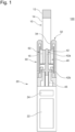
- FIG. 1 is a schematic lateral section of a heating system according to the present embodiment.
- a heating system 100 includes a consumable 10 and a heating device 20.
- the heating device 20 is preferably a portable device or a handheld device.
- the consumable 10 includes a smokable material 16 to be heated by the heating device 20, a hollow filter 14, and a filter part 12.
- the heating device 20 includes a battery 22, a printed circuit board (PCB) 24, a housing 30, and a heating unit 40.
- PCB printed circuit board
- the heating device 20 is configured to heat the solid smokable material 16 and atomize the smokable material 16.
- the smokable material 16 forms a part of the consumable 10 having a pillar shape extending in the longitudinal direction, for example.
- the consumable 10 may be a tobacco stick in which the smokable material 16 contains tobacco, for example.
- the battery 22 stores power to be used by the heating device 20.
- the battery 22 is a lithium-ion battery.
- the battery 22 may also be chargeable by an external power source.
- the PCB 24 includes a CPU, a memory, and the like, and controls operations by the heating device 20. For example, the PCB 24 starts the heating of the smokable material 16 in response to a user operation performed on an input device such as a push-button or a sliding switch not illustrated, and ends the heating of the smokable material 16 after a certain time has passed.
- the PCB 24 may also end the heating of the smokable material 16 if a number of puff operations by the user exceeds a certain value, even if the certain time has not yet passed since the start of the heating of the smokable material 16. For example, puff operations are detected by a sensor not illustrated.
- the PCB 24 may start the heating of the smokable material 16 in response to the start of a puff operation, and end the heating of the smokable material 16 in response to the end of a puff operation.
- the PCB 24 may also end the heating of the smokable material 16 if a certain time has passed since the start of the puff operation, even if the puff operation has not yet ended.
- the PCB 24 is disposed between the battery 22 and the heating unit 40.
- the heating device 20 is configured to receive a consumable 10 in stick form.
- the battery 22, the PCB 24, and the heating unit 40 may be arranged in the direction in which the consumable 10 is inserted into the heating device 20.
- the housing 30 is a case that accommodates the battery 22, the PCB 24, and the heating unit 40.
- the housing 30 includes an air inlet 30a for supplying air to the heating unit 40 and an insertion end 32 in which an opening 34 is formed, the consumable 10 being inserted into the opening 34.
- the heating unit 40 includes a heater 42 and a chamber 50.
- the heater 42 has a shape that can be inserted into the smokable material 16, and is configured to heat the smokable material 16 from inside.
- the heater 42 includes a blade 42a (corresponding to one example of the heating element) to be inserted into the smokable material 16 and a holder 42b for securing the heater 42 to the housing 30.
- the blade 42a (heating element) is a portion that contacts the smokable material 16 in a state with the consumable 10 positioned at the desired position inside the chamber 50.
- the blade 42a may include a resin substrate and a heating track formed on the surface of the resin substrate, for example.
- a lead wire 43 for supplying power from the battery 22 to the blade 42a is connected to the blade 42a.
- the heater 42 may also include a susceptor (corresponding to one example of the heating element) that is inductively heated by an induction coil.
- the susceptor is inserted into the smokable material 16 and inductively heated by the induction coil not illustrated, thereby causing the smokable material 16 to be heated.
- FIG. 2 is an enlarged schematic view of the heating unit 40 illustrated in Fig. 1 .
- the chamber 50 includes a side wall 52 surrounding the smokable material 16 and a bottom wall 54 abutted by the end of the smokable material 16.
- the bottom wall 54 has an opening 54a for supplying air to the end of the smokable material 16.
- the heating device 20 is provided with a first gap S1 between the inner circumferential surface of the side wall 52 of the chamber 50 and the smokable material 16 of the consumable 10 accommodated in the chamber 50.
- a first gap S1 By providing the first gap S1, an air insulation layer is formed around the smokable material 16 and the transfer of heat emitted from the blade 42a of the heater 42 to the chamber 50 and the housing 30 through the first gap S1 can be suppressed or reduced, thereby reducing a temperature rise on the surface of the housing 30 and also reducing a loss of heat from the smokable material 16 due to the chamber 50.
- the loss of heat from the outer circumference of the smokable material 16 can be reduced, and therefore an aerosol can be generated more fully from the smokable material 16 even in the latter half of a smoking action.
- the heating device 20 is also provided with a second gap S2 between the housing 30 and the outer circumferential surface of the side wall 52 of the chamber 50.
- the thickness A of the first gap S1 is greater than the thickness B of the second gap S2.
- the volume of the first gap S1 may be greater than the volume of the second gap S2. Since the heating device 20 has the first gap S1 and the second gap S2 and the thickness A of the first gap S1 closest to the blade 42a is relatively large, a convection current of air inside the gap can be limited or reduced compared to the case of a single gap.
- the transfer of heat from the blade 42a and the heated smokable material 16 through the first gap S1 to the chamber 50 and the housing 30 can be suppressed or reduced, and therefore a temperature rise at the surface of the housing 30 can be reduced and a loss of heat from the smokable material 16 due to the chamber 50 can be reduced.
- the loss of heat from the outer circumference of the smokable material 16 can be reduced, and therefore an aerosol can be generated more fully from the smokable material 16 even in the latter half of a smoking action.
- the transfer of heat to the chamber 50 can also be suppressed or reduced, the transfer of heat to the inside of the heating device 20 through the chamber 50 can also be reduced.
- the first gap S1 and the second gap S2 are connected by a third gap S3 that wraps around the end of the side wall 52 of the chamber 50.
- the heating device 20 has an air channel for supplying air to the inside of the chamber 50 from the air inlet 30a of the housing 30.
- the heating device 20 has a first air channel F1 passing through the second gap S2 and the first gap S1.
- F1 passing through the second gap S2 and the first gap S1.
- holes or notches can be formed in a member (for example, the wrap paper) forming the lateral surface of the consumable 10, or the member forming the lateral surface of the consumable 10 can be configured as a gas-permeable member, for example.
- the air that is supplied to the first gap S1 through the first air channel F1 when the user inhales the consumable 10 can be drawn inside the consumable 10 from the lateral surface of the consumable 10.
- the bottom wall 54 of the chamber 50 may also have a recessed part or a raised part for supporting a part of the consumable 10 such that at least a part of the end surface of the consumable 10 is exposed to the inside of the chamber 50. In this case, when the user inhales the consumable 10, air supplied to the first gap S1 can be drawn inside the consumable 10 from the end surface of the consumable 10.
- the thickness A of the first gap S1 is greater than the thickness B of the second gap S2, the flow rate of the air reaching the first gap S1 is relatively low, and a cooling of the chamber 50 due to a convection current of air can be suppressed or reduced. With this arrangement, the loss of heat from the outer circumference of the smokable material 16 can be reduced.
- the first air channel F1 passes through the second gap S2, the third gap S3, and the first gap S1.
- the heating device 20 further includes a second air channel F2 leading to the opening 54a in the bottom wall 54 of the chamber 50, and a junction F3 that divides the air inlet 30a into the first air channel F1 and the second air channel F2.
- the ratio of the amount of air drawn into the consumable 10 from the lateral surface of the smokable material 16 and the amount of air drawn in from the end surface of the smokable material 16 can be adjusted easily. With this arrangement, the degree of freedom in supplying air to the consumable 10 can be improved. Note that in the case where the air supplied to the first gap S1 can be drawn inside the consumable 10 from the first air channel F1 as described above, the bottom wall 54 of the chamber 50 need not have the opening 54a.
- the insertion end 32, the bottom wall 54, the junction F3, and the air inlet 30a are disposed in the above order in the insertion direction of the consumable 10.
- the second air channel F2 can be easily made shorter in length than the first air channel F1, and the proportional amount of air to be supplied to the end of the smokable material 16 from the second air channel F2 can be increased easily.
- the second air channel F2 since the second air channel F2 has a channel length that is shorter than the first air channel F1 and a channel cross-sectional area that is larger than the first air channel F1, the amount of air supplied to the smokable material 16 from the second air channel F2 is greater than the amount of air supplied to the smokable material 16 from the first air channel F1.
- air can be supplied to the smokable material 16 efficiently while a cooling of the chamber 50 due to a convection current of air in the second air channel F2 is suppressed or reduced.
- the chamber 50 has a contacting part 56 that contacts the housing 30 on the battery 22 side in the insertion direction of the consumable 10.
- the contacting part 56 is secured to the housing 30, thereby securing the chamber 50 to the housing 30.
- the contacting part 56 may be a cylindrical, rod-like, or other member extending from the side wall 52 or the bottom wall 54 of the chamber 50, for example.
- the contacting part 56 is disposed at a position that does not overlap with the blade 42a of the heater 42 in the insertion direction of the consumable 10.
- the contacting part 56 is disposed farther on the battery 22 side (the opposite side from the insertion end 32 of the housing 30) than the blade 42a of the heater 42 in the insertion direction of the consumable 10.
- one end (the end on the insertion end 32 side) of the chamber 50 is preferably located farther on the insertion end 32 side of the housing 30 than the blade 42a of the heater 42 in the insertion direction of the consumable 10.
- the first gap S1 and the second gap S2 are demarcated by the side wall 52 of the chamber 50, and therefore a convection current of air between the first gap S1 and the second gap S2 can be suppressed or reduced, and the transfer of heat from the first gap S1 to the second gap S2 can be suppressed or reduced.
- the housing 30 includes a guide 36, the guide 36 demarcating the opening 34 into which the consumable 10 is inserted.
- the guide 36 is a cylindrical member of which the rim forming the opening 34 extends toward the battery 22 side.
- the guide 36 has an inner surface 36a that contacts the outer circumferential surface of the consumable 10 inserted into the heating device 20 through the opening 34 and guides the smokable material 16 to the heater 42. In the state illustrated in Fig.
- the smokable material 16 is positioned by the bottom wall 54 (corresponding to one example of the positioning part) such that the guide 36 does not contact the lateral surface of the consumable 10 corresponding to the location of the smokable material 16 in the insertion direction of the consumable 10.
- the length of the guide 36 is designed such that the guide 36 does not contact the smokable material 16 when the smokable material 16 is to be heated by the heating device 20.
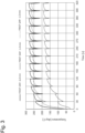
- the temperature of the outermost layer of the smokable material 16 was measured with the thickness A of the first gap S1 of the heating device 20 illustrated in Figs. 1 and 2 set to 1.0 mm, 1.5 mm, and 2.0 mm, respectively.
- the blade 42a of the heater 42 is controlled to rise to 350°C after the start of heating and remain at 350°C upon reaching 350°C.
- the state of a user using the heating device 20 was simulated by applying suction of predetermined magnitude every 30 seconds after the blade 42a of the heater 42 starts heating.
- the consumable 10, containing a paper-wrapped tobacco sheet as one example of the smokable material 16, has a diameter of 7.0 mm, and the blade 42a is pin-shaped with a length of 12.0 mm and a diameter of 2.5 mm.
- the blade 42a forms a pin heater.
- the pin heater includes a conducting track inside a ceramic, and the temperature of the pin heater itself rises due to resistance heating. Note that the temperature of the heater 42 is the value obtained by measuring the highest temperature on the outer surface of the pin heater.
- Fig. 3 is a graph illustrating the temperature of the outermost layer of a smokable material 16.
- the vertical axis represents temperature and the horizontal axis represents time.
- the temperature rises gradually after heating is started, and the temperature begins to stabilize at a time point around 150 seconds. From the time point roughly around 270 seconds, the temperature falls temporarily due to the suction applied every 30 seconds, with the temperature varying from 150°C to 200°C.
- the temperature rises gradually after heating is started, and the temperature begins to stabilize at a time point around 90 seconds. From the time point at 120 seconds, the temperature varies from roughly 210°C to roughly 260°C. Likewise, in the case where the thickness A of the first gap S1 is 2.0 mm, the temperature rises gradually after heating is started, and the temperature begins to stabilize at a time point around 90 seconds. From the time point at 120 seconds, the temperature varies from roughly 200°C to roughly 275°C.
- the temperature of the outermost layer of the smokable material 16 does not reach 200°C.
- the temperature at which an aerosol source such as glycerin or propylene glycol included in the smokable material 16 evaporates is approximately 250°C, for example. Consequently, the above demonstrates that in the case where the thickness A of the first gap S1 is 1.0 mm, heat in the smokable material 16 is lost to the chamber 50, and the temperature of the outer circumferential surface of the consumable 10 does not rise to the evaporation temperature of the aerosol source.
- the temperature of the outermost layer of the smokable material 16 exceeds 250°C.
- the above demonstrates that in the cases where the thickness A of the first gap S1 is 1.5 mm and 2.0 mm, the loss of heat from the smokable material 16 to the chamber 50 is suppressed or reduced, and the aerosol source is evaporated even from the outermost layer of the smokable material 16.
- the aerosol source can be evaporated from substantially the entire smokable material 16 and the generated quantity of aerosol can be increased compared to the case where the thickness A is 1.0 mm.
- the graph in Fig. 3 also demonstrates that the temperature difference between the cases where the thickness A of the first gap S1 is 1.0 mm and 1.5 mm is clearly large compared to the temperature difference between the cases where the thickness A of the first gap S1 is 1.5 mm and 2.0 mm.
- the difference in the thickness A of the first gap S1 is the same 0.5 mm
- decreasing the thickness A from 1.5 mm to 1.0 mm results in greatly lowered heat insulation performance
- increasing the thickness A from 1.5 mm to 2.0 mm does not result in a large change to the heat insulation performance of the first gap S1.
- the heat insulation performance can be said to deteriorate markedly at a critical point around a thickness A of 1.5 mm for the first gap S1.
- the thickness A of the first gap S1 is set to less than 1.5 mm, the deterioration in the heat insulation performance per unit thickness is striking compared to the case where the thickness A is 1.5 mm or greater.
- the thickness A of the first gap S1 is preferably equal to or greater than 1.5 mm. Also, if the thickness A of the first gap S1 is significantly larger than 1.5 mm, the outermost layer of the smokable material 16 can be heated sufficiently, but the heating device 20 (housing 30) is enlarged unnecessarily. A trend was also observed in which an increase in the thickness A resulted in a lower temperature during the suction applied every 30 seconds. For these reasons, from the perspective of the size of the heating device 20 and the temperature drop during inhalation, the thickness A of the first gap S1 is preferably less than or equal to 3.0 mm. In addition, referring to the graph in Fig.
- the thickness A of the first gap S1 is more preferably less than or equal to 2.0 mm.
- the inner surface 36a of the guide 36 demarcates the opening 34 into which the consumable 10 is inserted. Since the inner surface 36a of the guide 36 contacts the outer circumferential surface of the consumable 10 when the consumable 10 is inserted into the opening 34, the diameter of the inner surface 36a of the guide 36 can be considered to be substantially equal to the outer diameter of the consumable 10. For this reason, the distance between the inner surface of the side wall 52 of the chamber 50 and the inner surface 36a of the guide 36 in the direction orthogonal to the insertion direction of the consumable 10 is substantially equal to the size of the thickness A of the first gap S1.
- the distance between the inner surface of the side wall 52 of the chamber 50 and the inner surface 36a of the guide 36 in the direction orthogonal to the insertion direction of the consumable 10 can be considered to be preferably equal to or greater than 1.5 mm and less than or equal to 3.0 mm, more preferably equal to or greater than 1.5 mm and less than or equal to 2.0 mm.
- FIG. 4 is an enlarged schematic view of the heating unit 40 of the heating device 20 according to another embodiment.
- the heating device 20 illustrated in Fig. 4 differs in that the chamber 50 is configured to be movable with respect to the housing 30 in the insertion direction of the consumable 10.
- the contacting part 56 of the chamber 50 is not secured to the housing 30, but is configured to be slidable with respect to the housing 30.
- the housing 30 has an opening 30b, and a portion of a lever 58 coupled to the contacting part 56 is exposed to the outside of the housing 30 through the opening 30b.
- the opening 30b is connected to the first air channel F1 and the second air channel F2 and may also function as an air inlet.
- the user by moving the lever 58 in the insertion direction of the consumable 10, can move the chamber 50 to which the lever 58 is coupled in the insertion direction of the consumable 10.
- the smokable material 16 can be removed from the blade 42a while the spilling out of the smokable material 16 such as cut tobacco from the consumable 10 is suppressed or reduced.
- a portion of the third gap S3 serves as the range of motion of the side wall 52 of the chamber 50 when the chamber 50 is moved toward the insertion end 32.
- the first gap S1 and the second gap S2 are connected through the third gap S3 by the side wall 52 of the chamber 50.
- the third gap S3 is not sealed off by the side wall 52 of the chamber 50.
- the lever 58 may be connected to any part of the chamber 50, but is preferably connected to the contacting part 56. As described above, since the contacting part 56 is provided at a position relatively apart from the blade 42a, the transfer of heat from the blade 42a to the contacting part 56 is suppressed or reduced. For this reason, by connecting the lever 58 to the contacting part 56, heat from the blade 42a is transferred less readily to the lever 58, and the user can operate the lever 58 more safely.
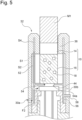
- Fig. 5 is an enlarged schematic view of the heating unit 40 of the heating device 20 according to yet another embodiment.
- the heating device 20 illustrated in Fig. 5 differs in that the first gap S1 and the second gap S2 are not connected and in that an induction coil 44 and susceptors 18 (corresponding to one example of the heating element) are provided instead of the heater 42.
- the susceptors 18 are provided inside the smokable material 16 of the consumable 10.
- a mouthpiece M1 is provided in the guide 36 instead of the filter part 12.
- the heating device 20 is provided with a gap S4 for sliding of substantially equal thickness to the thickness of the side wall 52 of the chamber 50, instead of the third gap S3.
- the gap S4 for sliding extends in the insertion direction of the consumable 10.
- the leading end of the side wall 52 of the chamber 50 is inserted substantially without a gap into a portion of the gap S4 for sliding, and a portion of the gap S4 for sliding serves as the range of motion of the side wall 52 of the chamber 50 when the chamber 50 is moved toward the insertion end 32.
- the first gap S1 and the second gap S2 are demarcated by the side wall 52 of the chamber 50, and are not connected to one another. Consequently, a convection current of air between the first gap S 1 and the second gap S2 can be blocked, and therefore the heat insulation performance in the first gap S1 and the second gap S2 can be improved further.
- the second gap S2 may or may not be connected to the air inlet 30a.
- the gap S4 for sliding may also have air holes connected to the outside of the housing 30 for allowing air to escape when the chamber 50 is moved toward the insertion end 32.
- the hollow filter 14 of the consumable 10 preferably is formed from a material with low thermal conductivity. By disposing the hollow filter 14 inside the opening 34 in the housing 30, the hollow filter 14 and the smokable material 16 may be positioned in the direction orthogonal to the insertion direction of the consumable 10.
- the hollow filter 14 is not limited to a hollow structure, and may also be a member having any structure that allows an aerosol to pass through.
- the mouthpiece M1 may be removably attached to the consumable 10.
- the mouthpiece M1 may be used repeatedly with a plurality of consumables 10. After the mouthpiece M1 is removed, the consumable 10 may be stuck inside the heating device 20 and difficult to retrieve. Accordingly, the user can operate the lever 58 to move the chamber 50 toward the insertion end 32, and thereby push out the end of the consumable 10 from the heating device 20.
- the induction coil 44 may be a flat coil having a spiral shape, for example. As illustrated in Fig. 5 , in the state with the consumable 10 positioned at the desired position inside the chamber 50, the induction coil 44 may be provided on the opposite side of the consumable 10 with the bottom wall 54 of the chamber 50 in between.
- the induction coil 44 is configured to inductively heat the susceptors 18 provided inside the smokable material 16, thereby causing the susceptors 18 to generate heat. With this arrangement, the heat-generating susceptors 18 can heat the smokable material 16 from inside.
- the housing 30 and/or the chamber 50 preferably are magnetically permeable and non-conducting (electrically insulating).
- the housing 30 and/or the chamber 50 do not generate heat readily in response to the induction coil 44, and the susceptors 18 can be made to generate heat efficiently.
- magnetically permeable and non-conducting (electrically insulating) materials include glass, plant matter, wood, paper, and resins such as PEEK.
Abstract
Description
- The present invention relates to a heating device and a heating system.
- In the related art, a flavor inhaler for inhaling flavors and the like without combusting a material is known. As an example of such a flavor inhaler, an electrically heated aerosol-generating system provided with a cavity accommodating a smoking article inside a housing is known (PTL 1). In the electrically heated aerosol-generating system, an internal air flow channel is provided between the housing and the cavity, and by causing air to pass through the internal air flow channel and be supplied to the smoking article, the air can be preheated.
PTL 1 also indicates that by providing the internal air flow channel, the housing is cooled. - PTL 1:
Japanese Patent No. 5963375 - One objective of the present invention is to provide a heating device and a heating system having a novel structure.
- According to a first aspect of the present invention, a heating device that can heat a smokable material included in a consumable is provided. The heating device includes: an air inlet; a housing; a heating element that heats the smokable material from inside; a chamber which is located inside the housing and which has a side wall surrounding a lateral surface of the smokable material; a first gap of which at least a portion is demarcated by an inner circumferential surface of the side wall of the chamber and a lateral surface of the consumable accommodated in the chamber; and a second gap between the housing and an outer circumferential surface of the side wall of the chamber. The thickness of the first gap is greater than the thickness of the second gap.
- According to the first aspect above, since a plurality of gaps are included and the thickness of the first gap closest to the heating element is relatively large, a convection current of air inside the gap can be limited or reduced compared to the case of a single gap, and at least one of the following may be achieved. The transfer of heat from the heating element and the heated smokable material through the first gap to the chamber and the housing can be suppressed or reduced, and therefore a temperature rise at the surface of the housing can be reduced and a loss of heat from the smokable material due to the chamber can be reduced. In particular, the loss of heat from the outer circumference of the smokable material can be reduced, and therefore an aerosol can be generated more fully from the smokable material even in the latter half of a smoking action. Moreover, since the transfer of heat to the chamber can also be suppressed or reduced, the transfer of heat to the inside of the heating device through the chamber can also be reduced. Note that a reduction of heat transfer to the inside of the heating device is preferable from the perspective of device protection.
- In this specification, the "first gap" refers to a space in which, in the state with the consumable positioned at a desired position inside the chamber, at least a portion of the gap is demarcated by the inner circumferential surface of the side wall of the chamber located in a location corresponding to the length of the smokable material inside the chamber in the insertion direction of the smokable material and the lateral surface of the consumable accommodated in the chamber. The thickness of the first gap refers to "the distance, in the first gap, in a direction extending in the radial direction from an axis which passes through the center of the chamber and which extends in the longitudinal direction of the heating device (the insertion direction of the consumable)". Specifically, the thickness of the first gap may also be thought of as "the longest distance, in the first gap, among the distances in the direction extending in the radial direction from an axis which passes through the center of the chamber and which extends in the longitudinal direction of the heating device", or as "the shortest distance, in the first gap, among the distances in the direction extending in the radial direction from an axis which passes through the center of the chamber and which extends in the longitudinal direction of the heating device". Similarly, the "second gap" refers to a space that exists in the state with the consumable positioned at the desired position inside the chamber, the gap existing between the housing located in a location corresponding to the length of the smokable material inside the chamber in the insertion direction of the smokable material and the outer circumferential surface of the side wall of the chamber. The thickness of the second gap refers to "the distance, in the second gap, in a direction extending in the radial direction from an axis which passes through the center of the chamber and which extends in the longitudinal direction of the heating device". Specifically, the thickness of the second gap may also be thought of as "the longest distance, in the second gap, among the distances in the direction extending in the radial direction from an axis which passes through the center of the chamber and which extends in the longitudinal direction of the heating device", or as "the shortest distance, in the second gap, among the distances in the direction extending in the radial direction from an axis which passes through the center of the chamber and which extends in the longitudinal direction of the heating device". In other words, the "first gap" and the "second gap" are gaps located on the outer radial side of the smokable material accommodated in the chamber, in the insertion direction of the smokable material. Also, in this specification, the "state with the consumable positioned at the desired position inside the chamber" refers to a state in which the consumable is positioned correctly at the intended position inside the chamber for generating an aerosol from the consumable (for example, in the case where the chamber has "a bottom wall abutted by the inserted consumable", the state in which the consumable abuts at least a part of the bottom, or in the case where the heating device includes an "abutting part abutted by the inserted consumable" on the inside or the outside of the chamber, the state in which the consumable abuts at least a part of the abutting part").
- The heating element is shaped like a pin, a blade, or the like that can be inserted into the smokable material. For example, the heating element may include a support such as a base plate or core of ceramic, heat-resistant resin, or the like that is resistant to heating and rigid enough to allow insertion into the smokable material, and a heat generator such as a resistively heatable heating track formed on the surface or the inside of the support. The heating element is not limited to the above and may also be a susceptor that is inductively heated by an induction coil. The term "susceptor" in this specification means a material that can convert electromagnetic energy into heat, and refers to a material for the purpose of heating the "smokable material". The susceptor is disposed at a position where heat can be transferred to the "smokable material". When the susceptor is located inside a fluctuating electromagnetic field, eddy currents induced in the susceptor and magnetic hysteresis loss inside the susceptor cause the susceptor to heat up. The heating element may also be a portion that contacts the smokable material in a state with the consumable positioned at the desired position inside the chamber.
- The susceptor preferably includes a material selected from at least one of the group consisting of aluminum, iron, nickel, and alloys thereof (for example, nichrome and stainless steel). The susceptor may have any shape, and may be granular, rod-like, strip-shaped, tubular, or cylindrical, for example. If the shape of the susceptor is tubular with looping electrical paths, eddy currents can be generated efficiently. A plurality of susceptors having the same shape or a plurality of susceptors having different shapes may be arranged in a compartment.
- In the case where a susceptor is adopted as the heating element, the housing and/or the chamber preferably are magnetically permeable and non-conducting (electrically insulating). With this configuration, the housing and/or the chamber do not generate heat readily in response to the induction coil, and the susceptor can be made to generate heat efficiently. Examples of magnetically permeable and non-conducting (electrically insulating) materials include glass, plant matter, wood, paper, and resins such as PEEK.
- The induction coil may be a flat coil or a cylindrical coil, for example. In the state with the consumable positioned at the desired position inside the chamber, the induction coil may be provided on the opposite side of the consumable with the bottom wall of the chamber in between, or may be provided to surround the chamber.
- The heating device may have an air channel from the air inlet to the inside of the chamber, and the air channel may include a first air channel passing through the second gap and the first gap. With this arrangement, air reaches the first gap through the second gap, and therefore air can be supplied to the smokable material from the first gap. In this case, by forming holes or notches in a member (for example, the wrap paper) forming the lateral surface of the consumable, or by configuring the member forming the lateral surface of the consumable to be a gas-permeable member, for example, the air that is supplied to the first gap when a user inhales the consumable can be drawn inside the consumable from the lateral surface of the consumable. The chamber may also have a bottom abutted by the consumable inserted into the chamber. The bottom may also have a recessed part or a raised part for supporting a part of the consumable positioned at the desired position in the chamber such that at least a part of the end surface of the consumable is exposed to the inside of the chamber. In this case, when the user inhales the consumable, air supplied to the first gap through the second gap can be drawn inside the consumable from the end surface of the consumable. Also, since the thickness of the first gap is greater than the thickness of the second gap, the flow rate of the air reaching the first gap is relatively low, and a cooling of the chamber due to a convection current of air can be suppressed or reduced. With this arrangement, the loss of heat from the outer circumference of the smokable material can be reduced.
- In the heating device, the first gap and the second gap may also be configured not to be connected with each other in the state with the consumable positioned at the desired position inside the chamber. With this arrangement, a convection current of air between the first gap and the second gap can be blocked, and therefore the heat insulation performance in the first gap and the second gap can be improved further.
- The chamber may have a bottom wall with an opening. The air channel may include a second air channel leading to the opening in the bottom wall of the chamber. With this arrangement, in the case where the first air channel passing through the second gap and the first gap is included, air can be supplied from the opening in the bottom wall of the chamber to the end of the smokable material in addition to the supply of air from the first gap to the smokable material, and therefore air flow ratio of the first air channel and the second air channel can be adjusted easily. In other words, for example, the ratio of the amount of air drawn into the consumable from the lateral surface of the smokable material and the amount of air drawn in from the end surface of the smokable material can be adjusted easily. With this arrangement, the degree of freedom in supplying air to the consumable can be improved.
- The housing may have an insertion end into which the consumable is inserted, the heating device may include a junction that divides the air inlet into the first air channel and the second air channel, and the insertion end, the bottom wall, the junction, and the air inlet may be disposed in the above order in the insertion direction of the consumable. With this arrangement, the second air channel can be easily made shorter in length than the first air channel, and the proportional amount of air to be supplied to the end of the smokable material from the second air channel can be increased easily. As a result, air can be supplied to the smokable material efficiently while a cooling of the chamber due to a convection current of air in the first gap is suppressed or reduced.
- The amount of air supplied to the smokable material from the second air channel may be greater than the amount of air supplied to the smokable material from the first air channel when the user inhales the consumable. With this arrangement, an aerosol can be released from the smokable material efficiently while a cooling of the chamber due to a convection current of air in the first air channel is suppressed or reduced.
- The heating device may include a positioning part that positions the smokable material at a position in the insertion direction of the consumable such that a part of the heating device does not contact the lateral surface of the consumable corresponding to the smokable material when the smokable material is to be heated. With this arrangement, a release of heat from the heated smokable material through a part of the heating device may be suppressed or reduced.
- The heating device may also include a guide that contacts the consumable and guides the smokable material to the heating element. A part of the heating device may also be the guide. With this arrangement, a release of heat from the heated smokable material through the guide may be suppressed or reduced in the case where the smokable material is positioned by the positioning part at a position in the insertion direction of the consumable such that the guide does not contact the lateral surface of the consumable corresponding to the smokable material.
- The volume of the first gap is preferably larger than the volume of the second gap. The chamber may also have a contacting part that contacts the housing. The contacting part is preferably disposed at a position that does not overlap with the heating element in the insertion direction of the consumable. With this arrangement, since the heating element is provided at a position apart from the contacting part of the chamber, the transfer of heat from the heating element to the housing and the inside of the device through the contacting part is suppressed or reduced. As a result, the smokable material can be heated efficiently, and a temperature rise of the housing and the inside of the device can be suppressed or reduced. In the insertion direction of the consumable, one end of the side wall of the chamber is preferably located farther toward the insertion end of the housing than the heating element. With this arrangement, the first gap and the second gap are demarcated by the side wall of the chamber, and therefore a convection current of air between the first gap and the second gap can be suppressed or reduced, and the transfer of heat from the first gap to the second gap can be suppressed or reduced.
- The bottom wall of the chamber may be configured to be movable with respect to the housing in the insertion direction of the consumable. With this arrangement, after the consumable has been used, by causing the chamber to move away from the heating element (that is, toward the insertion end of the housing) with the smokable material placed inside the chamber, the smokable material can be removed from the heating element easily while the spilling out of the smokable material such as cut tobacco from the consumable is suppressed or reduced. Otherwise, the consumable can be removed from the housing easily after the consumable has been used.
- The heating device may also have an operating part such as a lever which is coupled to the chamber and of which a part is exposed to the outside of the housing. With this arrangement, the user can operate the operating part to move the bottom wall of the chamber with respect to the housing in the insertion direction of the consumable. The operating part is preferably connected to the contacting part of the chamber. With this arrangement, in the case where the contacting part is provided at a position relatively apart from the heating element, the transfer of heat from the heating element to the contracting part is suppressed or reduced. For this reason, by connecting the operating part to the contacting part, heat from the heating element is transferred less readily to the operating part, and the user can operate the operating part more safely.
- The smokable material may be wrapped by a first wrap paper that is permeable to air. The first wrap paper may be provided with a lid that is permeable to air and prevents the smokable material from falling out. The lid may be affixed to the first wrap paper with glue or secured to the first wrap paper by friction. The lid may be a paper filter or an acetate filter, for example. The consumable may also include a cylindrical member. The cylindrical member may be a paper tube or a hollow filter.
- The hollow filter may be formed from a packing layer including one or multiple hollow channels and a plug wrapper covering the packing layer. The fibers in the packing layer have a high packing density, and therefore during inhalation, the air and the aerosol only flow through the hollow channels, and there is little or no flow inside the packing layer. The hollow filter may also include a mouthpiece formed from an adjacent filter part or the like.
- The length of the smokable material in the longitudinal direction is preferably 40 mm to 90 mm, more preferably 50 mm to 75 mm, even more preferably 50 mm to 60 mm. The circumference of the smokable material is preferably 15 mm to 25 mm, more preferably 17 mm to 24 mm, even more preferably 20 mm to 23 mm. Also, the length of the smokable material may be from 12 mm to 22 mm, the length of the first wrap paper may be from 12 mm to 22 mm, the length of the hollow filter may be from 7 mm to 26 mm, and the length of the filter part may be from 6 mm to 20 mm.
- The smokable material included in the consumable may contain an aerosol source that generates an aerosol when heated to a predetermined temperature. The type of the aerosol source is not particularly limited, and extracts and/or their components from any of various types of natural substances may be selected according to the purpose. Examples of the aerosol source include glycerin, propylene glycol, triacetin, 1,3-butanediol, and mixtures thereof. The quantity of aerosol source in a solid smokable material (percent by weight with respect to the overall weight of the smokable material) is not particularly limited, but from the perspective of generating the aerosol sufficiently and also imparting a pleasant flavor, the quantity is normally equal to or greater than 5% by weight, preferably equal to or greater than 10% by weight, and furthermore, is normally less than or equal to 50% by weight, preferably less than or equal to 20% by weight.
- For the smokable material, tobacco such as the lamina or midrib, or some other known plant material may be used. Additionally, the smokable material such as tobacco may be shaped into cuttings, sheets, strings, a powder, granules, pellets, a slurry, a porous shape, or the like. In the case where the smokable material has a circumference from 20 mm to 23 mm and a length from 18 mm to 22 mm, the quantity range of the smokable material such as tobacco contained in the consumable may be from 200 mg to 400 mg for example, preferably from 250 mg to 320 mg. The moisture content of the smokable material including tobacco or the like as the smokable material (percent by weight with respect to the overall weight of the smokable material) is from 8% by weight to 18% by weight, for example, preferably from 10% by weight to 16% by weight. When such moisture content is present, roll staining is suppressed or reduced and favorable rollability during manufacturing is achieved. The size and preparation method of the cut tobacco used as one example of the smokable material is not particularly limited. For example, dried tobacco leaf that has been cut into pieces having a width from 0.8 mm to 1.2 mm may be used. Also, dried tobacco leaf may be pulverized such that the average particle size is approximately from 20 µm to 200 µm, and then uniform particles thereof may be worked into sheets and cut into pieces having a width from 0.8 mm to 1.2 mm and used. Furthermore, a product obtained by gathering the sheets worked as above without cutting may also be used as the smokable material. Furthermore, the smokable material may also be in a liquid state and the liquid may be viscous. In this case, the aerosol source may occupy the majority of the smokable material. The aerosol source content in the smokable material in liquid form (percent by weight with respect to the overall weight of the smokable material) can be set to 80% by weight or greater, 90% by weight or greater, or 95% by weight or greater. Additionally, the smokable material may also include one or multiple types of aromatic substances. The type of the aromatic substance is not particularly limited, but menthol is preferable from the perspective of imparting a pleasant flavor.
- The consumable may also include a second wrap paper which is different from the first wrap paper and which is used to wrap at least one of the cylindrical member, the hollow filter part, and the filter part. The second wrap paper may also wrap a part of the first wrap paper used to wrap the smokable material. The first wrap paper and the second wrap paper of the consumable can be made from paper stock having a basis weight from 20 gsm to 65 gsm, for example. The thickness of the first wrap paper and the second wrap paper is not particularly limited, but from the perspective of rigidity, air permeability, and ease of adjustment during papermaking, is preferably from 10 µm to 100 µm.
- A loading material may also be included in the first wrap paper and the second wrap paper of the consumable. The loading material content may be from 10% by weight to 60% by weight with respect to the total weight of the first wrap paper and the second wrap paper, preferably from 15% by weight to 45% by weight. For the preferable range of basis weight (25 gsm to 45 gsm), the loading material is preferably from 15% by weight to 45% by weight. Calcium carbonate, titanium dioxide, or kaolin can be used as the loading material, for example. Paper including such a loading material presents a bright white color that is preferable from the perspective of appearance for use as a wrap paper for the consumable, and can retain its whiteness permanently. By including a large amount of such a loading material, the ISO whiteness of the wrap paper can be set equal to or greater than 83%, for example. Also, from a practical perspective of use as a wrap paper for the consumable, the first wrap paper and the second wrap paper preferably have a tensile strength equal to or greater than 8 N / 15 mm. The tensile strength can be raised by reducing the loading material content. Specifically, the tensile strength can be raised by reducing the loading material content below the upper limit on the loading material content indicated in the basis weight ranges indicated as an example above.
- Note that the features of another aspect may be combined with or applied to the first aspect, insofar as the action and effect of the first aspect are not impaired.
- According to a second aspect of the present invention, a heating system is provided. The heating system includes the above heating device and a consumable provided with a smokable material to be heated by the heating device. The consumable may be positioned at a desired position inside the heating device. Here, the "desired position inside the heating device" where the consumable is positioned refers to a position where suitable heating can be performed to generate an aerosol from the smokable material.
- Note that the features of another aspect may be combined with or applied to the second aspect, insofar as the action and effect of the second aspect are not impaired.
- According to a third aspect, a heating system is provided, the heating system including a heating device that can heat a smokable material included in a consumable and a consumable provided with the smokable material to be heated by the heating device. The heating system includes: an air inlet; a housing; a heating element that heats the smokable material from inside; a chamber which is located inside the housing and which has a side wall surrounding a lateral surface of the smokable material; a first gap of which at least a portion is demarcated by an inner circumferential surface of the side wall of the chamber and a lateral surface of a consumable accommodated in the chamber; and a second gap between the housing and an outer circumferential surface of the side wall of the chamber. The thickness of the first gap is greater than the thickness of the second gap.
- According to the third aspect, since a plurality of gaps are included and the thickness of the first gap closest to the heating element is relatively large, a convection current of air inside the gap can be limited or reduced compared to the case of a single gap. With this arrangement, at least one of the following may be achieved. The transfer of heat from the heating element and the heated smokable material through the first gap to the chamber and the housing can be suppressed or reduced, and therefore a temperature rise at the surface of the housing can be reduced and a loss of heat from the smokable material due to the chamber can be reduced. In particular, the loss of heat from the outer circumference of the smokable material can be reduced, and therefore an aerosol can be generated more fully from the smokable material even in the latter half of a smoking action. Moreover, since the transfer of heat to the chamber can also be suppressed or reduced, the transfer of heat to the inside of the heating device through the chamber can also be reduced. Note that a reduction of heat transfer to the inside of the heating device is preferable from the perspective of device protection. Also, according to the second aspect, the heating element may be provided in the heating device or in the consumable. In the case where the heating element is provided in the consumable, a susceptor that heats the smokable material from inside may be provided.
- Note that the features of another aspect may be combined with or applied to the third aspect, insofar as the action and effect of the third aspect are not impaired.
- According to a fourth aspect, a heating device that can heat a smokable material included in a consumable is provided. The heating device includes: a housing; a heating element that heats the smokable material from inside; a chamber which is located inside the housing and which has a side wall surrounding a lateral surface of the smokable material; and a first gap of which at least a portion is demarcated by an inner circumferential surface of the side wall of the chamber and the smokable material accommodated in the chamber. The thickness of the first gap is equal to or greater than 1.5 mm and less than or equal to 3.0 mm. Preferably, the thickness of the first gap is equal to or greater than 1.5 mm and less than or equal to 2.0 mm .
- According to a fourth aspect, by setting the thickness of the first gap equal to or greater than 1.5 mm and less than or equal to 3.0 mm, heat from the smokable material being lost to the chamber during smoking with the heating device can be suppressed or reduced effectively. Specifically, the outermost layer of the smokable material can be heated above the temperature (for example, approximately 250°C) at which an aerosol source such as glycerin or propylene glycol included in the smokable material evaporates. As a result, an aerosol can be generated effectively from substantially the entire smokable material, and therefore the quantity of aerosol generated in the latter half of a smoking action can be increased in particular. If the thickness of the first gap is less than 1.5 mm, the temperature of the outermost layer of the smokable material falls far below the temperature (for example, approximately 250°C) at which the aerosol source evaporates, and the aerosol may not be generated appropriately. Also, if the thickness of the first gap exceeds 3.0 mm, the outermost layer of the smokable material can be heated sufficiently, but the size of the heating device (housing) is increased unnecessarily. If the thickness of the first gap exceeds 2.0 mm, the effect of reducing the loss of heat from the smokable material to the chamber is lessened even if the thickness is increased, and therefore when the size of the heating device is considered, the thickness of the first gap is preferably equal to or greater than 1.5 mm and less than or equal to 2.0 mm. Note that in this specification, the "latter half of a smoking action" refers to the latter half of a smoking action performed with respect to a single consumable.
- Note that the features of another aspect may be combined with or applied to the fourth aspect, insofar as the action and effect of the fourth aspect are not impaired.
- According to a fifth aspect, a heating device that can heat a smokable material included in a consumable is provided. The heating device includes: a housing; a heating element that heats the smokable material from inside; a chamber which is located inside the housing and which has a side wall surrounding a lateral surface of the smokable material; and a guide provided with an inner surface that contacts the consumable and guides the smokable material to the heating element. The distance between the inner surface of the side wall of the chamber and the inner surface of the guide in the direction orthogonal to the insertion direction of the consumable is equal to or greater than 1.5 mm and less than or equal to 3.0 mm. Preferably, the distance between the inner surface of the side wall of the chamber and the inner surface of the guide in the direction orthogonal to the insertion direction of the consumable is equal to or greater than 1.5 mm and less than or equal to 2.0 mm.
- According to the fifth aspect, the distance between the inner surface of the side wall of the chamber and the inner surface of the guide in the direction orthogonal to the insertion direction of the consumable is equal to or greater than 1.5 mm and less than or equal to 3.0 mm. In other words, since the inner surface of the guide contacts the consumable, the distance between the inner surface of the side wall of the chamber and the inner surface of the guide is substantially the same as the distance between the outer surface of the consumable and the inner surface of the side wall of the chamber. Consequently, according to the fifth aspect, in the state with the consumable positioned at a desired position inside the chamber, the thickness of the space between an outer circumferential surface of the smokable material and an inner circumferential surface of the side wall of the chamber is approximately equal to or greater than 1.5 mm and less than or equal to 3.0 mm. With this arrangement, heat from the smokable material being lost to the chamber during smoking with the heating device can be suppressed or reduced effectively. Specifically, the outermost layer of the smokable material can be heated above the temperature (for example, approximately 250°C) at which an aerosol source such as glycerin or propylene glycol included in the smokable material evaporates. As a result, an aerosol can be generated effectively from substantially the entire smokable material, and therefore the quantity of aerosol generated in the latter half of a smoking action can be increased in particular. If the thickness of the space is less than 1.5 mm, the temperature of the outermost layer of the smokable material falls far below the temperature (for example, approximately 250°C) at which the aerosol source evaporates, and the aerosol may not be generated appropriately. Also, if the thickness of the space exceeds 3.0 mm, the outermost layer of the smokable material can be heated sufficiently, but the size of the heating device (housing) is increased unnecessarily. If the thickness of the space exceeds 2.0 mm, the effect of reducing the loss of heat from the smokable material to the chamber is lessened even if the thickness is increased. Therefore, when the size of the heating device is considered, the distance between the inner surface of the side wall of the chamber and the inner surface of the guide in the direction orthogonal to the insertion direction of the consumable, or in other words the thickness of the space, is preferably equal to or greater than 1.5 mm and less than or equal to 2.0 mm.
- Note that the features of another aspect may be combined with or applied to the fifth aspect, insofar as the action and effect of the fifth aspect are not impaired.
-
- [
Fig. 1] Fig. 1 is a schematic lateral section of a heating system according to the present embodiment. - [
Fig. 2] Fig. 2 is an enlarged schematic view of the heating unit illustrated inFig. 1 . - [
Fig. 3] Fig. 3 is a graph illustrating the temperature of the outermost layer of a smokable material. - [
Fig. 4] Fig. 4 is an enlarged schematic view of a heating unit of a heating device according to another embodiment. - [
Fig. 5] Fig. 5 is an enlarged schematic view of a heating unit of a heating device according to yet another embodiment. - Hereinafter, embodiments of the present invention will be described with reference to the drawings. In the drawings described hereinafter, the same or corresponding structural elements are denoted with the same signs, and duplicate description is omitted.
-
Fig. 1 is a schematic lateral section of a heating system according to the present embodiment. Aheating system 100 according to the present embodiment includes a consumable 10 and aheating device 20. Theheating device 20 is preferably a portable device or a handheld device. As illustrated inFig. 1 , the consumable 10 includes asmokable material 16 to be heated by theheating device 20, ahollow filter 14, and afilter part 12. Theheating device 20 includes abattery 22, a printed circuit board (PCB) 24, ahousing 30, and aheating unit 40. - The
heating device 20 is configured to heat the solidsmokable material 16 and atomize thesmokable material 16. Thesmokable material 16 forms a part of the consumable 10 having a pillar shape extending in the longitudinal direction, for example. The consumable 10 may be a tobacco stick in which thesmokable material 16 contains tobacco, for example. Thebattery 22 stores power to be used by theheating device 20. For example, thebattery 22 is a lithium-ion battery. Thebattery 22 may also be chargeable by an external power source. - The
PCB 24 includes a CPU, a memory, and the like, and controls operations by theheating device 20. For example, thePCB 24 starts the heating of thesmokable material 16 in response to a user operation performed on an input device such as a push-button or a sliding switch not illustrated, and ends the heating of thesmokable material 16 after a certain time has passed. ThePCB 24 may also end the heating of thesmokable material 16 if a number of puff operations by the user exceeds a certain value, even if the certain time has not yet passed since the start of the heating of thesmokable material 16. For example, puff operations are detected by a sensor not illustrated. - Alternatively, the
PCB 24 may start the heating of thesmokable material 16 in response to the start of a puff operation, and end the heating of thesmokable material 16 in response to the end of a puff operation. ThePCB 24 may also end the heating of thesmokable material 16 if a certain time has passed since the start of the puff operation, even if the puff operation has not yet ended. In the present embodiment, thePCB 24 is disposed between thebattery 22 and theheating unit 40. - In the example illustrated in the drawings, the
heating device 20 is configured to receive a consumable 10 in stick form. Also, as illustrated in the drawings, thebattery 22, thePCB 24, and theheating unit 40 may be arranged in the direction in which the consumable 10 is inserted into theheating device 20. Thehousing 30 is a case that accommodates thebattery 22, thePCB 24, and theheating unit 40. Thehousing 30 includes anair inlet 30a for supplying air to theheating unit 40 and aninsertion end 32 in which anopening 34 is formed, the consumable 10 being inserted into theopening 34. - The
heating unit 40 includes aheater 42 and achamber 50. Theheater 42 has a shape that can be inserted into thesmokable material 16, and is configured to heat thesmokable material 16 from inside. Specifically, theheater 42 includes ablade 42a (corresponding to one example of the heating element) to be inserted into thesmokable material 16 and aholder 42b for securing theheater 42 to thehousing 30. Theblade 42a (heating element) is a portion that contacts thesmokable material 16 in a state with the consumable 10 positioned at the desired position inside thechamber 50. Theblade 42a may include a resin substrate and a heating track formed on the surface of the resin substrate, for example. Alead wire 43 for supplying power from thebattery 22 to theblade 42a is connected to theblade 42a. Theheater 42 may also include a susceptor (corresponding to one example of the heating element) that is inductively heated by an induction coil. In this case, the susceptor is inserted into thesmokable material 16 and inductively heated by the induction coil not illustrated, thereby causing thesmokable material 16 to be heated. - Next, the
chamber 50 of theheating unit 40 will be described in detail.Fig. 2 is an enlarged schematic view of theheating unit 40 illustrated inFig. 1 . As illustrated inFig. 2 , thechamber 50 includes aside wall 52 surrounding thesmokable material 16 and abottom wall 54 abutted by the end of thesmokable material 16. Thebottom wall 54 has anopening 54a for supplying air to the end of thesmokable material 16. - The
heating device 20 is provided with a first gap S1 between the inner circumferential surface of theside wall 52 of thechamber 50 and thesmokable material 16 of the consumable 10 accommodated in thechamber 50. By providing the first gap S1, an air insulation layer is formed around thesmokable material 16 and the transfer of heat emitted from theblade 42a of theheater 42 to thechamber 50 and thehousing 30 through the first gap S1 can be suppressed or reduced, thereby reducing a temperature rise on the surface of thehousing 30 and also reducing a loss of heat from thesmokable material 16 due to thechamber 50. In particular, the loss of heat from the outer circumference of thesmokable material 16 can be reduced, and therefore an aerosol can be generated more fully from thesmokable material 16 even in the latter half of a smoking action. - The
heating device 20 is also provided with a second gap S2 between thehousing 30 and the outer circumferential surface of theside wall 52 of thechamber 50. In the present embodiment, the thickness A of the first gap S1 is greater than the thickness B of the second gap S2. Preferably, the volume of the first gap S1 may be greater than the volume of the second gap S2. Since theheating device 20 has the first gap S1 and the second gap S2 and the thickness A of the first gap S1 closest to theblade 42a is relatively large, a convection current of air inside the gap can be limited or reduced compared to the case of a single gap. With this arrangement, the transfer of heat from theblade 42a and the heatedsmokable material 16 through the first gap S1 to thechamber 50 and thehousing 30 can be suppressed or reduced, and therefore a temperature rise at the surface of thehousing 30 can be reduced and a loss of heat from thesmokable material 16 due to thechamber 50 can be reduced. In particular, the loss of heat from the outer circumference of thesmokable material 16 can be reduced, and therefore an aerosol can be generated more fully from thesmokable material 16 even in the latter half of a smoking action. Moreover, since the transfer of heat to thechamber 50 can also be suppressed or reduced, the transfer of heat to the inside of theheating device 20 through thechamber 50 can also be reduced. In the example illustrated in the drawings, the first gap S1 and the second gap S2 are connected by a third gap S3 that wraps around the end of theside wall 52 of thechamber 50. - The
heating device 20 has an air channel for supplying air to the inside of thechamber 50 from theair inlet 30a of thehousing 30. Specifically, theheating device 20 has a first air channel F1 passing through the second gap S2 and the first gap S1. With this arrangement, air reaches the first gap S1 through the second gap S2, and therefore air can be supplied to thesmokable material 16 from the first gap S1. In the present embodiment, holes or notches can be formed in a member (for example, the wrap paper) forming the lateral surface of the consumable 10, or the member forming the lateral surface of the consumable 10 can be configured as a gas-permeable member, for example. With this configuration, the air that is supplied to the first gap S1 through the first air channel F1 when the user inhales the consumable 10 can be drawn inside the consumable 10 from the lateral surface of the consumable 10. Also, in the present embodiment, thebottom wall 54 of thechamber 50 may also have a recessed part or a raised part for supporting a part of the consumable 10 such that at least a part of the end surface of the consumable 10 is exposed to the inside of thechamber 50. In this case, when the user inhales the consumable 10, air supplied to the first gap S1 can be drawn inside the consumable 10 from the end surface of the consumable 10. Also, since the thickness A of the first gap S1 is greater than the thickness B of the second gap S2, the flow rate of the air reaching the first gap S1 is relatively low, and a cooling of thechamber 50 due to a convection current of air can be suppressed or reduced. With this arrangement, the loss of heat from the outer circumference of thesmokable material 16 can be reduced. In the example illustrated in the drawings, the first air channel F1 passes through the second gap S2, the third gap S3, and the first gap S1. - The
heating device 20 further includes a second air channel F2 leading to theopening 54a in thebottom wall 54 of thechamber 50, and a junction F3 that divides theair inlet 30a into the first air channel F1 and the second air channel F2. With this arrangement, air can be supplied from theopening 54a in thebottom wall 54 of thechamber 50 to the end of thesmokable material 16 in addition to the supply of air from the first gap S1 to thesmokable material 16, and therefore air flow ratio of the first air channel F1 and the second air channel F2 can be adjusted easily. In other words, for example, the ratio of the amount of air drawn into the consumable 10 from the lateral surface of thesmokable material 16 and the amount of air drawn in from the end surface of thesmokable material 16 can be adjusted easily. With this arrangement, the degree of freedom in supplying air to the consumable 10 can be improved. Note that in the case where the air supplied to the first gap S1 can be drawn inside the consumable 10 from the first air channel F1 as described above, thebottom wall 54 of thechamber 50 need not have theopening 54a. - Regarding the junction F3, as illustrated in the drawings, in the present embodiment, the
insertion end 32, thebottom wall 54, the junction F3, and theair inlet 30a are disposed in the above order in the insertion direction of the consumable 10. With this arrangement, the second air channel F2 can be easily made shorter in length than the first air channel F1, and the proportional amount of air to be supplied to the end of thesmokable material 16 from the second air channel F2 can be increased easily. Consequently, in the present embodiment, since the second air channel F2 has a channel length that is shorter than the first air channel F1 and a channel cross-sectional area that is larger than the first air channel F1, the amount of air supplied to thesmokable material 16 from the second air channel F2 is greater than the amount of air supplied to thesmokable material 16 from the first air channel F1. With this configuration, air can be supplied to thesmokable material 16 efficiently while a cooling of thechamber 50 due to a convection current of air in the second air channel F2 is suppressed or reduced. - As illustrated in
Fig. 2 , thechamber 50 has a contactingpart 56 that contacts thehousing 30 on thebattery 22 side in the insertion direction of the consumable 10. In the present embodiment, the contactingpart 56 is secured to thehousing 30, thereby securing thechamber 50 to thehousing 30. The contactingpart 56 may be a cylindrical, rod-like, or other member extending from theside wall 52 or thebottom wall 54 of thechamber 50, for example. As illustrated in the drawings, the contactingpart 56 is disposed at a position that does not overlap with theblade 42a of theheater 42 in the insertion direction of the consumable 10. Specifically, the contactingpart 56 is disposed farther on thebattery 22 side (the opposite side from theinsertion end 32 of the housing 30) than theblade 42a of theheater 42 in the insertion direction of the consumable 10. With this arrangement, since theblade 42a is provided at a position apart from the contactingpart 56 of thechamber 50, the transfer of heat from theblade 42a to thehousing 30 through the contactingpart 56 is suppressed or reduced. As a result, thesmokable material 16 can be heated efficiently, and a temperature rise of thehousing 30 can be suppressed or reduced. - As illustrated in the drawings, one end (the end on the
insertion end 32 side) of thechamber 50 is preferably located farther on theinsertion end 32 side of thehousing 30 than theblade 42a of theheater 42 in the insertion direction of the consumable 10. With this arrangement, the first gap S1 and the second gap S2 are demarcated by theside wall 52 of thechamber 50, and therefore a convection current of air between the first gap S1 and the second gap S2 can be suppressed or reduced, and the transfer of heat from the first gap S1 to the second gap S2 can be suppressed or reduced. - The
housing 30 includes aguide 36, theguide 36 demarcating theopening 34 into which the consumable 10 is inserted. Theguide 36 is a cylindrical member of which the rim forming theopening 34 extends toward thebattery 22 side. Theguide 36 has an inner surface 36a that contacts the outer circumferential surface of the consumable 10 inserted into theheating device 20 through theopening 34 and guides thesmokable material 16 to theheater 42. In the state illustrated inFig. 2 , that is, when thesmokable material 16 is to be heated by theheating device 20, thesmokable material 16 is positioned by the bottom wall 54 (corresponding to one example of the positioning part) such that theguide 36 does not contact the lateral surface of the consumable 10 corresponding to the location of thesmokable material 16 in the insertion direction of the consumable 10. In other words, the length of theguide 36 is designed such that theguide 36 does not contact thesmokable material 16 when thesmokable material 16 is to be heated by theheating device 20. With this arrangement, a release of heat from the heatedsmokable material 16 through theguide 36 may be suppressed or reduced. - Next, an appropriate numerical value for the thickness A of the first gap S1 in the
heating device 20 described inFigs. 1 and2 will be described. In the present experimental example, the temperature of the outermost layer of thesmokable material 16 was measured with the thickness A of the first gap S1 of theheating device 20 illustrated inFigs. 1 and2 set to 1.0 mm, 1.5 mm, and 2.0 mm, respectively. Theblade 42a of theheater 42 is controlled to rise to 350°C after the start of heating and remain at 350°C upon reaching 350°C. The state of a user using theheating device 20 was simulated by applying suction of predetermined magnitude every 30 seconds after theblade 42a of theheater 42 starts heating. The consumable 10, containing a paper-wrapped tobacco sheet as one example of thesmokable material 16, has a diameter of 7.0 mm, and theblade 42a is pin-shaped with a length of 12.0 mm and a diameter of 2.5 mm. In other words, in the experimental example, theblade 42a forms a pin heater. The pin heater includes a conducting track inside a ceramic, and the temperature of the pin heater itself rises due to resistance heating. Note that the temperature of theheater 42 is the value obtained by measuring the highest temperature on the outer surface of the pin heater. -
Fig. 3 is a graph illustrating the temperature of the outermost layer of asmokable material 16. In the graph illustrated inFig. 3 , the vertical axis represents temperature and the horizontal axis represents time. As illustrated inFig. 3 , in the case where the thickness A of the first gap S1 is 1.0 mm, the temperature rises gradually after heating is started, and the temperature begins to stabilize at a time point around 150 seconds. From the time point roughly around 270 seconds, the temperature falls temporarily due to the suction applied every 30 seconds, with the temperature varying from 150°C to 200°C. On the other hand, in the case where the thickness A of the first gap S1 is 1.5 mm, the temperature rises gradually after heating is started, and the temperature begins to stabilize at a time point around 90 seconds. From the time point at 120 seconds, the temperature varies from roughly 210°C to roughly 260°C. Likewise, in the case where the thickness A of the first gap S1 is 2.0 mm, the temperature rises gradually after heating is started, and the temperature begins to stabilize at a time point around 90 seconds. From the time point at 120 seconds, the temperature varies from roughly 200°C to roughly 275°C. - According to the above experimental example, in the case where the thickness A of the first gap S1 is 1.0 mm, the temperature of the outermost layer of the
smokable material 16 does not reach 200°C. The temperature at which an aerosol source such as glycerin or propylene glycol included in thesmokable material 16 evaporates is approximately 250°C, for example. Consequently, the above demonstrates that in the case where the thickness A of the first gap S1 is 1.0 mm, heat in thesmokable material 16 is lost to thechamber 50, and the temperature of the outer circumferential surface of the consumable 10 does not rise to the evaporation temperature of the aerosol source. On the other hand, in the cases where the thickness A of the first gap S1 is 1.5 mm and 2.0 mm, the temperature of the outermost layer of thesmokable material 16, although falling temporarily due to suction, exceeds 250°C. In other words, the above demonstrates that in the cases where the thickness A of the first gap S1 is 1.5 mm and 2.0 mm, the loss of heat from thesmokable material 16 to thechamber 50 is suppressed or reduced, and the aerosol source is evaporated even from the outermost layer of thesmokable material 16. Consequently, in the cases where the thickness A of the first gap S1 is 1.5 mm and 2.0 mm, the aerosol source can be evaporated from substantially the entiresmokable material 16 and the generated quantity of aerosol can be increased compared to the case where the thickness A is 1.0 mm. - The graph in
Fig. 3 also demonstrates that the temperature difference between the cases where the thickness A of the first gap S1 is 1.0 mm and 1.5 mm is clearly large compared to the temperature difference between the cases where the thickness A of the first gap S1 is 1.5 mm and 2.0 mm. In other words, even though the difference in the thickness A of the first gap S1 is the same 0.5 mm, decreasing the thickness A from 1.5 mm to 1.0 mm results in greatly lowered heat insulation performance, whereas increasing the thickness A from 1.5 mm to 2.0 mm does not result in a large change to the heat insulation performance of the first gap S1. Therefore, if the thickness A of the first gap S1 is decreased little by little, the heat insulation performance can be said to deteriorate markedly at a critical point around a thickness A of 1.5 mm for the first gap S1. In other words, if the thickness A of the first gap S1 is set to less than 1.5 mm, the deterioration in the heat insulation performance per unit thickness is striking compared to the case where the thickness A is 1.5 mm or greater. - Consequently, according to the above experimental example, the thickness A of the first gap S1 is preferably equal to or greater than 1.5 mm. Also, if the thickness A of the first gap S1 is significantly larger than 1.5 mm, the outermost layer of the
smokable material 16 can be heated sufficiently, but the heating device 20 (housing 30) is enlarged unnecessarily. A trend was also observed in which an increase in the thickness A resulted in a lower temperature during the suction applied every 30 seconds. For these reasons, from the perspective of the size of theheating device 20 and the temperature drop during inhalation, the thickness A of the first gap S1 is preferably less than or equal to 3.0 mm. In addition, referring to the graph inFig. 3 , even if the thickness A of the first gap S1 is increased from 1.5 mm to 2.0 mm, no large change occurs in the heat insulation performance of the first gap S1, as described above. Therefore, if the thickness A of the first gap S1 exceeds 2.0 mm, the effect of reducing the loss of heat from thesmokable material 16 to thechamber 50 is thought to be lessened even if the thickness A is increased. For this reason, in consideration of the size and heat insulation performance of theheating device 20, the thickness A of the first gap S1 is more preferably less than or equal to 2.0 mm. - Also, in the
heating device 20 illustrated inFig. 2 , the inner surface 36a of theguide 36 demarcates theopening 34 into which the consumable 10 is inserted. Since the inner surface 36a of theguide 36 contacts the outer circumferential surface of the consumable 10 when the consumable 10 is inserted into theopening 34, the diameter of the inner surface 36a of theguide 36 can be considered to be substantially equal to the outer diameter of the consumable 10. For this reason, the distance between the inner surface of theside wall 52 of thechamber 50 and the inner surface 36a of theguide 36 in the direction orthogonal to the insertion direction of the consumable 10 is substantially equal to the size of the thickness A of the first gap S1. Therefore, according to the above experimental example, the distance between the inner surface of theside wall 52 of thechamber 50 and the inner surface 36a of theguide 36 in the direction orthogonal to the insertion direction of the consumable 10 can be considered to be preferably equal to or greater than 1.5 mm and less than or equal to 3.0 mm, more preferably equal to or greater than 1.5 mm and less than or equal to 2.0 mm. - Next, another embodiment of the
heating device 20 will be described.Fig. 4 is an enlarged schematic view of theheating unit 40 of theheating device 20 according to another embodiment. Compared to theheating device 20 illustrated inFigs. 1 and2 , theheating device 20 illustrated inFig. 4 differs in that thechamber 50 is configured to be movable with respect to thehousing 30 in the insertion direction of the consumable 10. Specifically, the contactingpart 56 of thechamber 50 is not secured to thehousing 30, but is configured to be slidable with respect to thehousing 30. Also, thehousing 30 has anopening 30b, and a portion of alever 58 coupled to the contactingpart 56 is exposed to the outside of thehousing 30 through theopening 30b. As one example, theopening 30b is connected to the first air channel F1 and the second air channel F2 and may also function as an air inlet. The user, by moving thelever 58 in the insertion direction of the consumable 10, can move thechamber 50 to which thelever 58 is coupled in the insertion direction of the consumable 10. - According to the embodiment illustrated in
Fig. 4 , after the consumable 10 has been used, by operating thelever 58 to move thechamber 50 toward theinsertion end 32 with thesmokable material 16 placed inside thechamber 50, thesmokable material 16 can be removed from theblade 42a while the spilling out of thesmokable material 16 such as cut tobacco from the consumable 10 is suppressed or reduced. A portion of the third gap S3 serves as the range of motion of theside wall 52 of thechamber 50 when thechamber 50 is moved toward theinsertion end 32. Even when thechamber 50 is moved toward theinsertion end 32 and thesmokable material 16 is removed from theblade 42a, the first gap S1 and the second gap S2 are connected through the third gap S3 by theside wall 52 of thechamber 50. In other words, the third gap S3 is not sealed off by theside wall 52 of thechamber 50. - Note that the
lever 58 may be connected to any part of thechamber 50, but is preferably connected to the contactingpart 56. As described above, since the contactingpart 56 is provided at a position relatively apart from theblade 42a, the transfer of heat from theblade 42a to the contactingpart 56 is suppressed or reduced. For this reason, by connecting thelever 58 to the contactingpart 56, heat from theblade 42a is transferred less readily to thelever 58, and the user can operate thelever 58 more safely. -
Fig. 5 is an enlarged schematic view of theheating unit 40 of theheating device 20 according to yet another embodiment. Compared to theheating device 20 illustrated inFig. 4 , theheating device 20 illustrated inFig. 5 differs in that the first gap S1 and the second gap S2 are not connected and in that aninduction coil 44 and susceptors 18 (corresponding to one example of the heating element) are provided instead of theheater 42. Thesusceptors 18 are provided inside thesmokable material 16 of the consumable 10. Also, in the consumable 10 illustrated inFig. 5 , unlike the consumable 10 illustrated inFigs. 1 ,2 , and4 , a mouthpiece M1 is provided in theguide 36 instead of thefilter part 12. - Specifically, as illustrated in
Fig. 5 , theheating device 20 is provided with a gap S4 for sliding of substantially equal thickness to the thickness of theside wall 52 of thechamber 50, instead of the third gap S3. The gap S4 for sliding extends in the insertion direction of the consumable 10. As illustrated inFig. 5 , in the state with the consumable 10 positioned at the desired position inside thechamber 50, the leading end of theside wall 52 of thechamber 50 is inserted substantially without a gap into a portion of the gap S4 for sliding, and a portion of the gap S4 for sliding serves as the range of motion of theside wall 52 of thechamber 50 when thechamber 50 is moved toward theinsertion end 32. With this arrangement, the first gap S1 and the second gap S2 are demarcated by theside wall 52 of thechamber 50, and are not connected to one another. Consequently, a convection current of air between thefirst gap S 1 and the second gap S2 can be blocked, and therefore the heat insulation performance in the first gap S1 and the second gap S2 can be improved further. Note that the second gap S2 may or may not be connected to theair inlet 30a. The gap S4 for sliding may also have air holes connected to the outside of thehousing 30 for allowing air to escape when thechamber 50 is moved toward theinsertion end 32. - The
hollow filter 14 of the consumable 10 preferably is formed from a material with low thermal conductivity. By disposing thehollow filter 14 inside theopening 34 in thehousing 30, thehollow filter 14 and thesmokable material 16 may be positioned in the direction orthogonal to the insertion direction of the consumable 10. Thehollow filter 14 is not limited to a hollow structure, and may also be a member having any structure that allows an aerosol to pass through. The mouthpiece M1 may be removably attached to the consumable 10. The mouthpiece M1 may be used repeatedly with a plurality ofconsumables 10. After the mouthpiece M1 is removed, the consumable 10 may be stuck inside theheating device 20 and difficult to retrieve. Accordingly, the user can operate thelever 58 to move thechamber 50 toward theinsertion end 32, and thereby push out the end of the consumable 10 from theheating device 20. - The
induction coil 44 may be a flat coil having a spiral shape, for example. As illustrated inFig. 5 , in the state with the consumable 10 positioned at the desired position inside thechamber 50, theinduction coil 44 may be provided on the opposite side of the consumable 10 with thebottom wall 54 of thechamber 50 in between. Theinduction coil 44 is configured to inductively heat thesusceptors 18 provided inside thesmokable material 16, thereby causing thesusceptors 18 to generate heat. With this arrangement, the heat-generatingsusceptors 18 can heat thesmokable material 16 from inside. In the embodiment inFig. 5 , thehousing 30 and/or the chamber 50 (particularly the bottom wall 54) preferably are magnetically permeable and non-conducting (electrically insulating). With this configuration, thehousing 30 and/or thechamber 50 do not generate heat readily in response to theinduction coil 44, and thesusceptors 18 can be made to generate heat efficiently. Examples of magnetically permeable and non-conducting (electrically insulating) materials include glass, plant matter, wood, paper, and resins such as PEEK. - Although embodiments of the present invention have been described above, the present invention is not limited to the above embodiments, and various modifications are possible within the scope of the technical idea disclosed in the claims, specification, and drawings. Note that any shape or material not described directly in the specification and drawings is still within the scope of the technical idea of the present invention insofar as the actions and effects of the present application are exhibited.
-
- 10:
- consumable
- 16:
- smokable material
- 18:
- susceptor
- 20:
- heating device
- 30:
- housing
- 30a:
- air inlet
- 32:
- insertion end
- 34:
- opening
- 36:
- guide
- 42:
- heating element
- 50:
- chamber
- 52:
- side wall
- 54:
- bottom wall
- 54a:
- opening
- 56:
- contacting part
- 100:
- heating system
- F1:
- first air channel
- F2:
- second air channel
- F3:
- junction
- S1:
- first gap
- S2:
- second gap
Claims (15)
- A heating device that can heat a smokable material included in a consumable, the heating device comprising:an air inlet;a housing;a heating element that heats the smokable material from inside;a chamber which is located inside the housing and which has a side wall surrounding a lateral surface of the smokable material;a first gap of which at least a portion is demarcated by an inner circumferential surface of the side wall of the chamber and a lateral surface of the consumable accommodated in the chamber; anda second gap between the housing and an outer circumferential surface of the side wall of the chamber, whereina thickness of the first gap is greater than a thickness of the second gap.
- The heating device according to claim 1, further comprising:an air channel from the air inlet to an inside of the chamber, whereinthe air channel includes a first air channel passing through the second gap and the first gap.
- The heating device according to claim 1 or 2, further comprising:an air channel from the air inlet to an inside of the chamber, whereinthe chamber has a bottom wall with an opening, andthe air channel includes a second air channel leading to the opening in the bottom wall of the chamber.
- The heating device according to claim 3, whereinthe housing has an insertion end into which the consumable is to be inserted,the heating device includes a junction that divides the air inlet into a first air channel and the second air channel, andthe insertion end, the bottom wall, the junction, and the air inlet are disposed in the above order in an insertion direction of the consumable.
- The heating device according to claim 3 or 4, wherein an amount of air supplied to the smokable material from the second air channel is greater than an amount of air supplied to the smokable material from the first air channel.
- The heating device according to any one of claims 1 to 5, wherein the heating device includes a positioning part that positions the smokable material at a position in an insertion direction of the consumable such that a part of the heating device does not contact the lateral surface of the consumable corresponding to the smokable material when the smokable material is to be heated.
- The heating device according to any one of claims 1 to 6, further comprising a guide that contacts the lateral surface of the consumable and guides the smokable material to the heating element.
- The heating device according to any one of claims 1 to 7, wherein a volume of the first gap is greater than a volume of the second gap.
- The heating device according to any one of claims 1 to 8, whereinthe chamber has a contacting part that contacts the housing, andthe contacting part is disposed at a position that does not overlap with the heating element in an insertion direction of the consumable.
- The heating device according to any one of claims 1 to 9, whereinthe housing has an insertion end into which the consumable is to be inserted, andin an insertion direction of the consumable, one end of the side wall of the chamber is located farther toward the insertion end of the housing than the heating element.
- The heating device according to any one of claims 1 to 10, wherein the bottom wall of the chamber is configured to be movable with respect to the housing in an insertion direction of the consumable.
- A heating system comprising:the heating device according to any one of claims 1 to 10; anda consumable provided with a smokable material to be heated by the heating device.
- A heating system comprising a heating device that can heat a smokable material included in a consumable and a consumable provided with the smokable material to be heated by the heating device, the heating system including:an air inlet;a housing;a heating element that heats the smokable material from inside;a chamber which is located inside the housing and which has a side wall surrounding a lateral surface of the smokable material;a first gap of which at least a portion is demarcated by an inner circumferential surface of the side wall of the chamber and a lateral surface of the consumable accommodated in the chamber; anda second gap between the housing and an outer circumferential surface of the side wall of the chamber, whereina thickness of the first gap is greater than a thickness of the second gap.
- A heating device that can heat a smokable material included in a consumable, the heating device comprising:a housing;a heating element that heats the smokable material from inside;a chamber which is located inside the housing and which has a side wall surrounding a lateral surface of the smokable material; anda first gap of which at least a portion is demarcated by an inner circumferential surface of the side wall of the chamber and a lateral surface of the consumable accommodated in the chamber, whereina thickness of the first gap is equal to or greater than 1.5 mm and less than or equal to 3.0 mm.
- A heating device that can heat a smokable material included in a consumable, the heating device comprising:a housing;a heating element that heats the smokable material from inside;a chamber which is located inside the housing and which has a side wall surrounding a lateral surface of the smokable material; anda guide provided with an inner surface that contacts the consumable and guides the smokable material to the heating element, whereina distance between an inner surface of the side wall of the chamber and the inner surface of the guide in a direction orthogonal to an insertion direction of the consumable is equal to or greater than 1.5 mm and less than or equal to 3.0 mm.
Applications Claiming Priority (1)
| Application Number | Priority Date | Filing Date | Title |
|---|---|---|---|
| PCT/JP2020/026178 WO2022003946A1 (en) | 2020-07-03 | 2020-07-03 | Heating device and heating system |
Publications (2)
| Publication Number | Publication Date |
|---|---|
| EP4176738A1 true EP4176738A1 (en) | 2023-05-10 |
| EP4176738A4 EP4176738A4 (en) | 2024-03-20 |
Family
ID=79315887
Family Applications (1)
| Application Number | Title | Priority Date | Filing Date |
|---|---|---|---|
| EP20943597.3A Pending EP4176738A4 (en) | 2020-07-03 | 2020-07-03 | Heating device and heating system |
Country Status (3)
| Country | Link |
|---|---|
| EP (1) | EP4176738A4 (en) |
| JP (3) | JP7427787B2 (en) |
| WO (1) | WO2022003946A1 (en) |
Family Cites Families (9)
| Publication number | Priority date | Publication date | Assignee | Title |
|---|---|---|---|---|
| ES2589260T5 (en) * | 2011-11-21 | 2022-07-15 | Philip Morris Products Sa | Extractor for an aerosol generating device |
| DK2800486T3 (en) | 2012-01-03 | 2016-10-31 | Philip Morris Products Sa | Aerosol generating device and system with improved air flow. |
| EP2779851B1 (en) * | 2012-01-03 | 2016-10-12 | Philip Morris Products S.a.s. | Aerosol-generating device and system |
| EP3804540B1 (en) * | 2015-02-06 | 2024-01-10 | Philip Morris Products S.A. | Improved extractor for an aerosol-generating device |
| MY184477A (en) * | 2015-04-30 | 2021-04-01 | Philip Morris Products Sa | Cartridge for an aerosol-generating system |
| WO2019100229A1 (en) * | 2017-11-22 | 2019-05-31 | 惠州市吉瑞科技有限公司深圳分公司 | Atomization assembly and electronic cigarette |
| CN108813737A (en) | 2018-07-11 | 2018-11-16 | 威滔电子科技(深圳)有限公司 | The aerosol generating device and system for having energy regenerating |
| CN109674095A (en) | 2019-01-26 | 2019-04-26 | 深圳市合元科技有限公司 | Cigarette heater and electrically heated cigarette smoking device, heat-proof device |
| CN110973706A (en) * | 2019-12-17 | 2020-04-10 | 深圳麦克韦尔科技有限公司 | Electronic atomization device |
-
2020
- 2020-07-03 JP JP2022532991A patent/JP7427787B2/en active Active
- 2020-07-03 WO PCT/JP2020/026178 patent/WO2022003946A1/en active Application Filing
- 2020-07-03 EP EP20943597.3A patent/EP4176738A4/en active Pending
-
2023
- 2023-11-17 JP JP2023195665A patent/JP7417006B1/en active Active
-
2024
- 2024-01-24 JP JP2024008414A patent/JP2024038468A/en active Pending
Also Published As
| Publication number | Publication date |
|---|---|
| JP7417006B1 (en) | 2024-01-17 |
| JPWO2022003946A1 (en) | 2022-01-06 |
| JP2024012645A (en) | 2024-01-30 |
| EP4176738A4 (en) | 2024-03-20 |
| JP7427787B2 (en) | 2024-02-05 |
| JP2024038468A (en) | 2024-03-19 |
| WO2022003946A1 (en) | 2022-01-06 |
Similar Documents
| Publication | Publication Date | Title |
|---|---|---|
| EP3451861B1 (en) | Aerosol generating systems | |
| JP7086859B2 (en) | Aerosol generation system with heated aerosol generation article | |
| EP4111882A1 (en) | Device and smoking system | |
| RU2728556C2 (en) | Smoking material heating | |
| KR20220123733A (en) | Aerosol-generating article | |
| CA3014136A1 (en) | Aerosol generating article with heat diffuser | |
| WO2021214924A1 (en) | Heating unit for flavor inhaler and flavor inhaler | |
| WO2019064119A1 (en) | Heat diffuser for aerosol generating device | |
| RU2765361C1 (en) | Aerosol generating device | |
| EP4176738A1 (en) | Heating device and heating system | |
| US20240081414A1 (en) | An Induction Heating Assembly for an Aerosol Generating Device | |
| US20240081411A1 (en) | An Induction Heating Assembly for an Aerosol Generating Device | |
| WO2023148915A1 (en) | Smoking system and flavor inhaler | |
| TW202235017A (en) | An aerosol generating device and an aerosol generating system | |
| WO2023030879A1 (en) | An aerosol generating system | |
| KR20240068064A (en) | Aerosol provision device | |
| KR20240034230A (en) | Aerosol generating device and aerosol generating system | |
| JP2024504562A (en) | Aerosol generation device and aerosol generation system | |
| CN117615677A (en) | Induction heating assembly for aerosol generating device |
Legal Events
| Date | Code | Title | Description |
|---|---|---|---|
| STAA | Information on the status of an ep patent application or granted ep patent |
Free format text: STATUS: THE INTERNATIONAL PUBLICATION HAS BEEN MADE |
|
| PUAI | Public reference made under article 153(3) epc to a published international application that has entered the european phase |
Free format text: ORIGINAL CODE: 0009012 |
|
| STAA | Information on the status of an ep patent application or granted ep patent |
Free format text: STATUS: REQUEST FOR EXAMINATION WAS MADE |
|
| 17P | Request for examination filed |
Effective date: 20221118 |
|
| AK | Designated contracting states |
Kind code of ref document: A1 Designated state(s): AL AT BE BG CH CY CZ DE DK EE ES FI FR GB GR HR HU IE IS IT LI LT LU LV MC MK MT NL NO PL PT RO RS SE SI SK SM TR |
|
| DAV | Request for validation of the european patent (deleted) | ||
| DAX | Request for extension of the european patent (deleted) | ||
| A4 | Supplementary search report drawn up and despatched |
Effective date: 20240215 |
|
| RIC1 | Information provided on ipc code assigned before grant |
Ipc: A24F 40/46 20200101ALI20240209BHEP Ipc: A24F 40/40 20200101AFI20240209BHEP |