EP4176645B1 - System und verfahren zur auswahl von paging-ressourcen - Google Patents
System und verfahren zur auswahl von paging-ressourcen Download PDFInfo
- Publication number
- EP4176645B1 EP4176645B1 EP20966317.8A EP20966317A EP4176645B1 EP 4176645 B1 EP4176645 B1 EP 4176645B1 EP 20966317 A EP20966317 A EP 20966317A EP 4176645 B1 EP4176645 B1 EP 4176645B1
- Authority
- EP
- European Patent Office
- Prior art keywords
- paging
- capability
- carrier
- carriers
- support
- Prior art date
- Legal status (The legal status is an assumption and is not a legal conclusion. Google has not performed a legal analysis and makes no representation as to the accuracy of the status listed.)
- Active
Links
Images


Classifications
-
- H—ELECTRICITY
- H04—ELECTRIC COMMUNICATION TECHNIQUE
- H04W—WIRELESS COMMUNICATION NETWORKS
- H04W36/00—Hand-off or reselection arrangements
- H04W36/0005—Control or signalling for completing the hand-off
- H04W36/0011—Control or signalling for completing the hand-off for data sessions of end-to-end connection
- H04W36/0016—Hand-off preparation specially adapted for end-to-end data sessions
-
- H—ELECTRICITY
- H04—ELECTRIC COMMUNICATION TECHNIQUE
- H04W—WIRELESS COMMUNICATION NETWORKS
- H04W52/00—Power management, e.g. Transmission Power Control [TPC] or power classes
- H04W52/02—Power saving arrangements
- H04W52/0209—Power saving arrangements in terminal devices
- H04W52/0212—Power saving arrangements in terminal devices managed by the network, e.g. network or access point is leader and terminal is follower
- H04W52/0216—Power saving arrangements in terminal devices managed by the network, e.g. network or access point is leader and terminal is follower using a pre-established activity schedule, e.g. traffic indication frame
-
- H—ELECTRICITY
- H04—ELECTRIC COMMUNICATION TECHNIQUE
- H04W—WIRELESS COMMUNICATION NETWORKS
- H04W52/00—Power management, e.g. Transmission Power Control [TPC] or power classes
- H04W52/02—Power saving arrangements
- H04W52/0209—Power saving arrangements in terminal devices
- H04W52/0225—Power saving arrangements in terminal devices using monitoring of external events, e.g. the presence of a signal
- H04W52/0229—Power saving arrangements in terminal devices using monitoring of external events, e.g. the presence of a signal where the received signal is a wanted signal
- H04W52/0232—Power saving arrangements in terminal devices using monitoring of external events, e.g. the presence of a signal where the received signal is a wanted signal according to average transmission signal activity
-
- H—ELECTRICITY
- H04—ELECTRIC COMMUNICATION TECHNIQUE
- H04W—WIRELESS COMMUNICATION NETWORKS
- H04W68/00—User notification, e.g. alerting and paging, for incoming communication, change of service or the like
- H04W68/02—Arrangements for increasing efficiency of notification or paging channel
-
- H—ELECTRICITY
- H04—ELECTRIC COMMUNICATION TECHNIQUE
- H04W—WIRELESS COMMUNICATION NETWORKS
- H04W76/00—Connection management
- H04W76/20—Manipulation of established connections
- H04W76/28—Discontinuous transmission [DTX]; Discontinuous reception [DRX]
-
- H—ELECTRICITY
- H04—ELECTRIC COMMUNICATION TECHNIQUE
- H04W—WIRELESS COMMUNICATION NETWORKS
- H04W36/00—Hand-off or reselection arrangements
- H04W36/0005—Control or signalling for completing the hand-off
- H04W36/0055—Transmission or use of information for re-establishing the radio link
-
- H—ELECTRICITY
- H04—ELECTRIC COMMUNICATION TECHNIQUE
- H04W—WIRELESS COMMUNICATION NETWORKS
- H04W8/00—Network data management
- H04W8/22—Processing or transfer of terminal data, e.g. status or physical capabilities
-
- Y—GENERAL TAGGING OF NEW TECHNOLOGICAL DEVELOPMENTS; GENERAL TAGGING OF CROSS-SECTIONAL TECHNOLOGIES SPANNING OVER SEVERAL SECTIONS OF THE IPC; TECHNICAL SUBJECTS COVERED BY FORMER USPC CROSS-REFERENCE ART COLLECTIONS [XRACs] AND DIGESTS
- Y02—TECHNOLOGIES OR APPLICATIONS FOR MITIGATION OR ADAPTATION AGAINST CLIMATE CHANGE
- Y02D—CLIMATE CHANGE MITIGATION TECHNOLOGIES IN INFORMATION AND COMMUNICATION TECHNOLOGIES [ICT], I.E. INFORMATION AND COMMUNICATION TECHNOLOGIES AIMING AT THE REDUCTION OF THEIR OWN ENERGY USE
- Y02D30/00—Reducing energy consumption in communication networks
- Y02D30/70—Reducing energy consumption in communication networks in wireless communication networks
Definitions
- the disclosure relates generally to wireless communications and, more particularly, to methods and devices for selecting paging radio resources for radio access network, RAN, paging.
- a base station may transmit paging information to a user equipment (UE).
- UE user equipment
- NB-IoT narrowband internet of things
- LTE Long Term Evolution
- the UE may be in one of two radio resource control (RRC) states; an active or connected state (RRC_Connected) or an idle state (RRC_Idle).
- RRC radio resource control
- eMTC enhanced machine type communication
- eLTE enhanced LTE
- NR New Radio
- the UE may be in one of three RRC states; RRC_Connected, RRC_Idle, and an inactive state (RRC_Inactive).
- the UE discontinuously monitors the physical downlink control channel (PDCCH) to check for paging messages.
- PDCCH physical downlink control channel
- US 2020/245180 A1 relates to a radio base station and a radio communication method that are capable of controlling a user device that supports a coverage enhancement mode.
- a method including: receiving a first message from a second network element of the network; deriving a User Equipment (UE) specific paging resource configuration associated with a UE based on the first message; selecting a paging radio resource based on the UE specific paging resource configuration and based on a radio resource specific paging configuration pre-defined in the first network element; and sending a paging message over the selected paging radio resource to the UE while the UE is in a radio resource control inactive state.
- UE User Equipment
- example implementations disclosed herein are directed to solving the issues relating to one or more of the problems presented in the prior art, as well as providing additional features that will become readily apparent by reference to the following detailed description when taken in conjunction with the accompany drawings.
- example methods and devices are disclosed herein.
- FIG. 1 illustrates an example wireless communication network, and/or system, 100 in which techniques disclosed herein may be implemented, in accordance with an implementation of the present disclosure.
- the wireless communication network 100 may be any wireless network, such as a cellular network or a narrowband Internet of things (NB-IoT) network, and is herein referred to as "network 100."
- Such an example network 100 includes a base station 102 (hereinafter “BS 102") and a user equipment device 104 (hereinafter “UE 104”) that can communicate with each other via a communication link 110 (e.g., a wireless communication channel), and a cluster of cells 126, 130, 132, 134, 136, 138 and 140 overlaying a geographical area 101.
- BS 102 base station 102
- UE 104 user equipment device
- the BS 102 and UE 104 are contained within a respective geographic boundary of cell 126.
- Each of the other cells 130, 132, 134, 136, 138 and 140 may include at least one base station operating at its allocated bandwidth to provide adequate radio coverage to its intended users.
- the BS 102 may operate at an allocated channel transmission bandwidth to provide adequate coverage to the UE 104.
- the BS 102 and the UE 104 may communicate via a downlink radio frame 118, and an uplink radio frame 124 respectively.
- Each radio frame 118/124 may be further divided into sub-frames 120/127 which may include data symbols 122/128.
- the BS 102 and UE 104 are described herein as non-limiting examples of "communication nodes," generally, which can practice the methods disclosed herein. Such communication nodes may be capable of wireless and/or wired communications, in accordance with various implementations of the present solution.
- FIG. 2 illustrates a block diagram of an example wireless communication system 200 for transmitting and receiving wireless communication signals, e.g., OFDM/OFDMA signals, in accordance with some implementations of the present solution.
- the system 200 may include components and elements configured to support known or conventional operating features that need not be described in detail herein.
- system 200 can be used to communicate (e.g., transmit and receive) data symbols in a wireless communication environment such as the wireless communication environment 100 of FIG. 1 , as described above.
- the System 200 generally includes a base station 202 (hereinafter “BS 202") and a user equipment device 204 (hereinafter “UE 204").
- the BS 202 includes a BS (base station) transceiver module 210, a BS antenna 212, a BS processor module 214, a BS memory module 216, and a network communication module 218, each module being coupled and interconnected with one another as necessary via a data communication bus 220.
- the UE 204 includes a UE transceiver module 230, a UE antenna 232, a UE memory module 234, and a UE processor module 236, each module being coupled and interconnected with one another as necessary via a data communication bus 240.
- the BS 202 communicates with the UE 204 via a communication channel 250, which can be any wireless channel or other medium suitable for transmission of data as described herein.
- system 200 may further include any number of modules other than the modules shown in FIG. 2 .
- modules other than the modules shown in FIG. 2 .
- Those skilled in the art will understand that the various illustrative blocks, modules, circuits, and processing logic described in connection with the implementations disclosed herein may be implemented in hardware, computer-readable software, firmware, or any practical combination thereof. To clearly illustrate this interchangeability and compatibility of hardware, firmware, and software, various illustrative components, blocks, modules, circuits, and steps are described generally in terms of their functionality. Whether such functionality is implemented as hardware, firmware, or software can depend upon the particular application and design constraints imposed on the overall system. Those familiar with the concepts described herein may implement such functionality in a suitable manner for each particular application.
- the UE transceiver 230 may be referred to herein as an "uplink" transceiver 230 that includes a radio frequency (RF) transmitter and a RF receiver each comprising circuitry that is coupled to the antenna 232.
- a duplex switch (not shown) may alternatively couple the uplink transmitter or receiver to the uplink antenna in time duplex fashion.
- the BS transceiver 210 may be referred to herein as a "downlink" transceiver 210 that includes a RF transmitter and a RF receiver each comprising circuity that is coupled to the antenna 212.
- a downlink duplex switch may alternatively couple the downlink transmitter or receiver to the downlink antenna 212 in time duplex fashion.
- the operations of the two transceiver modules 210 and 230 can be coordinated in time such that the uplink receiver circuitry is coupled to the uplink antenna 232 for reception of transmissions over the wireless transmission link 250 at the same time that the downlink transmitter is coupled to the downlink antenna 212. In some implementations, there is close time synchronization with a minimal guard time between changes in duplex direction.
- the UE transceiver 230 and the base station transceiver 210 are configured to communicate via the wireless data communication link 250, and cooperate with a suitably configured RF antenna arrangement 212/232 that can support a particular wireless communication protocol and modulation scheme.
- the UE transceiver 210 and the base station transceiver 210 are configured to support industry standards such as the Long Term Evolution (LTE) and emerging 5G standards, and the like. It is understood, however, that the present disclosure is not necessarily limited in application to a particular standard and associated protocols. Rather, the UE transceiver 230 and the base station transceiver 210 may be configured to support alternate, or additional, wireless data communication protocols, including future standards or variations thereof.
- the BS 202 may be an evolved node B (eNB), a serving eNB, a target eNB, a femto station, or a pico station, for example.
- the UE 204 may be embodied in various types of user devices such as a mobile phone, a smart phone, a personal digital assistant (PDA), tablet, laptop computer, wearable computing device, etc.
- the processor modules 214 and 236 may be implemented, or realized, with a general purpose processor, a content addressable memory, a digital signal processor, an application specific integrated circuit, a field programmable gate array, any suitable programmable logic device, discrete gate or transistor logic, discrete hardware components, or any combination thereof, designed to perform the functions described herein.
- a processor may be realized as a microprocessor, a controller, a microcontroller, a state machine, or the like.
- a processor may also be implemented as a combination of computing devices, e.g., a combination of a digital signal processor and a microprocessor, a plurality of microprocessors, one or more microprocessors in conjunction with a digital signal processor core, or any other such configuration.
- the steps of a method or algorithm described in connection with the implementations disclosed herein may be embodied directly in hardware, in firmware, in a software module executed by processor modules 214 and 236, respectively, or in any practical combination thereof.
- the memory modules 216 and 234 may be realized as RAM memory, flash memory, ROM memory, EPROM memory, EEPROM memory, registers, a hard disk, a removable disk, a CD-ROM, or any other form of storage medium known in the art.
- memory modules 216 and 234 may be coupled to the processor modules 210 and 230, respectively, such that the processors modules 210 and 230 can read information from, and write information to, memory modules 216 and 234, respectively.
- the memory modules 216 and 234 may also be integrated into their respective processor modules 210 and 230.
- the memory modules 216 and 234 may each include a cache memory for storing temporary variables or other intermediate information during execution of instructions to be executed by processor modules 210 and 230, respectively.
- Memory modules 216 and 234 may also each include non-volatile memory for storing instructions to be executed by the processor modules 210 and 230, respectively.
- the network communication module 218 generally represents the hardware, software, firmware, processing logic, and/or other components of the base station 202 that enable bidirectional communication between base station transceiver 210 and other network components and communication nodes configured to communication with the base station 202.
- network communication module 218 may be configured to support internet or WiMAX traffic.
- network communication module 218 provides an 802.3 Ethernet interface such that base station transceiver 210 can communicate with a conventional Ethernet based computer network.
- the network communication module 218 may include a physical interface for connection to the computer network (e.g., Mobile Switching Center (MSC)).
- MSC Mobile Switching Center
- a BS that pages a UE may not know the paging capabilities of the UE.
- RRC radio resource control
- the UE may be in the RRC state RRC_Connected.
- the UE may be connected in a RRC_Inactive state in the event the RRC connection is suspended.
- the UE may be in the RRC_Idle state.
- the BS may not know whether the UE is in RRC_Idle or RRC_Inactive.
- the BS may not know when to transmit paging information.
- the BS may not know whether the UE supports wakeup signals (WUS) or group wakeup signals (GWUP).
- WUS wakeup signals
- GWUP group wakeup signals
- the UE may discontinuously monitor the physical downlink control channel (PDCCH) to check for the transmitted paging messages.
- PDCCH physical downlink control channel
- a UE may move between cells of a radio access network (RAN) (or other network) such that various BS in various cells service the UE.
- RAN radio access network
- a BS e.g., a target RAN node
- a BS may learn the UE's paging capability when (1) the UE switches to the BS from the prior BS (e.g., the source RAN node), (2) the UE restores a RRC connection with the new BS or (3) the UE establishes a RRC connection with the new BS.
- An Access and Mobility Management Function operating during the handover process, may be responsible for handling the Next Generation Application Protocol (NGAP) to facilitate UE handover signaling on a NGAP interface.
- the UE capability for paging may be carried in handover signaling of the NGAP interface during a handover process.
- the UE paging capability may be directly included in the related signaling.
- the UE paging capability may be included in the paging capability container such as an RRC UE Radio Paging Information message.
- the container may be included in related signaling.
- the UE paging capability (or the paging capability container) may be included in the Core Network Assistance Information for RRC_Inactive cells carried in related signaling.
- the UE paging capability (or the paging capability container) may be included in a handover command container carried in related signaling. For instance, a RRC handover command message.
- the UE capability for paging may include at least one of: UE category, coverage enhancement (CE) modeA support capability, ce-ModeB support capability, WUS support capability, WUS and extended discontinuous reception time (eDRX) configurations (e.g., a minimum gap between paging occasions (POs) defined by WakeUpSignalMinGap-eDRX), GWUS support capability, GWUS frequency hopping support (e.g., groupWakeUpSignalAlternation), multi-carrier support capability multi-band support capability, paging band support capability, mixed carrier paging support capability, and the like.
- CE coverage enhancement
- ce-ModeB support capability ce-ModeB support capability
- WUS support capability WUS and extended discontinuous reception time (eDRX) configurations (e.g., a minimum gap between paging occasions (POs) defined by WakeUpSignalMinGap-eDRX)
- GWUS support capability e.g., a minimum gap between paging occasions
- the BS may use the UE capability for paging to select paging resources.
- FIG. 3 illustrates a timing diagram 300 of handover signaling without an Xn interface, in accordance with some implementations of the present disclosure.
- the source RAN node 302 may determine to handover UE 301 by transmitting a handover request 310 to AMF 305.
- the handover request 310 may include the UE 301 paging capabilities.
- the AMF 305 may transmit a handover request 311 to the target RAN node 304.
- the handover request 311 may include the UE 301 paging capabilities.
- the target RAN node 304 may acknowledge the request by transmitting a handover request acknowledge 312 to the AMF 305.
- the AMF 305 may transmit a handover command 314 to the source RAN node 302.
- the source RAN node 302 may prepare the UE 301 for handover by transmitting a RRC connection reconfiguration 315 signal.
- the UE 301 may receive the RRC connection reconfiguration 315 because the UE 301 is in an RRC_Connected state 330.
- the UE 301 may transmit a RRC connection reconfiguration complete 316 to the target RAN node 304.
- the target RAN node may notify the AMF 305 of the handover 317.
- the target RAN node 304 may transmit a RRC connection release 318 with RRC_Inactive information such that the UE 301 may transition to a RRC_Inactive state 331.
- the target RAN node 304 may transmit RAN paging 319 to RAN node in a RAN paging area 306.
- the RAN paging 319 may be used to trigger the RAN node in the RAN paging area 306 to page the UE 301.
- the target RAN node 304 may also page the UE 301 using RAN paging 320.
- the paging resource for the RAN paging may be selected based on the UE capability for paging.
- the RAN node in the RAN paging area 306 may also transmit RAN paging 321 the UE 301 based on the UE's capability for paging. That is, the UE's paging capability may be used by the target RAN node 304 and the RAN node in the RAN paging area 306 to select paging resource for the UE.
- the paging resources may include at least one of paging narrowband, POs, paging wakeup signal resource, paging GWUS, paging frequency band, paging BWP, and the like.
- Handing over the UE from the prior BS to the new BS may involve control signals over the Xn interface.
- An Xn Application Protocol (XnAP) interface provides control plane signaling over the Xn interface.
- XnAP Xn Application Protocol
- the UE capability for paging may be carried in the Xn interface handover signaling and/or the NGAP path switch request confirmation signaling.
- FIG. 4 illustrates a timing diagram 400 of handover signaling with an Xn interface, in accordance with some implementations of the present disclosure.
- the source RAN node 402 may determine to handover UE 401 by transmitting a handover request 410 to a target RAN node 404.
- the handover request 410 may include the UE 401 paging capabilities.
- the target RAN node 404 may acknowledge the request by transmitting a handover request acknowledge 411 to the source RAN node 402.
- the source RAN node 402 may prepare the UE 401 for handover by transmitting a RRC connection reconfiguration 412 signal.
- the UE 401 may receive the RRC connection reconfiguration 412 because the UE 401 is in a RRC_Connected state 430.
- the UE 401 may transmit a RRC connection reconfiguration complete 413 to the target RAN node 404.
- the target RAN node transmit a path switch request 414 to AMF 405.
- the AMF 405 may acknowledge the path switch request via a path switch request acknowledge 415.
- the path switch request acknowledge 415 may include the UE 401 paging capabilities.
- the target RAN node 404 may transmit a RRC connection release 416 with RRC_Inactive information such that the UE 401 may transition to a RRC_Inactive state 431.
- the target RAN node 404 may transmit RAN paging 417 to RAN node in a RAN paging area 406.
- the RAN paging 417 may be used to trigger the RAN node in the RAN paging area 406 to page the UE 401.
- the target RAN node 404 may also transmit RAN paging 418 to the UE 401.
- the paging resource for the RAN paging may be selected based on the UE capability for paging.
- the RAN node in the RAN paging area 406 may also transmit RAN paging 419 the UE 401 based on the UE's capability for paging. That is, the UE's paging capability may be used by the target RAN node 404 and the RAN node in the RAN paging area 406 to select paging resource for the UE.
- the paging resources may include at least one of paging narrowband, POs, paging wakeup signal resource, paging GWUS, paging frequency band, and paging BWP.
- the UE's paging capability may be carried in the Xn interface to obtain UE context response signaling and/or NGAP path switching request confirmation signaling.
- FIG. 5 illustrates a timing diagram 500 of RRC connection reestablishment with an Xn interface, in accordance with some implementations of the present disclosure.
- UE 501 may transmit a RRC connection reestablishment request 510 to a target RAN node 504.
- the target RAN node 504 may transmit to the source RAN node 502 a request to retrieve UE context 511.
- the source RAN node 502 may transmit to the target RAN node 504 a response to the retrieve UE context 512.
- the response may include the UE 501 paging capabilities.
- the target RAN node 404 may transmit to the UE 501 a RRC connection reestablishment 513.
- the UE 501 may transmit back to the target RAN node 504 a RRC connection reestablishment complete 514.
- the target RAN node may transmit a path switch request 515 to the AMF 505.
- the AMF 505 may acknowledge the path switch request using an acknowledge 516.
- the acknowledge 516 may include the UE paging capabilities.
- the target RAN node 504 may transmit to the UE 501 an RRC connection release 517 with RRC_Inactive state information such that the UE 501 may transition from being in an RRC_Conected state 530 to an RRC_Inactive state 531.
- the target RAN node 504 may transmit RAN paging 518 to RAN node in a RAN paging area 506.
- the RAN paging 518 may be used to trigger the RAN node in the RAN paging area 506 to page the UE 501.
- the RAN paging may include the UE 501 capability for paging.
- the target RAN node 504 may also transmit RAN paging 519 the UE 501 while the UE 501 is in a RRC_Inactive state 531.
- the resources for the page 519 may be selected based on the UE's capability for paging.
- the RAN node in the RAN paging area 506 may subsequently transmit RAN paging 520 UE 501.
- the resources for the RAN paging 520 may be selected based on the UE's capability for paging.
- the UE's paging capability may be used by the target RAN node 504 and the RAN node in the RAN paging area 506 to select paging resource for the UE.
- the paging resources may include at least one of paging narrowband, POs, paging wakeup signal resource, paging GWUS, paging frequency band, and paging BWP
- FIG. 6 illustrates a timing diagram 600 of resuming RRC connections with an Xn interface.
- UE 601 may transmit a RRC connection resume request 610 to a target RAN node 604.
- the target RAN node 604 may request 611 to retrieve UE context from the source RAN node 602.
- the source RAN node 602 may respond 612 to the target RAN node 604 retrieve UE context request.
- the response 612 may include the UE 601 paging capabilities.
- the target RAN node 604 may transmit a RRC connection resume 613 signal to the UE 601.
- the UE 601 may transmit back to the target RAN node 604 a RRC connection resume complete 614 signal.
- the target RAN node 604 may transmit a path switch request 615 to the AMF 605.
- the AMF 605 may transmit an acknowledge 616 of the path switch request to the target RAN node 604.
- the acknowledge 616 may include the UE 601 paging capabilities.
- the target RAN node 604 may transmit a RRC connection release 617 to the UE 601.
- the RRC connection release 617 may include RRC_Inactive related information such that the UE 601 may transition from being in RRC_Connected state 630 to RRC_Inactive state 631.
- the target RAN node 604 may transmit RAN paging 618 to a RAN node in a RAN paging area 606.
- the RAN paging 618 may be used to trigger the RAN node in the RAN paging area 606 to page the UE 601.
- the RAN paging may include the UE 601 capability for paging.
- the target RAN node 604 may also transmit RAN paging 619 the UE 601 while the UE 601 is in an RRC_Inactive state 631.
- the resources for the RAN paging 619 may be selected based on the UE's capability for paging.
- the RAN node in the RAN paging area 606 may subsequently transmit RAN paging 620 to UE 601.
- the resources for the RAN paging 620 may be selected based on the UE's capability for paging.
- the UE's paging capability may be used by the target RAN node 604 and the RAN node in the RAN paging area 606 to select paging resource for the UE.
- the paging resources may include at least one of paging narrowband, POs, paging wakeup signal resource, paging GWUS, paging frequency band, and paging BWP.
- a BS such as an evolved node B (eNB) and gNB, may select a paging carrier based on the UE's paging capability, as discussed above.
- a UE may also select paging carriers.
- the carriers may include a paging narrow band (e.g., in eMTC), a paging bandwidth part (BWP), or a paging frequency in NR based on the paging band configuration.
- a cell may be configured with multiple paging BWPs.
- the multiple BWPs may be configured with different default paging DRX parameters.
- the DRX parameters may be used to determine the paging occasion.
- FIG. 7 illustrates an example method 700 of selecting a carrier to transmit paging information, in accordance with some implementations of the present disclosure.
- the BS may configure multiple carriers in preparation for sending a paging message to a UE.
- the BS may select a configured carrier for sending a paging message to the UE according to a carrier selection strategy.
- the BS may select the carrier based on the DRX parameter for the UE.
- the BS may determine differences between DRX parameters specific for the UE.
- the UE may select the same carrier resource as the BS using the same carrier selection strategy.
- a carrier selection strategy may be executed when: (1) the DRX parameter of the UE is known (2) the UE supports DRX cycle based carrier selection and (3) the DRX parameters of carriers have been configured according to system information blocks (SIB).
- SIB system information blocks
- a paging carrier (or a set/subset of paging carriers) may be configured for a UE in the SIB from the BS (e.g., eNB, gNB).
- the paging carrier may be configured according to: (1) a paging carrier list for the UE (2) the UE's indication of a carrier or (3) a UE's instructions for the paging carrier parameter.
- the BS may select the carrier configured for sending the paging message to the UE based on the DRX parameters for each of the configured carriers.
- the UE may select the same carrier resource as the BS.
- the BS may select a configured carrier for sending a paging message to the UE based on (1) DRX parameters specific for the UE and (2) DRX parameters of the configured carriers. For instance, the BS may determine the difference between the DRX parameters for the specific UE and the DRX parameters for each of the configured carriers. The BS may select the configured carrier based on the minimum difference between the DRX parameters for the specific UE and the DRX parameters for the configured carriers. The UE may select the same carrier resource as the BS.
- the DRX parameter value for the carriers or for the specific UE may be a radio frame (rf) with the following lengths: rf32 (rf for a duration of 320ms), rf64 (rf for a duration of 640ms), rf128 (rf for a duration of 1280ms), rf256 (rf for a duration of 2560ms), rf512 (rf for a duration of 5120ms), rf1024 (rf for a duration of 10240ms).
- rf32 rf for a duration of 320ms
- rf64 rf for a duration of 640ms
- rf128 rf for a duration of 1280ms
- rf256 rf for a duration of 2560ms
- rf512 rf for a duration of 5120ms
- rf1024 rf for a duration of 10240ms.
- the UE may select the carrier with the carrier specific DRX parameter of rf32.
- the carrier with the carrier specific DRX parameter of rf32 is not configured, the carrier with the carrier specific DRX parameter of rf64 may be selected.
- the carrier with the carrier specific DRX parameter of rf128 may be selected.
- the carrier with the carrier specific DRX parameter of rf256 may be selected.
- the carrier with the carrier specific DRX parameter of rf256 When the carrier with the carrier specific DRX parameter of rf256 is not configured, the carrier with the carrier specific DRX parameter of rf512 may be selected. When the carrier with the carrier specific DRX parameter of rf512 is not configured, the carrier with the carrier specific DRX parameter of rf1024 may be selected.
- the UE may select the carrier with the carrier specific DRX parameter of rf128.
- the carrier with the carrier specific DRX parameter of rf128 is not configured, the carrier with the carrier specific DRX parameter of rf64 may be selected.
- the carrier with the carrier specific DRX parameter of rf32 may be selected.
- the carrier with the carrier specific DRX parameter of rf256 may be selected.
- the carrier with the carrier specific DRX parameter of rf256 When the carrier with the carrier specific DRX parameter of rf256 is not configured, the carrier with the carrier specific DRX parameter of rf512 may be selected. When the carrier with the carrier specific DRX parameter of rf512 is not configured, the carrier with the carrier specific DRX parameter of rf1024 may be selected.
- the UE may select the carrier with the carrier specific DRX parameter of rf256.
- the carrier with the carrier specific DRX parameter of rf256 is not configured, the carrier with the carrier specific DRX parameter of rf128 may be selected.
- the carrier with the carrier specific DRX parameter of rf64 may be selected.
- the carrier with the carrier specific DRX parameter of rf32 may be selected.
- the carrier with the carrier specific DRX parameter of rf32 When the carrier with the carrier specific DRX parameter of rf32 is not configured, the carrier with the carrier specific DRX parameter of rf512 may be selected. When the carrier with the carrier specific DRX parameter of rf512 is not configured, the carrier with the carrier specific DRX parameter of rf1024 may be selected.
- a carrier may be selected from a subset of carriers configured for sending paging messages to the UE.
- the subset of carriers may be the carriers closest to the DRX parameter for the specific UE.
- the BS may select the subset of carriers (e.g., the closest carriers to the DRX parameter for the specific UE) for sending paging messages to the UE based on the absolute value of the minimum difference between the DRX parameters for the specific UE and the DRX parameters for each of the configured carriers. For instance, the BS may determine the difference between the DRX parameters for the specific UE and the DRX parameters for each of the configured carriers to create a subset of the closest carriers.
- the BS may select a carrier from the subset of carriers.
- the BS may select the carrier for sending paging messages from the subset of carriers based on at least one of (1) User Equipment Identification (UE_ID) (2) weights of each of the subsets of carriers and (3) the GWUS configurations of the subsets of carriers.
- the UE may select the same carrier resource as the BS.
- the BS may select the carrier for sending paging messages from the subset of carriers based on the UE_ID and the weights of the subset of carriers. Further, the BS may determine whether the selected carrier is associated with a GWUS configuration and whether to use the GWUS configuration.
- step 706c may be performed before step 705.
- the BS may select a first subset of carriers with GWUS configurations, and then select a second subset of carriers based on the DRX parameters of the carriers from the first subset of carriers, and then select the paging carrier based on the UE_ID.
- the UE may select the same carrier resource as the BS.
- the BS may select one or more carriers in response to determining that the one or more carriers are associated with GWUS configurations.
- the BS selects, from the one or more carriers, a carrier for sending paging messages based on the UE_ID and the weights of the carriers.
- the UE may select the same carrier resource as the BS.
- a UE may monitor GWUS in a cell in the event that the UE monitors the cell based on GWUS monitoring conditions such as (1) the UE is capable of GWUS monitoring (2) the GWUS parameters are configured and (3) the UE is normally released in the cell.
- the UE (or BS) may select, from the carriers configured with GWUS configurations from the carrier set, a carrier based on UE_ID and/or the weights of carriers.
- a specific UE DRX parameter may be rf64 and the UE may monitor GWUS in a cell.
- the carriers may have the characteristics as described in Table 1 below. Table 1: Carrier Configurations in an Example DRX cycle per carrier GWUS configuration Carrier 1 rf32 Not configured Carrier 2 rf64 Configured Carrier 3 rf64 Not configured Carrier 4 rf64 Configured Carrier 5 rf128 Configured Carrier 6 rf1024 Not configured
- carriers 2, 3, and 4 may be selected based on carriers 2-4 having equally close DRX parameters (e.g., rf64).
- DRX parameters e.g., rf64.
- the UE may not monitor GWUS in the cell.
- the UE may monitor GWUS in the cell.
- a carrier may be selected based on a UE_ID and/or a carrier weight.
- carriers 2, 4 and 5 may be selected based on the UE's capability to monitor GWUS. From the subset of carriers 2, 4, and 5, carriers 2 and 4 may be selected for having equally close DRX parameters (e.g., rf64). A paging carrier may be selected based on UE_ID and/or carrier weight.
- the BS may select a subset of carriers based on determining that the DRX parameters of the subset of carriers are less than or equal to the DRX parameters of the UE.
- the BS may select a carrier for sending a paging message from the subset of carriers based on determining the carrier with the maximum value of the DRX parameter in the subset of carriers.
- the UE may select the same carrier resource as the BS.
- the BS may select a second subset of carriers from the subset of carriers. The second set of carriers may be based on determining the one or more carriers with the maximum values of the DRX parameter in the subset of carriers.
- the BS may select a carrier for sending a paging message from the second subset of carriers based on at least one of UE_ID, respective weights of the subset of carriers, or respective GWUS configurations of the second subset of carriers.
- the UE may select the same carrier resource as the BS.
- a carrier may be selected from the second subset of carriers based on UE_ID and/or weights of the subset of carriers.
- the UE may select, from the carriers configured with GWUS configurations, a carrier based on UE_ID and/or the weight of the carriers.
- a specific UE DRX parameter may be rf64 and the UE may monitor GWUS in a cell.
- the carriers may have the characteristics as described in Table 2 below. Table 2: Carrier Configurations in an Example DRX cycle per carrier GWUS configuration Carrier 1 rf32 Not configured Carrier 2 rf64 Configured Carrier 3 rf64 Not configured Carrier 4 rf64 Configured Carrier 5 rf128 Configured Carrier 6 rf1024 Not configured
- the UE may select carriers from carriers 1, 2, 3, and 4 based on carriers 1-4 having DRX parameters less than or equal to the UE DRX parameter (e.g., rf64).
- the UE may further select carriers 2-4 based on carriers 2-4 having the maximal DRX carrier parameters of the carriers selected from carriers 1-4.
- the UE may further select carriers based on the GWUS configuration. For example, the UE may select carrier 2 or 4 because the UE can monitor GWUS in the cell. From the subset of carriers 2, and 4 the UE may select a carrier based on a UE_ID and/or a carrier weight. In the event that carrier 3 is selected, the UE can not monitor GWUS in the cell.
- the UE may select carriers 2 and 4 based on the UE's capability to monitor GWUS in carriers 2 and 4.
- the UE may further select a carrier based on UE_ID and/or carrier weight.
- the paging carrier may be selected based on a mapping relationship.
- a mapping relationship may be configured between the DRX parameter of the UE and the paging carrier.
- the mapping relationship may be indicated in the System Information (SI).
- SI System Information
- the mapping relationship may be based on: (1) configuring a DRX parameter interval (or segment) threshold of the UE and a DRX parameter interval index of the UE corresponding to each carrier (2) configuring the DRX parameter interval (or segment) threshold of the UE and a carrier range corresponding to each DRX parameter interval of the UE or (3) configuring each carrier with the DRX parameter range of the UE that may be carrier (e.g., minUESpecificDRX, maxUESpecificDRX).
- the paging carrier may be selected based on the DRX parameter of the UE and the mapping relationship. In the event there are multiple selected carriers, the paging carrier may be selected based on the UE_ID and/or the GWUS resource group.
- the paging carrier may be selected based on Rmax-paging to define a subset of paging carriers. Subsequently, the paging carrier may be selected based on the DRX parameter of the UE.
- the Rmax-paging parameter may be the same as the Coverage Enhancement Level (CEL) and the Enhanced Coverage Level (ECL).
- the carrier with the smallest Rmax-paging parameter may be selected. That is, the UE type may be selected and determined, and then the carrier based on the Rmax-paging parameter and/or DRX parameter of the UE is determined based on the UE type.
- carriers may be configured for each Rmax-paging parameter or the Rmax-paging parameter of the UE may be configured. In these circumstances, the paging carrier may be selected according to the Rmax-paging parameter of the configured carrier being the same as the Rmax-paging parameter of the UE.
- the UE may perform a carrier selection strategy.
- FIG. 8 illustrates an example method 800 of selecting a carrier to transmit paging information, in accordance with some implementations of the present disclosure.
- the BS may select the carrier for sending paging messages based on (1) Rmax-paging parameter of the UE (2) DRX parameters for each of the carriers and (3) Rmax-paging parameters for each of the carriers.
- the UE may select the same carrier resource as the BS.
- the BS may select a first subset of carriers based on determining that the Rmax-paging parameters of each of the carriers in the first subset of carriers are greater than or equal to the Rmax-paging parameter of the UE.
- the BS may select a carrier for sending the paging message based on the closest DRX parameter of the UE and the DRX parameter of the carriers from the first subset of carriers.
- the closest DRX parameter may be determined by finding the minimum absolute value of the difference of the DRX parameters of the UE and the DRX parameters in the first subset of carriers.
- the UE may select the same carrier resource as the BS.
- the BS may select a second subset of carriers based on the DRX parameters of the carriers in the first subset of carriers being less than or equal the DRX parameter of the UE.
- the BS may select a carrier for sending the paging message based on the maximum DRX parameters of the carriers from the second subset of carriers.
- the UE may select the same carrier resource as the BS.
- the BS may select a second subset of carriers based on the DRX parameters of the carriers in the first subset of carriers being greater than or equal to the DRX parameter of the UE.
- the BS may select a carrier for sending the paging message based on the minimum DRX parameters of the carriers from the second subset of carriers.
- the UE may select the same carrier resource as the BS.
- the BS may select a second subset of carriers based on the minimum Rmax-paging parameters of the carriers in the first subset of carriers.
- the BS may select the carrier for sending the paging message based on the closest DRX parameter of the second subset of carriers.
- the BS may determine the closest DRX parameter by determining the minimum absolute values of the difference of each of the DRX parameters of the carriers in the second subset and the DRX parameter of the UE.
- the UE may select the same carrier resource as the BS.
- the BS may select a third subset of carriers based on the DRX parameters of the carriers in the second subset being less than or equal to the DRX parameter of the UE.
- the BS may select the carrier for sending the paging message based on the maximum DRX parameter value of the third subset of carriers.
- the UE may select the same carrier resource as the BS.
- the BS may select the third subset of carriers based on the DRX parameters of the carriers in the second subset being greater than or equal to the DRX parameters of the UE.
- the BS may select the carrier for sending the paging message based on the minimum DRX parameter value of the third subset of carriers.
- the UE may select the same carrier resource as the BS.
- the carrier may be selected for paging from the subsets based on at least one of the UE_ID, weights of each of the carriers, or GWUS configurations of the carriers.
- the carriers may have the characteristics as described in Table 3 below.
- Table 3 Carrier Configurations in an Example CEL(Rmax-paging) DRX cycle per carrier GWUS configuration Carrier 1 CEL0 (1) rf32 Not configured Carrier 2 CEL0 (1) rf64 Configured Carrier 3 CEL1 (4) rf64 Not configured Carrier 4 CEL1 (4) rf64 Configured Carrier 5 CEL2 (16) rf128 Configured Carrier 6 CEL2 (16) rf1024 Not configured
- the carrier for sending the paging message may be selected with the Rmax-paging parameter (or CEL value) that is greater than or equal to the Rmax-paging parameter (CEL) of the UE (e.g., a subset of carriers 3-6).
- the carriers with the closer Rmax-paging parameter (or CEL value) may be selected from the subset of carriers 3-6. That is, carriers 3 and 4 may be selected (because of CEL1).
- the UE may monitor GWUS in the cell.
- carrier 3 because carrier 3 is not configured, GWUS may not be monitored in the cell.
- the carriers for sending the paging message may be selected with the Rmax-paging parameter (or CEL value) that is greater than or equal to the Rmax-paging parameter (CEL) of the UE (e.g., a subset of carriers 3-6).
- carriers may be selected from the subset of carriers 3-6 based on the DRX parameter of the UE. For instance, the carrier with the DRX parameter that is closest to the DRX parameter of the UE may be selected.
- the carrier with the DRX parameter that is closest to the DRX parameter of the UE may be determined by taking the minimum absolute value of the difference of the DRX parameters of each of the carriers and the DRX parameter of the UE. Accordingly, carriers 3-4 may be selected.
- a subset of carriers may be selected from the subset of carriers 3-6 with the DRX parameters that are less than or equal to the DRX parameter of the UE. Accordingly, carriers 3-4 may be selected. Subsequently, the carriers with the maximum DRX parameters of the subset of carriers 3-4 may be selected.
- a subset of carriers may be selected from the subset of carriers 3-6 with the DRX parameters that are greater than or equal to the DRX parameter of the UE. Accordingly, carriers 4-6 may be selected. Subsequently, the carrier with the minimum DRX parameters of the subset of carriers 3-4 may be selected.
- the carrier may be selected that is configured with GWUS. Accordingly, carrier 4 may be selected. Carriers may further be selected based on UE_ID and paging carrier weight. In the event that one carrier is selected, that carrier may be the paging carrier.
- the BS may select a first subset of carriers with GWUS configurations, and subsequently select a second subset of carriers based on the DRX parameters of the carriers and/or based on the Rmax-paging parameters of the carriers from the first subset of carriers.
- the paging carrier may be selected based on the UE_ID.
- the UE may select the same carrier resource as the BS.
- a carrier for a paging message (based on the DRX parameter of the UE, the Rmax-paging parameter of the UE, and the Rmax-paging parameter of the carriers) may be determined.
- FIG. 9 illustrates an example method 900 of selecting a carrier selection strategy using the DRX parameters of the carrier, in accordance with some implementations of the present disclosure.
- the paging carrier selection strategy based on Rmax-paging and DRX parameter of the UE may be activated (e.g., the network may be configured with the related parameters and the UE supports both carrier selection strategies such that selection strategies based on Rmax-paging parameters of the UE or DRX parameters of the UE may be performed).
- the carrier selection strategy based on the Rmax-paging may be deactivated.
- the paging carrier may be selected based on the DRX parameter of the UE and the Rmax-paging parameter of the UE. In some circumstances, in the event the UE is not mobile (e.g., won't leave the BS cell), the UE may select a paging carrier outside of the paging set.
- the UE may select a paging carrier in the paging carrier set. For example, in the event the UE moves to a new cell (e.g., the UE is not in the normally released cell) or the paging cell is a new cell (e.g., the paging cell is not the cell that the normally released cell) then the UE may select the paging carrier by selecting a carrier based on the legacy paging carrier selection strategy(e.g. DRX based carrier selection and Rmax-paging carrier selection are not used) or based on the DRX parameter for the UE according to a carrier selection method in step 903.
- the legacy paging carrier selection strategy e.g. DRX based carrier selection and Rmax-paging carrier selection are not used
- One carrier selection method 903a is based on selecting a carrier for sending the paging message based on the closest DRX parameter of the UE and the DRX parameter of the carriers.
- the closest DRX parameter may be determined by finding the minimum absolute value of the difference of the DRX parameters of the UE and the DRX parameters of each of the carriers.
- One carrier selection method 903b is based on selecting a subset of carriers based on the DRX parameters of the carriers in the subset of carriers being less than or equal the DRX parameter of the UE.
- the BS may select a carrier for sending the paging message based on the maximum DRX parameters of the carriers from the subset of carriers.
- the UE may select the same carrier resource as the BS.
- One carrier selection method 903c is based on selecting a subset of carriers based on the DRX parameters of the carriers in the subset of carriers being greater than or equal to the DRX parameter of the UE.
- the BS may select a carrier for sending the paging message based on the minimum DRX parameters of the carriers from the subset of carriers.
- the UE may select the same carrier resource as the BS.
- a carrier may be selected for paging from the subsets based on at least one of the UE_ID and weights of each of the carriers, or GWUS configurations of the carriers (if the UE can monitor the GWUS in the cell based on satisfied GWUS monitoring conditions).
- the carriers may have the characteristics as described in Table 4 below. Table 4: Carrier Configurations in an Example DRX cycle per carrier GWUS configuration Carrier 1 rf32 Not configured Carrier 2 rf64 Configured Carrier 3 rf64 Not configured Carrier 4 rf64 Configured Carrier 5 rf128 Configured Carrier 6 rf1024 Not configured
- the carriers may be selected based on the carriers with the closest DRX parameter to the DRX parameter of the UE (e.g., a subset of carriers 2-4).
- the UE may monitor the GWUS in the cell.
- the UE may not monitor the GWUS because the monitoring conditions may not be satisfied.
- carriers may be selected that are configured with GWUS. That is, carriers 2, 4 and 5 may be selected.
- the carriers may be selected based on the carriers with the closest DRX parameters to the DRX parameters of the UE (e.g., carriers 2 and 4).
- the carriers may be selected based on the DRX parameter of the carriers being less than or equal to the DRX parameter of the UE.
- the carrier may be selected from the carriers in the subset (e.g., carriers 2 and 4) with the minimum DRX parameter.
- the carriers may be selected based on the DRX parameter of the carriers being greater than or equal to the DRX parameter of the UE (e.g., carriers 2, 4, 5). Subsequently, the carrier may be selected from the carriers in the subset (e.g., carriers 2, 4, 5) with the minimum DRX parameter (e.g., carriers2 and 4).
- the DRX parameter of the carriers being greater than or equal to the DRX parameter of the UE (e.g., carriers 2, 4, 5).
- the carrier may be selected from the carriers in the subset (e.g., carriers 2, 4, 5) with the minimum DRX parameter (e.g., carriers2 and 4).
- a carrier may be selected based on the UE_ID and/or the paging carrier weight.
- FIG. 10 illustrates an example method 1000 of selecting a carrier selection strategy using the Rmax-paging parameter (or CEL) and the DRX parameters of the carrier, in accordance with some implementations of the present disclosure.
- the paging carrier selection strategy based on Rmax-paging and DRX parameter of the UE may be activated (e.g., the network may be configured with the related parameters and the UE supports both carrier selection strategies such that selection strategies based on Rmax-paging parameters of the UE or DRX parameters of the UE may be performed).
- the paging carrier may be selected based on the DRX parameter for the UE and the Rmax-paging parameter.
- the UE may select the paging carrier by selecting a carrier (or a subset of carriers) based on the carriers with the largest Rmax-paging parameters as shown in 1004.
- a first subset of carriers may be selected based on determining maximum Rmax-paging parameters.
- a carrier may be selected for sending the paging message based on the carriers closest to the DRX parameter for the specific UE.
- the BS may select the closest carriers to the DRX parameter for the specific UE for sending paging messages to the UE based on the minimum absolute value of the difference between the DRX parameters for the specific UE and the DRX parameters for each of the configured carriers.
- the UE may select the same carrier resource as the BS.
- the BS may select a second subset of carriers based on the DRX parameters of the carriers in the first subset being less than or equal to the DRX parameter of the UE.
- the BS may select the carrier for sending the paging message based on the maximum DRX parameter value of the second subset of carriers.
- the UE may select the same carrier resource as the BS.
- the BS may select the third subset of carriers based on the DRX parameters of the carriers in the second subset being greater than or equal to the DRX parameters of the UE.
- the BS may select the carrier for sending the paging message based on the minimum DRX parameter value of the third subset of carriers.
- the UE may select the same carrier resource as the BS.
- the carrier in the event that the UE can monitor GWUS in the cell, the carrier may be selected for paging from the subsets based on at least one of the UE_ID, weights of each of the carriers, or GWUS configurations of the carriers.
- the carriers may have the characteristics as described in Table 5 below.
- Table 5 Carrier Configurations in an Example CEL(Rmax-paging) DRX cycle per carrier GWUS configuration Carrier 1 CEL0 (1) rf32 Not configured Carrier 2 CEL0 (1) rf64 Configured Carrier 3 CEL1 (4) rf64 Not configured Carrier 4 CEL2 (16) rf64 Configured Carrier 5 CEL2 (16) rf128 Configured Carrier 6 CEL2 (16) rf1024 Not configured
- a carrier for sending the paging message may be selected based on the carriers with the largest Rmax-paging parameter (e.g., carriers 4-6).
- the carrier with closest DRX parameter of the UE and the DRX parameter of carriers 4-6 may be selected. Accordingly, carrier 4 may be selected as the carrier sending the paging message and because the monitoring conditions have been satisfied, the UE may monitor GWUS.
- a carrier for sending the paging message may be selected based on the closest DRX parameters of the carriers with the closest DRX parameter of the UE.
- a carrier for sending the paging message may be selected based on the DRX parameters of the carriers being less than or equal to the DRX parameters of the UE.
- the carrier may be selected based on the carrier with the maximum DRX parameter. That is, carrier 4 is selected.
- a carrier for sending the paging message may be selected based on the carriers with the DRX parameter that is greater than or equal to the DRX parameter of the UE.
- the carrier may be selected based on the carrier with the minimum DRX parameter. That is, carrier 4 is selected.
- the UE may further select carriers based on the GWUS configuration. From the subset of carriers, the UE may select a carrier based on a UE_ID and/or a carrier weight.
- a paging carrier may be selected for sending a paging message based at least on a DRX parameter of the UE, the UE's paging carrier based on the UE_ID, and/or the GWUS resource groups.
- FIG. 11 illustrates an example method 1100 of a fallback strategy, in accordance with some implementations of the present disclosure.
- a Rmax-paging-fallback parameter may also be configured.
- the Rmax-paging-fallback may be used for paging the UE again in the event the first paging fails.
- the Rmax-paging-fallback may be greater than the Rmax-paging parameter.
- the SIB may contain both the Rmax-paging parameter and the Rmax-paging-fallback parameter. Similarly, there may be a CEL-fallback parameter.
- the Rmax-paging-fallback parameter may be configured per cell or carrier.
- the BS may resend the paging message over the selected carrier with an updated Rmax-paging parameter that may be greater than the Rmax-paging parameter of the selected carrier. Additionally or alternatively, the BS may resend the paging message over the selected carrier with the Rmax-paging-fallback parameter (e.g. with an updated Rmax-paging parameter greater than the Rmax-paging parameter of the selected carrier). As shown, BS 1101 transmits a paging message 1102 according to Rmax-paging-fallback parameters to a UE 1103.
- the UE may also determine that the UE has not received the paging message and attempt to receive a subsequent paging message over the selected carrier with an updated Rmax-paging parameter greater than the Rmax-paging parameter of the selected carrier. Additionally or alternatively, upon determining that the UE has not received the paging message, the UE may attempt to receive a subsequent paging message over the selected carrier based on a legacy paging carrier selection strategy
- the Rmax-paging-fallback parameter may be used to monitor paging.
- the BS fails to page the UE (e.g., a paging message failure)
- the BS may use the Rmax-paging-fallback parameter to page the UE.
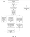
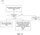
- FIG. 12 illustrates an example method 1200 of a BS determining a paging success, in accordance with some implementations of the present disclosure.
- the paging carrier selection strategy based on Rmax-paging and/or DRX parameter of the UE may be performed.
- the BS may be configured to select a paging carrier using a strategy based on Rmax-paging parameters of the UE and DRX parameters of the UE.
- paging performed according to a carrier selection strategy e.g., Rmax-paging
- the BS may determine whether the paging performed according to the carrier selection strategy (e.g., Rmax-paging parameter) may have failed.
- the BS may not determine that the paging has failed. For instance, the carrier used by the UE may have failed. For example, the UE may have moved to another cell which may have resulted in the paging failing. Additionally or alternatively, the Rmax-paging parameter may have been too small. As shown in step 1203, if the paging message has not failed, the BS may determine that the paging was successful. In the event the BS has determined that the paging has failed, or is unable to determine that the paging was successful, as shown in step 1204, the BS may select a paging carrier selection strategy according to the legacy paging carrier selection strategy and use the legacy Rmax-paging parameters for paging.
- the paging carrier selection strategy according to the legacy paring carrier selection strategy may include not using the paging carrier selection strategy based on the Rmax-paging parameter (or CEL parameter) and/or not using the paging carrier selection strategy based on the DRX parameter of the UE.
- the BS may subsequently perform paging transmission and/or paging monitoring to determine whether the page was successful. Additionally or alternatively, as shown in step 1205, the BS may send a paging message on the paging carrier according to the carrier selection strategy as described herein using the Rmax-paging-fallback parameter (as shown in FIG. 11 ).
- the BS may send a paging message on both the legacy paging carrier (e.g., determined according to the legacy paging carrier selection strategy) and the paging carrier according to the carrier selection strategy as described herein.
- the legacy paging carrier e.g., determined according to the legacy paging carrier selection strategy
- the paging carrier according to the carrier selection strategy as described herein.
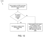
- FIG. 13 illustrates an example method 1300 of a UE's wireless conditions changing, in accordance with some implementations of the present disclosure.
- the paging carrier selection strategy based on Rmax-paging and/or DRX parameter of the UE may be activated (e.g., the network may be configured with the related parameters and the UE supports both carrier selection strategies such that selection strategies based on Rmax-paging parameters of the UE or DRX parameters of the UE may be performed).
- the UE may determine whether wireless conditions have changed (e.g., whether radio conditions have changed).
- a change of the UE's wireless conditions may include the UE determining that the Rmax-paging parameter required for the normal demodulation and scheduling of the PDCCH (CSS-paging) for paging has occurred based on, for instance, reference signal receive power (RSRP) measurements, received signal strength indicator (RSSI) measurements, reference signal received quality (RSRQ) measurements, signal to noise ratio (SINR) measurements, block error rate measurements, or other factors such as the UE selecting a new cell or moving.
- RSRP reference signal receive power
- RSSI received signal strength indicator
- RSRQ reference signal received quality
- SINR signal to noise ratio
- block error rate measurements or other factors such as the UE selecting a new cell or moving.
- the UE may use the legacy paging carrier selection strategy to select the paging carrier and monitor the paging message or select the paging carrier according to the carrier selection strategy as described herein with the Rmax-paging-fallback (as described in FIG. 11 ).
- the UE may use the paging carrier selection strategy based on the Rmax-paging parameter and/or the DRX parameter of the UE to select the paging carrier and monitor the paging message, as discussed herein.
- any reference to an element herein using a designation such as "first,” “second,” and so forth does not generally limit the quantity or order of those elements. Rather, these designations can be used herein as a convenient means of distinguishing between two or more elements or instances of an element. Thus, a reference to first and second elements does not mean that only two elements can be employed, or that the first element must precede the second element in some manner.
- any of the various illustrative logical blocks, modules, processors, means, circuits, methods and functions described in connection with the aspects disclosed herein can be implemented by electronic hardware (e.g., a digital implementation, an analog implementation, or a combination of the two), firmware, various forms of program or design code incorporating instructions (which can be referred to herein, for convenience, as "software” or a "software module), or any combination of these techniques.
- electronic hardware e.g., a digital implementation, an analog implementation, or a combination of the two
- firmware various forms of program or design code incorporating instructions
- software or a "software module”
- IC integrated circuit
- DSP digital signal processor
- ASIC application specific integrated circuit
- FPGA field programmable gate array
- the logical blocks, modules, and circuits can further include antennas and/or transceivers to communicate with various components within the network or within the device.
- a general purpose processor can be a microprocessor, but in the alternative, the processor can be any conventional processor, controller, or state machine.
- a processor can also be implemented as a combination of computing devices, e.g., a combination of a DSP and a microprocessor, a plurality of microprocessors, one or more microprocessors in conjunction with a DSP core, or any other suitable configuration to perform the functions described herein.
- Computer-readable media includes both computer storage media and communication media including any medium that can be enabled to transfer a computer program or code from one place to another.
- a storage media can be any available media that can be accessed by a computer.
- such computer-readable media can include RAM, ROM, EEPROM, CD-ROM or other optical disk storage, magnetic disk storage or other magnetic storage devices, or any other medium that can be used to store desired program code in the form of instructions or data structures and that can be accessed by a computer.
- module refers to software, firmware, hardware, and any combination of these elements for performing the associated functions described herein. Additionally, for purpose of discussion, the various modules are described as discrete modules; however, as would be apparent to one of ordinary skill in the art, two or more modules may be combined to form a single module that performs the associated functions according implementations of the present solution.
- memory or other storage may be employed in implementations of the present solution.
- memory or other storage may be employed in implementations of the present solution.
- any suitable distribution of functionality between different functional units, processing logic elements or domains may be used without detracting from the present solution.
- functionality illustrated to be performed by separate processing logic elements, or controllers may be performed by the same processing logic element, or controller.
- references to specific functional units are only references to a suitable means for providing the described functionality, rather than indicative of a strict logical or physical structure or organization.
Landscapes
- Engineering & Computer Science (AREA)
- Computer Networks & Wireless Communication (AREA)
- Signal Processing (AREA)
- Mobile Radio Communication Systems (AREA)
Claims (15)
- Drahtlos-Kommunikationsverfahren, das aufweist:Empfangen durch eine Basisstation (202) von einer Zugangs- und Mobilitäts-Verwaltungsfunktion (AMF) (305) einer Paging-Fähigkeit eines Benutzergeräts (UE)), die in den Kernnetzwerk-Hilfsinformationen enthalten ist, über eine Anwendungsprotokoll der Nächsten Generation-(NGAP-)Schnittstelle in einem Handover-Prozess,wobei die Paging-Fähigkeit des Benutzergeräts wenigstens eines aufweist von einer Aufwachsignal-Unterstützungsfähigkeit, einer verwandten Aufwachsignal- und erweiterten diskontinuierlichen Empfangszeit (eDRX)-Fähigkeit, einer Gruppenaufwachsignal-Unterstützungsfähigkeit oder einer Frequenzsprungunterstützung für Gruppenaufwachsignale; undwobei die Paging-Fähigkeit des Benutzergeräts zur Auswahl einer Paging-Ressource für Funkzugangsnetzwerk-(RAN-)Paging dient; unddurch die Basisstation (202) auswählen der Paging-Ressource für RAN-Paging gemäß der Paging-Fähigkeit des Benutzergeräts.
- Drahtlos-Kommunikationsverfahren nach Anspruch 1,
wobei die Paging-Fähigkeit des Benutzergeräts in einer Handover-Anforderung enthalten ist, die durch die Basisstation (202) von der AMF (305) empfangen wird. - Drahtlos-Kommunikationsverfahren nach Anspruch 1,
wobei die Paging-Fähigkeit des Benutzergeräts in einer Pfadwechselanforderungs-Bestätigung von der AMF (305) enthalten ist. - Drahtlos-Kommunikationsverfahren nach einem der Ansprüche 1 bis 3, wobei die Paging-Fähigkeit des Benutzergeräts ferner eine Multiband-Unterstützungsfähigkeit aufweist.
- Drahtlos-Kommunikationsverfahren nach einem der Ansprüche 1 bis 4, wobei die Paging-Fähigkeit des Benutzergeräts wenigstens eines aufweist von:
Benutzergerätkategorie, Abdeckungsoptimierungs-(CE-)ModeA-Unterstützungsfähigkeit oder CE-ModeB-Unterstützungsfähigkeit. - Drahtlos-Kommunikationsverfahren, das aufweist:Senden von einer Zugangs- und Mobilitäts-Verwaltungsfunktion (AMF) (305) an eine Basisstation (202) einer Paging-Fähigkeit eines Benutzergeräts (UE), die in den Kernnetzwerk-Hilfsinformationen enthalten ist, über eine Anwendungsprotokoll der Nächsten Generation-(NGAP-)Schnittstelle in einem Handover-Prozess,wobei die Paging-Fähigkeit des Benutzergeräts wenigstens eines aufweist von einer Aufwachsignal-Unterstützungsfähigkeit, einer verwandten Aufwachsignal- und erweiterten diskontinuierlichen Empfangszeit (eDRX)-Fähigkeit, einer Gruppenaufwachsignal-Unterstützungsfähigkeit oder einer Frequenzsprungunterstützung für Gruppenaufwachsignale; undwobei die Paging-Fähigkeit des Benutzergeräts von der Basisstation (202) zur Auswahl einer Paging-Ressource für Funkzugangsnetzwerk-(RAN-)Paging verwendet wird.
- Drahtlos-Kommunikationsverfahren nach Anspruch 6,
wobei die Paging-Fähigkeit des Benutzergeräts in einer Handover-Anforderung enthalten ist, die durch die Basisstation (202) von der AMF (305) empfangen wird. - Drahtlos-Kommunikationsverfahren nach Anspruch 6,
wobei die Paging-Fähigkeit des Benutzergeräts in einer Pfadwechselanforderungs-Bestätigung von der AMF (305) enthalten ist. - Drahtlos-Kommunikationsverfahren nach einem der Ansprüche 6 bis 8, wobei die Paging-Fähigkeit des Benutzergeräts ferner eine Multiband-Unterstützungsfähigkeit aufweist.
- Drahtlos-Kommunikationsverfahren nach einem der Ansprüche 6 bis 9, wobei die Paging-Fähigkeit des Benutzergeräts wenigstens eines aufweist von:
Benutzergerätkategorie, Abdeckungsoptimierungs-(CE-)ModeA-Unterstützungsfähigkeit oder CE-ModeB-Unterstützungsfähigkeit. - Basisstation (202) die aufweist:
wenigstens einen Prozessor (214), der dazu konfiguriert ist:über einen Empfänger (210) von einer Zugangs- und Mobilitäts-Verwaltungsfunktion (AMF) (305) eine Paging-Fähigkeit eines Benutzergeräts (UE), die in den Kernnetzwerk-Hilfsinformationen enthalten ist, über eine Anwendungsprotokoll der Nächsten Generation-(NGAP-)Schnittstelle in einem Handover-Prozess zu empfangen,wobei die Paging-Fähigkeit des Benutzergeräts wenigstens eines aufweist von einer Aufwachsignal-Unterstützungsfähigkeit, einer verwandten Aufwachsignal- und erweiterten diskontinuierlichen Empfangszeit (eDRX)-Fähigkeit, einer Gruppenaufwachsignal-Unterstützungsfähigkeit oder einer Frequenzsprungunterstützung für Gruppenaufwachsignale;wobei die Paging-Fähigkeit des Benutzergeräts zur Auswahl einer Paging-Ressource für Funkzugangsnetzwerk-(RAN-)Paging dient; undAuswählen der Paging-Ressource für RAN-Paging gemäß der Paging-Fähigkeit des Benutzergeräts. - Basisstation (202) nach Anspruch 11, wobei die Paging-Fähigkeit des Benutzergeräts in einer Handover-Anforderung enthalten ist, die durch die Basisstation (202) von der AMF (305) empfangen wird, oder
wobei die Paging-Fähigkeit des Benutzergeräts in einer Pfadwechselanforderungs-Bestätigung enthalten ist, die von der AMF (305) empfangen wird. - Basisstation (202) nach Anspruch 11 oder 12, wobei die Paging-Fähigkeit des Benutzergeräts ferner wenigstens eines aufweist von einer Multiband-Unterstützungsfähigkeit, Benutzergerätkategorie, Abdeckungsoptimierungs-(CE-)ModeA-Unterstützungsfähigkeit oder CE-ModeB-Unterstützungsfähigkeit.
- Zugangs-und Mobilitätsverwaltungsfunktion (AMF) (305), die dazu konfiguriert ist:über einen Sende-Empfänger an eine Basisstation (202) eine Paging-Fähigkeit eines Benutzergeräts (UE), die in den Kernnetzwerk-Hilfsinformationen enthalten ist, über eine Anwendungsprotokoll der Nächsten Generation-(NGAP-)Schnittstelle in einem Handover-Prozess zu senden,wobei die Paging-Fähigkeit des Benutzergeräts wenigstens eines aufweist von einer Aufwachsignal-Unterstützungsfähigkeit, einer verwandten Aufwachsignal- und erweiterten diskontinuierlichen Empfangszeit (eDRX)-Fähigkeit, einer Gruppenaufwachsignal-Unterstützungsfähigkeit oder einer Frequenzsprungunterstützung für Gruppenaufwachsignale; undwobei die Paging-Fähigkeit des Benutzergeräts von der Basisstation (202) zur Auswahl einer Paging-Ressource für RAN-Paging verwendet wird.
- AMF (305) nach Anspruch 14,wobei die Paging-Fähigkeit des Benutzergeräts in einer Handover-Anforderung enthalten ist, die durch die Basisstation (202) von der AMF (305) empfangen wird, oderwobei die Paging-Fähigkeit des Benutzergeräts in einer Pfadwechselanforderungs-Bestätigung von der AMF (305) enthalten ist, und/oderwobei die Paging-Fähigkeit des Benutzergeräts ferner wenigstens eines aufweist von einer Multiband-Unterstützungsfähigkeit, Benutzergerätkategorie, Abdeckungsoptimierungs-(CE)-ModeA-Unterstützungsfähigkeit oder CE-ModeB-Unterstützungsfähigkeit.
Applications Claiming Priority (1)
| Application Number | Priority Date | Filing Date | Title |
|---|---|---|---|
| PCT/CN2020/138363 WO2022133736A1 (en) | 2020-12-22 | 2020-12-22 | System and method for selecting paging resources |
Publications (3)
| Publication Number | Publication Date |
|---|---|
| EP4176645A1 EP4176645A1 (de) | 2023-05-10 |
| EP4176645A4 EP4176645A4 (de) | 2023-07-19 |
| EP4176645B1 true EP4176645B1 (de) | 2025-06-18 |
Family
ID=82157285
Family Applications (1)
| Application Number | Title | Priority Date | Filing Date |
|---|---|---|---|
| EP20966317.8A Active EP4176645B1 (de) | 2020-12-22 | 2020-12-22 | System und verfahren zur auswahl von paging-ressourcen |
Country Status (7)
| Country | Link |
|---|---|
| US (1) | US12356370B2 (de) |
| EP (1) | EP4176645B1 (de) |
| JP (1) | JP7505052B2 (de) |
| KR (1) | KR20230027092A (de) |
| CN (2) | CN117202349A (de) |
| CA (1) | CA3188195A1 (de) |
| WO (1) | WO2022133736A1 (de) |
Families Citing this family (2)
| Publication number | Priority date | Publication date | Assignee | Title |
|---|---|---|---|---|
| WO2022217471A1 (zh) * | 2021-04-13 | 2022-10-20 | 北京小米移动软件有限公司 | 基站寻呼能力的区分方法、装置及通信设备 |
| WO2024234708A1 (en) * | 2024-01-15 | 2024-11-21 | Lenovo (Beijing) Limited | Paging adaptation for network energy saving |
Citations (1)
| Publication number | Priority date | Publication date | Assignee | Title |
|---|---|---|---|---|
| WO2022077315A1 (en) * | 2020-10-15 | 2022-04-21 | Zte Corporation | Method, device, and system for paging resource selection and system information transmission/acquisition in wireless networks |
Family Cites Families (15)
| Publication number | Priority date | Publication date | Assignee | Title |
|---|---|---|---|---|
| US20120314675A1 (en) * | 2010-02-21 | 2012-12-13 | Lg Electronics Inc. | Method for managing carrier aggregation sets, and related devices |
| CN107734643B (zh) * | 2016-08-10 | 2022-02-08 | 中兴通讯股份有限公司 | 一种支持多载波寻呼的配置方法和节点 |
| CN108632949B (zh) * | 2017-03-24 | 2023-06-27 | 华为技术有限公司 | 一种传输信息的方法和网络设备 |
| CN110999440B (zh) | 2017-08-09 | 2023-03-24 | 株式会社Ntt都科摩 | 无线基站及无线通信方法 |
| US11382137B2 (en) * | 2017-10-10 | 2022-07-05 | Telefonaktiebolaget Lm Ericsson (Publ) | Mobile-terminated early data transmission |
| CA3021658A1 (en) * | 2017-10-20 | 2019-04-20 | Comcast Cable Communications, Llc | Non-access stratum capability information |
| CN110351815B (zh) * | 2018-04-04 | 2022-05-27 | 中兴通讯股份有限公司 | 一种寻呼方法、基站及用户设备 |
| US11483895B2 (en) * | 2018-04-13 | 2022-10-25 | Qualcomm Incorporated | Interaction between WUS and RRM measurement |
| US11418998B2 (en) * | 2018-04-17 | 2022-08-16 | Telefonaktiebolaget Lm Ericsson (Publ) | Wireless device, network node, core node and methods for handling radio communication of data |
| CN110636556B (zh) * | 2018-06-22 | 2024-02-20 | 中兴通讯股份有限公司 | 网络处理方法、装置、核心网、基站和可读存储介质 |
| US11490291B2 (en) * | 2019-03-28 | 2022-11-01 | Ofinno, Llc | Handover for closed access group |
| CN111901866B (zh) * | 2020-01-17 | 2025-02-18 | 中兴通讯股份有限公司 | 一种寻呼方法、装置、设备和存储介质 |
| US12477405B2 (en) * | 2020-07-31 | 2025-11-18 | Telefonaktiebolaget Lm Ericsson (Publ) | N2 aspects of integrated access and wireless access backhaul node inter-donor migration |
| WO2022058994A1 (en) * | 2020-09-21 | 2022-03-24 | Telefonaktiebolaget Lm Ericsson (Publ) | QOS UPDATE HANDLING ALTERNATIVES DURING Xn HO |
| US12170979B2 (en) * | 2021-03-29 | 2024-12-17 | Lg Electronics Inc. | Method and apparatus for paging procedure considering network slicing in a wireless communication system |
-
2020
- 2020-12-22 CA CA3188195A patent/CA3188195A1/en active Pending
- 2020-12-22 EP EP20966317.8A patent/EP4176645B1/de active Active
- 2020-12-22 WO PCT/CN2020/138363 patent/WO2022133736A1/en not_active Ceased
- 2020-12-22 JP JP2022581460A patent/JP7505052B2/ja active Active
- 2020-12-22 CN CN202311310788.1A patent/CN117202349A/zh active Pending
- 2020-12-22 CN CN202080104773.8A patent/CN116210296A/zh active Pending
- 2020-12-22 KR KR1020227046051A patent/KR20230027092A/ko active Pending
-
2022
- 2022-12-23 US US18/088,099 patent/US12356370B2/en active Active
Patent Citations (1)
| Publication number | Priority date | Publication date | Assignee | Title |
|---|---|---|---|---|
| WO2022077315A1 (en) * | 2020-10-15 | 2022-04-21 | Zte Corporation | Method, device, and system for paging resource selection and system information transmission/acquisition in wireless networks |
Non-Patent Citations (1)
| Title |
|---|
| "3 rd Generation Partnership Project; Technical Specification Group Radio Access Network; NG-RAN; NG Application Protocol (NGAP) (Release 15)", 2 October 2020 (2020-10-02), XP052300361, Retrieved from the Internet <URL:https://ftp.3gpp.org/3guInternal/3GPP_ultimate_versions_to_be_transposed/sentToDpc/38413-f90.zip 38413-f90.doc> [retrieved on 20201002] * |
Also Published As
| Publication number | Publication date |
|---|---|
| US12356370B2 (en) | 2025-07-08 |
| JP2023534628A (ja) | 2023-08-10 |
| KR20230027092A (ko) | 2023-02-27 |
| EP4176645A4 (de) | 2023-07-19 |
| JP7505052B2 (ja) | 2024-06-24 |
| EP4176645A1 (de) | 2023-05-10 |
| US20230126745A1 (en) | 2023-04-27 |
| CN116210296A (zh) | 2023-06-02 |
| CA3188195A1 (en) | 2022-06-30 |
| WO2022133736A1 (en) | 2022-06-30 |
| CN117202349A (zh) | 2023-12-08 |
Similar Documents
| Publication | Publication Date | Title |
|---|---|---|
| CN112187428B (zh) | 无线电信网络中的网络节点和方法 | |
| US20230080009A1 (en) | Measurement method and apparatus, terminal device and network device | |
| US11265843B2 (en) | Data routing in cellular communication system | |
| CN114631347A (zh) | 一种小区配置方法及装置、终端设备、网络设备 | |
| EP4055970B1 (de) | System und verfahren zur leistungseffizienten herstellung von uplink- und downlink-kommunikation in drahtlosen kommunikationsnetzen | |
| US11546044B2 (en) | Wireless communication method, terminal device and network device | |
| US12507138B2 (en) | Cell accessing method, electronic device, and storage medium | |
| US12356370B2 (en) | System and method for selecting paging resources | |
| CN113170467A (zh) | 波束指示方法、装置及通信设备 | |
| EP4154635B1 (de) | Strahlumschaltung für benutzergerät im inaktiven zustand mit konfigurierten berechtigungen | |
| CN120077709B (zh) | 状态确定、指示方法及装置、通信系统和存储介质 | |
| US20250202657A1 (en) | Serving cell selection method and apparatus | |
| US20250168687A1 (en) | Systems and methods for ue capability report | |
| WO2018203804A1 (en) | Methods for reducing cell search time under coverage enhancement | |
| WO2025235471A1 (en) | Ssb-less scell activation with multiple trs | |
| WO2025015469A1 (zh) | 用于无线通信的方法及设备 | |
| WO2025129664A1 (zh) | 指示方法及通信设备、通信系统、存储介质 | |
| CN118891903A (zh) | 无线通信的方法、终端设备及网络设备 | |
| CN117461361A (zh) | 功率余量信息传输方法、设备和存储介质 | |
| CN118511568A (zh) | 通信方法、终端设备和网络设备 | |
| HK1237152A1 (en) | Network node and method in a wireless telecommunications network |
Legal Events
| Date | Code | Title | Description |
|---|---|---|---|
| STAA | Information on the status of an ep patent application or granted ep patent |
Free format text: STATUS: THE INTERNATIONAL PUBLICATION HAS BEEN MADE |
|
| PUAI | Public reference made under article 153(3) epc to a published international application that has entered the european phase |
Free format text: ORIGINAL CODE: 0009012 |
|
| STAA | Information on the status of an ep patent application or granted ep patent |
Free format text: STATUS: REQUEST FOR EXAMINATION WAS MADE |
|
| 17P | Request for examination filed |
Effective date: 20221228 |
|
| AK | Designated contracting states |
Kind code of ref document: A1 Designated state(s): AL AT BE BG CH CY CZ DE DK EE ES FI FR GB GR HR HU IE IS IT LI LT LU LV MC MK MT NL NO PL PT RO RS SE SI SK SM TR |
|
| A4 | Supplementary search report drawn up and despatched |
Effective date: 20230615 |
|
| RIC1 | Information provided on ipc code assigned before grant |
Ipc: H04W 8/22 20090101ALI20230609BHEP Ipc: H04W 36/00 20090101ALI20230609BHEP Ipc: H04W 68/02 20090101AFI20230609BHEP |
|
| DAV | Request for validation of the european patent (deleted) | ||
| DAX | Request for extension of the european patent (deleted) | ||
| STAA | Information on the status of an ep patent application or granted ep patent |
Free format text: STATUS: EXAMINATION IS IN PROGRESS |
|
| 17Q | First examination report despatched |
Effective date: 20240904 |
|
| REG | Reference to a national code |
Free format text: PREVIOUS MAIN CLASS: H04W0068020000 Ref country code: DE Ref legal event code: R079 Ref document number: 602020053142 Country of ref document: DE Free format text: PREVIOUS MAIN CLASS: H04W0068020000 Ipc: H04W0052020000 |
|
| GRAP | Despatch of communication of intention to grant a patent |
Free format text: ORIGINAL CODE: EPIDOSNIGR1 |
|
| STAA | Information on the status of an ep patent application or granted ep patent |
Free format text: STATUS: GRANT OF PATENT IS INTENDED |
|
| RIC1 | Information provided on ipc code assigned before grant |
Ipc: H04W 36/00 20090101ALN20250213BHEP Ipc: H04W 8/22 20090101ALN20250213BHEP Ipc: H04W 76/28 20180101ALI20250213BHEP Ipc: H04W 68/02 20090101ALI20250213BHEP Ipc: H04W 52/02 20090101AFI20250213BHEP |
|
| INTG | Intention to grant announced |
Effective date: 20250224 |
|
| GRAS | Grant fee paid |
Free format text: ORIGINAL CODE: EPIDOSNIGR3 |
|
| GRAA | (expected) grant |
Free format text: ORIGINAL CODE: 0009210 |
|
| STAA | Information on the status of an ep patent application or granted ep patent |
Free format text: STATUS: THE PATENT HAS BEEN GRANTED |
|
| AK | Designated contracting states |
Kind code of ref document: B1 Designated state(s): AL AT BE BG CH CY CZ DE DK EE ES FI FR GB GR HR HU IE IS IT LI LT LU LV MC MK MT NL NO PL PT RO RS SE SI SK SM TR |
|
| REG | Reference to a national code |
Ref country code: GB Ref legal event code: FG4D |
|
| REG | Reference to a national code |
Ref country code: CH Ref legal event code: EP |
|
| REG | Reference to a national code |
Ref country code: DE Ref legal event code: R096 Ref document number: 602020053142 Country of ref document: DE |
|
| REG | Reference to a national code |
Ref country code: CH Ref legal event code: EP |
|
| REG | Reference to a national code |
Ref country code: IE Ref legal event code: FG4D |
|
| REG | Reference to a national code |
Ref country code: SE Ref legal event code: TRGR |
|
| REG | Reference to a national code |
Ref country code: FI Ref legal event code: FGE |
|
| REG | Reference to a national code |
Ref country code: LT Ref legal event code: MG9D |
|
| PG25 | Lapsed in a contracting state [announced via postgrant information from national office to epo] |
Ref country code: NO Free format text: LAPSE BECAUSE OF FAILURE TO SUBMIT A TRANSLATION OF THE DESCRIPTION OR TO PAY THE FEE WITHIN THE PRESCRIBED TIME-LIMIT Effective date: 20250918 Ref country code: GR Free format text: LAPSE BECAUSE OF FAILURE TO SUBMIT A TRANSLATION OF THE DESCRIPTION OR TO PAY THE FEE WITHIN THE PRESCRIBED TIME-LIMIT Effective date: 20250919 |
|
| PG25 | Lapsed in a contracting state [announced via postgrant information from national office to epo] |
Ref country code: BG Free format text: LAPSE BECAUSE OF FAILURE TO SUBMIT A TRANSLATION OF THE DESCRIPTION OR TO PAY THE FEE WITHIN THE PRESCRIBED TIME-LIMIT Effective date: 20250618 |
|
| PG25 | Lapsed in a contracting state [announced via postgrant information from national office to epo] |
Ref country code: HR Free format text: LAPSE BECAUSE OF FAILURE TO SUBMIT A TRANSLATION OF THE DESCRIPTION OR TO PAY THE FEE WITHIN THE PRESCRIBED TIME-LIMIT Effective date: 20250618 |
|
| PG25 | Lapsed in a contracting state [announced via postgrant information from national office to epo] |
Ref country code: RS Free format text: LAPSE BECAUSE OF FAILURE TO SUBMIT A TRANSLATION OF THE DESCRIPTION OR TO PAY THE FEE WITHIN THE PRESCRIBED TIME-LIMIT Effective date: 20250918 |
|
| REG | Reference to a national code |
Ref country code: NL Ref legal event code: MP Effective date: 20250618 |
|
| PG25 | Lapsed in a contracting state [announced via postgrant information from national office to epo] |
Ref country code: LV Free format text: LAPSE BECAUSE OF FAILURE TO SUBMIT A TRANSLATION OF THE DESCRIPTION OR TO PAY THE FEE WITHIN THE PRESCRIBED TIME-LIMIT Effective date: 20250618 |
|
| PG25 | Lapsed in a contracting state [announced via postgrant information from national office to epo] |
Ref country code: NL Free format text: LAPSE BECAUSE OF FAILURE TO SUBMIT A TRANSLATION OF THE DESCRIPTION OR TO PAY THE FEE WITHIN THE PRESCRIBED TIME-LIMIT Effective date: 20250618 |
|
| PG25 | Lapsed in a contracting state [announced via postgrant information from national office to epo] |
Ref country code: PT Free format text: LAPSE BECAUSE OF FAILURE TO SUBMIT A TRANSLATION OF THE DESCRIPTION OR TO PAY THE FEE WITHIN THE PRESCRIBED TIME-LIMIT Effective date: 20251020 |
|
| REG | Reference to a national code |
Ref country code: AT Ref legal event code: MK05 Ref document number: 1805354 Country of ref document: AT Kind code of ref document: T Effective date: 20250618 |
|
| PG25 | Lapsed in a contracting state [announced via postgrant information from national office to epo] |
Ref country code: IS Free format text: LAPSE BECAUSE OF FAILURE TO SUBMIT A TRANSLATION OF THE DESCRIPTION OR TO PAY THE FEE WITHIN THE PRESCRIBED TIME-LIMIT Effective date: 20251018 |
|
| PGFP | Annual fee paid to national office [announced via postgrant information from national office to epo] |
Ref country code: DE Payment date: 20250930 Year of fee payment: 6 |
|
| PGFP | Annual fee paid to national office [announced via postgrant information from national office to epo] |
Ref country code: GB Payment date: 20251001 Year of fee payment: 6 |
|
| PG25 | Lapsed in a contracting state [announced via postgrant information from national office to epo] |
Ref country code: AT Free format text: LAPSE BECAUSE OF FAILURE TO SUBMIT A TRANSLATION OF THE DESCRIPTION OR TO PAY THE FEE WITHIN THE PRESCRIBED TIME-LIMIT Effective date: 20250618 Ref country code: SM Free format text: LAPSE BECAUSE OF FAILURE TO SUBMIT A TRANSLATION OF THE DESCRIPTION OR TO PAY THE FEE WITHIN THE PRESCRIBED TIME-LIMIT Effective date: 20250618 |
|
| PGFP | Annual fee paid to national office [announced via postgrant information from national office to epo] |
Ref country code: FI Payment date: 20251211 Year of fee payment: 6 Ref country code: IT Payment date: 20251121 Year of fee payment: 6 |
|
| PGFP | Annual fee paid to national office [announced via postgrant information from national office to epo] |
Ref country code: FR Payment date: 20251110 Year of fee payment: 6 |
|
| PGFP | Annual fee paid to national office [announced via postgrant information from national office to epo] |
Ref country code: SE Payment date: 20251001 Year of fee payment: 6 |
|
| PG25 | Lapsed in a contracting state [announced via postgrant information from national office to epo] |
Ref country code: CZ Free format text: LAPSE BECAUSE OF FAILURE TO SUBMIT A TRANSLATION OF THE DESCRIPTION OR TO PAY THE FEE WITHIN THE PRESCRIBED TIME-LIMIT Effective date: 20250618 |
|
| PG25 | Lapsed in a contracting state [announced via postgrant information from national office to epo] |
Ref country code: PL Free format text: LAPSE BECAUSE OF FAILURE TO SUBMIT A TRANSLATION OF THE DESCRIPTION OR TO PAY THE FEE WITHIN THE PRESCRIBED TIME-LIMIT Effective date: 20250618 |
|
| PG25 | Lapsed in a contracting state [announced via postgrant information from national office to epo] |
Ref country code: EE Free format text: LAPSE BECAUSE OF FAILURE TO SUBMIT A TRANSLATION OF THE DESCRIPTION OR TO PAY THE FEE WITHIN THE PRESCRIBED TIME-LIMIT Effective date: 20250618 |
|
| PG25 | Lapsed in a contracting state [announced via postgrant information from national office to epo] |
Ref country code: SK Free format text: LAPSE BECAUSE OF FAILURE TO SUBMIT A TRANSLATION OF THE DESCRIPTION OR TO PAY THE FEE WITHIN THE PRESCRIBED TIME-LIMIT Effective date: 20250618 |
|
| PG25 | Lapsed in a contracting state [announced via postgrant information from national office to epo] |
Ref country code: ES Free format text: LAPSE BECAUSE OF FAILURE TO SUBMIT A TRANSLATION OF THE DESCRIPTION OR TO PAY THE FEE WITHIN THE PRESCRIBED TIME-LIMIT Effective date: 20250618 |