EP4175167A1 - Common mode current controller for inverter - Google Patents
Common mode current controller for inverter Download PDFInfo
- Publication number
- EP4175167A1 EP4175167A1 EP21841697.2A EP21841697A EP4175167A1 EP 4175167 A1 EP4175167 A1 EP 4175167A1 EP 21841697 A EP21841697 A EP 21841697A EP 4175167 A1 EP4175167 A1 EP 4175167A1
- Authority
- EP
- European Patent Office
- Prior art keywords
- direct current
- impedance
- common mode
- ground
- busbar capacitor
- Prior art date
- Legal status (The legal status is an assumption and is not a legal conclusion. Google has not performed a legal analysis and makes no representation as to the accuracy of the status listed.)
- Pending
Links
Images



Classifications
-
- H—ELECTRICITY
- H02—GENERATION; CONVERSION OR DISTRIBUTION OF ELECTRIC POWER
- H02S—GENERATION OF ELECTRIC POWER BY CONVERSION OF INFRARED RADIATION, VISIBLE LIGHT OR ULTRAVIOLET LIGHT, e.g. USING PHOTOVOLTAIC [PV] MODULES
- H02S40/00—Components or accessories in combination with PV modules, not provided for in groups H02S10/00 - H02S30/00
- H02S40/30—Electrical components
- H02S40/32—Electrical components comprising DC/AC inverter means associated with the PV module itself, e.g. AC modules
-
- H—ELECTRICITY
- H02—GENERATION; CONVERSION OR DISTRIBUTION OF ELECTRIC POWER
- H02J—ELECTRIC POWER NETWORKS; CIRCUIT ARRANGEMENTS OR SYSTEMS FOR SUPPLYING OR DISTRIBUTING ELECTRIC POWER; SYSTEMS FOR STORING ELECTRIC ENERGY
- H02J1/00—Circuit arrangements for DC mains or DC distribution networks
- H02J1/02—Arrangements for reducing harmonics or ripples
-
- H—ELECTRICITY
- H02—GENERATION; CONVERSION OR DISTRIBUTION OF ELECTRIC POWER
- H02M—APPARATUS FOR CONVERSION BETWEEN AC AND AC, BETWEEN AC AND DC, OR BETWEEN DC AND DC, AND FOR USE WITH MAINS OR SIMILAR POWER SUPPLY SYSTEMS; CONVERSION OF DC OR AC INPUT POWER INTO SURGE OUTPUT POWER; CONTROL OR REGULATION THEREOF
- H02M7/00—Conversion of AC power input into DC power output; Conversion of DC power input into AC power output
- H02M7/42—Conversion of DC power input into AC power output without possibility of reversal
- H02M7/44—Conversion of DC power input into AC power output without possibility of reversal by static converters
- H02M7/48—Conversion of DC power input into AC power output without possibility of reversal by static converters using discharge tubes with control electrode or semiconductor devices with control electrode
- H02M7/53—Conversion of DC power input into AC power output without possibility of reversal by static converters using discharge tubes with control electrode or semiconductor devices with control electrode using devices of a triode or transistor type requiring continuous application of a control signal
- H02M7/537—Conversion of DC power input into AC power output without possibility of reversal by static converters using discharge tubes with control electrode or semiconductor devices with control electrode using devices of a triode or transistor type requiring continuous application of a control signal using semiconductor devices only, e.g. single switched pulse inverters
-
- H—ELECTRICITY
- H02—GENERATION; CONVERSION OR DISTRIBUTION OF ELECTRIC POWER
- H02J—ELECTRIC POWER NETWORKS; CIRCUIT ARRANGEMENTS OR SYSTEMS FOR SUPPLYING OR DISTRIBUTING ELECTRIC POWER; SYSTEMS FOR STORING ELECTRIC ENERGY
- H02J3/00—Circuit arrangements for AC mains or AC distribution networks
- H02J3/38—Arrangements for feeding a single network from two or more generators or sources in parallel; Arrangements for feeding already energised networks from additional generators or sources in parallel
- H02J3/381—Dispersed generators
-
- H—ELECTRICITY
- H02—GENERATION; CONVERSION OR DISTRIBUTION OF ELECTRIC POWER
- H02J—ELECTRIC POWER NETWORKS; CIRCUIT ARRANGEMENTS OR SYSTEMS FOR SUPPLYING OR DISTRIBUTING ELECTRIC POWER; SYSTEMS FOR STORING ELECTRIC ENERGY
- H02J7/00—Circuit arrangements for charging or discharging batteries or for supplying loads from batteries
- H02J7/34—Parallel operation in networks using both storage and other DC sources, e.g. providing buffering
- H02J7/35—Parallel operation in networks using both storage and other DC sources, e.g. providing buffering with light sensitive cells
-
- H—ELECTRICITY
- H02—GENERATION; CONVERSION OR DISTRIBUTION OF ELECTRIC POWER
- H02M—APPARATUS FOR CONVERSION BETWEEN AC AND AC, BETWEEN AC AND DC, OR BETWEEN DC AND DC, AND FOR USE WITH MAINS OR SIMILAR POWER SUPPLY SYSTEMS; CONVERSION OF DC OR AC INPUT POWER INTO SURGE OUTPUT POWER; CONTROL OR REGULATION THEREOF
- H02M1/00—Details of apparatus for conversion
- H02M1/12—Arrangements for reducing harmonics from AC input or output
- H02M1/123—Suppression of common mode voltage or current
-
- H—ELECTRICITY
- H02—GENERATION; CONVERSION OR DISTRIBUTION OF ELECTRIC POWER
- H02M—APPARATUS FOR CONVERSION BETWEEN AC AND AC, BETWEEN AC AND DC, OR BETWEEN DC AND DC, AND FOR USE WITH MAINS OR SIMILAR POWER SUPPLY SYSTEMS; CONVERSION OF DC OR AC INPUT POWER INTO SURGE OUTPUT POWER; CONTROL OR REGULATION THEREOF
- H02M7/00—Conversion of AC power input into DC power output; Conversion of DC power input into AC power output
- H02M7/003—Constructional details, e.g. physical layout, assembly, wiring or busbar connections
-
- H—ELECTRICITY
- H02—GENERATION; CONVERSION OR DISTRIBUTION OF ELECTRIC POWER
- H02M—APPARATUS FOR CONVERSION BETWEEN AC AND AC, BETWEEN AC AND DC, OR BETWEEN DC AND DC, AND FOR USE WITH MAINS OR SIMILAR POWER SUPPLY SYSTEMS; CONVERSION OF DC OR AC INPUT POWER INTO SURGE OUTPUT POWER; CONTROL OR REGULATION THEREOF
- H02M7/00—Conversion of AC power input into DC power output; Conversion of DC power input into AC power output
- H02M7/42—Conversion of DC power input into AC power output without possibility of reversal
- H02M7/44—Conversion of DC power input into AC power output without possibility of reversal by static converters
-
- H—ELECTRICITY
- H02—GENERATION; CONVERSION OR DISTRIBUTION OF ELECTRIC POWER
- H02M—APPARATUS FOR CONVERSION BETWEEN AC AND AC, BETWEEN AC AND DC, OR BETWEEN DC AND DC, AND FOR USE WITH MAINS OR SIMILAR POWER SUPPLY SYSTEMS; CONVERSION OF DC OR AC INPUT POWER INTO SURGE OUTPUT POWER; CONTROL OR REGULATION THEREOF
- H02M7/00—Conversion of AC power input into DC power output; Conversion of DC power input into AC power output
- H02M7/42—Conversion of DC power input into AC power output without possibility of reversal
- H02M7/44—Conversion of DC power input into AC power output without possibility of reversal by static converters
- H02M7/48—Conversion of DC power input into AC power output without possibility of reversal by static converters using discharge tubes with control electrode or semiconductor devices with control electrode
-
- H—ELECTRICITY
- H02—GENERATION; CONVERSION OR DISTRIBUTION OF ELECTRIC POWER
- H02S—GENERATION OF ELECTRIC POWER BY CONVERSION OF INFRARED RADIATION, VISIBLE LIGHT OR ULTRAVIOLET LIGHT, e.g. USING PHOTOVOLTAIC [PV] MODULES
- H02S40/00—Components or accessories in combination with PV modules, not provided for in groups H02S10/00 - H02S30/00
- H02S40/30—Electrical components
-
- H—ELECTRICITY
- H02—GENERATION; CONVERSION OR DISTRIBUTION OF ELECTRIC POWER
- H02J—ELECTRIC POWER NETWORKS; CIRCUIT ARRANGEMENTS OR SYSTEMS FOR SUPPLYING OR DISTRIBUTING ELECTRIC POWER; SYSTEMS FOR STORING ELECTRIC ENERGY
- H02J2101/00—Supply or distribution of decentralised, dispersed or local electric power generation
- H02J2101/20—Dispersed power generation using renewable energy sources
- H02J2101/22—Solar energy
- H02J2101/24—Photovoltaics
-
- H—ELECTRICITY
- H02—GENERATION; CONVERSION OR DISTRIBUTION OF ELECTRIC POWER
- H02M—APPARATUS FOR CONVERSION BETWEEN AC AND AC, BETWEEN AC AND DC, OR BETWEEN DC AND DC, AND FOR USE WITH MAINS OR SIMILAR POWER SUPPLY SYSTEMS; CONVERSION OF DC OR AC INPUT POWER INTO SURGE OUTPUT POWER; CONTROL OR REGULATION THEREOF
- H02M1/00—Details of apparatus for conversion
- H02M1/0067—Converter structures employing plural converter units, other than for parallel operation of the units on a single load
- H02M1/007—Plural converter units in cascade
-
- H—ELECTRICITY
- H02—GENERATION; CONVERSION OR DISTRIBUTION OF ELECTRIC POWER
- H02M—APPARATUS FOR CONVERSION BETWEEN AC AND AC, BETWEEN AC AND DC, OR BETWEEN DC AND DC, AND FOR USE WITH MAINS OR SIMILAR POWER SUPPLY SYSTEMS; CONVERSION OF DC OR AC INPUT POWER INTO SURGE OUTPUT POWER; CONTROL OR REGULATION THEREOF
- H02M3/00—Conversion of DC power input into DC power output
-
- H—ELECTRICITY
- H02—GENERATION; CONVERSION OR DISTRIBUTION OF ELECTRIC POWER
- H02M—APPARATUS FOR CONVERSION BETWEEN AC AND AC, BETWEEN AC AND DC, OR BETWEEN DC AND DC, AND FOR USE WITH MAINS OR SIMILAR POWER SUPPLY SYSTEMS; CONVERSION OF DC OR AC INPUT POWER INTO SURGE OUTPUT POWER; CONTROL OR REGULATION THEREOF
- H02M7/00—Conversion of AC power input into DC power output; Conversion of DC power input into AC power output
- H02M7/42—Conversion of DC power input into AC power output without possibility of reversal
- H02M7/44—Conversion of DC power input into AC power output without possibility of reversal by static converters
- H02M7/48—Conversion of DC power input into AC power output without possibility of reversal by static converters using discharge tubes with control electrode or semiconductor devices with control electrode
- H02M7/483—Converters with outputs that each can have more than two voltages levels
-
- Y—GENERAL TAGGING OF NEW TECHNOLOGICAL DEVELOPMENTS; GENERAL TAGGING OF CROSS-SECTIONAL TECHNOLOGIES SPANNING OVER SEVERAL SECTIONS OF THE IPC; TECHNICAL SUBJECTS COVERED BY FORMER USPC CROSS-REFERENCE ART COLLECTIONS [XRACs] AND DIGESTS
- Y02—TECHNOLOGIES OR APPLICATIONS FOR MITIGATION OR ADAPTATION AGAINST CLIMATE CHANGE
- Y02E—REDUCTION OF GREENHOUSE GAS [GHG] EMISSIONS, RELATED TO ENERGY GENERATION, TRANSMISSION OR DISTRIBUTION
- Y02E10/00—Energy generation through renewable energy sources
- Y02E10/50—Photovoltaic [PV] energy
- Y02E10/56—Power conversion systems, e.g. maximum power point trackers
Definitions
- This application relates to the field of power electronics technologies, and in particular, to a common mode current controller of an inverter.
- the photovoltaic power generation is to convert solar radiation energy into electric energy by using a photovoltaic effect of a semiconductor material. For example, a direct current is generated under illumination by using a photovoltaic module.
- a photovoltaic power generation system and a wind turbine generator are usually direct current voltage sources.
- a generated direct current is converted into an alternating current by using an inverter, and then the alternating current is tied to a power grid for transmission.
- An alternating current output by a grid-tied inverter (Grid-Tie Inverter, IGT) needs to be synchronized with the mains in the power grid in terms of a frequency and a phase, so that the alternating current is transmitted by using the power grid.
- IGT Grid-Tie Inverter
- a positive direct current busbar and a negative direct current busbar of an inverter usually float.
- the positive direct current busbar and the negative direct current busbar may have asymmetric impedance to ground, leading to different potentials to ground, and further leading to a potential difference between a midpoint of a direct current busbar capacitor and a protective earthing (Protecting Earthing, PE) end, also referred to as a grounding end.
- the potential difference is essentially a common mode voltage.
- a parasitic capacitor to ground of the photovoltaic power generation system, the photovoltaic power generation system, and the power grid form a loop, and a large common mode current is formed based on the common mode voltage, and is also referred to as a leakage current (Residual Current, RC).
- the common mode current formed at a grid-tied instant is usually large.
- a related potential difference may be as high as several hundred volts in a severe case, to interfere with detection and control of the system and cause an operation fault, for example, trigger an action of a leakage current protector and even lead to a disconnection of the grid-tied inverter.
- a manner is to modulate a common mode voltage by using a modulation algorithm such as pulse width modulation PWM.
- a modulation algorithm such as pulse width modulation PWM.
- complex technical means such as phase detection and compensation are used in this manner, causing a complex structure.
- Another manner is to dispose a compensation power supply between a main circuit of an inverter and the ground, to compensate for an inverter-to-ground common mode voltage to obtain a target value.
- the target value that is to be obtained through compensation needs to be calculated based on an alternating current port-to-ground voltage collected in real time, increasing a degree of complexity of a system design and costs of the system design.
- Still another manner is to dispose, for a relay between an AC end of a grid-tied inverter and a power grid, an impulse current suppression branch connected to the relay in parallel, to suppress an impulse leakage current generated at an instant of closing the relay.
- an impulse current suppression branch connected to the relay in parallel, to suppress an impulse leakage current generated at an instant of closing the relay.
- This application aims to provide a common mode current controller of an inverter.
- An application scenario of the common mode current controller includes but is not limited to a grid-tied photovoltaic inverter, a photovoltaic system connected to a power grid, and another scenario in which impact of a common mode current generated at a grid-tied instant needs to be controlled.
- the common mode current controller includes a switch and an impedance correction circuit. One end of the impedance correction circuit is grounded, and the other end of the impedance correction circuit is connected to one end of the switch.
- the other end of the switch is connected to one terminal in a positive terminal and a negative terminal of the direct current busbar capacitor, so that the common mode current controller and at least a part of an intrinsic ground impedance part of the direct current busbar capacitor are connected in parallel between the one terminal in the positive terminal and the negative terminal of the direct current busbar capacitor and the ground.
- the common mode current controller is configured to: when a midpoint-to-ground voltage of the direct current busbar capacitor exceeds a threshold range, close the switch to adjust impedance matching between positive terminal-to-ground equivalent impedance of the direct current busbar capacitor and negative terminal-to-ground equivalent impedance of the direct current busbar capacitor, so that the inverter can pre-control a magnitude of a common mode current generated when the inverter is grid-tied.
- the common mode current controller implements introduction of the impedance correction circuit and adjustment of impedance matching based on the midpoint-to-ground voltage of the direct current busbar capacitor, so that the magnitude of the common mode current generated when the inverter is grid-tied can be pre-controlled before a grid-tied switch of the inverter is closed, to help reduce a degree of complexity of a system design and reduce costs of the system design.
- an embodiment of this application provides a common mode current controller of an inverter.
- the common mode current controller is connected between a direct current busbar capacitor of the inverter and a direct current input voltage source of the inverter, a positive terminal and a negative terminal of the direct current busbar capacitor are respectively connected to a positive terminal and a negative terminal of the direct current input voltage source, and the common mode current controller includes a switch and an impedance correction circuit.
- One end of the impedance correction circuit is grounded, the other end of the impedance correction circuit is connected to one end of the switch, and the other end of the switch is connected to one terminal in the positive terminal and the negative terminal of the direct current busbar capacitor, so that the common mode current controller and at least a part of an intrinsic ground impedance part of the direct current busbar capacitor are connected in parallel between the one terminal in the positive terminal and the negative terminal of the direct current busbar capacitor and the ground.
- the common mode current controller is configured to: when a midpoint-to-ground voltage of the direct current busbar capacitor exceeds a threshold range, close the switch to adjust impedance matching between positive terminal-to-ground equivalent impedance of the direct current busbar capacitor and negative terminal-to-ground equivalent impedance of the direct current busbar capacitor, so that the inverter can pre-control a magnitude of a common mode current generated when the inverter is grid-tied.
- introduction of the impedance correction circuit and adjustment of impedance matching are implemented based on the midpoint-to-ground voltage of the direct current busbar capacitor, so that the magnitude of the common mode current generated when the inverter is grid-tied can be pre-controlled before a grid-tied switch of the inverter is closed, to help reduce a degree of complexity of a system design and reduce costs of the system design.
- the midpoint-to-ground voltage of the direct current busbar capacitor is determined based on a positive terminal voltage of the direct current busbar capacitor and a negative terminal voltage of the direct current busbar capacitor.
- the midpoint-to-ground voltage is indirectly determined based on the positive terminal voltage and the negative terminal voltage of the direct current busbar capacitor, to implement introduction of the impedance correction circuit and adjustment of impedance matching based on the midpoint-to-ground voltage of the direct current busbar capacitor, so that the magnitude of the common mode current generated when the inverter is grid-tied can be pre-controlled before the grid-tied switch of the inverter is closed,, to help reduce the degree of complexity of the system design and reduce the costs of the system design.
- the other end of the switch is connected to the positive terminal of the direct current busbar capacitor, and when the midpoint-to-ground voltage of the direct current busbar capacitor is greater than a first threshold, the switch is closed, so that the impedance correction circuit and a positive terminal part of the intrinsic ground impedance part of the direct current busbar capacitor are connected in parallel between the positive terminal of the direct current busbar capacitor and the ground, to reduce a magnitude of the positive terminal-to-ground equivalent impedance of the direct current busbar capacitor.
- the switch is closed, so that the impedance correction circuit and the positive terminal part of the intrinsic ground impedance part of the direct current busbar capacitor are connected in parallel, to implement introduction of the impedance correction circuit and adjustment of impedance matching based on the midpoint-to-ground voltage of the direct current busbar capacitor, so that the magnitude of the common mode current generated when the inverter is grid-tied can be pre-controlled before the grid-tied switch of the inverter is closed, to help reduce the degree of complexity of the system design and reduce the costs of the system design.
- the other end of the switch is connected to the negative terminal of the direct current busbar capacitor, and when the midpoint-to-ground voltage of the direct current busbar capacitor is less than a first threshold, the switch is closed, so that the impedance correction circuit and a negative terminal part of the intrinsic ground impedance part of the direct current busbar capacitor are connected in parallel between the negative terminal of the direct current busbar capacitor and the ground, to reduce a magnitude of the negative terminal-to-ground equivalent impedance of the direct current busbar capacitor.
- the switch is closed, so that the impedance correction circuit and the negative terminal part of the intrinsic ground impedance part of the direct current busbar capacitor are connected in parallel, to implement introduction of the impedance correction circuit and adjustment of impedance matching based on the midpoint-to-ground voltage of the direct current busbar capacitor, so that the magnitude of the common mode current generated when the inverter is grid-tied can be pre-controlled before the grid-tied switch of the inverter is closed, to help reduce the degree of complexity of the system design and reduce the costs of the system design.
- an impedance value of the impedance correction circuit is adjustable, and the impedance value of the impedance correction circuit is adjusted, so that the positive terminal-to-ground equivalent impedance of the direct current busbar capacitor matches the negative terminal-to-ground equivalent impedance of the direct current busbar capacitor.
- the impedance value of the impedance correction circuit is adjusted, so that the positive terminal-to-ground equivalent impedance of the direct current busbar capacitor matches the negative terminal-to-ground equivalent impedance of the direct current busbar capacitor, to implement introduction of the impedance correction circuit and adjustment of impedance matching based on the midpoint-to-ground voltage of the direct current busbar capacitor, so that the magnitude of the common mode current generated when the inverter is grid-tied can be pre-controlled before the grid-tied switch of the inverter is closed, to help reduce the degree of complexity of the system design and reduce the costs of the system design.
- the inverter includes a direct current-direct current DC-DC converter and a direct current-alternating current DC-AC converter, and the common mode current controller is between the DC-DC converter and the DC-AC converter.
- the common mode current controller is disposed between the DC-DC converter and the DC-AC converter, to perform control on a DC side of the inverter, and help simplify the system design and reduce the costs.
- the common mode current controller is further configured to control to release a residual charge of a Y capacitor at a terminal of the inverter.
- the inverter is a grid-tied inverter of a photovoltaic power generation system
- the common mode current controller is configured to control a magnitude of a common mode current generated when the photovoltaic power generation system is grid-tied.
- introduction of the impedance correction circuit and adjustment of impedance matching are implemented based on the midpoint ground voltage of the direct current busbar capacitor, so that the magnitude of the common mode current generated when the photovoltaic power generation system is grid-tied can be pre-controlled before a grid-tied switch of the photovoltaic power generation system is closed, to help reduce the degree of complexity of the system design and reduce the costs of the system design.
- an embodiment of this application provides a common mode current controller of an inverter.
- the common mode current controller is connected between a direct current busbar capacitor of the inverter and a direct current input voltage source of the inverter, a positive terminal and a negative terminal of the direct current busbar capacitor are respectively connected to a positive terminal and a negative terminal of the direct current input voltage source, and the common mode current controller includes: a first switch, where one end of the first switch is connected to the positive terminal of the direct current busbar capacitor; a second switch, where one end of the second switch is connected to the negative terminal of the direct current busbar capacitor; a first impedance correction circuit, where one end of the first impedance correction circuit is grounded, and the other end of the first impedance correction circuit is connected to the other end of the first switch; and a second impedance correction circuit, where one end of the second impedance correction circuit is grounded, and the other end of the second impedance correction circuit is connected to the other end of the second switch.
- the common mode current controller is configured to: when a midpoint-to-ground voltage of the direct current busbar capacitor is greater than a first threshold, close the first switch, and open the second switch, so that the first impedance correction circuit and a positive terminal part of an intrinsic ground impedance part of the direct current busbar capacitor are connected in parallel between the positive terminal of the direct current busbar capacitor and the ground, to reduce a magnitude of positive terminal-to-ground equivalent impedance of the direct current busbar capacitor.
- the common mode current controller is configured to: when the midpoint-to-ground voltage of the direct current busbar capacitor is less than a second threshold, close the second switch, and open the first switch, so that the second impedance correction circuit and a negative terminal part of the intrinsic ground impedance part of the direct current busbar capacitor are connected in parallel between the negative terminal of the direct current busbar capacitor and the ground, to reduce a magnitude of negative terminal-to-ground equivalent impedance of the direct current busbar capacitor.
- the common mode current controller adjusts impedance matching between the positive terminal-to-ground equivalent impedance of the direct current busbar capacitor and the negative terminal-to-ground equivalent impedance of the direct current busbar capacitor, so that the inverter can pre-control a magnitude of a common mode current generated when the inverter is grid-tied.
- introduction of the first impedance correction circuit or the second impedance correction circuit and adjustment of impedance matching are implemented based on the midpoint-to-ground voltage of the direct current busbar capacitor, so that the magnitude of the common mode current generated when the inverter is grid-tied can be pre-controlled before a grid-tied switch of the inverter is closed, to help reduce a degree of complexity of a system design and reduce costs of the system design.
- the midpoint-to-ground voltage of the direct current busbar capacitor is determined based on a positive terminal voltage of the direct current busbar capacitor and a negative terminal voltage of the direct current busbar capacitor.
- the midpoint-to-ground voltage is indirectly determined based on the positive terminal voltage and the negative terminal voltage of the direct current busbar capacitor, to implement introduction of the impedance correction circuit and adjustment of impedance matching based on the midpoint-to-ground voltage of the direct current busbar capacitor, so that the magnitude of the common mode current generated when the inverter is grid-tied can be pre-controlled before the grid-tied switch of the inverter is closed, to help reduce the degree of complexity of the system design and reduce the costs of the system design.
- an impedance value of the first impedance correction circuit and an impedance value of the second impedance correction circuit are both adjustable, and the impedance value of the first impedance correction circuit and the impedance value of the second impedance correction circuit are adjusted, so that the positive terminal-to-ground equivalent impedance of the direct current busbar capacitor matches the negative terminal-to-ground equivalent impedance of the direct current busbar capacitor.
- the impedance value of the first impedance correction circuit and the impedance value of the second impedance correction circuit are adjusted, so that the positive terminal-to-ground equivalent impedance of the direct current busbar capacitor matches the negative terminal-to-ground equivalent impedance of the direct current busbar capacitor, to implement introduction of an impedance correction circuit and adjustment of impedance matching based on the midpoint-to-ground voltage of the direct current busbar capacitor, so that the magnitude of the common mode current generated when the inverter is grid-tied can be pre-controlled before the grid-tied switch of the inverter is closed, to help reduce the degree of complexity of the system design and reduce the costs of the system design.
- the inverter includes a direct current-direct current DC-DC converter and a direct current-alternating current DC-AC converter, and the common mode current controller is between the DC-DC converter and the DC-AC converter.
- the common mode current controller is disposed between the DC-DC converter and the DC-AC converter, to perform control on a DC side of the inverter, and help simplify the system design and reduce the costs.
- the common mode current controller is further configured to control to release a residual charge of a Y capacitor at a terminal of the inverter.
- the inverter is a grid-tied inverter of a photovoltaic power generation system
- the common mode current controller is configured to control a magnitude of a common mode current generated when the photovoltaic power generation system is grid-tied.
- introduction of the impedance correction circuit and adjustment of impedance matching are implemented based on the midpoint ground voltage of the direct current busbar capacitor, so that the magnitude of the common mode current generated when the photovoltaic power generation system is grid-tied can be pre-controlled before the grid-tied switch of the photovoltaic power generation system is closed, to help reduce the degree of complexity of the system design and reduce the costs of the system design.
- an embodiment of this application provides a common mode current controller of an inverter.
- the common mode current controller is connected between a direct current busbar capacitor of the inverter and a direct current input voltage source of the inverter, a positive terminal and a negative terminal of the direct current busbar capacitor are respectively connected to a positive terminal and a negative terminal of the direct current input voltage source, and the common mode current controller includes: a single-pole triple-throw switch, where a non-movable end of the single-pole triple-throw switch is grounded, and a movable end of the single-pole triple-throw switch includes a first movable end, a second movable end, and a third movable end; a first impedance correction circuit, where one end of the first impedance correction circuit is connected to the first movable end of the single-pole triple-throw switch, and the other end of the first impedance correction part is connected to the positive terminal of the direct current busbar capacitor; and a second impedance correction circuit,
- the common mode current controller is configured to: when a midpoint-to-ground voltage of the direct current busbar capacitor is greater than a first threshold, switch the single-pole triple-throw switch to the first movable end, so that the first impedance correction circuit and a positive terminal part of an intrinsic ground impedance part of the direct current busbar capacitor are connected in parallel between the positive terminal of the direct current busbar capacitor and the ground, to reduce a magnitude of positive terminal-to-ground equivalent impedance of the direct current busbar capacitor.
- the common mode current controller is configured to: when the midpoint-to-ground voltage of the direct current busbar capacitor is less than a second threshold, switch the single-pole triple-throw switch to the second movable end, so that the second impedance correction circuit and a negative terminal part of the intrinsic ground impedance part of the direct current busbar capacitor are connected in parallel between the negative terminal of the direct current busbar capacitor and the ground, to reduce a magnitude of negative terminal-to-ground equivalent impedance of the direct current busbar capacitor.
- the common mode current controller adjusts impedance matching between the positive terminal-to-ground equivalent impedance of the direct current busbar capacitor and the negative terminal-to-ground equivalent impedance of the direct current busbar capacitor, so that the inverter can pre-control a magnitude of a common mode current generated when the inverter is grid-tied.
- introduction of the first impedance correction circuit or the second impedance correction circuit and adjustment of impedance matching are implemented based on the midpoint-to-ground voltage of the direct current busbar capacitor, so that the magnitude of the common mode current generated when the inverter is grid-tied can be pre-controlled before a grid-tied switch of the inverter is closed, to help reduce a degree of complexity of a system design and reduce costs of the system design.
- the midpoint-to-ground voltage of the direct current busbar capacitor is determined based on a positive terminal voltage of the direct current busbar capacitor and a negative terminal voltage of the direct current busbar capacitor.
- the midpoint-to-ground voltage is indirectly determined based on the positive terminal voltage and the negative terminal voltage of the direct current busbar capacitor, to implement introduction of an impedance correction circuit and adjustment of impedance matching based on the midpoint-to-ground voltage of the direct current busbar capacitor, so that the magnitude of the common mode current generated when the inverter is grid-tied can be pre-controlled before the grid-tied switch of the inverter is closed, to help reduce the degree of complexity of the system design and reduce the costs of the system design.
- an impedance value of the first impedance correction circuit and an impedance value of the second impedance correction circuit are both adjustable, and the impedance value of the first impedance correction circuit and the impedance value of the second impedance correction circuit are adjusted, so that the positive terminal-to-ground equivalent impedance of the direct current busbar capacitor matches the negative terminal-to-ground equivalent impedance of the direct current busbar capacitor.
- the impedance value of the first impedance correction circuit and the impedance value of the second impedance correction circuit are adjusted, so that the positive terminal-to-ground equivalent impedance of the direct current busbar capacitor matches the negative terminal-to-ground equivalent impedance of the direct current busbar capacitor, to implement introduction of an impedance correction circuit and adjustment of impedance matching based on the midpoint-to-ground voltage of the direct current busbar capacitor, so that the magnitude of the common mode current generated when the inverter is grid-tied can be pre-controlled before the grid-tied switch of the inverter is closed, to help reduce the degree of complexity of the system design and reduce the costs of the system design.
- the inverter includes a direct current-direct current DC-DC converter and a direct current-alternating current DC-AC converter, and the common mode current controller is between the DC-DC converter and the DC-AC converter.
- the common mode current controller is disposed between the DC-DC converter and the DC-AC converter, to perform control on a DC side of the inverter, and help simplify the system design and reduce the costs.
- the common mode current controller is further configured to control to release a residual charge of a Y capacitor at a terminal of the inverter.
- the inverter is a grid-tied inverter of a photovoltaic power generation system
- the common mode current controller is configured to control a magnitude of a common mode current generated when the photovoltaic power generation system is grid-tied.
- introduction of the impedance correction circuit and adjustment of impedance matching are implemented based on the midpoint ground voltage of the direct current busbar capacitor, so that the magnitude of the common mode current generated when the photovoltaic power generation system is grid-tied can be pre-controlled before a grid-tied switch of the photovoltaic power generation system is closed, to help reduce the degree of complexity of the system design and reduce the costs of the system design.
- an embodiment of this application provides a common mode current controller of an inverter.
- the common mode current controller is connected between a direct current busbar capacitor of the inverter and a direct current input voltage source of the inverter, a positive terminal and a negative terminal of the direct current busbar capacitor are respectively connected to a positive terminal and a negative terminal of the direct current input voltage source, and the common mode current controller includes: a first switch, where one end of the first switch is connected to the positive terminal of the direct current busbar capacitor; a second switch, where one end of the second switch is connected to the negative terminal of the direct current busbar capacitor; and an impedance correction circuit, where one end of the impedance correction circuit is grounded, and the other end of the impedance correction circuit is simultaneously connected to the other end of the first switch and the other end of the second switch.
- the common mode current controller is configured to: when a midpoint-to-ground voltage of the direct current busbar capacitor is greater than a first threshold, close the first switch, and open the second switch, so that the impedance correction circuit and a positive terminal part of an intrinsic ground impedance part of the direct current busbar capacitor are connected in parallel between the positive terminal of the direct current busbar capacitor and the ground, to reduce a magnitude of positive terminal-to-ground equivalent impedance of the direct current busbar capacitor.
- the common mode current controller is configured to: when the midpoint-to-ground voltage of the direct current busbar capacitor is less than a second threshold, close the second switch, and open the first switch, so that the impedance correction circuit and a negative terminal part of the intrinsic ground impedance part of the direct current busbar capacitor are connected in parallel between the negative terminal of the direct current busbar capacitor and the ground, to reduce a magnitude of negative terminal-to-ground equivalent impedance of the direct current busbar capacitor.
- the common mode current controller adjusts impedance matching between the positive terminal-to-ground equivalent impedance of the direct current busbar capacitor and the negative terminal-to-ground equivalent impedance of the direct current busbar capacitor, so that the inverter can pre-control a magnitude of a common mode current generated when the inverter is grid-tied.
- introduction of the impedance correction circuit and adjustment of impedance matching are implemented based on the midpoint-to-ground voltage of the direct current busbar capacitor, so that the magnitude of the common mode current generated when the inverter is grid-tied can be pre-controlled before a grid-tied switch of the inverter is closed, to help reduce a degree of complexity of a system design and reduce costs of the system design.
- the midpoint-to-ground voltage of the direct current busbar capacitor is determined based on a positive terminal voltage of the direct current busbar capacitor and a negative terminal voltage of the direct current busbar capacitor.
- the midpoint-to-ground voltage is indirectly determined based on the positive terminal voltage and the negative terminal voltage of the direct current busbar capacitor, to implement introduction of the impedance correction circuit and adjustment of impedance matching based on the midpoint-to-ground voltage of the direct current busbar capacitor, so that the magnitude of the common mode current generated when the inverter is grid-tied can be pre-controlled before the grid-tied switch of the inverter is closed, to help reduce the degree of complexity of the system design and reduce the costs of the system design.
- an impedance value of the impedance correction circuit is adjustable, and the impedance value of the impedance correction circuit is adjusted, so that the positive terminal-to-ground equivalent impedance of the direct current busbar capacitor matches the negative terminal-to-ground equivalent impedance of the direct current busbar capacitor.
- the impedance value of the impedance correction circuit is adjusted, so that the positive terminal-to-ground equivalent impedance of the direct current busbar capacitor matches the negative terminal-to-ground equivalent impedance of the direct current busbar capacitor, to implement introduction of the impedance correction circuit and adjustment of impedance matching based on the midpoint-to-ground voltage of the direct current busbar capacitor, so that the magnitude of the common mode current generated when the inverter is grid-tied can be pre-controlled before the grid-tied switch of the inverter is closed, to help reduce the degree of complexity of the system design and reduce the costs of the system design.
- the inverter includes a direct current-direct current DC-DC converter and a direct current-alternating current DC-AC converter, and the common mode current controller is between the DC-DC converter and the DC-AC converter.
- the common mode current controller is disposed between the DC-DC converter and the DC-AC converter, to perform control on a DC side of the inverter, and help simplify the system design and reduce the costs.
- the common mode current controller is further configured to control to release a residual charge of a Y capacitor at a terminal of the inverter.
- the inverter is a grid-tied inverter of a photovoltaic power generation system
- the common mode current controller is configured to control a magnitude of a common mode current generated when the photovoltaic power generation system is grid-tied.
- introduction of the impedance correction circuit and adjustment of impedance matching are implemented based on the midpoint ground voltage of the direct current busbar capacitor, so that the magnitude of the common mode current generated when the photovoltaic power generation system is grid-tied can be pre-controlled before a grid-tied switch of the photovoltaic power generation system is closed, to help reduce the degree of complexity of the system design and reduce the costs of the system design.
- an embodiment of this application provides a common mode current control method for an inverter.
- a positive terminal and a negative terminal of a direct current busbar capacitor of the inverter are respectively connected to a positive terminal and a negative terminal of a direct current input voltage source of the inverter, and the common mode current control method includes: obtaining a midpoint-to-ground voltage of the direct current busbar capacitor; introducing an impedance correction circuit when the midpoint-to-ground voltage exceeds a threshold range, where the impedance correction circuit and at least a part of an intrinsic ground impedance part of the direct current busbar capacitor are connected in parallel between one terminal in the positive terminal and the negative terminal of the direct current busbar capacitor and the ground, to reduce a magnitude of positive terminal-to-ground equivalent impedance of the direct current busbar capacitor or a magnitude of negative terminal-to-ground equivalent impedance of the direct current busbar capacitor; and adjusting impedance matching between the positive terminal-to-ground equivalent impedance of the direct current busbar capacitor and the negative
- introduction of the impedance correction circuit and adjustment of impedance matching are implemented based on the midpoint-to-ground voltage of the direct current busbar capacitor, so that the magnitude of the common mode current generated when the inverter is grid-tied can be pre-controlled before a grid-tied switch of the inverter is closed, to help reduce a degree of complexity of a system design and reduce costs of the system design.
- the common mode current control method further includes: separately sampling a positive terminal voltage and a negative terminal voltage of the direct current busbar capacitor; and obtaining the midpoint-to-ground voltage based on the positive terminal voltage and the negative terminal voltage of the direct current busbar capacitor.
- the midpoint-to-ground voltage is indirectly determined based on the positive terminal voltage and the negative terminal voltage of the direct current busbar capacitor, to implement introduction of the impedance correction circuit and adjustment of impedance matching based on the midpoint-to-ground voltage of the direct current busbar capacitor, so that the magnitude of the common mode current generated when the inverter is grid-tied can be pre-controlled before the grid-tied switch of the inverter is closed, to help reduce the degree of complexity of the system design and reduce the costs of the system design.
- the introducing the impedance correction circuit when the midpoint-to-ground voltage exceeds the threshold range includes: introducing the impedance correction circuit when the midpoint-to-ground voltage is greater than a first threshold, where the impedance correction circuit and a positive terminal part of the intrinsic ground impedance part of the direct current busbar capacitor are connected in parallel between the positive terminal of the direct current busbar capacitor and the ground, to reduce the magnitude of the positive terminal-to-ground equivalent impedance of the direct current busbar capacitor.
- the switch is closed, so that the impedance correction circuit and the positive terminal part of the intrinsic ground impedance part of the direct current busbar capacitor are connected in parallel, to implement introduction of the impedance correction circuit and adjustment of impedance matching based on the midpoint-to-ground voltage of the direct current busbar capacitor, so that the magnitude of the common mode current generated when the inverter is grid-tied can be pre-controlled before the grid-tied switch of the inverter is closed, to help reduce the degree of complexity of the system design and reduce the costs of the system design.
- the introducing the impedance correction circuit when the midpoint-to-ground voltage exceeds the threshold range includes: introducing the impedance correction circuit when the midpoint-to-ground voltage is less than a first threshold, where the impedance correction circuit and a negative terminal part of the intrinsic ground impedance part of the direct current busbar capacitor are connected in parallel between the negative terminal of the direct current busbar capacitor and the ground, to reduce the magnitude of the negative terminal-to-ground equivalent impedance of the direct current busbar capacitor.
- the switch is closed, so that the impedance correction circuit and the negative terminal part of the intrinsic ground impedance part of the direct current busbar capacitor are connected in parallel, to implement introduction of the impedance correction circuit and adjustment of impedance matching based on the midpoint-to-ground voltage of the direct current busbar capacitor, so that the magnitude of the common mode current generated when the inverter is grid-tied can be pre-controlled before the grid-tied switch of the inverter is closed, to help reduce the degree of complexity of the system design and reduce the costs of the system design.
- an impedance value of the impedance correction circuit is adjustable, and the impedance value of the impedance correction circuit is adjusted, so that the positive terminal-to-ground equivalent impedance of the direct current busbar capacitor matches the negative terminal-to-ground equivalent impedance of the direct current busbar capacitor.
- the impedance value of the impedance correction circuit is adjusted, so that the positive terminal-to-ground equivalent impedance of the direct current busbar capacitor matches the negative terminal-to-ground equivalent impedance of the direct current busbar capacitor, to implement introduction of the impedance correction circuit and adjustment of impedance matching based on the midpoint-to-ground voltage of the direct current busbar capacitor, so that the magnitude of the common mode current generated when the inverter is grid-tied can be pre-controlled before the grid-tied switch of the inverter is closed, to help reduce the degree of complexity of the system design and reduce the costs of the system design.
- the inverter includes a direct current-direct current DC-DC converter and a direct current-alternating current DC-AC converter, and the impedance correction circuit is between the DC-DC converter and the DC-AC converter.
- the common mode current controller is disposed between the DC-DC converter and the DC-AC converter, to perform control on a DC side of the inverter, and help simplify the system design and reduce the costs.
- the inverter is a grid-tied inverter of a photovoltaic power generation system
- the common mode current control method is used to control a magnitude of a common mode current generated when the photovoltaic power generation system is grid-tied.
- introduction of the impedance correction circuit and adjustment of impedance matching are implemented based on the midpoint ground voltage of the direct current busbar capacitor, so that the magnitude of the common mode current generated when the photovoltaic power generation system is grid-tied can be pre-controlled before a grid-tied switch of the photovoltaic power generation system is closed, to help reduce the degree of complexity of the system design and reduce the costs of the system design.
- an embodiment of this application provides a photovoltaic power generation system.
- the photovoltaic power generation system includes a photovoltaic module, a direct current-alternating current inverter circuit, and a grid-tied filter.
- the direct current-alternating current inverter circuit is coupled between the photovoltaic module and the grid-tied inverter.
- the photovoltaic power generation system further includes the common mode current controller in any one of the foregoing aspects, configured to control the direct current-alternating current inverter circuit.
- a magnitude of a common mode current generated when the direct current-alternating current inverter circuit is grid-tied can be pre-controlled before a grid-tied switch of the photovoltaic power generation system is closed, to help reduce a degree of complexity of a system design and reduce costs of the system design.
- Embodiments of this application aim to provide a common mode current controller of an inverter.
- An application scenario of the common mode current controller includes but is not limited to a grid-tied photovoltaic inverter, a photovoltaic system connected to a power grid, and another scenario in which impact of a common mode current generated at a grid-tied instant needs to be controlled.
- the common mode current controller includes a switch and an impedance correction circuit. One end of the impedance correction circuit is grounded, and the other end of the impedance correction circuit is connected to one end of the switch.
- the other end of the switch is connected to one terminal in a positive terminal and a negative terminal of the direct current busbar capacitor, so that the common mode current controller and at least a part of an intrinsic ground impedance part of the direct current busbar capacitor are connected in parallel between the one terminal in the positive terminal and the negative terminal of the direct current busbar capacitor and the ground.
- the common mode current controller is configured to: when a midpoint-to-ground voltage of the direct current busbar capacitor exceeds a threshold range, close the switch to adjust impedance matching between positive terminal-to-ground equivalent impedance of the direct current busbar capacitor and negative terminal-to-ground equivalent impedance of the direct current busbar capacitor, so that the inverter can pre-control a magnitude of a common mode current generated when the inverter is grid-tied.
- the common mode current controller implements introduction of the impedance correction circuit and adjustment of impedance matching based on the midpoint-to-ground voltage of the direct current busbar capacitor, so that the magnitude of the common mode current generated when the inverter is grid-tied can be pre-controlled before a grid-tied switch of the inverter is closed, to help reduce a degree of complexity of a system design and reduce costs of the system design.
- Embodiments of this application may be adjusted and improved based on a specific application environment. This is not specifically limited herein.
- FIG. 1 is a schematic diagram of a structure of a photovoltaic power generation system including a common mode current controller of an inverter according to an embodiment of this application.
- a photovoltaic power generation system 100 includes a photovoltaic module 102, a common mode current controller 104, a direct current busbar capacitor 106, a direct current-alternating current inverter circuit 108, a grid-tied filter 110, and an alternating current output terminal 112.
- the photovoltaic module 102 converts solar radiation energy into a direct current based on a photovoltaic power generation effect, for example, by using a solar cell panel or a photovoltaic power generator set.
- the photovoltaic module 102 may be considered as an equivalent direct current voltage source 102 on a circuit.
- a positive electrode PV positive and a negative electrode PV negative of the direct current voltage source 102 are respectively connected to a positive terminal and a negative terminal of the common mode current controller 104, and the positive terminal and the negative terminal of the common mode current controller 104 are respectively connected to a positive terminal and a negative terminal of the direct current busbar capacitor 106.
- the direct current voltage source 102, the common mode current controller 104, and the direct current busbar capacitor 106 are connected in parallel between two busbars.
- a direct current busbar is a connecting line of a positive electrode or a negative electrode on a direct current side of the inverter; and the direct current busbar capacitor is a capacitor between direct current busbars.
- the positive terminal and the negative terminal of the direct current busbar capacitor 106 are respectively connected to a positive terminal and a negative terminal of an input end of the direct current-alternating current inverter circuit 108.
- the positive terminal of the direct current busbar capacitor 106 and the positive terminal of the input end of the direct current-alternating current inverter circuit 108 are connected to be used as a positive direct current busbar, and the negative terminal of the direct current busbar capacitor 106 and the negative terminal of the input end of the direct current-alternating current inverter circuit 108 are connected to be used as a negative direct current busbar.
- a midpoint terminal of the direct current-alternating current inverter circuit 108 is connected to a negative electrode of a positive busbar capacitor and a positive electrode of a negative busbar capacitor, to be used as a neutral wire.
- the grid-tied filter 110 is connected to an output end of the direct current-alternating current inverter circuit 108, and the other end is connected to the alternating current output terminal 112.
- the grid-tied filter 110 is configured to: filter out a high frequency component, and control an output voltage/current required for being connected to a power grid.
- the alternating current output terminal 112 serves as an external output interface of the photovoltaic power generation system 100, and electric energy generated by the photovoltaic power generation system 100 is output to the power grid by using the alternating current output terminal 112.
- an alternating current output by the direct current-alternating current inverter circuit 108 needs to be synchronized with the mains in the power grid in terms of a frequency and a phase.
- the photovoltaic power generation system 100 may further include a direct current-direct current conversion part (not shown).
- the direct current-direct current conversion part is disposed between the photovoltaic module 102 and the common mode current controller 104, or between the common mode current controller 104 and the direct current busbar capacitor 106, and is configured to adjust the direct current output by the photovoltaic module 102, to match the direct current-alternating current inverter circuit 108.
- the common mode current controller 104 is disposed on a direct current input side of the direct current-alternating current inverter circuit 108, in other words, between the photovoltaic module 102 and the direct current busbar capacitor 106, to improve a capability of the photovoltaic power generation system 100 to resist impact of a common mode current generated at a grid-tied instant, and further help reduce a risk that the inverter is disconnected from the power grid when a common mode voltage suddenly increases and there are asymmetric impedance.
- the common mode current controller 104 collects a midpoint-to-ground voltage BUSN (not shown) of the direct current busbar capacitor 106, or indirectly obtains a midpoint-to-ground voltage BUSN of the direct current busbar capacitor 106 by collecting a positive terminal-to-ground voltage BUS positive and a negative terminal-to-ground voltage BUS negative of the direct current busbar capacitor 106.
- a magnitude of positive terminal-to-ground equivalent impedance of the direct current busbar capacitor 106 or a magnitude of negative terminal-to-ground equivalent impedance of the direct current busbar capacitor 106 is selectively reduced, to adjust impedance matching between the positive terminal-to-ground equivalent impedance of the direct current busbar capacitor 106 and the negative terminal-to-ground equivalent impedance of the direct current busbar capacitor 106, and further pre-control a magnitude of a common mode current generated when the inverter is grid-tied, in other words, pre-control a magnitude of a common mode impulse current (leakage current).
- the photovoltaic module 102 may be replaced with another new energy power generation device that generates a direct current, for example, a wind turbine generator or a hydroelectric generator, or a direct current energy storage apparatus, for example, a dry cell or a storage battery.
- a direct current for example, a wind turbine generator or a hydroelectric generator
- a direct current energy storage apparatus for example, a dry cell or a storage battery.
- the direct current-alternating current inverter circuit 108 may be a three-phase three-level inverter, or may be another three-phase multi-level inverter, or may be another type of inverter that can implement direct current-to-alternating current conversion.
- the midpoint-to-ground voltage BUSN (not shown) of the direct current busbar capacitor 106, the positive terminal-to-ground voltage BUS positive , of the direct current busbar capacitor 106, and the negative terminal-to-ground voltage BUS negative of the direct current busbar capacitor 106 are collected in a direct current voltage measurement method in a conventional technical means.
- the midpoint-to-ground voltage BUSN of the direct current busbar capacitor 106 may be obtained by using an indirect means in an actual application. For example, the positive terminal-to-ground voltage BUS positive , and the negative terminal-to-ground voltage BUS negative of the direct current busbar capacitor 106 are collected, and then a sum of BUS positive and BUS negative is divided by two.
- the photovoltaic power generation system 100 may further include a direct current-direct current DC-DC converter (not shown).
- the DC-DC converter is disposed between the photovoltaic module 102 and the direct current-alternating current inverter circuit 108, and is configured to convert a fixed direct current output by the photovoltaic module 102 into a changeable direct current voltage, to adapt to a corresponding voltage type required by the direct current-alternating current inverter circuit 108.
- the DC-DC converter may be in a pulse width modulation manner or a frequency modulation manner, may include necessary elements such as a control chip, an inductor, and a capacitor, and may be a boost converter, a buck converter, or a buck-boost converter.
- the DC-DC converter receives an input voltage from the photovoltaic module 102, converts the input voltage, and effectively outputs a fixed voltage.
- a positive electrode and a negative electrode of an output end of the DC-DC converter are respectively connected to the positive terminal and the negative terminal of the common mode current controller 104.
- the DC-DC converter, the common mode current controller 104, and the direct current busbar capacitor 106 are connected in parallel. These may be adjusted and improved based on a specific application environment, and are not specifically limited herein.
- the common mode current controller 104 is further configured to control to release a residual charge of a Y capacitor at a terminal of the inverter.
- the Y capacitor at the terminal is a capacitor on an AC side of the inverter.
- the photovoltaic power generation system 100 may include a plurality of parallel grid-tied inverters, and each grid-tied inverter and the common mode current controller 104 include a same device and similar structures, to have the improved capability of resisting the impact of the common mode current generated at the grid-tied instant of the photovoltaic power generation system 100.
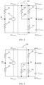
- FIG. 2 is a schematic diagram of a circuit structure of a common mode current controller of an inverter in an implementation according to an embodiment of this application.
- a positive electrode of a direct current voltage source PV is denoted as PV positive
- a negative electrode is denoted as PV negative
- a circuit equivalent component of a direct current busbar capacitor includes a positive terminal part C positive of the direct current busbar capacitor, a negative terminal part C negative of the direct current busbar capacitor, a positive terminal part R3 of an intrinsic ground impedance part of the direct current busbar capacitor, and a negative terminal part R4 of the intrinsic ground impedance part of the direct current busbar capacitor.
- One end of the positive terminal part C positive of the direct current busbar capacitor is a positive terminal of the direct current busbar capacitor, the positive terminal of the direct current busbar capacitor is connected to the positive terminal part R3 of the intrinsic ground impedance part of the direct current busbar capacitor, the other end is a midpoint of the direct current busbar capacitor, and a midpoint-to-ground voltage of the direct current busbar capacitor is denoted as BUSN.
- One end of the negative terminal part C negative of the direct current busbar capacitor is a negative terminal of the direct current busbar capacitor, the negative terminal of the direct current busbar capacitor is connected to the negative terminal part R4 of the intrinsic ground impedance part of the direct current busbar capacitor, and the other end is the midpoint of the direct current busbar capacitor.
- each of the positive terminal part R3 of the intrinsic ground impedance part of the direct current busbar capacitor and the negative terminal part R4 of the intrinsic ground impedance part of the direct current busbar capacitor is grounded.
- the positive electrode and the negative electrode of the direct current voltage source PV are respectively connected to the positive terminal part C positive of the direct current busbar capacitor and the negative terminal part C negative of the direct current busbar capacitor. Therefore, one end of each of the positive terminal-to-ground impedance circuit R1 of the direct current voltage source PV and the positive terminal part R3 of the intrinsic ground impedance part of the direct current busbar capacitor is grounded, and the other end is connected to the positive electrode of the direct current voltage source PV, to form a parallel connection relationship.
- each of the negative terminal-to-ground impedance circuit R2 of the direct current voltage source PV and the negative terminal part R4 of the intrinsic ground impedance part of the direct current busbar capacitor is grounded, and the other end is connected to the negative electrode of the direct current voltage source PV, to form a parallel connection relationship.
- a common mode current controller 200 includes an impedance correction circuit 202 and a switch 204.
- One end of the impedance correction circuit 202 is connected to the positive electrode PV positive of the direct current voltage source PV, the other end is connected to one end of the switch 204, and the other end of the switch 204 is grounded.
- R 1 represents a magnitude of the positive terminal-to-ground impedance circuit R1 of the direct current voltage source PV
- R 3 represents a magnitude of the positive terminal part R3 of the intrinsic ground impedance part of the direct current busbar capacitor
- R 202 represents a magnitude of the impedance correction circuit 202. Therefore, the switch 204 is closed, to introduce the impedance correction circuit 202 and reduce a magnitude of the positive terminal-to-ground equivalent impedance RES positive , of the direct current busbar capacitor, and the magnitude of the impedance correction circuit 202 is adjusted, to adjust the magnitude of the positive terminal-to-ground equivalent impedance RES positive , of the direct current busbar capacitor.
- the magnitude of the positive terminal-to-ground equivalent impedance RES positive , of the direct current busbar capacitor is adjusted, to adjust impedance matching between the positive terminal-to-ground equivalent impedance RES positive of the direct current busbar capacitor and negative terminal-to-ground equivalent impedance of the direct current busbar capacitor, so that the positive terminal-to-ground equivalent impedance RES positive of the direct current busbar capacitor can match the negative terminal-to-ground equivalent impedance of the direct current busbar capacitor, to pre-control a magnitude of a common mode current generated when the inverter is grid-tied, in other words, pre-control a magnitude of a common mode impulse current (leakage current).
- the negative terminal-to-ground equivalent impedance of the direct current busbar capacitor needs to be understood as a magnitude of equivalent impedance of a parallel connection of the negative terminal-to-ground impedance circuit R2 of the direct current voltage source PV and the negative terminal part R4 of the intrinsic ground impedance part of the direct current busbar capacitor.
- the positive terminal-to-ground equivalent impedance RES positive , of the direct current busbar capacitor is equivalent to a magnitude of equivalent impedance of a parallel connection of the positive terminal-to-ground impedance circuit R1 of the direct current voltage source PV and the positive terminal part R3 of the intrinsic ground impedance part of the direct current busbar capacitor.
- the positive terminal-to-ground equivalent impedance RES positive , of the direct current busbar capacitor or the negative terminal-to-ground equivalent impedance of the direct current busbar capacitor changes, resulting in impedance mismatching.
- the switch 214 is closed, to reduce the magnitude of the positive terminal-to-ground equivalent impedance RES positive , of the direct current busbar capacitor, so as to effectively reduce an upward floating degree of the BUSN potential, and help restore impedance matching and control a magnitude of the common mode impulse current.
- the common mode current controller 200 includes the switch 204 and the impedance correction circuit 202.
- One end of the impedance correction circuit 202 is grounded, the other end of the impedance correction circuit 202 is connected to one end of the switch 204, and the other end of the switch 204 is connected to the positive terminal of the direct current busbar capacitor, so that the common mode current controller 200 and the positive terminal part of the intrinsic ground impedance part of the direct current busbar capacitor are connected in parallel between the positive terminal of the direct current busbar capacitor and the ground.
- the common mode current controller 200 is configured to: when the midpoint-to-ground voltage BUSN of the direct current busbar capacitor is greater than the first threshold, close the switch 204 to adjust impedance matching between the positive terminal-to-ground equivalent impedance of the direct current busbar capacitor and the negative terminal-to-ground equivalent impedance of the direct current busbar capacitor, so that the inverter can pre-control the magnitude of the common mode current generated when the inverter is grid-tied.
- introduction of the impedance correction circuit 202 and adjustment of impedance matching are implemented based on the midpoint-to-ground voltage BUSN of the direct current busbar capacitor, so that the magnitude of the common mode current generated when the inverter is grid-tied can be pre-controlled before the grid-tied switch of the inverter is closed, to help reduce a degree of complexity of a system design and reduce costs of the system design.
- the threshold or the first threshold may be preset, or may be set based on a corresponding inverter type and a parameter, or may be adjusted based on a corresponding state of a power grid and a use scenario. These may be adjusted and improved based on a specific application environment, and are not specifically limited herein.
- the magnitude of the impedance correction circuit 202 may be preset, or may be set based on a corresponding inverter type and a parameter, or may be adjusted based on a corresponding state of a power grid and a use scenario. These may be adjusted and improved based on a specific application environment, and are not specifically limited herein.
- a proper technical means may be used for a closing/opening mechanism of the switch 204 and a specific structure of the switch 204.
- conduction or breaking of a circuit may be controlled by using a controllable electronic component, including but not limited to a thyristor, a transistor, a field effect transistor, a silicon controlled thyristor, and a relay. These may be adjusted and improved based on a specific application environment, and are not specifically limited herein.
- the midpoint-to-ground voltage BUSN of the direct current busbar capacitor may be obtained through direct measurement, for example, may be obtained by using a voltage sensor; or may be obtained through indirect measurement, for example, may be determined based on the positive terminal voltage BUS positive and a negative terminal voltage BUS negative of the direct current busbar capacitor of the inverter. For example, the positive terminal-to-ground voltage BUS positive and the negative terminal-to-ground voltage BUS negative of the direct current busbar capacitor 106 are measured, and then a sum of BUS positive and BUS negative is divided by two.
- an impedance value of the impedance correction circuit 202 is adjustable, and the impedance value R 202 of the impedance correction circuit 202 is adjusted, so that a positive busbar and a negative busbar of the inverter have symmetric impedance to ground.
- the common mode current controller 200 is a part of a grid-tied inverter, and the grid-tied inverter includes a direct current-direct current DC-DC converter and a direct current-alternating current DC-AC converter.
- the common mode current controller 210 is between the DC-DC converter and the DC-AC converter.
- the common mode current controller 200 is further configured to control to release a residual charge of a Y capacitor at a terminal of the inverter.
- the Y capacitor at the terminal is a capacitor on an AC side of the inverter.
- each grid-tied inverter and the common mode current controller 200 include a same device and similar structures, to have an improved capability of resisting impact of a common mode current generated at a grid-tied instant of the photovoltaic power generation system.
- the common mode current controller 200 is part of the photovoltaic power generation system, the photovoltaic power generation system includes the grid-tied inverter, the grid-tied inverter includes the common mode current controller 200, and the first threshold is set based on a state of a power grid to which the grid-tied inverter is tied.
- FIG. 3 is a schematic diagram of a circuit structure of a common mode current controller of an inverter in another implementation according to an embodiment of this application.
- a positive electrode of a direct current voltage source PV is denoted as PV positive
- a negative electrode is denoted as PV negative
- a circuit equivalent component of a direct current busbar capacitor includes a positive terminal part C positive of the direct current busbar capacitor, a negative terminal part C negative of the direct current busbar capacitor, a positive terminal part R3 of an intrinsic ground impedance part of the direct current busbar capacitor, and a negative terminal part R4 of the intrinsic ground impedance part of the direct current busbar capacitor.
- One end of the positive terminal part C positive of the direct current busbar capacitor is a positive terminal of the direct current busbar capacitor, the positive terminal of the direct current busbar capacitor is connected to the positive terminal part R3 of the intrinsic ground impedance part of the direct current busbar capacitor, the other end is a midpoint of the direct current busbar capacitor, and a midpoint-to-ground voltage of the direct current busbar capacitor is denoted as BUSN.
- One end of the negative terminal part C negative of the direct current busbar capacitor is a negative terminal of the direct current busbar capacitor, the negative terminal of the direct current busbar capacitor is connected to the negative terminal part R4 of the intrinsic ground impedance part of the direct current busbar capacitor, and the other end is the midpoint of the direct current busbar capacitor.
- each of the positive terminal part R3 of the intrinsic ground impedance part of the direct current busbar capacitor and the negative terminal part R4 of the intrinsic ground impedance part of the direct current busbar capacitor is grounded.
- the positive electrode and the negative electrode of the direct current voltage source PV are respectively connected to the positive terminal part C positive of the direct current busbar capacitor and the negative terminal part C negative of the direct current busbar capacitor. Therefore, one end of each of the positive terminal-to-ground impedance circuit R1 of the direct current voltage source PV and the positive terminal part R3 of the intrinsic ground impedance part of the direct current busbar capacitor is grounded, and the other end is connected to the positive electrode of the direct current voltage source PV, to form a parallel connection relationship.
- each of the negative terminal-to-ground impedance circuit R2 of the direct current voltage source PV and the negative terminal part R4 of the intrinsic ground impedance part of the direct current busbar capacitor is grounded, and the other end is connected to the negative electrode of the direct current voltage source PV, to form a parallel connection relationship.
- a common mode current controller 300 includes an impedance correction circuit 302 and a switch 304.
- One end of the impedance correction circuit 302 is connected to the negative electrode PV negative of the direct current voltage source PV, the other end is connected to one end of the switch 304, and the other end of the switch 304 is grounded.
- R 2 represents a magnitude of the negative terminal-to-ground impedance circuit R2 of the direct current voltage source PV
- R 4 represents a magnitude of the negative terminal part R4 of the intrinsic ground impedance part of the direct current busbar capacitor
- R 302 represents a magnitude of the impedance correction circuit 302. Therefore, the switch 304 is closed, to introduce the impedance correction circuit 302 and reduce a magnitude of the negative terminal-to-ground equivalent impedance RES negative of the direct current busbar capacitor, and the magnitude of the impedance correction circuit 302 is adjusted, to adjust the magnitude of the negative terminal-to-ground equivalent impedance RES negative of the direct current busbar capacitor.
- the magnitude of the negative terminal-to-ground equivalent impedance RES negative of the direct current busbar capacitor is adjusted, to adjust impedance matching between positive terminal-to-ground equivalent impedance of the direct current busbar capacitor and the negative terminal-to-ground equivalent impedance RES negative of the direct current busbar capacitor, so that the positive terminal-to-ground equivalent impedance of the direct current busbar capacitor can match the negative terminal-to-ground equivalent impedance RES negative of the direct current busbar capacitor, to pre-control a magnitude of a common mode current generated when the inverter is grid-tied, in other words, pre-control a magnitude of a common mode impulse current (leakage current).
- the positive terminal-to-ground equivalent impedance of the direct current busbar capacitor needs to be understood as a magnitude of equivalent impedance of a parallel connection of the positive terminal-to-ground impedance circuit R1 of the direct current voltage source PV and the positive terminal part R3 of the intrinsic ground impedance part of the direct current busbar capacitor.
- the negative terminal-to-ground equivalent impedance RES negative of the direct current busbar capacitor is equivalent to a magnitude of equivalent impedance of a parallel connection of the negative terminal-to-ground impedance circuit R2 of the direct current voltage source PV and the negative terminal part R4 of the intrinsic ground impedance part of the direct current busbar capacitor.
- the positive terminal-to-ground equivalent impedance of the direct current busbar capacitor or the negative terminal-to-ground equivalent impedance RES negative of the direct current busbar capacitor changes, resulting in impedance mismatching.
- the switch 304 is closed, to reduce the magnitude of the negative terminal-to-ground equivalent impedance RES negative of the direct current busbar capacitor, so as to effectively reduce a downward floating degree of the BUSN potential, and help restore impedance matching and control a magnitude of the common mode impulse current.
- the common mode current controller 300 includes the switch 304 and the impedance correction circuit 302. One end of the impedance correction circuit 302 is grounded, the other end of the impedance correction circuit 302 is connected to one end of the switch 304, and the other end of the switch 304 is connected to the negative terminal of the direct current busbar capacitor, so that the common mode current controller 300 and the negative terminal part of the intrinsic ground impedance part of the direct current busbar capacitor are connected in parallel between the negative terminal of the direct current busbar capacitor and the ground.
- the common mode current controller 300 is configured to: when the midpoint-to-ground voltage of the direct current busbar capacitor is less than the first threshold, close the switch 304 to adjust impedance matching between the positive terminal-to-ground equivalent impedance of the direct current busbar capacitor and the negative terminal-to-ground equivalent impedance of the direct current busbar capacitor, so that the inverter can pre-control the magnitude of the common mode current generated when the inverter is grid-tied.
- introduction of the impedance correction circuit 302 and adjustment of impedance matching are implemented based on the midpoint-to-ground voltage BUSN of the direct current busbar capacitor, so that the magnitude of the common mode current generated when the inverter is grid-tied can be pre-controlled before the grid-tied switch of the inverter is closed, to help reduce a degree of complexity of a system design and reduce costs of the system design.
- the threshold or the first threshold may be preset, or may be set based on a corresponding inverter type and a parameter, or may be adjusted based on a corresponding state of a power grid and a use scenario. These may be adjusted and improved based on a specific application environment, and are not specifically limited herein.
- the magnitude of the impedance correction circuit 302 may be preset, or may be set based on a corresponding inverter type and a parameter, or may be adjusted based on a corresponding state of a power grid and a use scenario. These may be adjusted and improved based on a specific application environment, and are not specifically limited herein.
- a proper technical means may be used for a closing/opening mechanism of the switch 304 and a specific structure of the switch 304.
- conduction or breaking of a circuit may be controlled by using a controllable electronic component, including but not limited to a thyristor, a transistor, a field effect transistor, a silicon controlled thyristor, and a relay. These may be adjusted and improved based on a specific application environment, and are not specifically limited herein.
- the midpoint-to-ground voltage BUSN of the direct current busbar capacitor may be obtained through direct measurement, for example, may be obtained by using a voltage sensor; or may be obtained through indirect measurement, for example, may be determined based on the positive terminal voltage BUS positive and a negative terminal voltage BUS negative of the direct current busbar capacitor of the inverter. For example, the positive terminal-to-ground voltage BUS positive and the negative terminal-to-ground voltage BUS negative of the direct current busbar capacitor 106 are measured, and then a sum of BUS positive and BUS negative is divided by two.
- an impedance value of the impedance correction circuit 302 is adjustable, and the impedance value R 212 of the impedance correction circuit 302 is adjusted, so that a positive busbar and a negative busbar of the inverter have symmetric impedance to ground.
- the common mode current controller 300 is a part of the grid-tied inverter, and the grid-tied inverter includes a direct current-direct current DC-DC converter and a direct current-alternating current DC-AC converter.
- the common mode current controller 300 is between the DC-DC converter and the DC-AC converter.
- the common mode current controller 300 is further configured to control to release a residual charge of a Y capacitor at a terminal of the inverter.
- the Y capacitor at the terminal is a capacitor on an AC side of the inverter.
- each grid-tied inverter and the common mode current controller 300 include a same device and similar structures, to have an improved capability of resisting impact of a common mode current generated at a grid-tied instant of the photovoltaic power generation system.
- the common mode current controller 300 is part of the photovoltaic power generation system, the photovoltaic power generation system includes the grid-tied inverter, the grid-tied inverter includes the common mode current controller 300, and the first threshold is set based on a state of a power grid to which the grid-tied inverter is tied.
- FIG. 4 is a schematic diagram of a circuit structure of a common mode current controller of an inverter in another implementation according to an embodiment of this application.
- a positive electrode of a direct current voltage source PV is denoted as PV positive
- a negative electrode is denoted as PV negative
- a circuit equivalent component of a direct current busbar capacitor includes a positive terminal part C positive of the direct current busbar capacitor, a negative terminal part C negative of the direct current busbar capacitor, a positive terminal part R3 of an intrinsic ground impedance part of the direct current busbar capacitor, and a negative terminal part R4 of the intrinsic ground impedance part of the direct current busbar capacitor.
- One end of the positive terminal part C positive of the direct current busbar capacitor is a positive terminal of the direct current busbar capacitor, the positive terminal of the direct current busbar capacitor is connected to the positive terminal part R3 of the intrinsic ground impedance part of the direct current busbar capacitor, the other end is a midpoint of the direct current busbar capacitor, and a midpoint-to-ground voltage of the direct current busbar capacitor is denoted as BUSN.
- One end of the negative terminal part C negative of the direct current busbar capacitor is a negative terminal of the direct current busbar capacitor, the negative terminal of the direct current busbar capacitor is connected to the negative terminal part R4 of the intrinsic ground impedance part of the direct current busbar capacitor, and the other end is the midpoint of the direct current busbar capacitor.
- each of the positive terminal part R3 of the intrinsic ground impedance part of the direct current busbar capacitor and the negative terminal part R4 of the intrinsic ground impedance part of the direct current busbar capacitor is grounded.
- the positive electrode and the negative electrode of the direct current voltage source PV are respectively connected to the positive terminal part C positive of the direct current busbar capacitor and the negative terminal part C negative of the direct current busbar capacitor. Therefore, one end of each of the positive terminal-to-ground impedance circuit R1 of the direct current voltage source PV and the positive terminal part R3 of the intrinsic ground impedance part of the direct current busbar capacitor is grounded, and the other end is connected to the positive electrode of the direct current voltage source PV, to form a parallel connection relationship.
- each of the negative terminal-to-ground impedance circuit R2 of the direct current voltage source PV and the negative terminal part R4 of the intrinsic ground impedance part of the direct current busbar capacitor is grounded, and the other end is connected to the negative electrode of the direct current voltage source PV, to form a parallel connection relationship.
- a common mode current controller 400 includes a first impedance correction circuit 402, a first switch 404, a second impedance correction circuit 406, and a second switch 408.
- One end of the first impedance correction circuit 402 is connected to the positive electrode PV positive , of the direct current voltage source PV, the other end is connected to one end of the first switch 404, and the other end of the first switch 404 is grounded.
- R 1 represents a magnitude of the positive terminal-to-ground impedance circuit R1 of the direct current voltage source PV
- R 3 represents a magnitude of the positive terminal part R3 of the intrinsic ground impedance part of the direct current busbar capacitor
- R 402 represents a magnitude of the first impedance correction circuit 402. Therefore, the first switch 404 is closed, to introduce the first impedance correction circuit 402 and reduce a magnitude of the positive terminal-to-ground equivalent impedance RES positive of the direct current busbar capacitor, and the magnitude of the first impedance correction circuit 402 is adjusted, to adjust the magnitude of the positive terminal-to-ground equivalent impedance RES positive , of the direct current busbar capacitor.
- the magnitude of the positive terminal-to-ground equivalent impedance RES positive , of the direct current busbar capacitor is adjusted, to adjust impedance matching between the positive terminal-to-ground equivalent impedance RES positive , of the direct current busbar capacitor and negative terminal-to-ground equivalent impedance of the direct current busbar capacitor, so that the positive terminal-to-ground equivalent impedance RES positive , of the direct current busbar capacitor can match the negative terminal-to-ground equivalent impedance of the direct current busbar capacitor, to pre-control a magnitude of a common mode current generated when the inverter is grid-tied, in other words, pre-control a magnitude of a common mode impulse current (leakage current).
- the negative terminal-to-ground equivalent impedance of the direct current busbar capacitor needs to be understood as a magnitude of equivalent impedance of a parallel connection of the negative terminal-to-ground impedance circuit R2 of the direct current voltage source PV and the negative terminal part R4 of the intrinsic ground impedance part of the direct current busbar capacitor.
- the positive terminal-to-ground equivalent impedance RES positive , of the direct current busbar capacitor is equivalent to a magnitude of equivalent impedance of a parallel connection of the positive terminal-to-ground impedance circuit R1 of the direct current voltage source PV and the positive terminal part R3 of the intrinsic ground impedance part of the direct current busbar capacitor. Affected by a change in an environmental factor such as a temperature and component aging, the positive terminal-to-ground equivalent impedance RES positive , of the direct current busbar capacitor or the negative terminal-to-ground equivalent impedance of the direct current busbar capacitor changes, resulting in impedance mismatching.
- the switch 404 is closed, to reduce the magnitude of the positive terminal-to-ground equivalent impedance RES positive , of the direct current busbar capacitor, so as to effectively reduce an upward floating degree of the BUSN potential, and help restore impedance matching and control a magnitude of the common mode impulse current.
- One end of the second impedance correction circuit 406 is connected to the negative electrode PV negative of the direct current voltage source PV, the other end is connected to one end of the second switch 408, and the other end of the second switch 408 is grounded. Therefore, when the second switch 408 is closed, one end of the second impedance correction circuit 406 is grounded, and the other end is connected to the negative electrode PV negative of the direct current voltage source PV, so that that the negative terminal-to-ground impedance circuit R2 of the direct current voltage source PV and the negative terminal part R4 of the intrinsic ground impedance part of the direct current busbar capacitor are connected in parallel between the negative terminal of the direct current busbar capacitor and a grounding (PE) node.
- PE grounding
- R 2 represents a magnitude of the negative terminal-to-ground impedance circuit R2 of the direct current voltage source PV
- R 4 represents a magnitude of the negative terminal part R4 of the intrinsic ground impedance part of the direct current busbar capacitor
- R 406 represents a magnitude of the second impedance correction circuit 406. Therefore, the second switch 408 is closed, to introduce the second impedance correction circuit 406 and reduce a magnitude of the negative terminal-to-ground equivalent impedance RES negative of the direct current busbar capacitor, and the magnitude of the second impedance correction circuit 406 is adjusted, to adjust the magnitude of the negative terminal-to-ground equivalent impedance RES negative of the direct current busbar capacitor.
- the magnitude of the negative terminal-to-ground equivalent impedance RES negative of the direct current busbar capacitor is adjusted, to adjust impedance matching between the positive terminal-to-ground equivalent impedance of the direct current busbar capacitor and the negative terminal-to-ground equivalent impedance RES negative of the direct current busbar capacitor, so that the positive terminal-to-ground equivalent impedance of the direct current busbar capacitor can match the negative terminal-to-ground equivalent impedance RES negative of the direct current busbar capacitor, to pre-control a magnitude of a common mode current generated when the inverter is grid-tied, in other words, pre-control a magnitude of a common mode impulse current (leakage current).
- the positive terminal-to-ground equivalent impedance of the direct current busbar capacitor needs to be understood as a magnitude of equivalent impedance of a parallel connection of the positive terminal-to-ground impedance circuit R1 of the direct current voltage source PV and the positive terminal part R3 of the intrinsic ground impedance part of the direct current busbar capacitor.
- the negative terminal-to-ground equivalent impedance RES negative of the direct current busbar capacitor is equivalent to a magnitude of equivalent impedance of a parallel connection of the negative terminal-to-ground impedance circuit R2 of the direct current voltage source PV and the negative terminal part R4 of the intrinsic ground impedance part of the direct current busbar capacitor.
- the positive terminal-to-ground equivalent impedance of the direct current busbar capacitor or the negative terminal-to-ground equivalent impedance RES negative of the direct current busbar capacitor changes, resulting in impedance mismatching.
- the positive terminal voltage BUS positive of the direct current busbar capacitor or the negative terminal voltage BUS negative of the direct current busbar capacitor fluctuate greatly, and the BUSN potential is not zero.
- the grid-tied switch of the inverter is closed, large impact of the common mode current is generated.
- a specific threshold which may be identified as a second threshold
- the second switch 408 is closed, to reduce the magnitude of the negative terminal-to-ground equivalent impedance RES negative of the direct current busbar capacitor, so as to effectively reduce the downward floating degree of the BUSN potential, and help restore impedance matching and control the magnitude of the common mode impulse current.
- the common mode current controller 400 includes: the first switch 404, where one end of the first switch 404 is connected to the positive terminal of the direct current busbar capacitor; the second switch 408, where one end of the second switch 408 is connected to the negative terminal of the direct current busbar capacitor; the first impedance correction circuit 402, where one end of the first impedance correction circuit 402 is grounded, and the other end of the first impedance correction circuit 402 is connected to the other end of the first switch 404; and the second impedance correction circuit 406, where one end of the second impedance correction circuit 406 is grounded, and the other end of the second impedance correction circuit 406 is connected to the other end of the second switch 408.
- the common mode current controller 400 is configured to: when the midpoint-to-ground voltage BUSN of the direct current busbar capacitor is greater than the first threshold, close the first switch 404, and open the second switch 408, so that the first impedance correction circuit 402 and the positive terminal part of the intrinsic ground impedance part of the direct current busbar capacitor are connected in parallel between the positive terminal of the direct current busbar capacitor and the ground, to reduce the magnitude of the positive terminal-to-ground equivalent impedance of the direct current busbar capacitor.
- the common mode current controller 400 is configured to: when the midpoint-to-ground voltage BUSN of the direct current busbar capacitor is less than the second threshold, close the second switch 408, and open the first switch 404, so that the second impedance correction circuit 406 and the negative terminal part of the intrinsic ground impedance part of the direct current busbar capacitor are connected in parallel between the negative terminal of the direct current busbar capacitor and the ground, to reduce the magnitude of the negative terminal-to-ground equivalent impedance of the direct current busbar capacitor.
- the common mode current controller 400 adjusts impedance matching between the positive terminal-to-ground equivalent impedance of the direct current busbar capacitor and the negative terminal-to-ground equivalent impedance of the direct current busbar capacitor, so that the inverter can pre-control the magnitude of the common mode current generated when the inverter is grid-tied.
- introduction of the first impedance correction circuit 402 or the second impedance correction circuit 406 and adjustment of impedance matching are implemented based on the midpoint-to-ground voltage BUSN of the direct current busbar capacitor, so that the magnitude of the common mode current generated when the inverter is grid-tied can be pre-controlled before the grid-tied switch of the inverter is closed, to help reduce a degree of complexity of a system design and reduce costs of the system design.
- the first threshold or the second threshold may be preset, or may be set based on a corresponding inverter type and a parameter, or may be adjusted based on a corresponding state of a power grid and a use scenario. These may be adjusted and improved based on a specific application environment, and are not specifically limited herein.
- the size of the first impedance correction circuit 402 or the second impedance correction circuit 406 may be preset, or may be set based on a corresponding inverter type and a parameter, or may be adjusted based on a corresponding state of a power grid and a use scenario. These may be adjusted and improved based on a specific application environment, and are not specifically limited herein.
- a proper technical means may be used for a closing/opening mechanism of the first switch 404 or the second switch 408 and a specific structure of the first switch 404 or the second switch 408.
- conduction or breaking of a circuit may be controlled by using a controllable electronic component, including but not limited to a thyristor, a transistor, a field effect transistor, a silicon controlled thyristor, and a relay. These may be adjusted and improved based on a specific application environment, and are not specifically limited herein.
- the midpoint-to-ground voltage BUSN of the direct current busbar capacitor may be obtained through direct measurement, for example, may be obtained by using a voltage sensor; or may be obtained through indirect measurement, for example, may be determined based on the positive terminal voltage BUS positive and a negative terminal voltage BUS negative of the direct current busbar capacitor of the inverter. For example, the positive terminal-to-ground voltage BUS positive and the negative terminal-to-ground voltage BUS negative of the direct current busbar capacitor 106 are measured, and then a sum of BUS positive and BUS negative is divided by two.
- an impedance value of the first impedance correction circuit 402 and an impedance value of the second impedance correction circuit 406 are both adjustable, and the impedance value of the first impedance correction circuit 402 and the impedance value of the second impedance correction circuit 406 are adjusted, so that a positive busbar and a negative busbar of the inverter have symmetric impedance to ground.
- the common mode current controller 400 is a part of the grid-tied inverter, and the grid-tied inverter includes a direct current-direct current DC-DC converter and a direct current-alternating current DC-AC converter.
- the common mode current controller 400 is between the DC-DC converter and the DC-AC converter.
- the common mode current controller 400 is further configured to control to release a residual charge of a Y capacitor at a terminal of the inverter.
- the Y capacitor at the terminal is a capacitor on an AC side of the inverter.
- each grid-tied inverter and the common mode current controller 400 include a same device and similar structures, to have an improved capability of resisting impact of a common mode current generated at a grid-tied instant of the photovoltaic power generation system.
- the common mode current controller 400 is part of the photovoltaic power generation system, the photovoltaic power generation system includes the grid-tied inverter, the grid-tied inverter includes the common mode current controller 400, and the first threshold and the second threshold are set based on a state of a power grid to which the grid-tied inverter is tied.
- FIG. 5 is a schematic diagram of a circuit structure of a common mode current controller of an inverter in another implementation according to an embodiment of this application.
- a positive electrode of a direct current voltage source PV is denoted as PV positive
- a negative electrode is denoted as PV negative
- a circuit equivalent component of a direct current busbar capacitor includes a positive terminal part C positive of the direct current busbar capacitor, a negative terminal part C negative of the direct current busbar capacitor, a positive terminal part R3 of an intrinsic ground impedance part of the direct current busbar capacitor, and a negative terminal part R4 of the intrinsic ground impedance part of the direct current busbar capacitor.
- One end of the positive terminal part C positive of the direct current busbar capacitor is a positive terminal of the direct current busbar capacitor, the positive terminal of the direct current busbar capacitor is connected to the positive terminal part R3 of the intrinsic ground impedance part of the direct current busbar capacitor, the other end is a midpoint of the direct current busbar capacitor, and a midpoint-to-ground voltage of the direct current busbar capacitor is denoted as BUSN.
- One end of the negative terminal part C negative of the direct current busbar capacitor is a negative terminal of the direct current busbar capacitor, the negative terminal of the direct current busbar capacitor is connected to the negative terminal part R4 of the intrinsic ground impedance part of the direct current busbar capacitor, and the other end is the midpoint of the direct current busbar capacitor.
- each of the positive terminal part R3 of the intrinsic ground impedance part of the direct current busbar capacitor and the negative terminal part R4 of the intrinsic ground impedance part of the direct current busbar capacitor is grounded.
- the positive electrode and the negative electrode of the direct current voltage source PV are respectively connected to the positive terminal part C positive of the direct current busbar capacitor and the negative terminal part C negative of the direct current busbar capacitor. Therefore, one end of each of the positive terminal-to-ground impedance circuit R1 of the direct current voltage source PV and the positive terminal part R3 of the intrinsic ground impedance part of the direct current busbar capacitor is grounded, and the other end is connected to the positive electrode of the direct current voltage source PV, to form a parallel connection relationship.
- each of the negative terminal-to-ground impedance circuit R2 of the direct current voltage source PV and the negative terminal part R4 of the intrinsic ground impedance part of the direct current busbar capacitor is grounded, and the other end is connected to the negative electrode of the direct current voltage source PV, to form a parallel connection relationship.
- a common mode current controller 500 includes a first impedance correction circuit 502, a second impedance correction circuit 504, and a single-pole triple-throw switch (Single Pole Triple Throw, SP3T) 506.
- the single-pole triple-throw switch 506 includes one movable end and three movable ends, the movable end is grounded, and the three movable ends respectively correspond to three connection states.
- One end of the first impedance correction circuit 502 is connected to the positive electrode PV positive , of the direct current voltage source PV, and the other end is connected to the first movable end of the single-pole triple-throw switch 506.
- R 1 represents a magnitude of the positive terminal-to-ground impedance circuit R1 of the direct current voltage source PV
- R 3 represents a magnitude of the positive terminal part R3 of the intrinsic ground impedance part of the direct current busbar capacitor
- R 502 represents a magnitude of the first impedance correction circuit 502. Therefore, the single-pole triple-throw switch 506 is switched to the connection state of the first movable end, to introduce the first impedance correction circuit 502 and reduce a magnitude of the positive terminal-to-ground equivalent impedance RES positive , of the direct current busbar capacitor, and the magnitude of the first impedance correction circuit 502 is adjusted, to adjust the magnitude of the positive terminal-to-ground equivalent impedance RES positive , of the direct current busbar capacitor.
- the magnitude of the positive terminal-to-ground equivalent impedance RES positive , of the direct current busbar capacitor is adjusted, to adjust impedance matching between the positive terminal-to-ground equivalent impedance RES positive , of the direct current busbar capacitor and negative terminal-to-ground equivalent impedance of the direct current busbar capacitor, so that the positive terminal-to-ground equivalent impedance RES positive , of the direct current busbar capacitor can match the negative terminal-to-ground equivalent impedance of the direct current busbar capacitor, to pre-control a magnitude of a common mode current generated when the inverter is grid-tied, in other words, pre-control a magnitude of a common mode impulse current (leakage current).
- the negative terminal-to-ground equivalent impedance of the direct current busbar capacitor needs to be understood as a magnitude of equivalent impedance of a parallel connection of the negative terminal-to-ground impedance circuit R2 of the direct current voltage source PV and the negative terminal part R4 of the intrinsic ground impedance part of the direct current busbar capacitor.
- One end of the second impedance correction circuit 504 is connected to the negative electrode PV negative of the direct current voltage source PV, and the other end is connected to the second movable end of the single-pole triple-throw switch 506.
- the third movable end of the single-pole triple-throw switch 506 may correspond to a case in which the single-pole triple-throw switch 506 is connected to neither the first impedance correction circuit 502 nor the second impedance correction circuit 504, for example, is grounded.
- R 2 represents a magnitude of the negative terminal-to-ground impedance circuit R2 of the direct current voltage source PV
- R 4 represents a magnitude of the negative terminal part R4 of the intrinsic ground impedance part of the direct current busbar capacitor
- R 504 represents a magnitude of the second impedance correction circuit 504. Therefore, when the single-pole triple-throw switch 506 is switched to the connection state of the second movable end, the second impedance correction circuit 504 may be introduced, and the magnitude of the negative terminal-to-ground equivalent impedance RES negative of the direct current busbar capacitor may be reduced, and the magnitude of the second impedance correction circuit 504 is adjusted, to adjust the magnitude of the negative terminal-to-ground equivalent impedance RES negative of the direct current busbar capacitor.
- the magnitude of the negative terminal-to-ground equivalent impedance RES negative of the direct current busbar capacitor is adjusted, to adjust impedance matching between the positive terminal-to-ground equivalent impedance of the direct current busbar capacitor and the negative terminal-to-ground equivalent impedance RES negative of the direct current busbar capacitor, so that the positive terminal-to-ground equivalent impedance of the direct current busbar capacitor can match the negative terminal-to-ground equivalent impedance RES negative of the direct current busbar capacitor, to pre-control the magnitude of the common mode current generated when the inverter is grid-tied, in other words, pre-control a magnitude of a common mode impulse current (leakage current).
- the positive terminal-to-ground equivalent impedance of the direct current busbar capacitor needs to be understood as a magnitude of equivalent impedance of a parallel connection of the positive terminal-to-ground impedance circuit R1 of the direct current voltage source PV and the positive terminal part R3 of the intrinsic ground impedance part of the direct current busbar capacitor.
- the positive terminal-to-ground equivalent impedance RES positive of the direct current busbar capacitor or the negative terminal-to-ground equivalent impedance RES negative of the direct current busbar capacitor changes, resulting in impedance mismatching. Consequently, a positive terminal voltage BUS positive , of the direct current busbar capacitor or a negative terminal voltage BUS negative of the direct current busbar capacitor fluctuate greatly, and a BUSN potential is not zero. In this case, if a grid-tied switch of the inverter is closed, large impact of the common mode current is generated. Specifically, in the circuit structure of the common mode current controller of the inverter shown in FIG.
- the single-pole triple-throw switch 506 is switched to the connection state of the first movable end, to reduce the magnitude of the positive terminal-to-ground equivalent impedance RES positive of the direct current busbar capacitor, so as to effectively reduce an upward floating degree of the BUSN potential, and help restore impedance matching and control a magnitude of the common mode impulse current.
- the single-pole triple-throw switch 506 is switched to the connection state of the second movable end, to reduce the magnitude of the negative terminal-to-ground equivalent impedance RES negative of the direct current busbar capacitor, so as to effectively reduce a downward floating degree of the BUSN potential and control a magnitude of the common mode impulse current.
- the common mode current controller 500 includes: the single-pole triple-throw switch 506, where the non-movable end of the single-pole triple-throw switch 506 is grounded, and the movable ends of the single-pole triple-throw switch 506 include the first movable end, the second movable end, and the third movable end; the first impedance correction circuit 502, where one end of the first impedance correction circuit 502 is connected to the first movable end of the single-pole triple-throw switch 506, and the other end of the first impedance correction circuit 502 is connected to the positive terminal of the direct current busbar capacitor; and the second impedance correction circuit 504, where one end of the second impedance correction circuit 504 is connected to the second movable end of the single-pole triple-throw switch 506, and the other end of the second impedance correction circuit 504 is connected to the negative terminal of the direct current busbar capacitor.
- the common mode current controller 500 is configured to: when the midpoint-to-ground voltage BUSN of the direct current busbar capacitor is greater than the first threshold, switch the single-pole triple-throw switch 506 to the first movable end, so that the first impedance correction circuit 502 and the positive terminal part of the intrinsic ground impedance part of the direct current busbar capacitor are connected in parallel between the positive terminal of the direct current busbar capacitor and the ground, to reduce a magnitude of the positive terminal-to-ground equivalent impedance of the direct current busbar capacitor.
- the common mode current controller 500 is configured to: when the midpoint-to-ground voltage BUSN of the direct current busbar capacitor is less than the second threshold, switch the single-pole triple-throw switch 506 to the second movable end, so that the second impedance correction circuit 504 and a negative terminal part of the intrinsic ground impedance part of the direct current busbar capacitor are connected in parallel between the negative terminal of the direct current busbar capacitor and the ground, to reduce a magnitude of the negative terminal-to-ground equivalent impedance of the direct current busbar capacitor.
- the common mode current controller 500 adjusts impedance matching between the positive terminal-to-ground equivalent impedance of the direct current busbar capacitor and the negative terminal-to-ground equivalent impedance of the direct current busbar capacitor, so that the inverter can pre-control the magnitude of the common mode current generated when the inverter is grid-tied.
- introduction of the first impedance correction circuit 502 or the second impedance correction circuit 504 and adjustment of impedance matching are implemented based on the midpoint-to-ground voltage BUSN of the direct current busbar capacitor, so that the magnitude of the common mode current generated when the inverter is grid-tied can be pre-controlled before the grid-tied switch of the inverter is closed, to help reduce a degree of complexity of a system design and reduce costs of the system design.
- the first threshold or the second threshold may be preset, or may be set based on a corresponding inverter type and a parameter, or may be adjusted based on a corresponding state of a power grid and a use scenario. These may be adjusted and improved based on a specific application environment, and are not specifically limited herein.
- the magnitude of the first impedance correction circuit 502 or the second impedance correction circuit 504 may be preset, or may be set based on a corresponding inverter type and a parameter, or may be adjusted based on a corresponding state of a power grid and a use scenario. These may be adjusted and improved based on a specific application environment, and are not specifically limited herein.
- a proper technical means may be used for a connection state switching mechanism of the single-pole triple-throw switch 506 and a specific structure of the single-pole triple-throw switch 506.
- conduction or breaking of a circuit may be controlled by using a controllable electronic component, including but not limited to a thyristor, a transistor, a field effect transistor, a silicon controlled thyristor, and a relay. These may be adjusted and improved based on a specific application environment, and are not specifically limited herein.
- the midpoint-to-ground voltage BUSN of the direct current busbar capacitor may be obtained through direct measurement, for example, may be obtained by using a voltage sensor; or may be obtained through indirect measurement, for example, may be determined based on the positive terminal voltage BUS positive and a negative terminal voltage BUS negative of the direct current busbar capacitor of the inverter. For example, the positive terminal-to-ground voltage BUS positive and the negative terminal-to-ground voltage BUS negative of the direct current busbar capacitor 106 are measured, and then a sum of BUS positive and BUS negative is divided by two.
- an impedance value of the first impedance correction circuit 502 and an impedance value of the second impedance correction circuit 504 are both adjustable, and the impedance value of the first impedance correction circuit 502 and the impedance value of the second impedance correction circuit 504 are adjusted, so that a positive busbar and a negative busbar of the inverter have symmetric impedance to ground.
- the common mode current controller 500 is a part of the grid-tied inverter, and the grid-tied inverter includes a direct current-direct current DC-DC converter and a direct current-alternating current DC-AC converter.
- the common mode current controller 500 is between the DC-DC converter and the DC-AC converter.
- the common mode current controller 500 is further configured to control release of a residual charge of a Y capacitor at a terminal of the inverter.
- the Y capacitor at the terminal is a capacitor on an AC side of the inverter.
- each grid-tied inverter and the common mode current controller 500 include a same device and similar structures, to have an improved capability of resisting impact of a common mode current generated at a grid-tied instant of the photovoltaic power generation system.
- the common mode current controller 500 is part of the photovoltaic power generation system, the photovoltaic power generation system includes the grid-tied inverter, the grid-tied inverter includes the common mode current controller 500, and the first threshold and the second threshold are set based on a state of a power grid to which the grid-tied inverter is tied.
- FIG. 6 is a schematic diagram of a circuit structure of a common mode current controller of an inverter in another implementation according to an embodiment of this application.
- a positive electrode of a direct current voltage source PV is denoted as PV positive
- a negative electrode is denoted as PV negative
- a circuit equivalent component of a direct current busbar capacitor includes a positive terminal part C positive of the direct current busbar capacitor, a negative terminal part C negative of the direct current busbar capacitor, a positive terminal part R3 of an intrinsic ground impedance part of the direct current busbar capacitor, and a negative terminal part R4 of the intrinsic ground impedance part of the direct current busbar capacitor.
- One end of the positive terminal part C positive of the direct current busbar capacitor is a positive terminal of the direct current busbar capacitor, the positive terminal of the direct current busbar capacitor is connected to the positive terminal part R3 of the intrinsic ground impedance part of the direct current busbar capacitor, the other end is a midpoint of the direct current busbar capacitor, and a midpoint-to-ground voltage of the direct current busbar capacitor is denoted as BUSN.
- One end of the negative terminal part C negative of the direct current busbar capacitor is a negative terminal of the direct current busbar capacitor, the negative terminal of the direct current busbar capacitor is connected to the negative terminal part R4 of the intrinsic ground impedance part of the direct current busbar capacitor, and the other end is the midpoint of the direct current busbar capacitor.
- each of the positive terminal part R3 of the intrinsic ground impedance part of the direct current busbar capacitor and the negative terminal part R4 of the intrinsic ground impedance part of the direct current busbar capacitor is grounded.
- the positive electrode and the negative electrode of the direct current voltage source PV are respectively connected to the positive terminal part C positive of the direct current busbar capacitor and the negative terminal part C negative of the direct current busbar capacitor. Therefore, one end of each of the positive terminal-to-ground impedance circuit R1 of the direct current voltage source PV and the positive terminal part R3 of the intrinsic ground impedance part of the direct current busbar capacitor is grounded, and the other end is connected to the positive electrode of the direct current voltage source PV, to form a parallel connection relationship.
- each of the negative terminal-to-ground impedance circuit R2 of the direct current voltage source PV and the negative terminal part R4 of the intrinsic ground impedance part of the direct current busbar capacitor is grounded, and the other end is connected to the negative electrode of the direct current voltage source PV, to form a parallel connection relationship.
- a common mode current controller 600 includes an impedance correction circuit 602, a first switch 604, and a second switch 606. One end of the impedance correction circuit 602 is grounded, and the other end is connected to both the first switch 604 and the second switch 606.
- One end of the first switch 604 is connected to the impedance correction circuit 602, and the other end is connected to the positive electrode PV positive of the direct current voltage source PV
- One end of the second switch 606 is connected to the impedance correction circuit 602, and the other end is connected to the negative electrode PV negative of the direct current voltage source PV Therefore, when the first switch 604 is closed and the second switch 606 is opened, one end of the impedance correction circuit 602 is grounded, and the other end is connected to the positive electrode of the direct current voltage source PV, so that the positive terminal-to-ground impedance circuit R1 of the direct current voltage source PV and the positive terminal part R3 of the intrinsic ground impedance part of the direct current busbar capacitor are connected in parallel between the positive terminal of the direct current busbar capacitor and a grounding (PE) node.
- PE grounding
- R 1 represents a magnitude of the positive terminal-to-ground impedance circuit R1 of the direct current voltage source PV
- R 3 represents a magnitude of the positive terminal part R3 of the intrinsic ground impedance part of the direct current busbar capacitor
- R 602 represents a magnitude of the impedance correction circuit 602. Therefore, the first switch 604 is closed and the second switch 606 is opened, to introduce the impedance correction circuit 602 and reduce a magnitude of the positive terminal-to-ground equivalent impedance RES positive , of the direct current busbar capacitor, and the magnitude of the impedance correction circuit 602 is adjusted, to adjust the magnitude of the positive terminal-to-ground equivalent impedance RES positive of the direct current busbar capacitor.
- the magnitude of the positive terminal-to-ground equivalent impedance RES positive of the direct current busbar capacitor is adjusted, to adjust impedance matching between the positive terminal-to-ground equivalent impedance RES positive , of the direct current busbar capacitor and negative terminal-to-ground equivalent impedance of the direct current busbar capacitor, so that the positive terminal-to-ground equivalent impedance RES positive , of the direct current busbar capacitor can match the negative terminal-to-ground equivalent impedance of the direct current busbar capacitor, to pre-control a magnitude of a common mode current generated when the inverter is grid-tied, in other words, pre-control a magnitude of a common mode impulse current (leakage current).
- the negative terminal-to-ground equivalent impedance of the direct current busbar capacitor needs to be understood as a magnitude of equivalent impedance of a parallel connection of the negative terminal-to-ground impedance circuit R2 of the direct current voltage source PV and the negative terminal part R4 of the intrinsic ground impedance part of the direct current busbar capacitor.
- R 2 represents a magnitude of the negative terminal-to-ground impedance circuit R2 of the direct current voltage source PV
- R 4 represents a magnitude of the negative terminal part R4 of the intrinsic ground impedance part of the direct current busbar capacitor
- R 602 represents the magnitude of the impedance correction circuit 602. Therefore, the first switch 604 is opened and the second switch 606 is closed, to introduce the impedance correction circuit 602 and reduce a magnitude of the negative terminal-to-ground equivalent impedance RES negative of the direct current busbar capacitor, and the magnitude of the impedance correction circuit 602 is adjusted, to adjust the magnitude of the negative terminal-to-ground equivalent impedance RES negative of the direct current busbar capacitor.
- the magnitude of the negative terminal-to-ground equivalent impedance RES negative of the direct current busbar capacitor is adjusted, to adjust impedance matching between the positive terminal-to-ground equivalent impedance of the direct current busbar capacitor and the negative terminal-to-ground equivalent impedance RES negative of the direct current busbar capacitor, so that the positive terminal-to-ground equivalent impedance of the direct current busbar capacitor can match the negative terminal-to-ground equivalent impedance RES negative of the direct current busbar capacitor, to pre-control the magnitude of the common mode current generated when the inverter is grid-tied, in other words, pre-control the magnitude of the common mode impulse current (leakage current).
- the positive terminal-to-ground equivalent impedance of the direct current busbar capacitor needs to be understood as a magnitude of equivalent impedance of a parallel connection of the positive terminal-to-ground impedance circuit R1 of the direct current voltage source PV and the positive terminal part R3 of the intrinsic ground impedance part of the direct current busbar capacitor.
- the positive terminal-to-ground equivalent impedance RES positive of the direct current busbar capacitor or the negative terminal-to-ground equivalent impedance RES negative of the direct current busbar capacitor changes, resulting in impedance mismatching. Consequently, a positive terminal voltage BUS positive , of the direct current busbar capacitor or a negative terminal voltage BUS negative of the direct current busbar capacitor fluctuate greatly, and a BUSN potential is not zero. In this case, if a grid-tied switch of the inverter is closed, large impact of the common mode current is generated. In the circuit structure of the common mode current controller of the inverter shown in FIG.
- the first switch 604 is closed and the second switch 606 is opened, to reduce the magnitude of the positive terminal-to-ground equivalent impedance RES positive of the direct current busbar capacitor, so as to effectively reduce an upward floating degree of the BUSN potential, and help restore impedance matching and control a magnitude of the common mode impulse current.
- the first switch 604 is opened and the second switch 606 is closed, to reduce the magnitude of the negative terminal-to-ground equivalent impedance RES negative of the direct current busbar capacitor, so as to effectively reduce a downward floating degree of the BUSN potential and control the magnitude of the common mode impulse current.
- the common mode current controller 600 includes: the first switch 604, where one end of the first switch 604 is connected to the positive terminal of the direct current busbar capacitor; the second switch 606, where one end of the second switch 606 is connected to the negative terminal of the direct current busbar capacitor; and the impedance correction circuit 602, where one end of the impedance correction circuit 602 is grounded, and the other end of the impedance correction circuit 602 is connected to both the other end of the first switch 604 and the other end of the second switch 606.
- the common mode current controller 600 is configured to: when the midpoint-to-ground voltage BUSN of the direct current busbar capacitor is greater than the first threshold, close the first switch 604, and open the second switch 606, so that the impedance correction circuit 602 and the positive terminal part of the intrinsic ground impedance part of the direct current busbar capacitor are connected in parallel between the positive terminal of the direct current busbar capacitor and the ground, to reduce the magnitude of the positive terminal-to-ground equivalent impedance of the direct current busbar capacitor.
- the common mode current controller 600 is configured to: when the midpoint-to-ground voltage of the direct current busbar capacitor is less than the second threshold, close the second switch 606, and open the first switch 604, so that the impedance correction circuit and the negative terminal part of the intrinsic ground impedance part of the direct current busbar capacitor are connected in parallel between the negative terminal of the direct current busbar capacitor and the ground, to reduce the magnitude of the negative terminal-to-ground equivalent impedance of the direct current busbar capacitor.
- the common mode current controller 600 adjusts impedance matching between the positive terminal-to-ground equivalent impedance of the direct current busbar capacitor and the negative terminal-to-ground equivalent impedance of the direct current busbar capacitor, so that the inverter can pre-control the magnitude of the common mode current generated when the inverter is grid-tied.
- introduction of the impedance correction circuit 602 and adjustment of impedance matching are implemented based on the midpoint-to-ground voltage BUSN of the direct current busbar capacitor, so that the magnitude of the common mode current generated when the inverter is grid-tied can be pre-controlled before the grid-tied switch of the inverter is closed, to help reduce a degree of complexity of a system design and reduce costs of the system design.
- the first threshold or the second threshold may be preset, or may be set based on a corresponding inverter type and a parameter, or may be adjusted based on a corresponding state of a power grid and a use scenario. These may be adjusted and improved based on a specific application environment, and are not specifically limited herein.
- the magnitude of the impedance correction circuit 602 may be preset, or may be set based on a corresponding inverter type and a parameter, or may be adjusted based on a corresponding state of a power grid and a use scenario.
- the magnitude of the impedance correction circuit 602 may be separately set for adjusting the magnitude of the positive terminal-to-ground equivalent impedance RES positive , of the direct current busbar capacitor or the negative terminal-to-ground equivalent impedance RES negative of the direct current busbar capacitor. These may be adjusted and improved based on a specific application environment, and are not specifically limited herein.
- a proper technical means may be used for a closing/opening mechanism of the first switch 604 and the second switch 606 and a specific structure of the first switch 604 and the second switch 606.
- conduction or breaking of a circuit may be controlled by using a controllable electronic component, including but not limited to a thyristor, a transistor, a field effect transistor, a silicon controlled thyristor, and a relay. These may be adjusted and improved based on a specific application environment, and are not specifically limited herein.
- the midpoint-to-ground voltage BUSN of the direct current busbar capacitor may be obtained through direct measurement, for example, may be obtained by using a voltage sensor; or may be obtained through indirect measurement, for example, may be determined based on the positive terminal voltage BUS positive and a negative terminal voltage BUS negative of the direct current busbar capacitor of the inverter. For example, the positive terminal-to-ground voltage BUS positive and the negative terminal-to-ground voltage BUS negative of the direct current busbar capacitor 106 are measured, and then a sum of BUS positive and BUS negative is divided by two.
- an impedance value of the impedance correction circuit 602 is adjustable, the impedance value of the impedance correction circuit is set to a first impedance value when the midpoint-to-ground voltage is greater than the first threshold, the impedance value of the impedance correction circuit is set to a second impedance value when the midpoint-to-ground voltage is less than the second threshold, and the first impedance value and the second impedance value are set, so that a positive busbar and a negative busbar of the inverter have symmetric impedance to ground.
- the common mode current controller 600 is a part of the grid-tied inverter, and the grid-tied inverter includes a direct current-direct current DC-DC converter and a direct current-alternating current DC-AC converter.
- the common mode current controller 600 is between the DC-DC converter and the DC-AC converter.
- the common mode current controller 600 is further configured to control release of a residual charge of a Y capacitor at a terminal of the inverter.
- the Y capacitor at the terminal is a capacitor on an AC side of the inverter.
- each grid-tied inverter and the common mode current controller 600 include a same device and similar structures, to have an improved capability of resisting impact of a common mode current generated at a grid-tied instant of the photovoltaic power generation system.
- the common mode current controller 600 is part of the photovoltaic power generation system, the photovoltaic power generation system includes the grid-tied inverter, the grid-tied inverter includes the common mode current controller 600, and the first threshold and the second threshold are set based on a state of a power grid to which the grid-tied inverter is tied.
- FIG. 7 is a schematic flowchart of a common mode current control method for an inverter according to an embodiment of this application. As shown in FIG. 7 , the control method includes the following steps.
- Step S700 Obtain a midpoint-to-ground voltage of a direct current busbar capacitor of the inverter.
- the midpoint-to-ground voltage of the direct current busbar capacitor may be obtained through direct measurement, for example, may be obtained by using a voltage sensor; or may be obtained through indirect measurement, for example, may be determined based on a positive terminal voltage and a negative terminal voltage of the direct current busbar capacitor of the inverter. Specifically, the positive terminal voltage and the negative terminal voltage of the direct current busbar capacitor of the inverter may be separately sampled, and the midpoint-to-ground voltage is obtained based on the positive terminal voltage and the negative terminal voltage of the direct current busbar capacitor of the inverter.
- Step S702 Compare the midpoint-to-ground voltage and each of a first threshold and a second threshold.
- the first threshold or the second threshold may be preset, or may be set based on a corresponding inverter type and a parameter, or may be adjusted based on a corresponding state of a power grid and a use scenario.
- Step S704 Introduce a first impedance correction circuit when the midpoint-to-ground voltage is greater than the first threshold.
- One end of the first impedance correction circuit is grounded, and the first impedance correction circuit and a positive terminal part of an intrinsic ground impedance part of the direct current busbar capacitor are connected in parallel.
- the inverter receives a direct current input from a direct current voltage source.
- One end of the first impedance correction circuit is connected to a positive electrode of the direct current voltage source, the other end is connected to one end of a first switch, and the other end of the first switch is grounded. Therefore, when the first switch is closed, one end of the first impedance correction circuit is grounded, and the other end is connected to the positive electrode of the direct current voltage source, so that a positive terminal-to-ground impedance circuit of the direct current voltage source PV and the positive terminal part of the intrinsic ground impedance part of the direct current busbar capacitor are connected in parallel between a positive terminal of the direct current busbar capacitor and a grounding (PE) node.
- PE grounding
- the first switch When it is detected that the midpoint-to-ground voltage of the direct current busbar capacitor is greater than the first threshold, it indicates that a potential floats upward and goes beyond a normal range and a large common mode impulse current at a grid-tied instant may be generated.
- the first switch is closed, to reduce a magnitude of positive terminal-to-ground equivalent impedance of the direct current busbar capacitor, so as to effectively reduce an upward floating degree of the potential and control a magnitude of the common mode impulse current.
- Step S706 Introduce a second impedance correction circuit when the midpoint-to-ground voltage is less than the second threshold.
- One end of the second impedance correction circuit is grounded, and the second impedance correction circuit and a negative terminal part of the intrinsic ground impedance part of the direct current busbar capacitor are connected in parallel.
- the inverter receives the direct current input from the direct current voltage source.
- One end of the second impedance correction circuit is connected to a negative electrode of the direct current voltage source, the other end is connected to one end of a second switch, and the other end of the second switch is grounded. Therefore, when the second switch is closed, one end of the second impedance correction circuit is grounded, and the other end is connected to the negative electrode of the direct current voltage source, so that a negative terminal-to-ground impedance circuit of the direct current voltage source PV and the negative terminal part of the intrinsic ground impedance part of the direct current busbar capacitor are connected in parallel between the negative terminal of the direct current busbar capacitor and the grounding (PE) node.
- PE grounding
- the second switch When it is detected that the midpoint-to-ground voltage of the direct current busbar capacitor is less than the second threshold, it indicates that the potential floats downward and goes beyond the normal range and a large common mode impulse current at the grid-tied instant may be generated.
- the second switch is closed, to reduce a magnitude of negative terminal-to-ground equivalent impedance of the direct current busbar capacitor, so as to effectively reduce a downward floating degree of the potential and control a magnitude of the common mode impulse current.
- a device or an apparatus provided in specific embodiments of this application may include one or more processors (for example, a microprocessor, a controller, a digital signal processor (DSP), an application-specific integrated circuit (ASIC), or a field programmable gate array (FPGA)), and the processors process various computer-executable instructions, to control operation of the device or the apparatus.
- the device or the apparatus provided in specific embodiments of this application may include a system bus or a data transmission system in which various components are coupled together.
- the system bus may include any one of different bus structures or a combination of different bus structures, for example, a memory bus or a memory controller, a peripheral bus, a universal serial bus, and/or a processor or a local bus for which any of a plurality of bus architectures is used.
- the device or the apparatus provided in specific embodiments of this application may be independently provided, or may be a part of a system, or may be a part of another device or apparatus.
- Specific embodiments provided in this application may include a computer-readable storage medium or a combination with the computer-readable storage medium, for example, one or more storage devices that can provide non-transitory data storage.
- the computer-readable storage medium/storage device may be configured to store data, a program, and/or instructions, and when the data, the program, and/or the instructions are executed by a processor of the device or the apparatus provided in specific embodiments of this application, the device or the apparatus performs a related operation.
- the computer-readable storage medium/storage device may include one or more of the following features: a volatile feature, a non-volatile feature, a dynamic feature, a static feature, a read/write feature, a read-only feature, a random access feature, a sequential access feature, location addressability, file addressability, and content addressability.
- the computer-readable storage medium/storage device may be integrated into the device or the apparatus provided in specific embodiments of this application, or belong to a common system.
- the computer-readable storage medium/storage device may include an optical storage device, a semiconductor storage device, a magnetic storage device, or the like, and may further include a random access memory (RAM), a flash memory, a read-only memory (ROM), an erasable programmable read only memory (EPROM), an electrically erasable programmable read-only memory (EEPROM), a register, a hard disk, a removable disk, a recordable and/or rewritable compact disc (CD), a digital versatile disc (DVD), a large-capacity storage medium device, or any other form of suitable storage medium.
- RAM random access memory
- ROM read-only memory
- EPROM erasable programmable read only memory
- EEPROM electrically erasable programmable read-only memory
- register a hard disk, a removable disk, a recordable and/or rewritable compact disc (CD), a digital versatile disc (DVD), a large-capacity storage medium device, or any other form
Landscapes
- Engineering & Computer Science (AREA)
- Power Engineering (AREA)
- Inverter Devices (AREA)
Abstract
Description
- This application claims priority to
Chinese Patent Application No. 202010687357.7, filed with the China National Intellectual Property Administration on July 16, 2020 - This application relates to the field of power electronics technologies, and in particular, to a common mode current controller of an inverter.
- With increasing depletion of conventional energy sources such as oil and natural gas, new energy technologies such as photovoltaic (Photovoltaic, PV) power generation and wind power generation have been rapidly developed. The photovoltaic power generation is to convert solar radiation energy into electric energy by using a photovoltaic effect of a semiconductor material. For example, a direct current is generated under illumination by using a photovoltaic module. A photovoltaic power generation system and a wind turbine generator are usually direct current voltage sources. A generated direct current is converted into an alternating current by using an inverter, and then the alternating current is tied to a power grid for transmission. An alternating current output by a grid-tied inverter (Grid-Tie Inverter, IGT) needs to be synchronized with the mains in the power grid in terms of a frequency and a phase, so that the alternating current is transmitted by using the power grid.
- In a current photovoltaic power generation system, a positive direct current busbar and a negative direct current busbar of an inverter usually float. Affected by factors such as a temperature, humidity, device aging, and improper operation, the positive direct current busbar and the negative direct current busbar may have asymmetric impedance to ground, leading to different potentials to ground, and further leading to a potential difference between a midpoint of a direct current busbar capacitor and a protective earthing (Protecting Earthing, PE) end, also referred to as a grounding end. The potential difference is essentially a common mode voltage. When the inverter is started and is tied to the power grid, in other words, at an instant of closing a grid-tied switch, a parasitic capacitor to ground of the photovoltaic power generation system, the photovoltaic power generation system, and the power grid form a loop, and a large common mode current is formed based on the common mode voltage, and is also referred to as a leakage current (Residual Current, RC). The common mode current formed at a grid-tied instant is usually large. A related potential difference may be as high as several hundred volts in a severe case, to interfere with detection and control of the system and cause an operation fault, for example, trigger an action of a leakage current protector and even lead to a disconnection of the grid-tied inverter.
- In the conventional technology, to suppress impact and interference exerted, on a system, by a common mode current generated at an instant of closing a grid-tied switch, a manner is to modulate a common mode voltage by using a modulation algorithm such as pulse width modulation PWM. However, complex technical means such as phase detection and compensation are used in this manner, causing a complex structure. Another manner is to dispose a compensation power supply between a main circuit of an inverter and the ground, to compensate for an inverter-to-ground common mode voltage to obtain a target value. However, in this manner, the target value that is to be obtained through compensation needs to be calculated based on an alternating current port-to-ground voltage collected in real time, increasing a degree of complexity of a system design and costs of the system design. Still another manner is to dispose, for a relay between an AC end of a grid-tied inverter and a power grid, an impulse current suppression branch connected to the relay in parallel, to suppress an impulse leakage current generated at an instant of closing the relay. However, in this manner, whether to apply control cannot be determined before an alternating current switch of the inverter is closed. Consequently, a magnitude of a common mode current generated at a grid-tied instant cannot be effectively pre-controlled.
- This application aims to provide a common mode current controller of an inverter. An application scenario of the common mode current controller includes but is not limited to a grid-tied photovoltaic inverter, a photovoltaic system connected to a power grid, and another scenario in which impact of a common mode current generated at a grid-tied instant needs to be controlled. The common mode current controller includes a switch and an impedance correction circuit. One end of the impedance correction circuit is grounded, and the other end of the impedance correction circuit is connected to one end of the switch. The other end of the switch is connected to one terminal in a positive terminal and a negative terminal of the direct current busbar capacitor, so that the common mode current controller and at least a part of an intrinsic ground impedance part of the direct current busbar capacitor are connected in parallel between the one terminal in the positive terminal and the negative terminal of the direct current busbar capacitor and the ground. The common mode current controller is configured to: when a midpoint-to-ground voltage of the direct current busbar capacitor exceeds a threshold range, close the switch to adjust impedance matching between positive terminal-to-ground equivalent impedance of the direct current busbar capacitor and negative terminal-to-ground equivalent impedance of the direct current busbar capacitor, so that the inverter can pre-control a magnitude of a common mode current generated when the inverter is grid-tied. Therefore, the common mode current controller implements introduction of the impedance correction circuit and adjustment of impedance matching based on the midpoint-to-ground voltage of the direct current busbar capacitor, so that the magnitude of the common mode current generated when the inverter is grid-tied can be pre-controlled before a grid-tied switch of the inverter is closed, to help reduce a degree of complexity of a system design and reduce costs of the system design.
- According to a first aspect, an embodiment of this application provides a common mode current controller of an inverter. The common mode current controller is connected between a direct current busbar capacitor of the inverter and a direct current input voltage source of the inverter, a positive terminal and a negative terminal of the direct current busbar capacitor are respectively connected to a positive terminal and a negative terminal of the direct current input voltage source, and the common mode current controller includes a switch and an impedance correction circuit. One end of the impedance correction circuit is grounded, the other end of the impedance correction circuit is connected to one end of the switch, and the other end of the switch is connected to one terminal in the positive terminal and the negative terminal of the direct current busbar capacitor, so that the common mode current controller and at least a part of an intrinsic ground impedance part of the direct current busbar capacitor are connected in parallel between the one terminal in the positive terminal and the negative terminal of the direct current busbar capacitor and the ground. The common mode current controller is configured to: when a midpoint-to-ground voltage of the direct current busbar capacitor exceeds a threshold range, close the switch to adjust impedance matching between positive terminal-to-ground equivalent impedance of the direct current busbar capacitor and negative terminal-to-ground equivalent impedance of the direct current busbar capacitor, so that the inverter can pre-control a magnitude of a common mode current generated when the inverter is grid-tied.
- In the technical solution described in the first aspect, introduction of the impedance correction circuit and adjustment of impedance matching are implemented based on the midpoint-to-ground voltage of the direct current busbar capacitor, so that the magnitude of the common mode current generated when the inverter is grid-tied can be pre-controlled before a grid-tied switch of the inverter is closed, to help reduce a degree of complexity of a system design and reduce costs of the system design.
- According to the first aspect, in a possible implementation, the midpoint-to-ground voltage of the direct current busbar capacitor is determined based on a positive terminal voltage of the direct current busbar capacitor and a negative terminal voltage of the direct current busbar capacitor.
- Therefore, the midpoint-to-ground voltage is indirectly determined based on the positive terminal voltage and the negative terminal voltage of the direct current busbar capacitor, to implement introduction of the impedance correction circuit and adjustment of impedance matching based on the midpoint-to-ground voltage of the direct current busbar capacitor, so that the magnitude of the common mode current generated when the inverter is grid-tied can be pre-controlled before the grid-tied switch of the inverter is closed,, to help reduce the degree of complexity of the system design and reduce the costs of the system design.
- According to the first aspect, in a possible implementation, the other end of the switch is connected to the positive terminal of the direct current busbar capacitor, and when the midpoint-to-ground voltage of the direct current busbar capacitor is greater than a first threshold, the switch is closed, so that the impedance correction circuit and a positive terminal part of the intrinsic ground impedance part of the direct current busbar capacitor are connected in parallel between the positive terminal of the direct current busbar capacitor and the ground, to reduce a magnitude of the positive terminal-to-ground equivalent impedance of the direct current busbar capacitor.
- Therefore, the switch is closed, so that the impedance correction circuit and the positive terminal part of the intrinsic ground impedance part of the direct current busbar capacitor are connected in parallel, to implement introduction of the impedance correction circuit and adjustment of impedance matching based on the midpoint-to-ground voltage of the direct current busbar capacitor, so that the magnitude of the common mode current generated when the inverter is grid-tied can be pre-controlled before the grid-tied switch of the inverter is closed,, to help reduce the degree of complexity of the system design and reduce the costs of the system design.
- According to the first aspect, in a possible implementation, the other end of the switch is connected to the negative terminal of the direct current busbar capacitor, and when the midpoint-to-ground voltage of the direct current busbar capacitor is less than a first threshold, the switch is closed, so that the impedance correction circuit and a negative terminal part of the intrinsic ground impedance part of the direct current busbar capacitor are connected in parallel between the negative terminal of the direct current busbar capacitor and the ground, to reduce a magnitude of the negative terminal-to-ground equivalent impedance of the direct current busbar capacitor.
- Therefore, the switch is closed, so that the impedance correction circuit and the negative terminal part of the intrinsic ground impedance part of the direct current busbar capacitor are connected in parallel, to implement introduction of the impedance correction circuit and adjustment of impedance matching based on the midpoint-to-ground voltage of the direct current busbar capacitor, so that the magnitude of the common mode current generated when the inverter is grid-tied can be pre-controlled before the grid-tied switch of the inverter is closed, to help reduce the degree of complexity of the system design and reduce the costs of the system design.
- According to the first aspect, in a possible implementation, an impedance value of the impedance correction circuit is adjustable, and the impedance value of the impedance correction circuit is adjusted, so that the positive terminal-to-ground equivalent impedance of the direct current busbar capacitor matches the negative terminal-to-ground equivalent impedance of the direct current busbar capacitor.
- Therefore, the impedance value of the impedance correction circuit is adjusted, so that the positive terminal-to-ground equivalent impedance of the direct current busbar capacitor matches the negative terminal-to-ground equivalent impedance of the direct current busbar capacitor, to implement introduction of the impedance correction circuit and adjustment of impedance matching based on the midpoint-to-ground voltage of the direct current busbar capacitor, so that the magnitude of the common mode current generated when the inverter is grid-tied can be pre-controlled before the grid-tied switch of the inverter is closed, to help reduce the degree of complexity of the system design and reduce the costs of the system design.
- According to the first aspect, in a possible implementation, the inverter includes a direct current-direct current DC-DC converter and a direct current-alternating current DC-AC converter, and the common mode current controller is between the DC-DC converter and the DC-AC converter.
- Therefore, the common mode current controller is disposed between the DC-DC converter and the DC-AC converter, to perform control on a DC side of the inverter, and help simplify the system design and reduce the costs.
- According to the first aspect, in a possible implementation, the common mode current controller is further configured to control to release a residual charge of a Y capacitor at a terminal of the inverter.
- Therefore, the residual charge of the Y capacitor at the terminal of the inverter is released, which is conducive to system stability.
- According to the first aspect, in a possible implementation, the inverter is a grid-tied inverter of a photovoltaic power generation system, and the common mode current controller is configured to control a magnitude of a common mode current generated when the photovoltaic power generation system is grid-tied.
- Therefore, introduction of the impedance correction circuit and adjustment of impedance matching are implemented based on the midpoint ground voltage of the direct current busbar capacitor, so that the magnitude of the common mode current generated when the photovoltaic power generation system is grid-tied can be pre-controlled before a grid-tied switch of the photovoltaic power generation system is closed, to help reduce the degree of complexity of the system design and reduce the costs of the system design.
- According to a second aspect, an embodiment of this application provides a common mode current controller of an inverter. The common mode current controller is connected between a direct current busbar capacitor of the inverter and a direct current input voltage source of the inverter, a positive terminal and a negative terminal of the direct current busbar capacitor are respectively connected to a positive terminal and a negative terminal of the direct current input voltage source, and the common mode current controller includes: a first switch, where one end of the first switch is connected to the positive terminal of the direct current busbar capacitor; a second switch, where one end of the second switch is connected to the negative terminal of the direct current busbar capacitor; a first impedance correction circuit, where one end of the first impedance correction circuit is grounded, and the other end of the first impedance correction circuit is connected to the other end of the first switch; and a second impedance correction circuit, where one end of the second impedance correction circuit is grounded, and the other end of the second impedance correction circuit is connected to the other end of the second switch. The common mode current controller is configured to: when a midpoint-to-ground voltage of the direct current busbar capacitor is greater than a first threshold, close the first switch, and open the second switch, so that the first impedance correction circuit and a positive terminal part of an intrinsic ground impedance part of the direct current busbar capacitor are connected in parallel between the positive terminal of the direct current busbar capacitor and the ground, to reduce a magnitude of positive terminal-to-ground equivalent impedance of the direct current busbar capacitor. The common mode current controller is configured to: when the midpoint-to-ground voltage of the direct current busbar capacitor is less than a second threshold, close the second switch, and open the first switch, so that the second impedance correction circuit and a negative terminal part of the intrinsic ground impedance part of the direct current busbar capacitor are connected in parallel between the negative terminal of the direct current busbar capacitor and the ground, to reduce a magnitude of negative terminal-to-ground equivalent impedance of the direct current busbar capacitor. The common mode current controller adjusts impedance matching between the positive terminal-to-ground equivalent impedance of the direct current busbar capacitor and the negative terminal-to-ground equivalent impedance of the direct current busbar capacitor, so that the inverter can pre-control a magnitude of a common mode current generated when the inverter is grid-tied.
- In the technical solution described in the second aspect, introduction of the first impedance correction circuit or the second impedance correction circuit and adjustment of impedance matching are implemented based on the midpoint-to-ground voltage of the direct current busbar capacitor, so that the magnitude of the common mode current generated when the inverter is grid-tied can be pre-controlled before a grid-tied switch of the inverter is closed, to help reduce a degree of complexity of a system design and reduce costs of the system design.
- According to the second aspect, in a possible implementation, the midpoint-to-ground voltage of the direct current busbar capacitor is determined based on a positive terminal voltage of the direct current busbar capacitor and a negative terminal voltage of the direct current busbar capacitor.
- Therefore, the midpoint-to-ground voltage is indirectly determined based on the positive terminal voltage and the negative terminal voltage of the direct current busbar capacitor, to implement introduction of the impedance correction circuit and adjustment of impedance matching based on the midpoint-to-ground voltage of the direct current busbar capacitor, so that the magnitude of the common mode current generated when the inverter is grid-tied can be pre-controlled before the grid-tied switch of the inverter is closed, to help reduce the degree of complexity of the system design and reduce the costs of the system design.
- According to the second aspect, in a possible implementation, an impedance value of the first impedance correction circuit and an impedance value of the second impedance correction circuit are both adjustable, and the impedance value of the first impedance correction circuit and the impedance value of the second impedance correction circuit are adjusted, so that the positive terminal-to-ground equivalent impedance of the direct current busbar capacitor matches the negative terminal-to-ground equivalent impedance of the direct current busbar capacitor.
- Therefore, the impedance value of the first impedance correction circuit and the impedance value of the second impedance correction circuit are adjusted, so that the positive terminal-to-ground equivalent impedance of the direct current busbar capacitor matches the negative terminal-to-ground equivalent impedance of the direct current busbar capacitor, to implement introduction of an impedance correction circuit and adjustment of impedance matching based on the midpoint-to-ground voltage of the direct current busbar capacitor, so that the magnitude of the common mode current generated when the inverter is grid-tied can be pre-controlled before the grid-tied switch of the inverter is closed, to help reduce the degree of complexity of the system design and reduce the costs of the system design.
- According to the second aspect, in a possible implementation, the inverter includes a direct current-direct current DC-DC converter and a direct current-alternating current DC-AC converter, and the common mode current controller is between the DC-DC converter and the DC-AC converter.
- Therefore, the common mode current controller is disposed between the DC-DC converter and the DC-AC converter, to perform control on a DC side of the inverter, and help simplify the system design and reduce the costs.
- According to the second aspect, in a possible implementation, the common mode current controller is further configured to control to release a residual charge of a Y capacitor at a terminal of the inverter.
- Therefore, the residual charge of the Y capacitor at the terminal of the inverter is released, which is conducive to system stability.
- According to the second aspect, in a possible implementation, the inverter is a grid-tied inverter of a photovoltaic power generation system, and the common mode current controller is configured to control a magnitude of a common mode current generated when the photovoltaic power generation system is grid-tied.
- Therefore, introduction of the impedance correction circuit and adjustment of impedance matching are implemented based on the midpoint ground voltage of the direct current busbar capacitor, so that the magnitude of the common mode current generated when the photovoltaic power generation system is grid-tied can be pre-controlled before the grid-tied switch of the photovoltaic power generation system is closed, to help reduce the degree of complexity of the system design and reduce the costs of the system design.
- According to a third aspect, an embodiment of this application provides a common mode current controller of an inverter. The common mode current controller is connected between a direct current busbar capacitor of the inverter and a direct current input voltage source of the inverter, a positive terminal and a negative terminal of the direct current busbar capacitor are respectively connected to a positive terminal and a negative terminal of the direct current input voltage source, and the common mode current controller includes: a single-pole triple-throw switch, where a non-movable end of the single-pole triple-throw switch is grounded, and a movable end of the single-pole triple-throw switch includes a first movable end, a second movable end, and a third movable end; a first impedance correction circuit, where one end of the first impedance correction circuit is connected to the first movable end of the single-pole triple-throw switch, and the other end of the first impedance correction part is connected to the positive terminal of the direct current busbar capacitor; and a second impedance correction circuit, where one end of the second impedance correction circuit is connected to the second movable end of the single-pole triple-throw switch, and the other end of the second impedance correction circuit is connected to the negative terminal of the direct current busbar capacitor. The common mode current controller is configured to: when a midpoint-to-ground voltage of the direct current busbar capacitor is greater than a first threshold, switch the single-pole triple-throw switch to the first movable end, so that the first impedance correction circuit and a positive terminal part of an intrinsic ground impedance part of the direct current busbar capacitor are connected in parallel between the positive terminal of the direct current busbar capacitor and the ground, to reduce a magnitude of positive terminal-to-ground equivalent impedance of the direct current busbar capacitor. The common mode current controller is configured to: when the midpoint-to-ground voltage of the direct current busbar capacitor is less than a second threshold, switch the single-pole triple-throw switch to the second movable end, so that the second impedance correction circuit and a negative terminal part of the intrinsic ground impedance part of the direct current busbar capacitor are connected in parallel between the negative terminal of the direct current busbar capacitor and the ground, to reduce a magnitude of negative terminal-to-ground equivalent impedance of the direct current busbar capacitor. The common mode current controller adjusts impedance matching between the positive terminal-to-ground equivalent impedance of the direct current busbar capacitor and the negative terminal-to-ground equivalent impedance of the direct current busbar capacitor, so that the inverter can pre-control a magnitude of a common mode current generated when the inverter is grid-tied.
- In the technical solution described in the third aspect, introduction of the first impedance correction circuit or the second impedance correction circuit and adjustment of impedance matching are implemented based on the midpoint-to-ground voltage of the direct current busbar capacitor, so that the magnitude of the common mode current generated when the inverter is grid-tied can be pre-controlled before a grid-tied switch of the inverter is closed, to help reduce a degree of complexity of a system design and reduce costs of the system design.
- According to the third aspect, in a possible implementation, the midpoint-to-ground voltage of the direct current busbar capacitor is determined based on a positive terminal voltage of the direct current busbar capacitor and a negative terminal voltage of the direct current busbar capacitor.
- Therefore, the midpoint-to-ground voltage is indirectly determined based on the positive terminal voltage and the negative terminal voltage of the direct current busbar capacitor, to implement introduction of an impedance correction circuit and adjustment of impedance matching based on the midpoint-to-ground voltage of the direct current busbar capacitor, so that the magnitude of the common mode current generated when the inverter is grid-tied can be pre-controlled before the grid-tied switch of the inverter is closed, to help reduce the degree of complexity of the system design and reduce the costs of the system design.
- According to the third aspect, in a possible implementation, an impedance value of the first impedance correction circuit and an impedance value of the second impedance correction circuit are both adjustable, and the impedance value of the first impedance correction circuit and the impedance value of the second impedance correction circuit are adjusted, so that the positive terminal-to-ground equivalent impedance of the direct current busbar capacitor matches the negative terminal-to-ground equivalent impedance of the direct current busbar capacitor.
- Therefore, the impedance value of the first impedance correction circuit and the impedance value of the second impedance correction circuit are adjusted, so that the positive terminal-to-ground equivalent impedance of the direct current busbar capacitor matches the negative terminal-to-ground equivalent impedance of the direct current busbar capacitor, to implement introduction of an impedance correction circuit and adjustment of impedance matching based on the midpoint-to-ground voltage of the direct current busbar capacitor, so that the magnitude of the common mode current generated when the inverter is grid-tied can be pre-controlled before the grid-tied switch of the inverter is closed, to help reduce the degree of complexity of the system design and reduce the costs of the system design.
- According to the third aspect, in a possible implementation, the inverter includes a direct current-direct current DC-DC converter and a direct current-alternating current DC-AC converter, and the common mode current controller is between the DC-DC converter and the DC-AC converter.
- Therefore, the common mode current controller is disposed between the DC-DC converter and the DC-AC converter, to perform control on a DC side of the inverter, and help simplify the system design and reduce the costs.
- According to the third aspect, in a possible implementation, the common mode current controller is further configured to control to release a residual charge of a Y capacitor at a terminal of the inverter.
- Therefore, the residual charge of the Y capacitor at the terminal of the inverter is released, which is conducive to system stability.
- According to the third aspect, in a possible implementation, the inverter is a grid-tied inverter of a photovoltaic power generation system, and the common mode current controller is configured to control a magnitude of a common mode current generated when the photovoltaic power generation system is grid-tied.
- Therefore, introduction of the impedance correction circuit and adjustment of impedance matching are implemented based on the midpoint ground voltage of the direct current busbar capacitor, so that the magnitude of the common mode current generated when the photovoltaic power generation system is grid-tied can be pre-controlled before a grid-tied switch of the photovoltaic power generation system is closed, to help reduce the degree of complexity of the system design and reduce the costs of the system design.
- According to a fourth aspect, an embodiment of this application provides a common mode current controller of an inverter. The common mode current controller is connected between a direct current busbar capacitor of the inverter and a direct current input voltage source of the inverter, a positive terminal and a negative terminal of the direct current busbar capacitor are respectively connected to a positive terminal and a negative terminal of the direct current input voltage source, and the common mode current controller includes: a first switch, where one end of the first switch is connected to the positive terminal of the direct current busbar capacitor; a second switch, where one end of the second switch is connected to the negative terminal of the direct current busbar capacitor; and an impedance correction circuit, where one end of the impedance correction circuit is grounded, and the other end of the impedance correction circuit is simultaneously connected to the other end of the first switch and the other end of the second switch. The common mode current controller is configured to: when a midpoint-to-ground voltage of the direct current busbar capacitor is greater than a first threshold, close the first switch, and open the second switch, so that the impedance correction circuit and a positive terminal part of an intrinsic ground impedance part of the direct current busbar capacitor are connected in parallel between the positive terminal of the direct current busbar capacitor and the ground, to reduce a magnitude of positive terminal-to-ground equivalent impedance of the direct current busbar capacitor. The common mode current controller is configured to: when the midpoint-to-ground voltage of the direct current busbar capacitor is less than a second threshold, close the second switch, and open the first switch, so that the impedance correction circuit and a negative terminal part of the intrinsic ground impedance part of the direct current busbar capacitor are connected in parallel between the negative terminal of the direct current busbar capacitor and the ground, to reduce a magnitude of negative terminal-to-ground equivalent impedance of the direct current busbar capacitor. The common mode current controller adjusts impedance matching between the positive terminal-to-ground equivalent impedance of the direct current busbar capacitor and the negative terminal-to-ground equivalent impedance of the direct current busbar capacitor, so that the inverter can pre-control a magnitude of a common mode current generated when the inverter is grid-tied.
- In the technical solution described in the fourth aspect, introduction of the impedance correction circuit and adjustment of impedance matching are implemented based on the midpoint-to-ground voltage of the direct current busbar capacitor, so that the magnitude of the common mode current generated when the inverter is grid-tied can be pre-controlled before a grid-tied switch of the inverter is closed, to help reduce a degree of complexity of a system design and reduce costs of the system design.
- According to the fourth aspect, in a possible implementation, the midpoint-to-ground voltage of the direct current busbar capacitor is determined based on a positive terminal voltage of the direct current busbar capacitor and a negative terminal voltage of the direct current busbar capacitor.
- Therefore, the midpoint-to-ground voltage is indirectly determined based on the positive terminal voltage and the negative terminal voltage of the direct current busbar capacitor, to implement introduction of the impedance correction circuit and adjustment of impedance matching based on the midpoint-to-ground voltage of the direct current busbar capacitor, so that the magnitude of the common mode current generated when the inverter is grid-tied can be pre-controlled before the grid-tied switch of the inverter is closed, to help reduce the degree of complexity of the system design and reduce the costs of the system design.
- According to the fourth aspect, in a possible implementation, an impedance value of the impedance correction circuit is adjustable, and the impedance value of the impedance correction circuit is adjusted, so that the positive terminal-to-ground equivalent impedance of the direct current busbar capacitor matches the negative terminal-to-ground equivalent impedance of the direct current busbar capacitor.
- Therefore, the impedance value of the impedance correction circuit is adjusted, so that the positive terminal-to-ground equivalent impedance of the direct current busbar capacitor matches the negative terminal-to-ground equivalent impedance of the direct current busbar capacitor, to implement introduction of the impedance correction circuit and adjustment of impedance matching based on the midpoint-to-ground voltage of the direct current busbar capacitor, so that the magnitude of the common mode current generated when the inverter is grid-tied can be pre-controlled before the grid-tied switch of the inverter is closed, to help reduce the degree of complexity of the system design and reduce the costs of the system design.
- According to the fourth aspect, in a possible implementation, the inverter includes a direct current-direct current DC-DC converter and a direct current-alternating current DC-AC converter, and the common mode current controller is between the DC-DC converter and the DC-AC converter.
- Therefore, the common mode current controller is disposed between the DC-DC converter and the DC-AC converter, to perform control on a DC side of the inverter, and help simplify the system design and reduce the costs.
- According to the fourth aspect, in a possible implementation, the common mode current controller is further configured to control to release a residual charge of a Y capacitor at a terminal of the inverter.
- Therefore, the residual charge of the Y capacitor at the terminal of the inverter is released, which is conducive to system stability.
- According to the fourth aspect, in a possible implementation, the inverter is a grid-tied inverter of a photovoltaic power generation system, and the common mode current controller is configured to control a magnitude of a common mode current generated when the photovoltaic power generation system is grid-tied.
- Therefore, introduction of the impedance correction circuit and adjustment of impedance matching are implemented based on the midpoint ground voltage of the direct current busbar capacitor, so that the magnitude of the common mode current generated when the photovoltaic power generation system is grid-tied can be pre-controlled before a grid-tied switch of the photovoltaic power generation system is closed, to help reduce the degree of complexity of the system design and reduce the costs of the system design.
- According to a fifth aspect, an embodiment of this application provides a common mode current control method for an inverter. A positive terminal and a negative terminal of a direct current busbar capacitor of the inverter are respectively connected to a positive terminal and a negative terminal of a direct current input voltage source of the inverter, and the common mode current control method includes: obtaining a midpoint-to-ground voltage of the direct current busbar capacitor; introducing an impedance correction circuit when the midpoint-to-ground voltage exceeds a threshold range, where the impedance correction circuit and at least a part of an intrinsic ground impedance part of the direct current busbar capacitor are connected in parallel between one terminal in the positive terminal and the negative terminal of the direct current busbar capacitor and the ground, to reduce a magnitude of positive terminal-to-ground equivalent impedance of the direct current busbar capacitor or a magnitude of negative terminal-to-ground equivalent impedance of the direct current busbar capacitor; and adjusting impedance matching between the positive terminal-to-ground equivalent impedance of the direct current busbar capacitor and the negative terminal-to-ground equivalent impedance of the direct current busbar capacitor, so that the inverter can pre-control a magnitude of a common mode current generated when the inverter is grid-tied.
- In the technical solution described in the fifth aspect, introduction of the impedance correction circuit and adjustment of impedance matching are implemented based on the midpoint-to-ground voltage of the direct current busbar capacitor, so that the magnitude of the common mode current generated when the inverter is grid-tied can be pre-controlled before a grid-tied switch of the inverter is closed, to help reduce a degree of complexity of a system design and reduce costs of the system design.
- According to the fifth aspect, in a possible implementation, the common mode current control method further includes: separately sampling a positive terminal voltage and a negative terminal voltage of the direct current busbar capacitor; and obtaining the midpoint-to-ground voltage based on the positive terminal voltage and the negative terminal voltage of the direct current busbar capacitor.
- Therefore, the midpoint-to-ground voltage is indirectly determined based on the positive terminal voltage and the negative terminal voltage of the direct current busbar capacitor, to implement introduction of the impedance correction circuit and adjustment of impedance matching based on the midpoint-to-ground voltage of the direct current busbar capacitor, so that the magnitude of the common mode current generated when the inverter is grid-tied can be pre-controlled before the grid-tied switch of the inverter is closed, to help reduce the degree of complexity of the system design and reduce the costs of the system design.
- According to the fifth aspect, in a possible implementation, the introducing the impedance correction circuit when the midpoint-to-ground voltage exceeds the threshold range includes: introducing the impedance correction circuit when the midpoint-to-ground voltage is greater than a first threshold, where the impedance correction circuit and a positive terminal part of the intrinsic ground impedance part of the direct current busbar capacitor are connected in parallel between the positive terminal of the direct current busbar capacitor and the ground, to reduce the magnitude of the positive terminal-to-ground equivalent impedance of the direct current busbar capacitor.
- Therefore, the switch is closed, so that the impedance correction circuit and the positive terminal part of the intrinsic ground impedance part of the direct current busbar capacitor are connected in parallel, to implement introduction of the impedance correction circuit and adjustment of impedance matching based on the midpoint-to-ground voltage of the direct current busbar capacitor, so that the magnitude of the common mode current generated when the inverter is grid-tied can be pre-controlled before the grid-tied switch of the inverter is closed, to help reduce the degree of complexity of the system design and reduce the costs of the system design.
- According to the fifth aspect, in a possible implementation, the introducing the impedance correction circuit when the midpoint-to-ground voltage exceeds the threshold range includes: introducing the impedance correction circuit when the midpoint-to-ground voltage is less than a first threshold, where the impedance correction circuit and a negative terminal part of the intrinsic ground impedance part of the direct current busbar capacitor are connected in parallel between the negative terminal of the direct current busbar capacitor and the ground, to reduce the magnitude of the negative terminal-to-ground equivalent impedance of the direct current busbar capacitor.
- Therefore, the switch is closed, so that the impedance correction circuit and the negative terminal part of the intrinsic ground impedance part of the direct current busbar capacitor are connected in parallel, to implement introduction of the impedance correction circuit and adjustment of impedance matching based on the midpoint-to-ground voltage of the direct current busbar capacitor, so that the magnitude of the common mode current generated when the inverter is grid-tied can be pre-controlled before the grid-tied switch of the inverter is closed, to help reduce the degree of complexity of the system design and reduce the costs of the system design.
- According to the fifth aspect, in a possible implementation, an impedance value of the impedance correction circuit is adjustable, and the impedance value of the impedance correction circuit is adjusted, so that the positive terminal-to-ground equivalent impedance of the direct current busbar capacitor matches the negative terminal-to-ground equivalent impedance of the direct current busbar capacitor.
- Therefore, the impedance value of the impedance correction circuit is adjusted, so that the positive terminal-to-ground equivalent impedance of the direct current busbar capacitor matches the negative terminal-to-ground equivalent impedance of the direct current busbar capacitor, to implement introduction of the impedance correction circuit and adjustment of impedance matching based on the midpoint-to-ground voltage of the direct current busbar capacitor, so that the magnitude of the common mode current generated when the inverter is grid-tied can be pre-controlled before the grid-tied switch of the inverter is closed, to help reduce the degree of complexity of the system design and reduce the costs of the system design.
- According to the fifth aspect, in a possible implementation, the inverter includes a direct current-direct current DC-DC converter and a direct current-alternating current DC-AC converter, and the impedance correction circuit is between the DC-DC converter and the DC-AC converter.
- Therefore, the common mode current controller is disposed between the DC-DC converter and the DC-AC converter, to perform control on a DC side of the inverter, and help simplify the system design and reduce the costs.
- According to the fifth aspect, in a possible implementation, the inverter is a grid-tied inverter of a photovoltaic power generation system, and the common mode current control method is used to control a magnitude of a common mode current generated when the photovoltaic power generation system is grid-tied.
- Therefore, introduction of the impedance correction circuit and adjustment of impedance matching are implemented based on the midpoint ground voltage of the direct current busbar capacitor, so that the magnitude of the common mode current generated when the photovoltaic power generation system is grid-tied can be pre-controlled before a grid-tied switch of the photovoltaic power generation system is closed, to help reduce the degree of complexity of the system design and reduce the costs of the system design.
- According to a sixth aspect, an embodiment of this application provides a photovoltaic power generation system. The photovoltaic power generation system includes a photovoltaic module, a direct current-alternating current inverter circuit, and a grid-tied filter. The direct current-alternating current inverter circuit is coupled between the photovoltaic module and the grid-tied inverter. The photovoltaic power generation system further includes the common mode current controller in any one of the foregoing aspects, configured to control the direct current-alternating current inverter circuit.
- In the technical solution described in the sixth aspect, a magnitude of a common mode current generated when the direct current-alternating current inverter circuit is grid-tied can be pre-controlled before a grid-tied switch of the photovoltaic power generation system is closed, to help reduce a degree of complexity of a system design and reduce costs of the system design.
- To describe technical solutions in embodiments of this application or in the background more clearly, the following describes the accompanying drawings used in embodiments of this application or in the background.
-
FIG. 1 is a schematic diagram of a structure of a photovoltaic power generation system including a common mode current controller of an inverter according to an embodiment of this application; -
FIG. 2 is a schematic diagram of a circuit structure of a common mode current controller of an inverter in an implementation according to an embodiment of this application; -
FIG. 3 is a schematic diagram of a circuit structure of a common mode current controller of an inverter in another implementation according to an embodiment of this application; -
FIG. 4 is a schematic diagram of a circuit structure of a common mode current controller of an inverter in another implementation according to an embodiment of this application; -
FIG. 5 is a schematic diagram of a circuit structure of a common mode current controller of an inverter in another implementation according to an embodiment of this application; -
FIG. 6 is a schematic diagram of a circuit structure of a common mode current controller of an inverter in another implementation according to an embodiment of this application; and -
FIG. 7 is a schematic flowchart of a common mode current control method for an inverter according to an embodiment of this application. - Embodiments of this application aim to provide a common mode current controller of an inverter. An application scenario of the common mode current controller includes but is not limited to a grid-tied photovoltaic inverter, a photovoltaic system connected to a power grid, and another scenario in which impact of a common mode current generated at a grid-tied instant needs to be controlled. The common mode current controller includes a switch and an impedance correction circuit. One end of the impedance correction circuit is grounded, and the other end of the impedance correction circuit is connected to one end of the switch. The other end of the switch is connected to one terminal in a positive terminal and a negative terminal of the direct current busbar capacitor, so that the common mode current controller and at least a part of an intrinsic ground impedance part of the direct current busbar capacitor are connected in parallel between the one terminal in the positive terminal and the negative terminal of the direct current busbar capacitor and the ground. The common mode current controller is configured to: when a midpoint-to-ground voltage of the direct current busbar capacitor exceeds a threshold range, close the switch to adjust impedance matching between positive terminal-to-ground equivalent impedance of the direct current busbar capacitor and negative terminal-to-ground equivalent impedance of the direct current busbar capacitor, so that the inverter can pre-control a magnitude of a common mode current generated when the inverter is grid-tied. Therefore, the common mode current controller implements introduction of the impedance correction circuit and adjustment of impedance matching based on the midpoint-to-ground voltage of the direct current busbar capacitor, so that the magnitude of the common mode current generated when the inverter is grid-tied can be pre-controlled before a grid-tied switch of the inverter is closed, to help reduce a degree of complexity of a system design and reduce costs of the system design.
- Embodiments of this application may be adjusted and improved based on a specific application environment. This is not specifically limited herein.
- To make a person skilled in the art understand the technical solutions in this application better, the following describes the technical solutions in embodiments of this application with reference to the accompanying drawings in embodiments of this application.
-
FIG. 1 is a schematic diagram of a structure of a photovoltaic power generation system including a common mode current controller of an inverter according to an embodiment of this application. As shown inFIG. 1 , a photovoltaicpower generation system 100 includes aphotovoltaic module 102, a common modecurrent controller 104, a directcurrent busbar capacitor 106, a direct current-alternatingcurrent inverter circuit 108, a grid-tiedfilter 110, and an alternatingcurrent output terminal 112. - The
photovoltaic module 102 converts solar radiation energy into a direct current based on a photovoltaic power generation effect, for example, by using a solar cell panel or a photovoltaic power generator set. Thephotovoltaic module 102 may be considered as an equivalent directcurrent voltage source 102 on a circuit. A positive electrode PVpositive and a negative electrode PVnegative of the directcurrent voltage source 102 are respectively connected to a positive terminal and a negative terminal of the common modecurrent controller 104, and the positive terminal and the negative terminal of the common modecurrent controller 104 are respectively connected to a positive terminal and a negative terminal of the directcurrent busbar capacitor 106. In other words, the directcurrent voltage source 102, the common modecurrent controller 104, and the directcurrent busbar capacitor 106 are connected in parallel between two busbars. It should be understood that a direct current busbar is a connecting line of a positive electrode or a negative electrode on a direct current side of the inverter; and the direct current busbar capacitor is a capacitor between direct current busbars. Specifically, the positive terminal and the negative terminal of the directcurrent busbar capacitor 106 are respectively connected to a positive terminal and a negative terminal of an input end of the direct current-alternatingcurrent inverter circuit 108. The positive terminal of the directcurrent busbar capacitor 106 and the positive terminal of the input end of the direct current-alternatingcurrent inverter circuit 108 are connected to be used as a positive direct current busbar, and the negative terminal of the directcurrent busbar capacitor 106 and the negative terminal of the input end of the direct current-alternatingcurrent inverter circuit 108 are connected to be used as a negative direct current busbar. In a possible implementation, a midpoint terminal of the direct current-alternatingcurrent inverter circuit 108 is connected to a negative electrode of a positive busbar capacitor and a positive electrode of a negative busbar capacitor, to be used as a neutral wire. One end of the grid-tiedfilter 110 is connected to an output end of the direct current-alternatingcurrent inverter circuit 108, and the other end is connected to the alternatingcurrent output terminal 112. The grid-tiedfilter 110 is configured to: filter out a high frequency component, and control an output voltage/current required for being connected to a power grid. The alternatingcurrent output terminal 112 serves as an external output interface of the photovoltaicpower generation system 100, and electric energy generated by the photovoltaicpower generation system 100 is output to the power grid by using the alternatingcurrent output terminal 112. To be tied to the power grid, an alternating current output by the direct current-alternatingcurrent inverter circuit 108 needs to be synchronized with the mains in the power grid in terms of a frequency and a phase. The photovoltaicpower generation system 100 may further include a direct current-direct current conversion part (not shown). The direct current-direct current conversion part is disposed between thephotovoltaic module 102 and the common modecurrent controller 104, or between the common modecurrent controller 104 and the directcurrent busbar capacitor 106, and is configured to adjust the direct current output by thephotovoltaic module 102, to match the direct current-alternatingcurrent inverter circuit 108. - Still refer to
FIG. 1 . The common modecurrent controller 104 is disposed on a direct current input side of the direct current-alternatingcurrent inverter circuit 108, in other words, between thephotovoltaic module 102 and the directcurrent busbar capacitor 106, to improve a capability of the photovoltaicpower generation system 100 to resist impact of a common mode current generated at a grid-tied instant, and further help reduce a risk that the inverter is disconnected from the power grid when a common mode voltage suddenly increases and there are asymmetric impedance. The common modecurrent controller 104 collects a midpoint-to-ground voltage BUSN (not shown) of the directcurrent busbar capacitor 106, or indirectly obtains a midpoint-to-ground voltage BUSN of the directcurrent busbar capacitor 106 by collecting a positive terminal-to-ground voltage BUSpositive and a negative terminal-to-ground voltage BUSnegative of the directcurrent busbar capacitor 106. When BUSN exceeds a threshold range, a magnitude of positive terminal-to-ground equivalent impedance of the directcurrent busbar capacitor 106 or a magnitude of negative terminal-to-ground equivalent impedance of the directcurrent busbar capacitor 106 is selectively reduced, to adjust impedance matching between the positive terminal-to-ground equivalent impedance of the directcurrent busbar capacitor 106 and the negative terminal-to-ground equivalent impedance of the directcurrent busbar capacitor 106, and further pre-control a magnitude of a common mode current generated when the inverter is grid-tied, in other words, pre-control a magnitude of a common mode impulse current (leakage current). - In some example embodiments, the
photovoltaic module 102 may be replaced with another new energy power generation device that generates a direct current, for example, a wind turbine generator or a hydroelectric generator, or a direct current energy storage apparatus, for example, a dry cell or a storage battery. - In some example embodiments, the direct current-alternating
current inverter circuit 108 may be a three-phase three-level inverter, or may be another three-phase multi-level inverter, or may be another type of inverter that can implement direct current-to-alternating current conversion. - In some example embodiments, the midpoint-to-ground voltage BUSN (not shown) of the direct
current busbar capacitor 106, the positive terminal-to-ground voltage BUSpositive, of the directcurrent busbar capacitor 106, and the negative terminal-to-ground voltage BUSnegative of the directcurrent busbar capacitor 106 are collected in a direct current voltage measurement method in a conventional technical means. The midpoint-to-ground voltage BUSN of the directcurrent busbar capacitor 106 may be obtained by using an indirect means in an actual application. For example, the positive terminal-to-ground voltage BUSpositive, and the negative terminal-to-ground voltage BUSnegative of the directcurrent busbar capacitor 106 are collected, and then a sum of BUSpositive and BUSnegative is divided by two. - In some example embodiments, the photovoltaic
power generation system 100 may further include a direct current-direct current DC-DC converter (not shown). The DC-DC converter is disposed between thephotovoltaic module 102 and the direct current-alternatingcurrent inverter circuit 108, and is configured to convert a fixed direct current output by thephotovoltaic module 102 into a changeable direct current voltage, to adapt to a corresponding voltage type required by the direct current-alternatingcurrent inverter circuit 108. The DC-DC converter may be in a pulse width modulation manner or a frequency modulation manner, may include necessary elements such as a control chip, an inductor, and a capacitor, and may be a boost converter, a buck converter, or a buck-boost converter. When the photovoltaicpower generation system 100 includes the DC-DC converter, the DC-DC converter receives an input voltage from thephotovoltaic module 102, converts the input voltage, and effectively outputs a fixed voltage. A positive electrode and a negative electrode of an output end of the DC-DC converter are respectively connected to the positive terminal and the negative terminal of the common modecurrent controller 104. In other words, the DC-DC converter, the common modecurrent controller 104, and the directcurrent busbar capacitor 106 are connected in parallel. These may be adjusted and improved based on a specific application environment, and are not specifically limited herein. - In some example embodiments, the common mode
current controller 104 is further configured to control to release a residual charge of a Y capacitor at a terminal of the inverter. In a possible implementation, the Y capacitor at the terminal is a capacitor on an AC side of the inverter. - In some example embodiments, the photovoltaic
power generation system 100 may include a plurality of parallel grid-tied inverters, and each grid-tied inverter and the common modecurrent controller 104 include a same device and similar structures, to have the improved capability of resisting the impact of the common mode current generated at the grid-tied instant of the photovoltaicpower generation system 100. -
FIG. 2 is a schematic diagram of a circuit structure of a common mode current controller of an inverter in an implementation according to an embodiment of this application. As shown inFIG. 2 , a positive electrode of a direct current voltage source PV is denoted as PVpositive, a negative electrode is denoted as PVnegative, and there is a positive terminal-to-ground impedance circuit R1 and a negative terminal-to-ground impedance circuit R2. One end of the positive terminal-to-ground impedance circuit R1 of the direct current voltage source PV is grounded (Protecting Earthing, PE), and the other end is connected to the positive electrode PVpositive of the direct current voltage source PV One end of the negative terminal-to-ground impedance circuit R2 of the direct current voltage source PV is grounded (PE), and the other end is connected to the negative electrode PVnegative of the direct current voltage source PV A circuit equivalent component of a direct current busbar capacitor includes a positive terminal part Cpositive of the direct current busbar capacitor, a negative terminal part Cnegative of the direct current busbar capacitor, a positive terminal part R3 of an intrinsic ground impedance part of the direct current busbar capacitor, and a negative terminal part R4 of the intrinsic ground impedance part of the direct current busbar capacitor. One end of the positive terminal part Cpositive of the direct current busbar capacitor is a positive terminal of the direct current busbar capacitor, the positive terminal of the direct current busbar capacitor is connected to the positive terminal part R3 of the intrinsic ground impedance part of the direct current busbar capacitor, the other end is a midpoint of the direct current busbar capacitor, and a midpoint-to-ground voltage of the direct current busbar capacitor is denoted as BUSN. One end of the negative terminal part Cnegative of the direct current busbar capacitor is a negative terminal of the direct current busbar capacitor, the negative terminal of the direct current busbar capacitor is connected to the negative terminal part R4 of the intrinsic ground impedance part of the direct current busbar capacitor, and the other end is the midpoint of the direct current busbar capacitor. One end of each of the positive terminal part R3 of the intrinsic ground impedance part of the direct current busbar capacitor and the negative terminal part R4 of the intrinsic ground impedance part of the direct current busbar capacitor is grounded. The positive electrode and the negative electrode of the direct current voltage source PV are respectively connected to the positive terminal part Cpositive of the direct current busbar capacitor and the negative terminal part Cnegative of the direct current busbar capacitor. Therefore, one end of each of the positive terminal-to-ground impedance circuit R1 of the direct current voltage source PV and the positive terminal part R3 of the intrinsic ground impedance part of the direct current busbar capacitor is grounded, and the other end is connected to the positive electrode of the direct current voltage source PV, to form a parallel connection relationship. One end of each of the negative terminal-to-ground impedance circuit R2 of the direct current voltage source PV and the negative terminal part R4 of the intrinsic ground impedance part of the direct current busbar capacitor is grounded, and the other end is connected to the negative electrode of the direct current voltage source PV, to form a parallel connection relationship. - Continue to refer to
FIG. 2 . A common modecurrent controller 200 includes animpedance correction circuit 202 and aswitch 204. One end of theimpedance correction circuit 202 is connected to the positive electrode PVpositive of the direct current voltage source PV, the other end is connected to one end of theswitch 204, and the other end of theswitch 204 is grounded. Therefore, when theswitch 204 is closed, one end of theimpedance correction circuit 202 is grounded, and the other end is connected to the positive electrode PVpositive, of the direct current voltage source PV, so that the positive terminal-to-ground impedance circuit R1 of the direct current voltage source PV and the positive terminal part R3 of the intrinsic ground impedance part of the direct current busbar capacitor are connected in parallel between the positive terminal of the direct current busbar capacitor and a grounding (PE) node. It should be understood that, when theswitch 204 is closed, positive terminal-to-ground equivalent impedance RESpositive of the direct current busbar capacitor needs to be considered as equivalent impedance between the positive terminal of the direct current busbar capacitor and the ground. In other words, RESpositive meets Formula (1):
- Herein, R1 represents a magnitude of the positive terminal-to-ground impedance circuit R1 of the direct current voltage source PV, R3 represents a magnitude of the positive terminal part R3 of the intrinsic ground impedance part of the direct current busbar capacitor, and R202 represents a magnitude of the
impedance correction circuit 202. Therefore, theswitch 204 is closed, to introduce theimpedance correction circuit 202 and reduce a magnitude of the positive terminal-to-ground equivalent impedance RESpositive, of the direct current busbar capacitor, and the magnitude of theimpedance correction circuit 202 is adjusted, to adjust the magnitude of the positive terminal-to-ground equivalent impedance RESpositive, of the direct current busbar capacitor. Further, the magnitude of the positive terminal-to-ground equivalent impedance RESpositive, of the direct current busbar capacitor is adjusted, to adjust impedance matching between the positive terminal-to-ground equivalent impedance RESpositive of the direct current busbar capacitor and negative terminal-to-ground equivalent impedance of the direct current busbar capacitor, so that the positive terminal-to-ground equivalent impedance RESpositive of the direct current busbar capacitor can match the negative terminal-to-ground equivalent impedance of the direct current busbar capacitor, to pre-control a magnitude of a common mode current generated when the inverter is grid-tied, in other words, pre-control a magnitude of a common mode impulse current (leakage current). Herein, the negative terminal-to-ground equivalent impedance of the direct current busbar capacitor needs to be understood as a magnitude of equivalent impedance of a parallel connection of the negative terminal-to-ground impedance circuit R2 of the direct current voltage source PV and the negative terminal part R4 of the intrinsic ground impedance part of the direct current busbar capacitor. - When the
switch 204 is opened, the positive terminal-to-ground equivalent impedance RESpositive, of the direct current busbar capacitor is equivalent to a magnitude of equivalent impedance of a parallel connection of the positive terminal-to-ground impedance circuit R1 of the direct current voltage source PV and the positive terminal part R3 of the intrinsic ground impedance part of the direct current busbar capacitor. Affected by a change in an environmental factor such as a temperature and component aging, the positive terminal-to-ground equivalent impedance RESpositive, of the direct current busbar capacitor or the negative terminal-to-ground equivalent impedance of the direct current busbar capacitor changes, resulting in impedance mismatching. Consequently, a positive terminal voltage BUSpositive of the direct current busbar capacitor or a negative terminal voltage BUSnegative of the direct current busbar capacitor fluctuate greatly, and a BUSN potential is not zero. In this case, if a grid-tied switch of the inverter is closed, large impact of the common mode current is generated. Specifically, in the circuit structure of the common mode current controller of the inverter shown inFIG. 2 , when it is detected that the midpoint-to-ground voltage BUSN of the direct current busbar capacitor is greater than a specific threshold (which may be identified as a first threshold), it indicates that the BUSN potential floats upward and goes beyond a normal range and a large common mode impulse current at a grid-tied instant may be generated. In this case, the switch 214 is closed, to reduce the magnitude of the positive terminal-to-ground equivalent impedance RESpositive, of the direct current busbar capacitor, so as to effectively reduce an upward floating degree of the BUSN potential, and help restore impedance matching and control a magnitude of the common mode impulse current. - In the circuit structure of the common mode current controller of the inverter shown in
FIG. 2 , the common modecurrent controller 200 includes theswitch 204 and theimpedance correction circuit 202. One end of theimpedance correction circuit 202 is grounded, the other end of theimpedance correction circuit 202 is connected to one end of theswitch 204, and the other end of theswitch 204 is connected to the positive terminal of the direct current busbar capacitor, so that the common modecurrent controller 200 and the positive terminal part of the intrinsic ground impedance part of the direct current busbar capacitor are connected in parallel between the positive terminal of the direct current busbar capacitor and the ground. The common modecurrent controller 200 is configured to: when the midpoint-to-ground voltage BUSN of the direct current busbar capacitor is greater than the first threshold, close theswitch 204 to adjust impedance matching between the positive terminal-to-ground equivalent impedance of the direct current busbar capacitor and the negative terminal-to-ground equivalent impedance of the direct current busbar capacitor, so that the inverter can pre-control the magnitude of the common mode current generated when the inverter is grid-tied. - Therefore, in the circuit structure of the common mode current controller of the inverter shown in
FIG. 2 , introduction of theimpedance correction circuit 202 and adjustment of impedance matching are implemented based on the midpoint-to-ground voltage BUSN of the direct current busbar capacitor, so that the magnitude of the common mode current generated when the inverter is grid-tied can be pre-controlled before the grid-tied switch of the inverter is closed, to help reduce a degree of complexity of a system design and reduce costs of the system design. - In some example embodiments, the threshold or the first threshold may be preset, or may be set based on a corresponding inverter type and a parameter, or may be adjusted based on a corresponding state of a power grid and a use scenario. These may be adjusted and improved based on a specific application environment, and are not specifically limited herein.
- In some example embodiments, the magnitude of the
impedance correction circuit 202 may be preset, or may be set based on a corresponding inverter type and a parameter, or may be adjusted based on a corresponding state of a power grid and a use scenario. These may be adjusted and improved based on a specific application environment, and are not specifically limited herein. - In some example embodiments, a proper technical means may be used for a closing/opening mechanism of the
switch 204 and a specific structure of theswitch 204. For example, conduction or breaking of a circuit may be controlled by using a controllable electronic component, including but not limited to a thyristor, a transistor, a field effect transistor, a silicon controlled thyristor, and a relay. These may be adjusted and improved based on a specific application environment, and are not specifically limited herein. - In some example embodiments, the midpoint-to-ground voltage BUSN of the direct current busbar capacitor may be obtained through direct measurement, for example, may be obtained by using a voltage sensor; or may be obtained through indirect measurement, for example, may be determined based on the positive terminal voltage BUSpositive and a negative terminal voltage BUSnegative of the direct current busbar capacitor of the inverter. For example, the positive terminal-to-ground voltage BUSpositive and the negative terminal-to-ground voltage BUSnegative of the direct
current busbar capacitor 106 are measured, and then a sum of BUSpositive and BUSnegative is divided by two. - In some example embodiments, an impedance value of the
impedance correction circuit 202 is adjustable, and the impedance value R202 of theimpedance correction circuit 202 is adjusted, so that a positive busbar and a negative busbar of the inverter have symmetric impedance to ground. - In some example embodiments, the common mode
current controller 200 is a part of a grid-tied inverter, and the grid-tied inverter includes a direct current-direct current DC-DC converter and a direct current-alternating current DC-AC converter. The common mode current controller 210 is between the DC-DC converter and the DC-AC converter. - In some example embodiments, the common mode
current controller 200 is further configured to control to release a residual charge of a Y capacitor at a terminal of the inverter. In a possible implementation, the Y capacitor at the terminal is a capacitor on an AC side of the inverter. - In some example embodiments, in a photovoltaic power generation system including a plurality of parallel grid-tied inverters, each grid-tied inverter and the common mode
current controller 200 include a same device and similar structures, to have an improved capability of resisting impact of a common mode current generated at a grid-tied instant of the photovoltaic power generation system. - In some example embodiments, the common mode
current controller 200 is part of the photovoltaic power generation system, the photovoltaic power generation system includes the grid-tied inverter, the grid-tied inverter includes the common modecurrent controller 200, and the first threshold is set based on a state of a power grid to which the grid-tied inverter is tied. -
FIG. 3 is a schematic diagram of a circuit structure of a common mode current controller of an inverter in another implementation according to an embodiment of this application. As shown inFIG. 3 , a positive electrode of a direct current voltage source PV is denoted as PVpositive, a negative electrode is denoted as PVnegative, and there is a positive terminal-to-ground impedance circuit R1 and a negative terminal-to-ground impedance circuit R2. One end of the positive terminal-to-ground impedance circuit R1 of the direct current voltage source PV is grounded (PE), and the other end is connected to the positive electrode PVpositive of the direct current voltage source PV One end of the negative terminal-to-ground impedance circuit R2 of the direct current voltage source PV is grounded (PE), and the other end is connected to the negative electrode PVnegative of the direct current voltage source PV A circuit equivalent component of a direct current busbar capacitor includes a positive terminal part Cpositive of the direct current busbar capacitor, a negative terminal part Cnegative of the direct current busbar capacitor, a positive terminal part R3 of an intrinsic ground impedance part of the direct current busbar capacitor, and a negative terminal part R4 of the intrinsic ground impedance part of the direct current busbar capacitor. One end of the positive terminal part Cpositive of the direct current busbar capacitor is a positive terminal of the direct current busbar capacitor, the positive terminal of the direct current busbar capacitor is connected to the positive terminal part R3 of the intrinsic ground impedance part of the direct current busbar capacitor, the other end is a midpoint of the direct current busbar capacitor, and a midpoint-to-ground voltage of the direct current busbar capacitor is denoted as BUSN. One end of the negative terminal part Cnegative of the direct current busbar capacitor is a negative terminal of the direct current busbar capacitor, the negative terminal of the direct current busbar capacitor is connected to the negative terminal part R4 of the intrinsic ground impedance part of the direct current busbar capacitor, and the other end is the midpoint of the direct current busbar capacitor. One end of each of the positive terminal part R3 of the intrinsic ground impedance part of the direct current busbar capacitor and the negative terminal part R4 of the intrinsic ground impedance part of the direct current busbar capacitor is grounded. The positive electrode and the negative electrode of the direct current voltage source PV are respectively connected to the positive terminal part Cpositive of the direct current busbar capacitor and the negative terminal part Cnegative of the direct current busbar capacitor. Therefore, one end of each of the positive terminal-to-ground impedance circuit R1 of the direct current voltage source PV and the positive terminal part R3 of the intrinsic ground impedance part of the direct current busbar capacitor is grounded, and the other end is connected to the positive electrode of the direct current voltage source PV, to form a parallel connection relationship. One end of each of the negative terminal-to-ground impedance circuit R2 of the direct current voltage source PV and the negative terminal part R4 of the intrinsic ground impedance part of the direct current busbar capacitor is grounded, and the other end is connected to the negative electrode of the direct current voltage source PV, to form a parallel connection relationship. - Continue to refer to
FIG. 3 . A common modecurrent controller 300 includes animpedance correction circuit 302 and aswitch 304. One end of theimpedance correction circuit 302 is connected to the negative electrode PVnegative of the direct current voltage source PV, the other end is connected to one end of theswitch 304, and the other end of theswitch 304 is grounded. Therefore, when theswitch 304 is closed, one end of theimpedance correction circuit 302 is grounded, and the other end is connected to the negative electrode PVnegative of the direct current voltage source PV, so that the negative terminal-to-ground impedance circuit R2 of the direct current voltage source PV and the negative terminal part R4 of the intrinsic ground impedance part of the direct current busbar capacitor are connected in parallel between the negative terminal of the direct current busbar capacitor and a grounding (PE) node. It should be understood that, when theswitch 304 is closed, negative terminal-to-ground equivalent impedance RESnegative of the direct current busbar capacitor needs to be considered as equivalent impedance between the negative terminal of the direct current busbar capacitor and the ground. In other words, RESnegative meets Formula (2):
- Herein, R2 represents a magnitude of the negative terminal-to-ground impedance circuit R2 of the direct current voltage source PV, R4 represents a magnitude of the negative terminal part R4 of the intrinsic ground impedance part of the direct current busbar capacitor, and R302 represents a magnitude of the
impedance correction circuit 302. Therefore, theswitch 304 is closed, to introduce theimpedance correction circuit 302 and reduce a magnitude of the negative terminal-to-ground equivalent impedance RESnegative of the direct current busbar capacitor, and the magnitude of theimpedance correction circuit 302 is adjusted, to adjust the magnitude of the negative terminal-to-ground equivalent impedance RESnegative of the direct current busbar capacitor. Further, the magnitude of the negative terminal-to-ground equivalent impedance RESnegative of the direct current busbar capacitor is adjusted, to adjust impedance matching between positive terminal-to-ground equivalent impedance of the direct current busbar capacitor and the negative terminal-to-ground equivalent impedance RESnegative of the direct current busbar capacitor, so that the positive terminal-to-ground equivalent impedance of the direct current busbar capacitor can match the negative terminal-to-ground equivalent impedance RESnegative of the direct current busbar capacitor, to pre-control a magnitude of a common mode current generated when the inverter is grid-tied, in other words, pre-control a magnitude of a common mode impulse current (leakage current). Herein, the positive terminal-to-ground equivalent impedance of the direct current busbar capacitor needs to be understood as a magnitude of equivalent impedance of a parallel connection of the positive terminal-to-ground impedance circuit R1 of the direct current voltage source PV and the positive terminal part R3 of the intrinsic ground impedance part of the direct current busbar capacitor. - When the
switch 304 is opened, the negative terminal-to-ground equivalent impedance RESnegative of the direct current busbar capacitor is equivalent to a magnitude of equivalent impedance of a parallel connection of the negative terminal-to-ground impedance circuit R2 of the direct current voltage source PV and the negative terminal part R4 of the intrinsic ground impedance part of the direct current busbar capacitor. Affected by a change in an environmental factor such as a temperature and component aging, the positive terminal-to-ground equivalent impedance of the direct current busbar capacitor or the negative terminal-to-ground equivalent impedance RESnegative of the direct current busbar capacitor changes, resulting in impedance mismatching. Consequently, a positive terminal voltage BUSpositive of the direct current busbar capacitor or a negative terminal voltage BUSnegative of the direct current busbar capacitor fluctuate greatly, and a BUSN potential is not zero. In this case, if a grid-tied switch of the inverter is closed, large impact of the common mode current is generated. Specifically, in the circuit structure of the common mode current controller of the inverter shown inFIG. 3 , when it is detected that the midpoint-to-ground voltage BUSN of the direct current busbar capacitor is less than a specific threshold (which may be identified as a first threshold), it indicates that the BUSN potential floats downward and goes beyond a normal range and a large common mode impulse current at a grid-tied instant may be generated. In this case, theswitch 304 is closed, to reduce the magnitude of the negative terminal-to-ground equivalent impedance RESnegative of the direct current busbar capacitor, so as to effectively reduce a downward floating degree of the BUSN potential, and help restore impedance matching and control a magnitude of the common mode impulse current. - In the circuit structure of the common mode current controller of the inverter shown in
FIG. 3 , the common modecurrent controller 300 includes theswitch 304 and theimpedance correction circuit 302. One end of theimpedance correction circuit 302 is grounded, the other end of theimpedance correction circuit 302 is connected to one end of theswitch 304, and the other end of theswitch 304 is connected to the negative terminal of the direct current busbar capacitor, so that the common modecurrent controller 300 and the negative terminal part of the intrinsic ground impedance part of the direct current busbar capacitor are connected in parallel between the negative terminal of the direct current busbar capacitor and the ground. The common modecurrent controller 300 is configured to: when the midpoint-to-ground voltage of the direct current busbar capacitor is less than the first threshold, close theswitch 304 to adjust impedance matching between the positive terminal-to-ground equivalent impedance of the direct current busbar capacitor and the negative terminal-to-ground equivalent impedance of the direct current busbar capacitor, so that the inverter can pre-control the magnitude of the common mode current generated when the inverter is grid-tied. - Therefore, in the circuit structure of the common mode current controller of the inverter shown in
FIG. 3 , introduction of theimpedance correction circuit 302 and adjustment of impedance matching are implemented based on the midpoint-to-ground voltage BUSN of the direct current busbar capacitor, so that the magnitude of the common mode current generated when the inverter is grid-tied can be pre-controlled before the grid-tied switch of the inverter is closed, to help reduce a degree of complexity of a system design and reduce costs of the system design. - In some example embodiments, the threshold or the first threshold may be preset, or may be set based on a corresponding inverter type and a parameter, or may be adjusted based on a corresponding state of a power grid and a use scenario. These may be adjusted and improved based on a specific application environment, and are not specifically limited herein.
- In some example embodiments, the magnitude of the
impedance correction circuit 302 may be preset, or may be set based on a corresponding inverter type and a parameter, or may be adjusted based on a corresponding state of a power grid and a use scenario. These may be adjusted and improved based on a specific application environment, and are not specifically limited herein. - In some example embodiments, a proper technical means may be used for a closing/opening mechanism of the
switch 304 and a specific structure of theswitch 304. For example, conduction or breaking of a circuit may be controlled by using a controllable electronic component, including but not limited to a thyristor, a transistor, a field effect transistor, a silicon controlled thyristor, and a relay. These may be adjusted and improved based on a specific application environment, and are not specifically limited herein. - In some example embodiments, the midpoint-to-ground voltage BUSN of the direct current busbar capacitor may be obtained through direct measurement, for example, may be obtained by using a voltage sensor; or may be obtained through indirect measurement, for example, may be determined based on the positive terminal voltage BUSpositive and a negative terminal voltage BUSnegative of the direct current busbar capacitor of the inverter. For example, the positive terminal-to-ground voltage BUSpositive and the negative terminal-to-ground voltage BUSnegative of the direct
current busbar capacitor 106 are measured, and then a sum of BUSpositive and BUSnegative is divided by two. - In some example embodiments, an impedance value of the
impedance correction circuit 302 is adjustable, and the impedance value R212 of theimpedance correction circuit 302 is adjusted, so that a positive busbar and a negative busbar of the inverter have symmetric impedance to ground. - In some example embodiments, the common mode
current controller 300 is a part of the grid-tied inverter, and the grid-tied inverter includes a direct current-direct current DC-DC converter and a direct current-alternating current DC-AC converter. The common modecurrent controller 300 is between the DC-DC converter and the DC-AC converter. - In some example embodiments, the common mode
current controller 300 is further configured to control to release a residual charge of a Y capacitor at a terminal of the inverter. In a possible implementation, the Y capacitor at the terminal is a capacitor on an AC side of the inverter. - In some example embodiments, in a photovoltaic power generation system including a plurality of parallel grid-tied inverters, each grid-tied inverter and the common mode
current controller 300 include a same device and similar structures, to have an improved capability of resisting impact of a common mode current generated at a grid-tied instant of the photovoltaic power generation system. - In some example embodiments, the common mode
current controller 300 is part of the photovoltaic power generation system, the photovoltaic power generation system includes the grid-tied inverter, the grid-tied inverter includes the common modecurrent controller 300, and the first threshold is set based on a state of a power grid to which the grid-tied inverter is tied. -
FIG. 4 is a schematic diagram of a circuit structure of a common mode current controller of an inverter in another implementation according to an embodiment of this application. As shown inFIG. 4 , a positive electrode of a direct current voltage source PV is denoted as PVpositive, a negative electrode is denoted as PVnegative, and there is a positive terminal-to-ground impedance circuit R1 and a negative terminal-to-ground impedance circuit R2. One end of the positive terminal-to-ground impedance circuit R1 of the direct current voltage source PV is grounded (PE), and the other end is connected to the positive electrode PVpositive of the direct current voltage source PV One end of the negative terminal-to-ground impedance circuit R2 of the direct current voltage source PV is grounded (PE), and the other end is connected to the negative electrode PVnegative of the direct current voltage source PV A circuit equivalent component of a direct current busbar capacitor includes a positive terminal part Cpositive of the direct current busbar capacitor, a negative terminal part Cnegative of the direct current busbar capacitor, a positive terminal part R3 of an intrinsic ground impedance part of the direct current busbar capacitor, and a negative terminal part R4 of the intrinsic ground impedance part of the direct current busbar capacitor. One end of the positive terminal part Cpositive of the direct current busbar capacitor is a positive terminal of the direct current busbar capacitor, the positive terminal of the direct current busbar capacitor is connected to the positive terminal part R3 of the intrinsic ground impedance part of the direct current busbar capacitor, the other end is a midpoint of the direct current busbar capacitor, and a midpoint-to-ground voltage of the direct current busbar capacitor is denoted as BUSN. One end of the negative terminal part Cnegative of the direct current busbar capacitor is a negative terminal of the direct current busbar capacitor, the negative terminal of the direct current busbar capacitor is connected to the negative terminal part R4 of the intrinsic ground impedance part of the direct current busbar capacitor, and the other end is the midpoint of the direct current busbar capacitor. One end of each of the positive terminal part R3 of the intrinsic ground impedance part of the direct current busbar capacitor and the negative terminal part R4 of the intrinsic ground impedance part of the direct current busbar capacitor is grounded. The positive electrode and the negative electrode of the direct current voltage source PV are respectively connected to the positive terminal part Cpositive of the direct current busbar capacitor and the negative terminal part Cnegative of the direct current busbar capacitor. Therefore, one end of each of the positive terminal-to-ground impedance circuit R1 of the direct current voltage source PV and the positive terminal part R3 of the intrinsic ground impedance part of the direct current busbar capacitor is grounded, and the other end is connected to the positive electrode of the direct current voltage source PV, to form a parallel connection relationship. One end of each of the negative terminal-to-ground impedance circuit R2 of the direct current voltage source PV and the negative terminal part R4 of the intrinsic ground impedance part of the direct current busbar capacitor is grounded, and the other end is connected to the negative electrode of the direct current voltage source PV, to form a parallel connection relationship. - Continue to refer to
FIG. 4 . A common modecurrent controller 400 includes a firstimpedance correction circuit 402, afirst switch 404, a secondimpedance correction circuit 406, and asecond switch 408. One end of the firstimpedance correction circuit 402 is connected to the positive electrode PVpositive, of the direct current voltage source PV, the other end is connected to one end of thefirst switch 404, and the other end of thefirst switch 404 is grounded. Therefore, when thefirst switch 404 is closed, one end of the firstimpedance correction circuit 402 is grounded, and the other end is connected to the positive electrode PVpositive of the direct current voltage source PV, so that the positive terminal-to-ground impedance circuit R1 of the direct current voltage source PV and the positive terminal part R3 of the intrinsic ground impedance part of the direct current busbar capacitor are connected in parallel between the positive terminal of the direct current busbar capacitor and a grounding (PE) node. It should be understood that, when thefirst switch 404 is closed, positive terminal-to-ground equivalent impedance RESpositive of the direct current busbar capacitor needs to be considered as equivalent impedance between the positive terminal of the direct current busbar capacitor and the ground. In other words, RESpositive meets Formula (3):
- Herein, R1 represents a magnitude of the positive terminal-to-ground impedance circuit R1 of the direct current voltage source PV, R3 represents a magnitude of the positive terminal part R3 of the intrinsic ground impedance part of the direct current busbar capacitor, and R402 represents a magnitude of the first
impedance correction circuit 402. Therefore, thefirst switch 404 is closed, to introduce the firstimpedance correction circuit 402 and reduce a magnitude of the positive terminal-to-ground equivalent impedance RESpositive of the direct current busbar capacitor, and the magnitude of the firstimpedance correction circuit 402 is adjusted, to adjust the magnitude of the positive terminal-to-ground equivalent impedance RESpositive, of the direct current busbar capacitor. Further, the magnitude of the positive terminal-to-ground equivalent impedance RESpositive, of the direct current busbar capacitor is adjusted, to adjust impedance matching between the positive terminal-to-ground equivalent impedance RESpositive, of the direct current busbar capacitor and negative terminal-to-ground equivalent impedance of the direct current busbar capacitor, so that the positive terminal-to-ground equivalent impedance RESpositive, of the direct current busbar capacitor can match the negative terminal-to-ground equivalent impedance of the direct current busbar capacitor, to pre-control a magnitude of a common mode current generated when the inverter is grid-tied, in other words, pre-control a magnitude of a common mode impulse current (leakage current). Herein, the negative terminal-to-ground equivalent impedance of the direct current busbar capacitor needs to be understood as a magnitude of equivalent impedance of a parallel connection of the negative terminal-to-ground impedance circuit R2 of the direct current voltage source PV and the negative terminal part R4 of the intrinsic ground impedance part of the direct current busbar capacitor. - When the
first switch 404 is opened, the positive terminal-to-ground equivalent impedance RESpositive, of the direct current busbar capacitor is equivalent to a magnitude of equivalent impedance of a parallel connection of the positive terminal-to-ground impedance circuit R1 of the direct current voltage source PV and the positive terminal part R3 of the intrinsic ground impedance part of the direct current busbar capacitor. Affected by a change in an environmental factor such as a temperature and component aging, the positive terminal-to-ground equivalent impedance RESpositive, of the direct current busbar capacitor or the negative terminal-to-ground equivalent impedance of the direct current busbar capacitor changes, resulting in impedance mismatching. Consequently, a positive terminal voltage BUSpositive of the direct current busbar capacitor or a negative terminal voltage BUSnegative of the direct current busbar capacitor fluctuate greatly, and a BUSN potential is not zero. In this case, if a grid-tied switch of the inverter is closed, large impact of the common mode current is generated. Specifically, in the circuit structure of the common mode current controller of the inverter shown inFIG. 4 , when it is detected that the midpoint-to-ground voltage BUSN of the direct current busbar capacitor is greater than a specific threshold (which may be identified as a first threshold), it indicates that the BUSN potential floats upward and goes beyond a normal range and a large common mode impulse current at a grid-tied instant may be generated. In this case, theswitch 404 is closed, to reduce the magnitude of the positive terminal-to-ground equivalent impedance RESpositive, of the direct current busbar capacitor, so as to effectively reduce an upward floating degree of the BUSN potential, and help restore impedance matching and control a magnitude of the common mode impulse current. - Continue to refer to
FIG. 4 . One end of the secondimpedance correction circuit 406 is connected to the negative electrode PVnegative of the direct current voltage source PV, the other end is connected to one end of thesecond switch 408, and the other end of thesecond switch 408 is grounded. Therefore, when thesecond switch 408 is closed, one end of the secondimpedance correction circuit 406 is grounded, and the other end is connected to the negative electrode PVnegative of the direct current voltage source PV, so that that the negative terminal-to-ground impedance circuit R2 of the direct current voltage source PV and the negative terminal part R4 of the intrinsic ground impedance part of the direct current busbar capacitor are connected in parallel between the negative terminal of the direct current busbar capacitor and a grounding (PE) node. It should be understood that, when thesecond switch 408 is closed, negative terminal-to-ground equivalent impedance RESnegative of the direct current busbar capacitor needs to be considered as equivalent impedance between the negative terminal of the direct current busbar capacitor and the ground. In other words, RESnegative meets Formula (4):
- Herein, R2 represents a magnitude of the negative terminal-to-ground impedance circuit R2 of the direct current voltage source PV, R4 represents a magnitude of the negative terminal part R4 of the intrinsic ground impedance part of the direct current busbar capacitor, and R406 represents a magnitude of the second
impedance correction circuit 406. Therefore, thesecond switch 408 is closed, to introduce the secondimpedance correction circuit 406 and reduce a magnitude of the negative terminal-to-ground equivalent impedance RESnegative of the direct current busbar capacitor, and the magnitude of the secondimpedance correction circuit 406 is adjusted, to adjust the magnitude of the negative terminal-to-ground equivalent impedance RESnegative of the direct current busbar capacitor. Further, the magnitude of the negative terminal-to-ground equivalent impedance RESnegative of the direct current busbar capacitor is adjusted, to adjust impedance matching between the positive terminal-to-ground equivalent impedance of the direct current busbar capacitor and the negative terminal-to-ground equivalent impedance RESnegative of the direct current busbar capacitor, so that the positive terminal-to-ground equivalent impedance of the direct current busbar capacitor can match the negative terminal-to-ground equivalent impedance RESnegative of the direct current busbar capacitor, to pre-control a magnitude of a common mode current generated when the inverter is grid-tied, in other words, pre-control a magnitude of a common mode impulse current (leakage current). Herein, the positive terminal-to-ground equivalent impedance of the direct current busbar capacitor needs to be understood as a magnitude of equivalent impedance of a parallel connection of the positive terminal-to-ground impedance circuit R1 of the direct current voltage source PV and the positive terminal part R3 of the intrinsic ground impedance part of the direct current busbar capacitor. - When the
second switch 408 is opened, the negative terminal-to-ground equivalent impedance RESnegative of the direct current busbar capacitor is equivalent to a magnitude of equivalent impedance of a parallel connection of the negative terminal-to-ground impedance circuit R2 of the direct current voltage source PV and the negative terminal part R4 of the intrinsic ground impedance part of the direct current busbar capacitor. Affected by a change in the environmental factor such as the temperature and component aging, the positive terminal-to-ground equivalent impedance of the direct current busbar capacitor or the negative terminal-to-ground equivalent impedance RESnegative of the direct current busbar capacitor changes, resulting in impedance mismatching. Consequently, the positive terminal voltage BUSpositive of the direct current busbar capacitor or the negative terminal voltage BUSnegative of the direct current busbar capacitor fluctuate greatly, and the BUSN potential is not zero. In this case, if the grid-tied switch of the inverter is closed, large impact of the common mode current is generated. Specifically, in the circuit structure of the common mode current controller of the inverter shown inFIG. 4 , when it is detected that the midpoint-to-ground voltage BUSN of the direct current busbar capacitor is less than a specific threshold (which may be identified as a second threshold), it indicates that the BUSN potential floats downward and goes beyond the normal range and a large common mode impulse current at the grid-tied instant may be generated. In this case, thesecond switch 408 is closed, to reduce the magnitude of the negative terminal-to-ground equivalent impedance RESnegative of the direct current busbar capacitor, so as to effectively reduce the downward floating degree of the BUSN potential, and help restore impedance matching and control the magnitude of the common mode impulse current. - In the circuit structure of the common mode current controller of the inverter shown in
FIG. 4 , the common modecurrent controller 400 includes: thefirst switch 404, where one end of thefirst switch 404 is connected to the positive terminal of the direct current busbar capacitor; thesecond switch 408, where one end of thesecond switch 408 is connected to the negative terminal of the direct current busbar capacitor; the firstimpedance correction circuit 402, where one end of the firstimpedance correction circuit 402 is grounded, and the other end of the firstimpedance correction circuit 402 is connected to the other end of thefirst switch 404; and the secondimpedance correction circuit 406, where one end of the secondimpedance correction circuit 406 is grounded, and the other end of the secondimpedance correction circuit 406 is connected to the other end of thesecond switch 408. The common modecurrent controller 400 is configured to: when the midpoint-to-ground voltage BUSN of the direct current busbar capacitor is greater than the first threshold, close thefirst switch 404, and open thesecond switch 408, so that the firstimpedance correction circuit 402 and the positive terminal part of the intrinsic ground impedance part of the direct current busbar capacitor are connected in parallel between the positive terminal of the direct current busbar capacitor and the ground, to reduce the magnitude of the positive terminal-to-ground equivalent impedance of the direct current busbar capacitor. The common modecurrent controller 400 is configured to: when the midpoint-to-ground voltage BUSN of the direct current busbar capacitor is less than the second threshold, close thesecond switch 408, and open thefirst switch 404, so that the secondimpedance correction circuit 406 and the negative terminal part of the intrinsic ground impedance part of the direct current busbar capacitor are connected in parallel between the negative terminal of the direct current busbar capacitor and the ground, to reduce the magnitude of the negative terminal-to-ground equivalent impedance of the direct current busbar capacitor. The common modecurrent controller 400 adjusts impedance matching between the positive terminal-to-ground equivalent impedance of the direct current busbar capacitor and the negative terminal-to-ground equivalent impedance of the direct current busbar capacitor, so that the inverter can pre-control the magnitude of the common mode current generated when the inverter is grid-tied. - Therefore, in the circuit structure of the common mode current controller of the inverter shown in
FIG. 4 , introduction of the firstimpedance correction circuit 402 or the secondimpedance correction circuit 406 and adjustment of impedance matching are implemented based on the midpoint-to-ground voltage BUSN of the direct current busbar capacitor, so that the magnitude of the common mode current generated when the inverter is grid-tied can be pre-controlled before the grid-tied switch of the inverter is closed, to help reduce a degree of complexity of a system design and reduce costs of the system design. - In some example embodiments, the first threshold or the second threshold may be preset, or may be set based on a corresponding inverter type and a parameter, or may be adjusted based on a corresponding state of a power grid and a use scenario. These may be adjusted and improved based on a specific application environment, and are not specifically limited herein.
- In some example embodiments, the size of the first
impedance correction circuit 402 or the secondimpedance correction circuit 406 may be preset, or may be set based on a corresponding inverter type and a parameter, or may be adjusted based on a corresponding state of a power grid and a use scenario. These may be adjusted and improved based on a specific application environment, and are not specifically limited herein. - In some example embodiments, a proper technical means may be used for a closing/opening mechanism of the
first switch 404 or thesecond switch 408 and a specific structure of thefirst switch 404 or thesecond switch 408. For example, conduction or breaking of a circuit may be controlled by using a controllable electronic component, including but not limited to a thyristor, a transistor, a field effect transistor, a silicon controlled thyristor, and a relay. These may be adjusted and improved based on a specific application environment, and are not specifically limited herein. - In some example embodiments, the midpoint-to-ground voltage BUSN of the direct current busbar capacitor may be obtained through direct measurement, for example, may be obtained by using a voltage sensor; or may be obtained through indirect measurement, for example, may be determined based on the positive terminal voltage BUSpositive and a negative terminal voltage BUSnegative of the direct current busbar capacitor of the inverter. For example, the positive terminal-to-ground voltage BUSpositive and the negative terminal-to-ground voltage BUSnegative of the direct
current busbar capacitor 106 are measured, and then a sum of BUSpositive and BUSnegative is divided by two. - In some example embodiments, an impedance value of the first
impedance correction circuit 402 and an impedance value of the secondimpedance correction circuit 406 are both adjustable, and the impedance value of the firstimpedance correction circuit 402 and the impedance value of the secondimpedance correction circuit 406 are adjusted, so that a positive busbar and a negative busbar of the inverter have symmetric impedance to ground. - In some example embodiments, the common mode
current controller 400 is a part of the grid-tied inverter, and the grid-tied inverter includes a direct current-direct current DC-DC converter and a direct current-alternating current DC-AC converter. The common modecurrent controller 400 is between the DC-DC converter and the DC-AC converter. - In some example embodiments, the common mode
current controller 400 is further configured to control to release a residual charge of a Y capacitor at a terminal of the inverter. In a possible implementation, the Y capacitor at the terminal is a capacitor on an AC side of the inverter. - In some example embodiments, in a photovoltaic power generation system including a plurality of parallel grid-tied inverters, each grid-tied inverter and the common mode
current controller 400 include a same device and similar structures, to have an improved capability of resisting impact of a common mode current generated at a grid-tied instant of the photovoltaic power generation system. - In some example embodiments, the common mode
current controller 400 is part of the photovoltaic power generation system, the photovoltaic power generation system includes the grid-tied inverter, the grid-tied inverter includes the common modecurrent controller 400, and the first threshold and the second threshold are set based on a state of a power grid to which the grid-tied inverter is tied. -
FIG. 5 is a schematic diagram of a circuit structure of a common mode current controller of an inverter in another implementation according to an embodiment of this application. As shown inFIG. 5 , a positive electrode of a direct current voltage source PV is denoted as PVpositive, a negative electrode is denoted as PVnegative, and there is a positive terminal-to-ground impedance circuit R1 and a negative terminal-to-ground impedance circuit R2. One end of the positive terminal-to-ground impedance circuit R1 of the direct current voltage source PV is grounded (PE), and the other end is connected to the positive electrode PVpositive of the direct current voltage source PV One end of the negative terminal-to-ground impedance circuit R2 of the direct current voltage source PV is grounded (PE), and the other end is connected to the negative electrode PVnegative of the direct current voltage source PV A circuit equivalent component of a direct current busbar capacitor includes a positive terminal part Cpositive of the direct current busbar capacitor, a negative terminal part Cnegative of the direct current busbar capacitor, a positive terminal part R3 of an intrinsic ground impedance part of the direct current busbar capacitor, and a negative terminal part R4 of the intrinsic ground impedance part of the direct current busbar capacitor. One end of the positive terminal part Cpositive of the direct current busbar capacitor is a positive terminal of the direct current busbar capacitor, the positive terminal of the direct current busbar capacitor is connected to the positive terminal part R3 of the intrinsic ground impedance part of the direct current busbar capacitor, the other end is a midpoint of the direct current busbar capacitor, and a midpoint-to-ground voltage of the direct current busbar capacitor is denoted as BUSN. One end of the negative terminal part Cnegative of the direct current busbar capacitor is a negative terminal of the direct current busbar capacitor, the negative terminal of the direct current busbar capacitor is connected to the negative terminal part R4 of the intrinsic ground impedance part of the direct current busbar capacitor, and the other end is the midpoint of the direct current busbar capacitor. One end of each of the positive terminal part R3 of the intrinsic ground impedance part of the direct current busbar capacitor and the negative terminal part R4 of the intrinsic ground impedance part of the direct current busbar capacitor is grounded. The positive electrode and the negative electrode of the direct current voltage source PV are respectively connected to the positive terminal part Cpositive of the direct current busbar capacitor and the negative terminal part Cnegative of the direct current busbar capacitor. Therefore, one end of each of the positive terminal-to-ground impedance circuit R1 of the direct current voltage source PV and the positive terminal part R3 of the intrinsic ground impedance part of the direct current busbar capacitor is grounded, and the other end is connected to the positive electrode of the direct current voltage source PV, to form a parallel connection relationship. One end of each of the negative terminal-to-ground impedance circuit R2 of the direct current voltage source PV and the negative terminal part R4 of the intrinsic ground impedance part of the direct current busbar capacitor is grounded, and the other end is connected to the negative electrode of the direct current voltage source PV, to form a parallel connection relationship. - Continue to refer to
FIG. 5 . A common modecurrent controller 500 includes a firstimpedance correction circuit 502, a secondimpedance correction circuit 504, and a single-pole triple-throw switch (Single Pole Triple Throw, SP3T) 506. The single-pole triple-throw switch 506 includes one movable end and three movable ends, the movable end is grounded, and the three movable ends respectively correspond to three connection states. One end of the firstimpedance correction circuit 502 is connected to the positive electrode PVpositive, of the direct current voltage source PV, and the other end is connected to the first movable end of the single-pole triple-throw switch 506. Therefore, when the single-pole triple-throw switch 506 is switched to a connection state of the first movable end, one end of the firstimpedance correction circuit 502 is grounded, and the other end is connected to the positive electrode PVpositive of the direct current voltage source PV, so that the positive terminal-to-ground impedance circuit R1 of the direct current voltage source PV and the positive terminal part R3 of the intrinsic ground impedance part of the direct current busbar capacitor are connected in parallel between the positive terminal of the direct current busbar capacitor and a grounding (PE) node. In this case, it should be understood that, positive terminal-to-ground equivalent impedance RESpositive of the direct current busbar capacitor needs to be considered as equivalent impedance between the positive terminal of the direct current busbar capacitor and the ground. In other words, RESpositive meets Formula (5):
- Herein, R1 represents a magnitude of the positive terminal-to-ground impedance circuit R1 of the direct current voltage source PV, R3 represents a magnitude of the positive terminal part R3 of the intrinsic ground impedance part of the direct current busbar capacitor, and R502 represents a magnitude of the first
impedance correction circuit 502. Therefore, the single-pole triple-throw switch 506 is switched to the connection state of the first movable end, to introduce the firstimpedance correction circuit 502 and reduce a magnitude of the positive terminal-to-ground equivalent impedance RESpositive, of the direct current busbar capacitor, and the magnitude of the firstimpedance correction circuit 502 is adjusted, to adjust the magnitude of the positive terminal-to-ground equivalent impedance RESpositive, of the direct current busbar capacitor. Further, the magnitude of the positive terminal-to-ground equivalent impedance RESpositive, of the direct current busbar capacitor is adjusted, to adjust impedance matching between the positive terminal-to-ground equivalent impedance RESpositive, of the direct current busbar capacitor and negative terminal-to-ground equivalent impedance of the direct current busbar capacitor, so that the positive terminal-to-ground equivalent impedance RESpositive, of the direct current busbar capacitor can match the negative terminal-to-ground equivalent impedance of the direct current busbar capacitor, to pre-control a magnitude of a common mode current generated when the inverter is grid-tied, in other words, pre-control a magnitude of a common mode impulse current (leakage current). Herein, the negative terminal-to-ground equivalent impedance of the direct current busbar capacitor needs to be understood as a magnitude of equivalent impedance of a parallel connection of the negative terminal-to-ground impedance circuit R2 of the direct current voltage source PV and the negative terminal part R4 of the intrinsic ground impedance part of the direct current busbar capacitor. - Continue to refer to
FIG. 5 . One end of the secondimpedance correction circuit 504 is connected to the negative electrode PVnegative of the direct current voltage source PV, and the other end is connected to the second movable end of the single-pole triple-throw switch 506. The third movable end of the single-pole triple-throw switch 506 may correspond to a case in which the single-pole triple-throw switch 506 is connected to neither the firstimpedance correction circuit 502 nor the secondimpedance correction circuit 504, for example, is grounded. Therefore, when the single-pole triple-throw switch 506 is switched to a connection state of the second movable end, one end of the secondimpedance correction circuit 504 is grounded, and the other end is connected to the negative electrode PVnegative of the direct current voltage source PV, so that the negative terminal-to-ground impedance circuit R2 of the direct current voltage source PV and the negative terminal part R4 of the intrinsic ground impedance part of the direct current busbar capacitor are connected in parallel between the negative terminal of the direct current busbar capacitor and a grounding (PE) node. In this case, it should be understood that, the negative terminal-to-ground equivalent impedance RESnegative of the direct current busbar capacitor needs to be considered as equivalent impedance between the negative terminal of the direct current busbar capacitor and the ground. In other words, RESnegative meets Formula (6):
- Herein, R2 represents a magnitude of the negative terminal-to-ground impedance circuit R2 of the direct current voltage source PV, R4 represents a magnitude of the negative terminal part R4 of the intrinsic ground impedance part of the direct current busbar capacitor, and R504 represents a magnitude of the second
impedance correction circuit 504. Therefore, when the single-pole triple-throw switch 506 is switched to the connection state of the second movable end, the secondimpedance correction circuit 504 may be introduced, and the magnitude of the negative terminal-to-ground equivalent impedance RESnegative of the direct current busbar capacitor may be reduced, and the magnitude of the secondimpedance correction circuit 504 is adjusted, to adjust the magnitude of the negative terminal-to-ground equivalent impedance RESnegative of the direct current busbar capacitor. Further, the magnitude of the negative terminal-to-ground equivalent impedance RESnegative of the direct current busbar capacitor is adjusted, to adjust impedance matching between the positive terminal-to-ground equivalent impedance of the direct current busbar capacitor and the negative terminal-to-ground equivalent impedance RESnegative of the direct current busbar capacitor, so that the positive terminal-to-ground equivalent impedance of the direct current busbar capacitor can match the negative terminal-to-ground equivalent impedance RESnegative of the direct current busbar capacitor, to pre-control the magnitude of the common mode current generated when the inverter is grid-tied, in other words, pre-control a magnitude of a common mode impulse current (leakage current). Herein, the positive terminal-to-ground equivalent impedance of the direct current busbar capacitor needs to be understood as a magnitude of equivalent impedance of a parallel connection of the positive terminal-to-ground impedance circuit R1 of the direct current voltage source PV and the positive terminal part R3 of the intrinsic ground impedance part of the direct current busbar capacitor. - Affected by a change in an environmental factor such as a temperature and component aging, the positive terminal-to-ground equivalent impedance RESpositive, of the direct current busbar capacitor or the negative terminal-to-ground equivalent impedance RESnegative of the direct current busbar capacitor changes, resulting in impedance mismatching. Consequently, a positive terminal voltage BUSpositive, of the direct current busbar capacitor or a negative terminal voltage BUSnegative of the direct current busbar capacitor fluctuate greatly, and a BUSN potential is not zero. In this case, if a grid-tied switch of the inverter is closed, large impact of the common mode current is generated. Specifically, in the circuit structure of the common mode current controller of the inverter shown in
FIG. 5 , when it is detected that the midpoint-to-ground voltage BUSN of the direct current busbar capacitor is greater than the first threshold, it indicates that the BUSN potential floats upward and goes beyond a normal range and a large common mode impulse current at a grid-tied instant may be generated. In this case, the single-pole triple-throw switch 506 is switched to the connection state of the first movable end, to reduce the magnitude of the positive terminal-to-ground equivalent impedance RESpositive of the direct current busbar capacitor, so as to effectively reduce an upward floating degree of the BUSN potential, and help restore impedance matching and control a magnitude of the common mode impulse current. In addition, when it is detected that the midpoint-to-ground voltage BUSN of the direct current busbar capacitor is less than a second threshold, it indicates that the BUSN potential floats downward and goes beyond the normal range and a large common mode impulse current at the grid-tied instant may be generated. In this case, the single-pole triple-throw switch 506 is switched to the connection state of the second movable end, to reduce the magnitude of the negative terminal-to-ground equivalent impedance RESnegative of the direct current busbar capacitor, so as to effectively reduce a downward floating degree of the BUSN potential and control a magnitude of the common mode impulse current. - In the circuit structure of the common mode current controller of the inverter shown in
FIG. 5 , the common modecurrent controller 500 includes: the single-pole triple-throw switch 506, where the non-movable end of the single-pole triple-throw switch 506 is grounded, and the movable ends of the single-pole triple-throw switch 506 include the first movable end, the second movable end, and the third movable end; the firstimpedance correction circuit 502, where one end of the firstimpedance correction circuit 502 is connected to the first movable end of the single-pole triple-throw switch 506, and the other end of the firstimpedance correction circuit 502 is connected to the positive terminal of the direct current busbar capacitor; and the secondimpedance correction circuit 504, where one end of the secondimpedance correction circuit 504 is connected to the second movable end of the single-pole triple-throw switch 506, and the other end of the secondimpedance correction circuit 504 is connected to the negative terminal of the direct current busbar capacitor. The common modecurrent controller 500 is configured to: when the midpoint-to-ground voltage BUSN of the direct current busbar capacitor is greater than the first threshold, switch the single-pole triple-throw switch 506 to the first movable end, so that the firstimpedance correction circuit 502 and the positive terminal part of the intrinsic ground impedance part of the direct current busbar capacitor are connected in parallel between the positive terminal of the direct current busbar capacitor and the ground, to reduce a magnitude of the positive terminal-to-ground equivalent impedance of the direct current busbar capacitor. The common modecurrent controller 500 is configured to: when the midpoint-to-ground voltage BUSN of the direct current busbar capacitor is less than the second threshold, switch the single-pole triple-throw switch 506 to the second movable end, so that the secondimpedance correction circuit 504 and a negative terminal part of the intrinsic ground impedance part of the direct current busbar capacitor are connected in parallel between the negative terminal of the direct current busbar capacitor and the ground, to reduce a magnitude of the negative terminal-to-ground equivalent impedance of the direct current busbar capacitor. The common modecurrent controller 500 adjusts impedance matching between the positive terminal-to-ground equivalent impedance of the direct current busbar capacitor and the negative terminal-to-ground equivalent impedance of the direct current busbar capacitor, so that the inverter can pre-control the magnitude of the common mode current generated when the inverter is grid-tied. - Therefore, in the circuit structure of the common mode current controller of the inverter shown in
FIG. 5 , introduction of the firstimpedance correction circuit 502 or the secondimpedance correction circuit 504 and adjustment of impedance matching are implemented based on the midpoint-to-ground voltage BUSN of the direct current busbar capacitor, so that the magnitude of the common mode current generated when the inverter is grid-tied can be pre-controlled before the grid-tied switch of the inverter is closed, to help reduce a degree of complexity of a system design and reduce costs of the system design. - In some example embodiments, the first threshold or the second threshold may be preset, or may be set based on a corresponding inverter type and a parameter, or may be adjusted based on a corresponding state of a power grid and a use scenario. These may be adjusted and improved based on a specific application environment, and are not specifically limited herein.
- In some example embodiments, the magnitude of the first
impedance correction circuit 502 or the secondimpedance correction circuit 504 may be preset, or may be set based on a corresponding inverter type and a parameter, or may be adjusted based on a corresponding state of a power grid and a use scenario. These may be adjusted and improved based on a specific application environment, and are not specifically limited herein. - In some example embodiments, a proper technical means may be used for a connection state switching mechanism of the single-pole triple-
throw switch 506 and a specific structure of the single-pole triple-throw switch 506. For example, conduction or breaking of a circuit may be controlled by using a controllable electronic component, including but not limited to a thyristor, a transistor, a field effect transistor, a silicon controlled thyristor, and a relay. These may be adjusted and improved based on a specific application environment, and are not specifically limited herein. - In some example embodiments, the midpoint-to-ground voltage BUSN of the direct current busbar capacitor may be obtained through direct measurement, for example, may be obtained by using a voltage sensor; or may be obtained through indirect measurement, for example, may be determined based on the positive terminal voltage BUSpositive and a negative terminal voltage BUSnegative of the direct current busbar capacitor of the inverter. For example, the positive terminal-to-ground voltage BUSpositive and the negative terminal-to-ground voltage BUSnegative of the direct
current busbar capacitor 106 are measured, and then a sum of BUSpositive and BUSnegative is divided by two. - In some example embodiments, an impedance value of the first
impedance correction circuit 502 and an impedance value of the secondimpedance correction circuit 504 are both adjustable, and the impedance value of the firstimpedance correction circuit 502 and the impedance value of the secondimpedance correction circuit 504 are adjusted, so that a positive busbar and a negative busbar of the inverter have symmetric impedance to ground. - In some example embodiments, the common mode
current controller 500 is a part of the grid-tied inverter, and the grid-tied inverter includes a direct current-direct current DC-DC converter and a direct current-alternating current DC-AC converter. The common modecurrent controller 500 is between the DC-DC converter and the DC-AC converter. - In some example embodiments, the common mode
current controller 500 is further configured to control release of a residual charge of a Y capacitor at a terminal of the inverter. In a possible implementation, the Y capacitor at the terminal is a capacitor on an AC side of the inverter. - In some example embodiments, in a photovoltaic power generation system including a plurality of parallel grid-tied inverters, each grid-tied inverter and the common mode
current controller 500 include a same device and similar structures, to have an improved capability of resisting impact of a common mode current generated at a grid-tied instant of the photovoltaic power generation system. - In some example embodiments, the common mode
current controller 500 is part of the photovoltaic power generation system, the photovoltaic power generation system includes the grid-tied inverter, the grid-tied inverter includes the common modecurrent controller 500, and the first threshold and the second threshold are set based on a state of a power grid to which the grid-tied inverter is tied. -
FIG. 6 is a schematic diagram of a circuit structure of a common mode current controller of an inverter in another implementation according to an embodiment of this application. As shown inFIG. 6 , a positive electrode of a direct current voltage source PV is denoted as PVpositive, a negative electrode is denoted as PVnegative, and there is a positive terminal-to-ground impedance circuit R1 and a negative terminal-to-ground impedance circuit R2. One end of the positive terminal-to-ground impedance circuit R1 of the direct current voltage source PV is grounded (PE), and the other end is connected to the positive electrode PVpositive of the direct current voltage source PV One end of the negative terminal-to-ground impedance circuit R2 of the direct current voltage source PV is grounded (PE), and the other end is connected to the negative electrode PVnegative of the direct current voltage source PV A circuit equivalent component of a direct current busbar capacitor includes a positive terminal part Cpositive of the direct current busbar capacitor, a negative terminal part Cnegative of the direct current busbar capacitor, a positive terminal part R3 of an intrinsic ground impedance part of the direct current busbar capacitor, and a negative terminal part R4 of the intrinsic ground impedance part of the direct current busbar capacitor. One end of the positive terminal part Cpositive of the direct current busbar capacitor is a positive terminal of the direct current busbar capacitor, the positive terminal of the direct current busbar capacitor is connected to the positive terminal part R3 of the intrinsic ground impedance part of the direct current busbar capacitor, the other end is a midpoint of the direct current busbar capacitor, and a midpoint-to-ground voltage of the direct current busbar capacitor is denoted as BUSN. One end of the negative terminal part Cnegative of the direct current busbar capacitor is a negative terminal of the direct current busbar capacitor, the negative terminal of the direct current busbar capacitor is connected to the negative terminal part R4 of the intrinsic ground impedance part of the direct current busbar capacitor, and the other end is the midpoint of the direct current busbar capacitor. One end of each of the positive terminal part R3 of the intrinsic ground impedance part of the direct current busbar capacitor and the negative terminal part R4 of the intrinsic ground impedance part of the direct current busbar capacitor is grounded. The positive electrode and the negative electrode of the direct current voltage source PV are respectively connected to the positive terminal part Cpositive of the direct current busbar capacitor and the negative terminal part Cnegative of the direct current busbar capacitor. Therefore, one end of each of the positive terminal-to-ground impedance circuit R1 of the direct current voltage source PV and the positive terminal part R3 of the intrinsic ground impedance part of the direct current busbar capacitor is grounded, and the other end is connected to the positive electrode of the direct current voltage source PV, to form a parallel connection relationship. One end of each of the negative terminal-to-ground impedance circuit R2 of the direct current voltage source PV and the negative terminal part R4 of the intrinsic ground impedance part of the direct current busbar capacitor is grounded, and the other end is connected to the negative electrode of the direct current voltage source PV, to form a parallel connection relationship. - Continue to refer to
FIG. 6 . A common modecurrent controller 600 includes animpedance correction circuit 602, afirst switch 604, and asecond switch 606. One end of theimpedance correction circuit 602 is grounded, and the other end is connected to both thefirst switch 604 and thesecond switch 606. One end of thefirst switch 604 is connected to theimpedance correction circuit 602, and the other end is connected to the positive electrode PVpositive of the direct current voltage source PV One end of thesecond switch 606 is connected to theimpedance correction circuit 602, and the other end is connected to the negative electrode PVnegative of the direct current voltage source PV Therefore, when thefirst switch 604 is closed and thesecond switch 606 is opened, one end of theimpedance correction circuit 602 is grounded, and the other end is connected to the positive electrode of the direct current voltage source PV, so that the positive terminal-to-ground impedance circuit R1 of the direct current voltage source PV and the positive terminal part R3 of the intrinsic ground impedance part of the direct current busbar capacitor are connected in parallel between the positive terminal of the direct current busbar capacitor and a grounding (PE) node. In this case, it should be understood that, positive terminal-to-ground equivalent impedance RESpositive of the direct current busbar capacitor needs to be considered as equivalent impedance between the positive terminal of the direct current busbar capacitor and the ground. In other words, RESpositive meets Formula (7):
- Herein, R1 represents a magnitude of the positive terminal-to-ground impedance circuit R1 of the direct current voltage source PV, R3 represents a magnitude of the positive terminal part R3 of the intrinsic ground impedance part of the direct current busbar capacitor, and R602 represents a magnitude of the
impedance correction circuit 602. Therefore, thefirst switch 604 is closed and thesecond switch 606 is opened, to introduce theimpedance correction circuit 602 and reduce a magnitude of the positive terminal-to-ground equivalent impedance RESpositive, of the direct current busbar capacitor, and the magnitude of theimpedance correction circuit 602 is adjusted, to adjust the magnitude of the positive terminal-to-ground equivalent impedance RESpositive of the direct current busbar capacitor. Further, the magnitude of the positive terminal-to-ground equivalent impedance RESpositive of the direct current busbar capacitor is adjusted, to adjust impedance matching between the positive terminal-to-ground equivalent impedance RESpositive, of the direct current busbar capacitor and negative terminal-to-ground equivalent impedance of the direct current busbar capacitor, so that the positive terminal-to-ground equivalent impedance RESpositive, of the direct current busbar capacitor can match the negative terminal-to-ground equivalent impedance of the direct current busbar capacitor, to pre-control a magnitude of a common mode current generated when the inverter is grid-tied, in other words, pre-control a magnitude of a common mode impulse current (leakage current). Herein, the negative terminal-to-ground equivalent impedance of the direct current busbar capacitor needs to be understood as a magnitude of equivalent impedance of a parallel connection of the negative terminal-to-ground impedance circuit R2 of the direct current voltage source PV and the negative terminal part R4 of the intrinsic ground impedance part of the direct current busbar capacitor. - Continue to refer to
FIG. 6 . When thefirst switch 604 is opened and thesecond switch 606 is closed, one end of theimpedance correction circuit 602 is grounded, and the other end is connected to the negative electrode of the direct current voltage source PV, so that the negative terminal-to-ground impedance circuit R2 of the direct current voltage source PV and the negative terminal part R4 of the intrinsic ground impedance part of the direct current busbar capacitor are connected in parallel between the negative terminal of the direct current busbar capacitor and a grounding (PE) node. In this case, it should be understood that, the negative terminal-to-ground equivalent impedance RESnegative of the direct current busbar capacitor needs to be considered as equivalent impedance between the negative terminal of the direct current busbar capacitor and the ground. In other words, RESnegative meets Formula (8):
- Herein, R2 represents a magnitude of the negative terminal-to-ground impedance circuit R2 of the direct current voltage source PV, R4 represents a magnitude of the negative terminal part R4 of the intrinsic ground impedance part of the direct current busbar capacitor, and R602 represents the magnitude of the
impedance correction circuit 602. Therefore, thefirst switch 604 is opened and thesecond switch 606 is closed, to introduce theimpedance correction circuit 602 and reduce a magnitude of the negative terminal-to-ground equivalent impedance RESnegative of the direct current busbar capacitor, and the magnitude of theimpedance correction circuit 602 is adjusted, to adjust the magnitude of the negative terminal-to-ground equivalent impedance RESnegative of the direct current busbar capacitor. Further, the magnitude of the negative terminal-to-ground equivalent impedance RESnegative of the direct current busbar capacitor is adjusted, to adjust impedance matching between the positive terminal-to-ground equivalent impedance of the direct current busbar capacitor and the negative terminal-to-ground equivalent impedance RESnegative of the direct current busbar capacitor, so that the positive terminal-to-ground equivalent impedance of the direct current busbar capacitor can match the negative terminal-to-ground equivalent impedance RESnegative of the direct current busbar capacitor, to pre-control the magnitude of the common mode current generated when the inverter is grid-tied, in other words, pre-control the magnitude of the common mode impulse current (leakage current). Herein, the positive terminal-to-ground equivalent impedance of the direct current busbar capacitor needs to be understood as a magnitude of equivalent impedance of a parallel connection of the positive terminal-to-ground impedance circuit R1 of the direct current voltage source PV and the positive terminal part R3 of the intrinsic ground impedance part of the direct current busbar capacitor. - Affected by a change in an environmental factor such as a temperature and component aging, the positive terminal-to-ground equivalent impedance RESpositive, of the direct current busbar capacitor or the negative terminal-to-ground equivalent impedance RESnegative of the direct current busbar capacitor changes, resulting in impedance mismatching. Consequently, a positive terminal voltage BUSpositive, of the direct current busbar capacitor or a negative terminal voltage BUSnegative of the direct current busbar capacitor fluctuate greatly, and a BUSN potential is not zero. In this case, if a grid-tied switch of the inverter is closed, large impact of the common mode current is generated. In the circuit structure of the common mode current controller of the inverter shown in
FIG. 6 , when it is detected that the midpoint-to-ground voltage BUSN of the direct current busbar capacitor is greater than a first threshold, it indicates that the BUSN potential floats upward and goes beyond a normal range and a large common mode impulse current at a grid-tied instant may be generated. In this case, thefirst switch 604 is closed and thesecond switch 606 is opened, to reduce the magnitude of the positive terminal-to-ground equivalent impedance RESpositive of the direct current busbar capacitor, so as to effectively reduce an upward floating degree of the BUSN potential, and help restore impedance matching and control a magnitude of the common mode impulse current. In addition, when it is detected that the midpoint-to-ground voltage BUSN of the direct current busbar capacitor is less than a second threshold, it indicates that the BUSN potential floats downward and goes beyond the normal range and a large common mode impulse current at the grid-tied instant may be generated. In this case, thefirst switch 604 is opened and thesecond switch 606 is closed, to reduce the magnitude of the negative terminal-to-ground equivalent impedance RESnegative of the direct current busbar capacitor, so as to effectively reduce a downward floating degree of the BUSN potential and control the magnitude of the common mode impulse current. - In the circuit structure of the common mode current controller of the inverter shown in
FIG. 6 , the common modecurrent controller 600 includes: thefirst switch 604, where one end of thefirst switch 604 is connected to the positive terminal of the direct current busbar capacitor; thesecond switch 606, where one end of thesecond switch 606 is connected to the negative terminal of the direct current busbar capacitor; and theimpedance correction circuit 602, where one end of theimpedance correction circuit 602 is grounded, and the other end of theimpedance correction circuit 602 is connected to both the other end of thefirst switch 604 and the other end of thesecond switch 606. The common modecurrent controller 600 is configured to: when the midpoint-to-ground voltage BUSN of the direct current busbar capacitor is greater than the first threshold, close thefirst switch 604, and open thesecond switch 606, so that theimpedance correction circuit 602 and the positive terminal part of the intrinsic ground impedance part of the direct current busbar capacitor are connected in parallel between the positive terminal of the direct current busbar capacitor and the ground, to reduce the magnitude of the positive terminal-to-ground equivalent impedance of the direct current busbar capacitor. The common modecurrent controller 600 is configured to: when the midpoint-to-ground voltage of the direct current busbar capacitor is less than the second threshold, close thesecond switch 606, and open thefirst switch 604, so that the impedance correction circuit and the negative terminal part of the intrinsic ground impedance part of the direct current busbar capacitor are connected in parallel between the negative terminal of the direct current busbar capacitor and the ground, to reduce the magnitude of the negative terminal-to-ground equivalent impedance of the direct current busbar capacitor. The common modecurrent controller 600 adjusts impedance matching between the positive terminal-to-ground equivalent impedance of the direct current busbar capacitor and the negative terminal-to-ground equivalent impedance of the direct current busbar capacitor, so that the inverter can pre-control the magnitude of the common mode current generated when the inverter is grid-tied. - Therefore, in the circuit structure of the common mode current controller of the inverter shown in
FIG. 6 , introduction of theimpedance correction circuit 602 and adjustment of impedance matching are implemented based on the midpoint-to-ground voltage BUSN of the direct current busbar capacitor, so that the magnitude of the common mode current generated when the inverter is grid-tied can be pre-controlled before the grid-tied switch of the inverter is closed, to help reduce a degree of complexity of a system design and reduce costs of the system design. - In some example embodiments, the first threshold or the second threshold may be preset, or may be set based on a corresponding inverter type and a parameter, or may be adjusted based on a corresponding state of a power grid and a use scenario. These may be adjusted and improved based on a specific application environment, and are not specifically limited herein.
- In some example embodiments, the magnitude of the
impedance correction circuit 602 may be preset, or may be set based on a corresponding inverter type and a parameter, or may be adjusted based on a corresponding state of a power grid and a use scenario. In addition, the magnitude of theimpedance correction circuit 602 may be separately set for adjusting the magnitude of the positive terminal-to-ground equivalent impedance RESpositive, of the direct current busbar capacitor or the negative terminal-to-ground equivalent impedance RESnegative of the direct current busbar capacitor. These may be adjusted and improved based on a specific application environment, and are not specifically limited herein. - In some example embodiments, a proper technical means may be used for a closing/opening mechanism of the
first switch 604 and thesecond switch 606 and a specific structure of thefirst switch 604 and thesecond switch 606. For example, conduction or breaking of a circuit may be controlled by using a controllable electronic component, including but not limited to a thyristor, a transistor, a field effect transistor, a silicon controlled thyristor, and a relay. These may be adjusted and improved based on a specific application environment, and are not specifically limited herein. - In some example embodiments, the midpoint-to-ground voltage BUSN of the direct current busbar capacitor may be obtained through direct measurement, for example, may be obtained by using a voltage sensor; or may be obtained through indirect measurement, for example, may be determined based on the positive terminal voltage BUSpositive and a negative terminal voltage BUSnegative of the direct current busbar capacitor of the inverter. For example, the positive terminal-to-ground voltage BUSpositive and the negative terminal-to-ground voltage BUSnegative of the direct
current busbar capacitor 106 are measured, and then a sum of BUSpositive and BUSnegative is divided by two. - In some example embodiment, an impedance value of the
impedance correction circuit 602 is adjustable, the impedance value of the impedance correction circuit is set to a first impedance value when the midpoint-to-ground voltage is greater than the first threshold, the impedance value of the impedance correction circuit is set to a second impedance value when the midpoint-to-ground voltage is less than the second threshold, and the first impedance value and the second impedance value are set, so that a positive busbar and a negative busbar of the inverter have symmetric impedance to ground. - In some example embodiments, the common mode
current controller 600 is a part of the grid-tied inverter, and the grid-tied inverter includes a direct current-direct current DC-DC converter and a direct current-alternating current DC-AC converter. The common modecurrent controller 600 is between the DC-DC converter and the DC-AC converter. - In some example embodiments, the common mode
current controller 600 is further configured to control release of a residual charge of a Y capacitor at a terminal of the inverter. In a possible implementation, the Y capacitor at the terminal is a capacitor on an AC side of the inverter. - In some example embodiments, in a photovoltaic power generation system including a plurality of parallel grid-tied inverters, each grid-tied inverter and the common mode
current controller 600 include a same device and similar structures, to have an improved capability of resisting impact of a common mode current generated at a grid-tied instant of the photovoltaic power generation system. - In some example embodiments, the common mode
current controller 600 is part of the photovoltaic power generation system, the photovoltaic power generation system includes the grid-tied inverter, the grid-tied inverter includes the common modecurrent controller 600, and the first threshold and the second threshold are set based on a state of a power grid to which the grid-tied inverter is tied. -
FIG. 7 is a schematic flowchart of a common mode current control method for an inverter according to an embodiment of this application. As shown inFIG. 7 , the control method includes the following steps. - Step S700: Obtain a midpoint-to-ground voltage of a direct current busbar capacitor of the inverter.
- The midpoint-to-ground voltage of the direct current busbar capacitor may be obtained through direct measurement, for example, may be obtained by using a voltage sensor; or may be obtained through indirect measurement, for example, may be determined based on a positive terminal voltage and a negative terminal voltage of the direct current busbar capacitor of the inverter. Specifically, the positive terminal voltage and the negative terminal voltage of the direct current busbar capacitor of the inverter may be separately sampled, and the midpoint-to-ground voltage is obtained based on the positive terminal voltage and the negative terminal voltage of the direct current busbar capacitor of the inverter.
- Step S702: Compare the midpoint-to-ground voltage and each of a first threshold and a second threshold.
- The first threshold or the second threshold may be preset, or may be set based on a corresponding inverter type and a parameter, or may be adjusted based on a corresponding state of a power grid and a use scenario.
- Step S704: Introduce a first impedance correction circuit when the midpoint-to-ground voltage is greater than the first threshold.
- One end of the first impedance correction circuit is grounded, and the first impedance correction circuit and a positive terminal part of an intrinsic ground impedance part of the direct current busbar capacitor are connected in parallel.
- In a possible implementation, the inverter receives a direct current input from a direct current voltage source. One end of the first impedance correction circuit is connected to a positive electrode of the direct current voltage source, the other end is connected to one end of a first switch, and the other end of the first switch is grounded. Therefore, when the first switch is closed, one end of the first impedance correction circuit is grounded, and the other end is connected to the positive electrode of the direct current voltage source, so that a positive terminal-to-ground impedance circuit of the direct current voltage source PV and the positive terminal part of the intrinsic ground impedance part of the direct current busbar capacitor are connected in parallel between a positive terminal of the direct current busbar capacitor and a grounding (PE) node. When it is detected that the midpoint-to-ground voltage of the direct current busbar capacitor is greater than the first threshold, it indicates that a potential floats upward and goes beyond a normal range and a large common mode impulse current at a grid-tied instant may be generated. In this case, the first switch is closed, to reduce a magnitude of positive terminal-to-ground equivalent impedance of the direct current busbar capacitor, so as to effectively reduce an upward floating degree of the potential and control a magnitude of the common mode impulse current.
- Step S706: Introduce a second impedance correction circuit when the midpoint-to-ground voltage is less than the second threshold.
- One end of the second impedance correction circuit is grounded, and the second impedance correction circuit and a negative terminal part of the intrinsic ground impedance part of the direct current busbar capacitor are connected in parallel.
- In a possible implementation, the inverter receives the direct current input from the direct current voltage source. One end of the second impedance correction circuit is connected to a negative electrode of the direct current voltage source, the other end is connected to one end of a second switch, and the other end of the second switch is grounded. Therefore, when the second switch is closed, one end of the second impedance correction circuit is grounded, and the other end is connected to the negative electrode of the direct current voltage source, so that a negative terminal-to-ground impedance circuit of the direct current voltage source PV and the negative terminal part of the intrinsic ground impedance part of the direct current busbar capacitor are connected in parallel between the negative terminal of the direct current busbar capacitor and the grounding (PE) node. When it is detected that the midpoint-to-ground voltage of the direct current busbar capacitor is less than the second threshold, it indicates that the potential floats downward and goes beyond the normal range and a large common mode impulse current at the grid-tied instant may be generated. In this case, the second switch is closed, to reduce a magnitude of negative terminal-to-ground equivalent impedance of the direct current busbar capacitor, so as to effectively reduce a downward floating degree of the potential and control a magnitude of the common mode impulse current.
- Therefore, in the common mode current control method for the inverter shown in
FIG. 7 , introduction of the impedance correction circuit and adjustment of impedance matching are implemented based on the midpoint-to-ground voltage of the direct current busbar capacitor, so that a magnitude of a common mode current generated when the inverter is grid-tied can be pre-controlled before a grid-tied switch of the inverter is closed, to help reduce a degree of complexity of a system design and reduce costs of the system design. - Specific embodiments provided in this application may be implemented by using any one or a combination of hardware, software, firmware, or a solid-state logic circuit, and may be implemented in combination with signal processing, control, and/or a dedicated circuit. A device or an apparatus provided in specific embodiments of this application may include one or more processors (for example, a microprocessor, a controller, a digital signal processor (DSP), an application-specific integrated circuit (ASIC), or a field programmable gate array (FPGA)), and the processors process various computer-executable instructions, to control operation of the device or the apparatus. The device or the apparatus provided in specific embodiments of this application may include a system bus or a data transmission system in which various components are coupled together. The system bus may include any one of different bus structures or a combination of different bus structures, for example, a memory bus or a memory controller, a peripheral bus, a universal serial bus, and/or a processor or a local bus for which any of a plurality of bus architectures is used. The device or the apparatus provided in specific embodiments of this application may be independently provided, or may be a part of a system, or may be a part of another device or apparatus.
- Specific embodiments provided in this application may include a computer-readable storage medium or a combination with the computer-readable storage medium, for example, one or more storage devices that can provide non-transitory data storage. The computer-readable storage medium/storage device may be configured to store data, a program, and/or instructions, and when the data, the program, and/or the instructions are executed by a processor of the device or the apparatus provided in specific embodiments of this application, the device or the apparatus performs a related operation. The computer-readable storage medium/storage device may include one or more of the following features: a volatile feature, a non-volatile feature, a dynamic feature, a static feature, a read/write feature, a read-only feature, a random access feature, a sequential access feature, location addressability, file addressability, and content addressability. In one or more example embodiments, the computer-readable storage medium/storage device may be integrated into the device or the apparatus provided in specific embodiments of this application, or belong to a common system. The computer-readable storage medium/storage device may include an optical storage device, a semiconductor storage device, a magnetic storage device, or the like, and may further include a random access memory (RAM), a flash memory, a read-only memory (ROM), an erasable programmable read only memory (EPROM), an electrically erasable programmable read-only memory (EEPROM), a register, a hard disk, a removable disk, a recordable and/or rewritable compact disc (CD), a digital versatile disc (DVD), a large-capacity storage medium device, or any other form of suitable storage medium.
- The foregoing is an implementation of embodiments of this application. It should be noted that steps in the method described in specific embodiments of this application may be adjusted, combined, and deleted based on an actual requirement. In the foregoing embodiments, the description of each embodiment has respective focuses. For a part that is not described in detail in an embodiment, refer to related descriptions in other embodiments. It may be understood that a structure shown in embodiments of this application and the accompanying drawings do not constitute a specific limitation on a related apparatus or system. In some other embodiments of this application, the related apparatus or system may include more or fewer components than those shown in specific embodiments and the accompanying drawings, or combine some components, or split some components, or have different component arrangements. A person skilled in the art can understand that various modifications or changes may be made to the arrangements, operations, and details of the method and device recorded in specific embodiments without departing from the spirit and scope of specific embodiments of this application. Several improvements and modifications may be further made without departing from the principle of embodiments of this application. The improvements and modifications are also considered to fall within the protection scope of this application.
Claims (34)
- A common mode current controller of an inverter, wherein the common mode current controller is connected between a direct current busbar capacitor of the inverter and a direct current input voltage source of the inverter, a positive terminal and a negative terminal of the direct current busbar capacitor are respectively connected to a positive terminal and a negative terminal of the direct current input voltage source, and the common mode current controller comprises:a switch; andan impedance correction circuit, wherein one end of the impedance correction circuit is grounded, the other end of the impedance correction circuit is connected to one end of the switch, and the other end of the switch is connected to one terminal in the positive terminal and the negative terminal of the direct current busbar capacitor, so that the common mode current controller and at least a part of an intrinsic ground impedance part of the direct current busbar capacitor are connected in parallel between the one terminal in the positive terminal and the negative terminal of the direct current busbar capacitor and the ground; andthe common mode current controller is configured to: when a midpoint-to-ground voltage of the direct current busbar capacitor exceeds a threshold range, close the switch to adjust impedance matching between positive terminal-to-ground equivalent impedance of the direct current busbar capacitor and negative terminal-to-ground equivalent impedance of the direct current busbar capacitor, so that the inverter can pre-control a magnitude of a common mode current generated when the inverter is grid-tied.
- The common mode current controller according to claim 1, wherein the midpoint-to-ground voltage of the direct current busbar capacitor is determined based on a positive terminal voltage of the direct current busbar capacitor and a negative terminal voltage of the direct current busbar capacitor.
- The common mode current controller according to claim 1, wherein the other end of the switch is connected to the positive terminal of the direct current busbar capacitor, and when the midpoint-to-ground voltage of the direct current busbar capacitor is greater than a first threshold, the switch is closed, so that the impedance correction circuit and a positive terminal part of the intrinsic ground impedance part of the direct current busbar capacitor are connected in parallel between the positive terminal of the direct current busbar capacitor and the ground, to reduce a magnitude of the positive terminal-to-ground equivalent impedance of the direct current busbar capacitor.
- The common mode current controller according to claim 1, wherein the other end of the switch is connected to the negative terminal of the direct current busbar capacitor, and when the midpoint-to-ground voltage of the direct current busbar capacitor is less than a first threshold, the switch is closed, so that the impedance correction circuit and a negative terminal part of the intrinsic ground impedance part of the direct current busbar capacitor are connected in parallel between the negative terminal of the direct current busbar capacitor and the ground, to reduce a magnitude of the negative terminal-to-ground equivalent impedance of the direct current busbar capacitor.
- The common mode current controller according to claim 1, wherein an impedance value of the impedance correction circuit is adjustable, and the impedance value of the impedance correction circuit is adjusted, so that the positive terminal-to-ground equivalent impedance of the direct current busbar capacitor matches the negative terminal-to-ground equivalent impedance of the direct current busbar capacitor.
- The common mode current controller according to any one of claims 1 to 5, wherein the inverter comprises a direct current-direct current DC-DC converter and a direct current-alternating current DC-AC converter, and the common mode current controller is between the DC-DC converter and the DC-AC converter.
- The common mode current controller according to any one of claims 1 to 5, wherein the common mode current controller is further configured to control release of a residual charge of a Y capacitor at a terminal of the inverter.
- The common mode current controller according to any one of claims 1 to 5, wherein the inverter is a grid-tied inverter of a photovoltaic power generation system, and the common mode current controller is configured to control a magnitude of a common mode current generated when the photovoltaic power generation system is grid-tied.
- A common mode current controller of an inverter, wherein the common mode current controller is connected between a direct current busbar capacitor of the inverter and a direct current input voltage source of the inverter, a positive terminal and a negative terminal of the direct current busbar capacitor are respectively connected to a positive terminal and a negative terminal of the direct current input voltage source, and the common mode current controller comprises:a first switch, wherein one end of the first switch is connected to the positive terminal of the direct current busbar capacitor;a second switch, wherein one end of the second switch is connected to the negative terminal of the direct current busbar capacitor;a first impedance correction circuit, wherein one end of the first impedance correction circuit is grounded, and the other end of the first impedance correction circuit is connected to the other end of the first switch; anda second impedance correction circuit, wherein one end of the second impedance correction circuit is grounded, and the other end of the second impedance correction circuit is connected to the other end of the second switch;the common mode current controller is configured to: when a midpoint-to-ground voltage of the direct current busbar capacitor is greater than a first threshold, close the first switch, and open the second switch, so that the first impedance correction circuit and a positive terminal part of an intrinsic ground impedance part of the direct current busbar capacitor are connected in parallel between the positive terminal of the direct current busbar capacitor and the ground, to reduce a magnitude of positive terminal-to-ground equivalent impedance of the direct current busbar capacitor;the common mode current controller is configured to: when the midpoint-to-ground voltage of the direct current busbar capacitor is less than a second threshold, close the second switch, and open the first switch, so that the second impedance correction circuit and a negative terminal part of the intrinsic ground impedance part of the direct current busbar capacitor are connected in parallel between the negative terminal of the direct current busbar capacitor and the ground, to reduce a magnitude of negative terminal-to-ground equivalent impedance of the direct current busbar capacitor; andthe common mode current controller adjusts impedance matching between the positive terminal-to-ground equivalent impedance of the direct current busbar capacitor and the negative terminal-to-ground equivalent impedance of the direct current busbar capacitor, so that the inverter can pre-control a magnitude of a common mode current generated when the inverter is grid-tied.
- The common mode current controller according to claim 9, wherein the midpoint-to-ground voltage of the direct current busbar capacitor is determined based on a positive terminal voltage of the direct current busbar capacitor and a negative terminal voltage of the direct current busbar capacitor.
- The common mode current controller according to claim 9, wherein an impedance value of the first impedance correction circuit and an impedance value of the second impedance correction circuit are both adjustable, and the impedance value of the first impedance correction circuit and the impedance value of the second impedance correction circuit are adjusted, so that the positive terminal-to-ground equivalent impedance of the direct current busbar capacitor matches the negative terminal-to-ground equivalent impedance of the direct current busbar capacitor.
- The common mode current controller according to any one of claims 9 to 11, wherein the inverter comprises a direct current-direct current DC-DC converter and a direct current-alternating current DC-AC converter, and the common mode current controller is between the DC-DC converter and the DC-AC converter.
- The common mode current controller according to any one of claims 9 to 11, wherein the common mode current controller is further configured to control release of a residual charge of a Y capacitor at a terminal of the inverter.
- The common mode current controller according to any one of claims 9 to 11, wherein the inverter is a grid-tied inverter of a photovoltaic power generation system, and the common mode current controller is configured to control a magnitude of a common mode current generated when the photovoltaic power generation system is grid-tied.
- A common mode current controller of an inverter, wherein the common mode current controller is connected between a direct current busbar capacitor of the inverter and a direct current input voltage source of the inverter, a positive terminal and a negative terminal of the direct current busbar capacitor are respectively connected to a positive terminal and a negative terminal of the direct current input voltage source, and the common mode current controller comprises:a single-pole triple-throw switch, wherein a non-movable end of the single-pole triple-throw switch is grounded, and a movable end of the single-pole triple-throw switch comprises a first movable end, a second movable end, and a third movable end;a first impedance correction circuit, wherein one end of the first impedance correction circuit is connected to the first movable end of the single-pole triple-throw switch, and the other end of the first impedance correction circuit is connected to the positive terminal of the direct current busbar capacitor; anda second impedance correction circuit, wherein one end of the second impedance correction circuit is connected to the second movable end of the single-pole triple-throw switch, and the other end of the second impedance correction circuit is connected to the negative terminal of the direct current busbar capacitor;the common mode current controller is configured to: when a midpoint-to-ground voltage of the direct current busbar capacitor is greater than a first threshold, switch the single-pole triple-throw switch to the first movable end, so that the first impedance correction circuit and a positive terminal part of an intrinsic ground impedance part of the direct current busbar capacitor are connected in parallel between the positive terminal of the direct current busbar capacitor and the ground, to reduce a magnitude of positive terminal-to-ground equivalent impedance of the direct current busbar capacitor;the common mode current controller is configured to: when the midpoint-to-ground voltage of the direct current busbar capacitor is less than a second threshold, switch the single-pole triple-throw switch to the second movable end, so that the second impedance correction circuit and a negative terminal part of the intrinsic ground impedance part of the direct current busbar capacitor are connected in parallel between the negative terminal of the direct current busbar capacitor and the ground, to reduce a magnitude of negative terminal-to-ground equivalent impedance of the direct current busbar capacitor; andthe common mode current controller adjusts impedance matching between the positive terminal-to-ground equivalent impedance of the direct current busbar capacitor and the negative terminal-to-ground equivalent impedance of the direct current busbar capacitor, so that the inverter can pre-control a magnitude of a common mode current generated when the inverter is grid-tied.
- The common mode current controller according to claim 15, wherein the midpoint-to-ground voltage of the direct current busbar capacitor is determined based on a positive terminal voltage of the direct current busbar capacitor and a negative terminal voltage of the direct current busbar capacitor.
- The common mode current controller according to claim 15, wherein an impedance value of the first impedance correction circuit and an impedance value of the second impedance correction circuit are both adjustable, and the impedance value of the first impedance correction circuit and the impedance value of the second impedance correction circuit are adjusted, so that the positive terminal-to-ground equivalent impedance of the direct current busbar capacitor matches the negative terminal-to-ground equivalent impedance of the direct current busbar capacitor.
- The common mode current controller according to any one of claims 15 to 17, wherein the inverter comprises a direct current-direct current DC-DC converter and a direct current-alternating current DC-AC converter, and the common mode current controller is between the DC-DC converter and the DC-AC converter.
- The common mode current controller according to any one of claims 15 to 17, wherein the common mode current controller is further configured to control release of a residual charge of a Y capacitor at a terminal of the inverter.
- The common mode current controller according to any one of claims 15 to 17, wherein the inverter is a grid-tied inverter of a photovoltaic power generation system, and the common mode current controller is configured to control a magnitude of a common mode current generated when the photovoltaic power generation system is grid-tied.
- A common mode current controller of an inverter, wherein the common mode current controller is connected between a direct current busbar capacitor of the inverter and a direct current input voltage source of the inverter, a positive terminal and a negative terminal of the direct current busbar capacitor are respectively connected to a positive terminal and a negative terminal of the direct current input voltage source, and the common mode current controller comprises:a first switch, wherein one end of the first switch is connected to the positive terminal of the direct current busbar capacitor;a second switch, wherein one end of the second switch is connected to the negative terminal of the direct current busbar capacitor; andan impedance correction circuit, wherein one end of the impedance correction circuit is grounded, and the other end of the impedance correction circuit is connected to both the other end of the first switch and the other end of the second switch;the common mode current controller is configured to: when a midpoint-to-ground voltage of the direct current busbar capacitor is greater than a first threshold, close the first switch, and open the second switch, so that the impedance correction circuit and a positive terminal part of an intrinsic ground impedance part of the direct current busbar capacitor are connected in parallel between the positive terminal of the direct current busbar capacitor and the ground, to reduce a magnitude of positive terminal-to-ground equivalent impedance of the direct current busbar capacitor;the common mode current controller is configured to: when the midpoint-to-ground voltage of the direct current busbar capacitor is less than a second threshold, close the second switch, and open the first switch, so that the impedance correction circuit and a negative terminal part of the intrinsic ground impedance part of the direct current busbar capacitor are connected in parallel between the negative terminal of the direct current busbar capacitor and the ground, to reduce a magnitude of negative terminal-to-ground equivalent impedance of the direct current busbar capacitor; andthe common mode current controller adjusts impedance matching between the positive terminal-to-ground equivalent impedance of the direct current busbar capacitor and the negative terminal-to-ground equivalent impedance of the direct current busbar capacitor, so that the inverter can pre-control a magnitude of a common mode current generated when the inverter is grid-tied.
- The common mode current controller according to claim 21, wherein the midpoint-to-ground voltage of the direct current busbar capacitor is determined based on a positive terminal voltage of the direct current busbar capacitor and a negative terminal voltage of the direct current busbar capacitor.
- The common mode current controller according to claim 21, wherein an impedance value of the impedance correction circuit is adjustable, and the impedance value of the impedance correction circuit is adjusted, so that the positive terminal-to-ground equivalent impedance of the direct current busbar capacitor matches the negative terminal-to-ground equivalent impedance of the direct current busbar capacitor.
- The common mode current controller according to any one of claims 21 to 23, wherein the inverter comprises a direct current-direct current DC-DC converter and a direct current-alternating current DC-AC converter, and the common mode current controller is between the DC-DC converter and the DC-AC converter.
- The common mode current controller according to any one of claims 21 to 23, wherein the common mode current controller is further configured to control release of a residual charge of a Y capacitor at a terminal of the inverter.
- The common mode current controller according to any one of claims 21 to 23, wherein the inverter is a grid-tied inverter of a photovoltaic power generation system, and the common mode current controller is configured to control a magnitude of a common mode current generated when the photovoltaic power generation system is grid-tied.
- A common mode current control method for an inverter, wherein a positive terminal and a negative terminal of a direct current busbar capacitor of the inverter are respectively connected to a positive terminal and a negative terminal of a direct current input voltage source of the inverter, and the common mode current control method comprises:obtaining a midpoint-to-ground voltage of the direct current busbar capacitor;introducing an impedance correction circuit when the midpoint-to-ground voltage exceeds a threshold range, wherein the impedance correction circuit and at least a part of an intrinsic ground impedance part of the direct current busbar capacitor are connected in parallel between one terminal in the positive terminal and the negative terminal of the direct current busbar capacitor and the ground, to reduce a magnitude of positive terminal-to-ground equivalent impedance of the direct current busbar capacitor or a magnitude of negative terminal-to-ground equivalent impedance of the direct current busbar capacitor; andadjusting impedance matching between the positive terminal-to-ground equivalent impedance of the direct current busbar capacitor and the negative terminal-to-ground equivalent impedance of the direct current busbar capacitor, so that the inverter can pre-control a magnitude of a common mode current generated when the inverter is grid-tied.
- The common-mode current control method according to claim 27, wherein the common mode current control method further comprises:separately sampling a positive terminal voltage and a negative terminal voltage of the direct current busbar capacitor; andobtaining the midpoint-to-ground voltage based on the positive terminal voltage and the negative terminal voltage of the direct current busbar capacitor.
- The common mode current control method according to claim 27, wherein the introducing an impedance correction circuit when the midpoint-to-ground voltage exceeds a threshold range comprises:
introducing the impedance correction circuit when the midpoint-to-ground voltage is greater than a first threshold, wherein the impedance correction circuit and a positive terminal part of the intrinsic ground impedance part of the direct current busbar capacitor are connected in parallel between the positive terminal of the direct current busbar capacitor and the ground, to reduce the magnitude of the positive terminal-to-ground equivalent impedance of the direct current busbar capacitor. - The common mode current control method according to claim 27, wherein the introducing an impedance correction circuit when the midpoint-to-ground voltage exceeds a threshold range comprises:
introducing the impedance correction circuit when the midpoint-to-ground voltage is less than a first threshold, wherein the impedance correction circuit and a negative terminal part of the intrinsic ground impedance part of the direct current busbar capacitor are connected in parallel between the negative terminal of the direct current busbar capacitor and the ground, to reduce the magnitude of the negative terminal-to-ground equivalent impedance of the direct current busbar capacitor. - The common mode current control method according to any one of claims 27 to 30, wherein an impedance value of the impedance correction circuit is adjustable, and the impedance value of the impedance correction circuit is adjusted, so that the positive terminal-to-ground equivalent impedance of the direct current busbar capacitor matches the negative terminal-to-ground equivalent impedance of the direct current busbar capacitor.
- The common mode current control method according to any one of claims 27 to 30, wherein the inverter comprises a direct current-direct current DC-DC converter and a direct current-alternating current DC-AC converter, and the impedance correction circuit is between the DC-DC converter and the DC-AC converter.
- The common mode current control method according to any one of claims 27 to 30, wherein the inverter is a grid-tied inverter of a photovoltaic power generation system, and the common mode current control method is used to control a magnitude of a common mode current generated when the photovoltaic power generation system is grid-tied.
- A photovoltaic power generation system, wherein the photovoltaic power generation system comprises a photovoltaic module, a direct current-alternating current inverter circuit, and a grid-tied filter; the direct current-alternating current inverter circuit is coupled between the photovoltaic module and the grid-tied inverter; and the photovoltaic power generation system further comprises the common mode current controller according to any one of claims 1 to 5, 9 to 11, 15 to 17, 21 to 23, or 27 to 30, configured to control the direct current-alternating current inverter circuit.
Applications Claiming Priority (2)
| Application Number | Priority Date | Filing Date | Title |
|---|---|---|---|
| CN202010687357.7A CN113965161A (en) | 2020-07-16 | 2020-07-16 | Inverter Common Mode Current Controller |
| PCT/CN2021/106045 WO2022012540A1 (en) | 2020-07-16 | 2021-07-13 | Common mode current controller for inverter |
Publications (2)
| Publication Number | Publication Date |
|---|---|
| EP4175167A1 true EP4175167A1 (en) | 2023-05-03 |
| EP4175167A4 EP4175167A4 (en) | 2023-12-06 |
Family
ID=79459289
Family Applications (1)
| Application Number | Title | Priority Date | Filing Date |
|---|---|---|---|
| EP21841697.2A Pending EP4175167A4 (en) | 2020-07-16 | 2021-07-13 | COMMON MODE CURRENT REGULATOR FOR INVERTER |
Country Status (4)
| Country | Link |
|---|---|
| US (1) | US20230170824A1 (en) |
| EP (1) | EP4175167A4 (en) |
| CN (1) | CN113965161A (en) |
| WO (1) | WO2022012540A1 (en) |
Families Citing this family (2)
| Publication number | Priority date | Publication date | Assignee | Title |
|---|---|---|---|---|
| CN117220325B (en) * | 2023-11-08 | 2024-10-22 | 宁德时代新能源科技股份有限公司 | Cascade energy storage system |
| CN120034006B (en) * | 2025-04-23 | 2025-07-22 | 南京航空航天大学 | Buck-boost converter and common-mode voltage suppression method thereof |
Family Cites Families (13)
| Publication number | Priority date | Publication date | Assignee | Title |
|---|---|---|---|---|
| DE4339946A1 (en) * | 1993-11-24 | 1995-06-01 | Walther Bender Gmbh & Co Kg Di | Method and device for monitoring the insulation of unearthed direct and alternating current networks |
| US6636107B2 (en) * | 2000-03-28 | 2003-10-21 | International Rectifier Corporation | Active filter for reduction of common mode current |
| JP5093452B2 (en) * | 2007-03-07 | 2012-12-12 | 学校法人同志社 | Common mode leakage current suppression circuit applied to power conversion equipment |
| EP2230522B1 (en) * | 2009-03-16 | 2011-05-11 | SMA Solar Technology AG | Method and device for insulation monitoring of a network without a neutral conductor |
| CN103033689B (en) * | 2011-09-30 | 2015-02-25 | 首瑞(北京)投资管理集团有限公司 | DC insulation monitoring device and method capable of compensating positive and negative pole-to-ground voltage offsets |
| JP2013110836A (en) * | 2011-11-21 | 2013-06-06 | Samsung Yokohama Research Institute Co Ltd | Power supply device |
| JP5514842B2 (en) * | 2012-01-18 | 2014-06-04 | 光商工株式会社 | Insulation monitoring device and monitoring method for DC ungrounded circuit |
| JP2014241711A (en) * | 2013-04-19 | 2014-12-25 | シャフナー・エーエムファウ・アクチェンゲゼルシャフト | Active EMC filter |
| CN105717426A (en) * | 2016-01-29 | 2016-06-29 | 山东鲁能智能技术有限公司 | Insulation monitoring device and method capable of preventing buses from misoperation |
| WO2017162892A1 (en) * | 2016-03-22 | 2017-09-28 | Ingeteam Power Technology, S.A. | Direct current balancing in order to eliminate current transients in common mode during the connection of a photovoltaic inverter |
| CN107994861A (en) * | 2017-11-20 | 2018-05-04 | 厦门科华恒盛股份有限公司 | A kind of system and method for solving potential potential induction attenuation |
| CN110108987A (en) * | 2019-03-29 | 2019-08-09 | 珠海瑞特电气设备有限公司 | A kind of direct current system electric bridge self-adjusting apparatus |
| CN110426557A (en) * | 2019-08-14 | 2019-11-08 | 江苏云意电气股份有限公司 | A kind of IGBT drive circuit and detection method of integrated Insulation monitoring |
-
2020
- 2020-07-16 CN CN202010687357.7A patent/CN113965161A/en active Pending
-
2021
- 2021-07-13 EP EP21841697.2A patent/EP4175167A4/en active Pending
- 2021-07-13 WO PCT/CN2021/106045 patent/WO2022012540A1/en not_active Ceased
-
2023
- 2023-01-13 US US18/154,274 patent/US20230170824A1/en not_active Abandoned
Also Published As
| Publication number | Publication date |
|---|---|
| EP4175167A4 (en) | 2023-12-06 |
| US20230170824A1 (en) | 2023-06-01 |
| CN113965161A (en) | 2022-01-21 |
| WO2022012540A1 (en) | 2022-01-20 |
Similar Documents
| Publication | Publication Date | Title |
|---|---|---|
| US8760826B2 (en) | Bipolar DC to AC power converter with DC ground fault interrupt | |
| US8184461B2 (en) | Power conditioner and solar photovoltaic power generation system | |
| US10326355B2 (en) | Power conversion device | |
| US12355253B2 (en) | Photovoltaic system, protection method, and inverter system | |
| JP6608105B1 (en) | Control device | |
| US20230170824A1 (en) | Common mode current controller of inverter | |
| JP3656694B2 (en) | Power converter | |
| CN113872241B (en) | Grid-connected inverter system to prevent potential induced degradation of photovoltaic modules | |
| CN110429644B (en) | Inverter device and power supply system | |
| CN204244107U (en) | On-grid device | |
| CN104269841B (en) | A kind of direct current network rectification harmonic suppression apparatus | |
| CN110417016B (en) | Inverter, power generation system and method for inhibiting harmonic distortion of alternating current system | |
| CN110994674B (en) | Fault ride-through method of power electronic transformer based on photovoltaic power support | |
| CN112449736B (en) | Power Systems | |
| CN104967344B (en) | Step-down combining photovoltaic DC-to-AC converter and its startup method | |
| CN117955047B (en) | A method for suppressing leakage current in relay self-test | |
| Pallo et al. | Short-circuit fault ride-through of flying-capacitor multilevel converters through rapid fault detection and idle-mode operation | |
| Srinivas et al. | Finite control-set model predictive control for leakage current suppression in grid interfaced solar PV system | |
| CN108566112B (en) | A three-level converter drive circuit with negative voltage bootstrap | |
| CN216248274U (en) | A half-bus short-circuit fault detection circuit for three-level inverter circuit | |
| Sravanthi et al. | Fault Protection Analysis of a DC Microgrid Using VSC-Based Modular Multilevel Converter (MMC) | |
| CN107317306A (en) | A kind of dynamic low-voltage protection method of high-tension transformer | |
| CN116722815A (en) | A PID effect suppression system and its control method and photovoltaic system | |
| CN117955046A (en) | A method for inhibiting tripping of leakage current protector | |
| CN118554600A (en) | Electric power system |
Legal Events
| Date | Code | Title | Description |
|---|---|---|---|
| STAA | Information on the status of an ep patent application or granted ep patent |
Free format text: STATUS: THE INTERNATIONAL PUBLICATION HAS BEEN MADE |
|
| PUAI | Public reference made under article 153(3) epc to a published international application that has entered the european phase |
Free format text: ORIGINAL CODE: 0009012 |
|
| STAA | Information on the status of an ep patent application or granted ep patent |
Free format text: STATUS: REQUEST FOR EXAMINATION WAS MADE |
|
| 17P | Request for examination filed |
Effective date: 20230125 |
|
| AK | Designated contracting states |
Kind code of ref document: A1 Designated state(s): AL AT BE BG CH CY CZ DE DK EE ES FI FR GB GR HR HU IE IS IT LI LT LU LV MC MK MT NL NO PL PT RO RS SE SI SK SM TR |
|
| DAV | Request for validation of the european patent (deleted) | ||
| DAX | Request for extension of the european patent (deleted) | ||
| REG | Reference to a national code |
Ref country code: DE Ref legal event code: R079 Free format text: PREVIOUS MAIN CLASS: H02S0040320000 Ipc: H02M0001120000 |
|
| A4 | Supplementary search report drawn up and despatched |
Effective date: 20231107 |
|
| RIC1 | Information provided on ipc code assigned before grant |
Ipc: H02M 7/483 20070101ALN20231031BHEP Ipc: H02M 3/00 20060101ALN20231031BHEP Ipc: H02J 1/02 20060101ALI20231031BHEP Ipc: H02M 7/44 20060101ALI20231031BHEP Ipc: H02M 1/12 20060101AFI20231031BHEP |
|
| STAA | Information on the status of an ep patent application or granted ep patent |
Free format text: STATUS: EXAMINATION IS IN PROGRESS |
|
| 17Q | First examination report despatched |
Effective date: 20250122 |