EP4174937A1 - Evaporator and loop heat pipe - Google Patents
Evaporator and loop heat pipe Download PDFInfo
- Publication number
- EP4174937A1 EP4174937A1 EP21830065.5A EP21830065A EP4174937A1 EP 4174937 A1 EP4174937 A1 EP 4174937A1 EP 21830065 A EP21830065 A EP 21830065A EP 4174937 A1 EP4174937 A1 EP 4174937A1
- Authority
- EP
- European Patent Office
- Prior art keywords
- working fluid
- evaporator
- liquid
- chamber
- heat
- Prior art date
- Legal status (The legal status is an assumption and is not a legal conclusion. Google has not performed a legal analysis and makes no representation as to the accuracy of the status listed.)
- Granted
Links
Images
Classifications
-
- H—ELECTRICITY
- H05—ELECTRIC TECHNIQUES NOT OTHERWISE PROVIDED FOR
- H05K—PRINTED CIRCUITS; CASINGS OR CONSTRUCTIONAL DETAILS OF ELECTRIC APPARATUS; MANUFACTURE OF ASSEMBLAGES OF ELECTRICAL COMPONENTS
- H05K7/00—Constructional details common to different types of electric apparatus
- H05K7/20—Modifications to facilitate cooling, ventilating, or heating
- H05K7/2029—Modifications to facilitate cooling, ventilating, or heating using a liquid coolant with phase change in electronic enclosures
- H05K7/20336—Heat pipes, e.g. wicks or capillary pumps
-
- H—ELECTRICITY
- H05—ELECTRIC TECHNIQUES NOT OTHERWISE PROVIDED FOR
- H05K—PRINTED CIRCUITS; CASINGS OR CONSTRUCTIONAL DETAILS OF ELECTRIC APPARATUS; MANUFACTURE OF ASSEMBLAGES OF ELECTRICAL COMPONENTS
- H05K7/00—Constructional details common to different types of electric apparatus
- H05K7/20—Modifications to facilitate cooling, ventilating, or heating
- H05K7/2029—Modifications to facilitate cooling, ventilating, or heating using a liquid coolant with phase change in electronic enclosures
- H05K7/20309—Evaporators
-
- B—PERFORMING OPERATIONS; TRANSPORTING
- B64—AIRCRAFT; AVIATION; COSMONAUTICS
- B64D—EQUIPMENT FOR FITTING IN OR TO AIRCRAFT; FLIGHT SUITS; PARACHUTES; ARRANGEMENT OR MOUNTING OF POWER PLANTS OR PROPULSION TRANSMISSIONS IN AIRCRAFT
- B64D13/00—Arrangements or adaptations of air-treatment apparatus for aircraft crew or passengers, or freight space
- B64D13/06—Arrangements or adaptations of air-treatment apparatus for aircraft crew or passengers, or freight space the air being conditioned
- B64D13/08—Arrangements or adaptations of air-treatment apparatus for aircraft crew or passengers, or freight space the air being conditioned the air being heated or cooled
-
- F—MECHANICAL ENGINEERING; LIGHTING; HEATING; WEAPONS; BLASTING
- F28—HEAT EXCHANGE IN GENERAL
- F28D—HEAT-EXCHANGE APPARATUS, NOT PROVIDED FOR IN ANOTHER SUBCLASS, IN WHICH THE HEAT-EXCHANGE MEDIA DO NOT COME INTO DIRECT CONTACT
- F28D15/00—Heat-exchange apparatus with the intermediate heat-transfer medium in closed tubes passing into or through the conduit walls ; Heat-exchange apparatus employing intermediate heat-transfer medium or bodies
- F28D15/02—Heat-exchange apparatus with the intermediate heat-transfer medium in closed tubes passing into or through the conduit walls ; Heat-exchange apparatus employing intermediate heat-transfer medium or bodies in which the medium condenses and evaporates, e.g. heat pipes
- F28D15/0266—Heat-exchange apparatus with the intermediate heat-transfer medium in closed tubes passing into or through the conduit walls ; Heat-exchange apparatus employing intermediate heat-transfer medium or bodies in which the medium condenses and evaporates, e.g. heat pipes with separate evaporating and condensing chambers connected by at least one conduit; Loop-type heat pipes; with multiple or common evaporating or condensing chambers
-
- F—MECHANICAL ENGINEERING; LIGHTING; HEATING; WEAPONS; BLASTING
- F28—HEAT EXCHANGE IN GENERAL
- F28D—HEAT-EXCHANGE APPARATUS, NOT PROVIDED FOR IN ANOTHER SUBCLASS, IN WHICH THE HEAT-EXCHANGE MEDIA DO NOT COME INTO DIRECT CONTACT
- F28D15/00—Heat-exchange apparatus with the intermediate heat-transfer medium in closed tubes passing into or through the conduit walls ; Heat-exchange apparatus employing intermediate heat-transfer medium or bodies
- F28D15/02—Heat-exchange apparatus with the intermediate heat-transfer medium in closed tubes passing into or through the conduit walls ; Heat-exchange apparatus employing intermediate heat-transfer medium or bodies in which the medium condenses and evaporates, e.g. heat pipes
- F28D15/04—Heat-exchange apparatus with the intermediate heat-transfer medium in closed tubes passing into or through the conduit walls ; Heat-exchange apparatus employing intermediate heat-transfer medium or bodies in which the medium condenses and evaporates, e.g. heat pipes with tubes having a capillary structure
-
- H—ELECTRICITY
- H05—ELECTRIC TECHNIQUES NOT OTHERWISE PROVIDED FOR
- H05K—PRINTED CIRCUITS; CASINGS OR CONSTRUCTIONAL DETAILS OF ELECTRIC APPARATUS; MANUFACTURE OF ASSEMBLAGES OF ELECTRICAL COMPONENTS
- H05K7/00—Constructional details common to different types of electric apparatus
- H05K7/20—Modifications to facilitate cooling, ventilating, or heating
- H05K7/2029—Modifications to facilitate cooling, ventilating, or heating using a liquid coolant with phase change in electronic enclosures
- H05K7/20318—Condensers
-
- B—PERFORMING OPERATIONS; TRANSPORTING
- B64—AIRCRAFT; AVIATION; COSMONAUTICS
- B64D—EQUIPMENT FOR FITTING IN OR TO AIRCRAFT; FLIGHT SUITS; PARACHUTES; ARRANGEMENT OR MOUNTING OF POWER PLANTS OR PROPULSION TRANSMISSIONS IN AIRCRAFT
- B64D13/00—Arrangements or adaptations of air-treatment apparatus for aircraft crew or passengers, or freight space
- B64D13/06—Arrangements or adaptations of air-treatment apparatus for aircraft crew or passengers, or freight space the air being conditioned
- B64D2013/0603—Environmental Control Systems
- B64D2013/0674—Environmental Control Systems comprising liquid subsystems
-
- F—MECHANICAL ENGINEERING; LIGHTING; HEATING; WEAPONS; BLASTING
- F28—HEAT EXCHANGE IN GENERAL
- F28D—HEAT-EXCHANGE APPARATUS, NOT PROVIDED FOR IN ANOTHER SUBCLASS, IN WHICH THE HEAT-EXCHANGE MEDIA DO NOT COME INTO DIRECT CONTACT
- F28D15/00—Heat-exchange apparatus with the intermediate heat-transfer medium in closed tubes passing into or through the conduit walls ; Heat-exchange apparatus employing intermediate heat-transfer medium or bodies
- F28D15/02—Heat-exchange apparatus with the intermediate heat-transfer medium in closed tubes passing into or through the conduit walls ; Heat-exchange apparatus employing intermediate heat-transfer medium or bodies in which the medium condenses and evaporates, e.g. heat pipes
- F28D15/04—Heat-exchange apparatus with the intermediate heat-transfer medium in closed tubes passing into or through the conduit walls ; Heat-exchange apparatus employing intermediate heat-transfer medium or bodies in which the medium condenses and evaporates, e.g. heat pipes with tubes having a capillary structure
- F28D15/043—Heat-exchange apparatus with the intermediate heat-transfer medium in closed tubes passing into or through the conduit walls ; Heat-exchange apparatus employing intermediate heat-transfer medium or bodies in which the medium condenses and evaporates, e.g. heat pipes with tubes having a capillary structure forming loops, e.g. capillary pumped loops
-
- F—MECHANICAL ENGINEERING; LIGHTING; HEATING; WEAPONS; BLASTING
- F28—HEAT EXCHANGE IN GENERAL
- F28D—HEAT-EXCHANGE APPARATUS, NOT PROVIDED FOR IN ANOTHER SUBCLASS, IN WHICH THE HEAT-EXCHANGE MEDIA DO NOT COME INTO DIRECT CONTACT
- F28D15/00—Heat-exchange apparatus with the intermediate heat-transfer medium in closed tubes passing into or through the conduit walls ; Heat-exchange apparatus employing intermediate heat-transfer medium or bodies
- F28D15/02—Heat-exchange apparatus with the intermediate heat-transfer medium in closed tubes passing into or through the conduit walls ; Heat-exchange apparatus employing intermediate heat-transfer medium or bodies in which the medium condenses and evaporates, e.g. heat pipes
- F28D2015/0216—Heat-exchange apparatus with the intermediate heat-transfer medium in closed tubes passing into or through the conduit walls ; Heat-exchange apparatus employing intermediate heat-transfer medium or bodies in which the medium condenses and evaporates, e.g. heat pipes having particular orientation, e.g. slanted, or being orientation-independent
-
- F—MECHANICAL ENGINEERING; LIGHTING; HEATING; WEAPONS; BLASTING
- F28—HEAT EXCHANGE IN GENERAL
- F28D—HEAT-EXCHANGE APPARATUS, NOT PROVIDED FOR IN ANOTHER SUBCLASS, IN WHICH THE HEAT-EXCHANGE MEDIA DO NOT COME INTO DIRECT CONTACT
- F28D21/00—Heat-exchange apparatus not covered by any of the groups F28D1/00 - F28D20/00
- F28D2021/0019—Other heat exchangers for particular applications; Heat exchange systems not otherwise provided for
- F28D2021/0021—Other heat exchangers for particular applications; Heat exchange systems not otherwise provided for for aircrafts or cosmonautics
-
- F—MECHANICAL ENGINEERING; LIGHTING; HEATING; WEAPONS; BLASTING
- F28—HEAT EXCHANGE IN GENERAL
- F28D—HEAT-EXCHANGE APPARATUS, NOT PROVIDED FOR IN ANOTHER SUBCLASS, IN WHICH THE HEAT-EXCHANGE MEDIA DO NOT COME INTO DIRECT CONTACT
- F28D21/00—Heat-exchange apparatus not covered by any of the groups F28D1/00 - F28D20/00
- F28D2021/0019—Other heat exchangers for particular applications; Heat exchange systems not otherwise provided for
- F28D2021/0028—Other heat exchangers for particular applications; Heat exchange systems not otherwise provided for for cooling heat generating elements, e.g. for cooling electronic components or electric devices
-
- F—MECHANICAL ENGINEERING; LIGHTING; HEATING; WEAPONS; BLASTING
- F28—HEAT EXCHANGE IN GENERAL
- F28D—HEAT-EXCHANGE APPARATUS, NOT PROVIDED FOR IN ANOTHER SUBCLASS, IN WHICH THE HEAT-EXCHANGE MEDIA DO NOT COME INTO DIRECT CONTACT
- F28D21/00—Heat-exchange apparatus not covered by any of the groups F28D1/00 - F28D20/00
- F28D2021/0019—Other heat exchangers for particular applications; Heat exchange systems not otherwise provided for
- F28D2021/008—Other heat exchangers for particular applications; Heat exchange systems not otherwise provided for for vehicles
-
- H—ELECTRICITY
- H10—SEMICONDUCTOR DEVICES; ELECTRIC SOLID-STATE DEVICES NOT OTHERWISE PROVIDED FOR
- H10W—GENERIC PACKAGES, INTERCONNECTIONS, CONNECTORS OR OTHER CONSTRUCTIONAL DETAILS OF DEVICES COVERED BY CLASS H10
- H10W40/00—Arrangements for thermal protection or thermal control
- H10W40/70—Fillings or auxiliary members in containers or in encapsulations for thermal protection or control
- H10W40/73—Fillings or auxiliary members in containers or in encapsulations for thermal protection or control for cooling by change of state
Definitions
- the present disclosure relates to an evaporator and a loop heat pipe including the evaporator.
- a loop heat pipe technology has been traditionally known which uses phase changes of a working fluid to achieve high-density heat transport.
- a heat transport system employing such a loop heat pipe has been used, for example, to cool an electronic device such as a computer or home electric appliance.
- the working fluid is circulated by means of capillary force and/or gravity.
- a loop heat pipe includes a closed loop formed by an evaporator, a condenser, a vapor conduit leading from the evaporator to the condenser, and a liquid conduit leading from the condenser to the evaporator.
- the closed loop is charged with a working fluid.
- the working fluid in a liquid phase is heated by heat transferred from a heat generator, and a part of the working fluid changes into a gas phase.
- the gas-liquid two-phase working fluid moves in the vapor conduit under the action of pressure difference and buoyancy and reaches the condenser.
- the condenser the working fluid is cooled into the liquid phase.
- the liquid-phase working fluid returns to the evaporator under the action of capillary force and/or gravity.
- the loop heat pipe allows the working fluid to circulate in the two-phase closed loop and transport heat from the evaporator to the condenser, thereby cooling the heat generator thermally connected to the evaporator.
- Patent Literature 1 proposes an evaporator used in a loop heat pipe as described above, and the evaporator includes a wick located in a lower portion of the evaporator. The pores of the wick are filled with a working fluid, and the liquid-phase working fluid remains in the evaporator while the loop heat pipe is not in operation.
- Some transportation machines incorporate a loop heat pipe as described above which uses gravity for circulation of a working fluid, and such a transportation machine, the position of the body of which constantly changes, suffers a position change-induced decrease in the drive force for allowing the working fluid to circulate and a corresponding decrease in the heat transport rate.
- a type of evaporator includes a heat receiver located at the bottom of a container accommodating a working fluid, and the heat receiver is thermally connected to a heat generator.
- a situation can arise where the liquid-phase working fluid retained at the bottom of the container is not in contact with a part of the heat receiver.
- the heat receiver having a dry portion not in contact with the liquid-phase working fluid and a wet portion in contact with the liquid-phase working fluid.
- the dry portion absorbs a smaller amount of heat than the wet portion.
- the dry portion exhibits a lower ability to cool the heat generator than the wet portion, and consequently the heat generator could be unevenly cooled.
- the present disclosure has been made in view of the above circumstances, and an object of the present disclosure is to provide an evaporator and a loop heat pipe including the evaporator, the evaporator including a heat receiver located at the bottom of the evaporator and thermally connected to a heat generator, the evaporator and loop heat pipe being capable of effectively cooling the heat generator in contact with the heat receiver even in case that the position of the evaporator is changed.
- An evaporator is an evaporator that receives heat from a heat generator to change at least part of a working fluid from a liquid phase to a gas phase, the evaporator including: a housing including an accommodation chamber that accommodates the working fluid; and a heat receiver located on a bottom surface of the housing and thermally connected to the heat generator.
- the housing includes: a porous plate dividing the accommodation chamber into an upper chamber and a lower chamber and including a large number of pores through which the upper and lower chambers communicate with each other; at least one working fluid inlet opening into the upper chamber; a partition dividing a bottom of the lower chamber into liquid retainers; and at least one working fluid outlet opening into the lower chamber and located above the partition.
- a loop heat pipe includes: the above evaporator that changes at least part of a working fluid from a liquid phase to a gas phase; a condenser that changes the working fluid from the gas phase to the liquid phase; a vapor conduit connecting the working fluid outlet of the evaporator and an inlet of the condenser; and a liquid conduit connecting an outlet of the condenser and the working fluid inlet of the evaporator.
- the liquid-phase working fluid flowing into the upper chamber of the accommodation chamber of the evaporator enters the lower chamber through the pores of the porous plate and falls into the liquid retainers of the lower chamber. Due to flow resistance accompanying passage through the pores, the working fluid in the upper chamber spreads on the porous plate rather than immediately flowing down into the lower chamber.
- the working fluid in the upper chamber is delivered not only to pores directly below the working fluid inlet but also to pores horizontally away from the working fluid inlet, and then falls into the lower chamber.
- the working fluid is delivered not only to the liquid retainers directly below the working fluid inlet but also to the liquid retainers horizontally away from the working fluid inlet.
- the liquid-phase working fluid in the liquid retainers is blocked by the partition from flowing downward along the tilted bottom surface and remains in the liquid retainers.
- the working fluid remains at the bottom of the accommodation chamber, and the heat receiver and the working fluid can be kept in thermal contact.
- the heat receiver has dry portions that are not in thermal contact with the working fluid, the dry portions are distributed over different zones of the heat generator with which the heat receiver is in thermal contact, rather than being localized over a particular zone of the heat generator.
- the entire region of the heat generator that is in contact with the heat receiver can be cooled efficiently.
- the present disclosure can provide an evaporator and a loop heat pipe including the evaporator, the evaporator including a heat receiver located at the bottom of the evaporator and thermally connected to a heat generator, the evaporator and loop heat pipe being capable of effectively cooling the heat generator in contact with the heat receiver even in case that the position of the evaporator is changed.
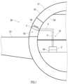
- FIG. 1 shows a schematic configuration of an aircraft 50 including a loop heat pipe 10 according to an exemplary embodiment of the present disclosure.
- the loop heat pipe 10 of FIG. 1 includes an evaporator 2, a vapor conduit 4, a condenser 3, and a liquid conduit 5, which are connected to form a closed loop.
- the closed loop is charged with a working fluid which is a condensable fluid.
- the working fluid naturally circulates in the loop heat pipe 10 by means of phase changes and gravity.
- the working fluid is not limited to a particular type, and may be a condensable fluid commonly used as a working fluid in heat pipes. Examples of the condensable fluid include water, an alcohol, ammonia, a fluorocarbon, a hydrofluorocarbon, a hydrofluoroether, and a mixture of these fluids.
- the evaporator 2 is thermally connected to a heat generator 99 which is a heat source.
- the liquid-phase working fluid absorbs heat from the heat generator 99, and part of the working fluid boils into a gas phase.
- the gas-liquid two-phase working fluid moves in the vapor conduit 4 connecting the outlet of the evaporator 2 and the inlet of the condenser 3 under the action of pressure difference and buoyancy, thereby reaching the condenser 3.
- the condenser 3 is located above the evaporator 2.
- the condenser 3 includes a cooling path (not shown), and the two-phase working fluid releases heat and is cooled into the liquid phase while passing through the cooling path.
- the liquid-phase working fluid descends in the liquid conduit 5 connecting the outlet of the condenser 3 and the inlet of the evaporator 2 under the action of gravity, thereby returning to the evaporator 2.
- the loop heat pipe 10 configured as described above is mounted on a transportation machine.
- the transportation machine include watercrafts (including submersibles), railcars, automobiles, and aircrafts.
- the loop heat pipe 10 is mounted on the aircraft 50 which is an example of the transportation machine.
- the allowable tilt angle during normal operation is ⁇ °. During normal operation, the aircraft 50 is tiltable from the horizontal to the allowable tilt angle.
- FIG. 1 partially shows a fuselage 51 and main wing 53 of the aircraft 50.
- the fuselage 51 has a multilayer structure including an outer panel 52 and an interior wall 54 closer to the cabin than the outer panel 52.
- the temperature inside the cooling chamber 55 is low because of cold energy transferred from the outer panel 52 which during flight is exposed to outside air having a considerably lower temperature than that near the ground.
- the outer panel 52 may include an air inlet and air outlet communicating with the cooling chamber 55, and outside air may be introduced into the cooling chamber 55 during flight.
- the condenser 3 In the aircraft 50, the condenser 3 is located in the cooling chamber 55, while the heat generator 99 and the evaporator 2 thermally connected to the heat generator 99 are located closer to the cabin than the interior wall 54. In the cooling chamber 55, there is a fan 56 forcing a gas stream to pass the condenser 3.
- the condenser 3 condenses the working fluid using cold energy of outside air.
- the heat generator 99 include, but are not limited to: an electronic device including heat-generating parts, such as a control board, an engine control unit (ECU), or a computer; a friction heat-generating mechanical part such as a bearing; and a battery.
- ECU engine control unit
- air inside the cabin may be a heat source.
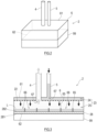
- FIG. 2 is a perspective view of the evaporator 2 according to this exemplary embodiment.
- FIG. 3 is a side view for illustrating the internal structure of the evaporator 2.
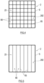
- FIG. 4 is a plan view showing the interior of the evaporator 2 to illustrate liquid retainers 66.
- FIG. 5 is a plan view showing the interior of the evaporator 2 to illustrate a variant of the liquid retainers 66.
- the evaporator 2 includes a housing 6 and a heat receiver 28 located on a bottom surface 62 of the housing 6.
- the housing 6 is in the shape of a rectangular parallelepiped in which the top and bottom surfaces 61 and 62 have the largest area.
- the housing 6 includes an accommodation chamber 23 that accommodates the working fluid.
- a part or all of the bottom surface 62 of the housing 6 is formed by the heat receiver 28.
- the heat receiver 28 is a plate made of a metal material with high thermal conductivity such as copper.
- the heat receiver 28 includes a heat-receiving surface 281 on the exterior of the housing 6 and a boiling surface 282 facing the accommodation chamber 23 inside the housing 6.
- the heat-receiving surface 281 is thermally connected to the heat generator 99 located below the evaporator 2 and receives heat from the heat generator 99.
- the accommodation chamber 23 is divided by a porous plate 22 into an upper chamber 24 above the porous plate 22 and a lower chamber 25 below the porous plate 22.
- the porous plate 22 is parallel to the top and bottom surfaces 61 and 62 of the housing 6.
- the porous plate 22 includes a large number of pores and permits the working fluid to pass through the pores.
- At least one working fluid inlet 67 opens into the upper chamber 24.
- the working fluid inlet 67 desirably opens at the highest level in the upper chamber 24.
- the working fluid inlet 67 according to this exemplary embodiment opens at the top surface 61 of the housing 6.
- the working fluid inlet 67 is connected to the liquid conduit 5 extending upward.
- At least one working fluid outlet 68 opens into the lower chamber 25.
- the working fluid outlet 68 desirably opens at the highest level in the lower chamber 25.
- the working fluid outlet 68 according to this exemplary embodiment opens at the porous plate 22 forming the ceiling of the lower chamber 25.
- the working fluid outlet 68 may be located, for example, on a side wall of the housing 6 or at a tip of a conduit inserted into the lower chamber 25 through the housing 6.
- the working fluid outlet 68 is connected to the vapor conduit 4 extending upward.
- the bottom of the lower chamber 25 is divided into liquid retainers 66 by a partition 65.
- Each liquid retainer 66 accommodates the liquid-phase working fluid.
- the partition 65 is made of, for example, a metal material with high thermal conductivity such as copper.
- the material of the partition 65 is not limited to metal materials.
- the partition 65 according to this exemplary embodiment is a plate-like structure extending vertically from the boiling surface 282 of the heat receiver 28 which is the floor of the accommodation chamber 23 (in particular, the lower chamber 25).
- the liquid retainers 66 are recesses arranged in directions in which the transportation machine is tilted ("tilt directions").
- a grid-shaped partition 65 extending vertically from the bottom surface of the lower chamber 25 defines square liquid retainers 66 at the bottom of the lower chamber 25.
- the liquid retainers 66 are not limited to this form.
- partitions 65 parallel to one another and extending vertically from the floor of the lower chamber 25 may define the rectangular liquid retainers 66 at the bottom of the lower chamber 25.
- the partition 65 is not limited to the above forms and may be in any form as long as the partition 65 defines the liquid retainers 66 at the bottom of the lower chamber 25.
- the partition 65 may be a plate extending vertically from the boiling surface 282 of the heat receiver 28.
- the partition 65 may be a result of forming the liquid retainers 66 by machining a heat-transfer block in contact with the boiling surface 282.
- the liquid-phase working fluid flows into the upper chamber 24 through the liquid conduit 5 and the working fluid inlet 67.
- the working fluid enters the lower chamber 25 from the upper chamber 24 through the pores of the porous plate 22 and falls into the liquid retainers 66 of the lower chamber 25. Due to flow resistance accompanying passage through the pores, the working fluid stays temporarily in the upper chamber 24 and spreads horizontally on the porous plate 22, rather than immediately flowing down into the lower chamber 25. Consequently, the liquid-phase working fluid staying in the upper chamber 24 forms a liquid layer with a vertical thickness in the upper chamber 24.
- the working fluid in the upper chamber 24 is delivered not only to pores directly below the working fluid inlet 67 but also to pores horizontally away from the working fluid inlet 67.
- the working fluid falls through the large number of pores distributed evenly over the entire porous plate 22.
- the working fluid is delivered not only to the liquid retainers 66 directly below the working fluid inlet 67 but also to the liquid retainers 66 horizontally away from the working fluid inlet 67.
- the liquid surface L of the liquid-phase working fluid accommodated in the liquid retainers 66 is at a lower level than the top of the partition 65 when the boiling surface 282 is in a horizontal position.
- the liquid surface L may be at the same or a higher level than the top of the partition 65.
- the heat that the heat receiver 28 receives from the heat generator 99 is released to the working fluid through the boiling surface 282 and the partition 65.
- the heat causes at least part of the liquid-phase working fluid in the liquid retainers 66 to boil into a gas phase. Consequently, the region above the liquid surface L in the lower chamber 25 is filled with the gas-phase working fluid (or the two-phase working fluid including the gas and liquid phases). Strictly speaking, there is no liquid surface L in the two-phase fluid.
- a boundary plane at which the volume percentage of the gas (void percentage) in the gas-liquid two-phase flow is a given value can be defined as an imaginary liquid surface L.
- the porous plate 22 includes a large number of pores distributed regularly and evenly over the entire porous plate 22.
- the pores are not limited to being circular, and the porous plate 22 may be, for example, a perforated metal or a metal net.
- the total area of the porous plate 22 depends on the size of the housing 6 of the evaporator 2.
- selectable parameters of the porous plate 22 are the number of pores, the pore size, and the plate thickness.
- the pore size may be an average size of the pores.
- first pressure P1 corresponds to a difference calculated by subtracting the following pressure drops from the hydraulic head pressure applied to the porous plate 22 by the working fluid present in the upper chamber 24 and liquid conduit 5: a pressure drop accompanying passage of the working fluid through the liquid conduit 5; a pressure drop accompanying an abrupt expansion of flow path upon entry of the working fluid from the liquid conduit 5 into the upper chamber 24; and a pressure drop caused by the surface tension of the working fluid.
- the first pressure P1 may be considered approximately equal to the hydraulic head pressure.
- the second pressure P2 is a pressure applied to the porous plate 22 by the working fluid present in the lower chamber 25, and varies according to the amount of evaporation of the working fluid in the lower chamber 25.
- the first pressure P1 must be greater than the sum of the second pressure P2 and the pressure drop ⁇ p of the working fluid passing through the porous plate 22 (P1 > P2 + ⁇ p).
- the open area ratio ⁇ of the porous plate 22 may be set so that the first pressure P1 during rated operation is greater than the sum of the second pressure P2 and the pressure drop ⁇ p during rated operation.
- the first pressure P1 is significantly greater than the sum of the second pressure P2 and the pressure drop ⁇ p of the working fluid passing through the porous plate 22, the working fluid entering the upper chamber 24 flows out into the lower chamber 25 without staying in the upper chamber 24.
- the pressure drop ⁇ p of the working fluid passing through the porous plate 22 can be determined by a known equation shown below in Mathematical Formula 1, and the pressure drop for ensuring the working pressure in a desired operation state can be appropriately set.
- the parameters defining the pressure drop ⁇ p of the working fluid passing through the pores of the porous plate 22 are the density ⁇ of the working fluid, the average flow velocity u 0 of the working fluid, and the coefficient of drag ⁇ .
- the parameters defining the coefficient of drag ⁇ are the open area ratio ⁇ of the porous plate 22, the coefficient of friction drag ⁇ , the equivalent diameter d h of the pores, and the function ⁇ with respect to the ratio between the thickness (l) of the porous plate 22 and the pore size.
- the open area ratio ⁇ of the porous plate 22 is chosen based on the pressure drop ⁇ p.
- the open area ratio ⁇ of the porous plate 22 is defined as the ratio of the sum of the areas of the pores to the total area of the porous plate 22.
- the thickness of the porous plate 22 is chosen in view of a plate strength suitable for the open area ratio ⁇ .
- the thickness l of the porous plate 22 is desirably small, but the porous plate 22 could lack sufficient strength if the thickness l is less than 0.01 mm.
- the pressure drop ⁇ p across the porous plate 22 is sensitive to variations in the open area ratio ⁇ and equivalent diameter d h of the porous plate 22.
- One of the parameters defining the equivalent diameter d h is the cross-sectional area of flow through the pores, and the equivalent diameter d h is a function of the pore size.
- the combination of the pore size and the number of the pores can be chosen based on the open area ratio ⁇ . Desirably, the pore size is 0.01 mm or more. Depending on the type of the working fluid, a pore size of less than 0.01 mm could cause an excessive pump head leading to interrupted flow of the working fluid.
- the use of the porous plate 22 with a suitable open area ratio ⁇ allows the working fluid to penetrate through the porous plate 22 evenly from the upper chamber 24 into the lower chamber 25.
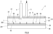
- the pressure drop ⁇ p across the porous plate 22 can be set so as to prevent passage of the working fluid through the porous plate 22 until the liquid layer 71 in the upper chamber 24 reaches a given thickness.
- the working fluid spreads evenly on the porous plate 22 since passage of the working fluid through the porous plate 22 is prevented until the working fluid in the upper chamber 24 forms a layer with a given thickness.
- the working fluid can penetrate through the porous plate 22 evenly from the upper chamber 24 into the lower chamber 25.
- the pressure drop ⁇ p across the porous plate 22 can be set so as to prevent the working fluid from flowing back from the lower chamber 25 into the upper chamber 24.
- the liquid-phase working fluid penetrates through the porous plate 22 into the lower chamber 25 when the flow rate of the working fluid flowing into the evaporator 2 or the amount of evaporation of the working fluid in the evaporator 2 is in a given rated range.
- the pressure variation (pulsation) is mitigated by the porous plate 22 and the working fluid in the upper chamber 24.
- an evaporator 2 is an evaporator that receives heat from a heat generator 99 to change at least part of a working fluid from a liquid phase to a gas phase, the evaporator 2 including: a housing 6 including an accommodation chamber 23 that accommodates the working fluid; and a heat receiver 28 located on a bottom surface 62 of the housing 6 and thermally connected to the heat generator 99.
- the housing 6 includes: a porous plate 22 dividing the accommodation chamber 23 into an upper chamber 24 and a lower chamber 25 and including a large number of pores through which the upper and lower chambers 24 and 25 communicate with each other; at least one working fluid inlet 67 opening into the upper chamber 24; a partition 65 dividing a bottom of the lower chamber 25 into liquid retainers 66; and at least one working fluid outlet 68 opening into the lower chamber 25 and located above the partition 65.
- a loop heat pipe 10 includes: the above evaporator 2 that changes part of a working fluid from a liquid phase to a gas phase; a condenser 3 that changes the working fluid from the gas phase to the liquid phase; a vapor conduit 4 connecting the working fluid outlet 68 of the evaporator 2 and an inlet of the condenser 3; and a liquid conduit 5 connecting an outlet of the condenser 3 and the working fluid inlet 67 of the evaporator 2.
- the liquid-phase working fluid flowing into the upper chamber 24 of the accommodation chamber 23 of the evaporator 2 enters the lower chamber 25 through the pores of the porous plate 22 and falls into the liquid retainers 66 of the lower chamber 25. Due to flow resistance accompanying passage through the pores, the working fluid in the upper chamber 24 spreads on the porous plate 22 rather than immediately flowing down into the lower chamber 25.
- the working fluid in the upper chamber 24 is delivered not only to pores directly below the working fluid inlet 67 but also to pores horizontally away from the working fluid inlet 67, and then falls into the lower chamber 25.
- the working fluid is delivered not only to the liquid retainers 66 directly below the working fluid inlet 67 but also to the liquid retainers 66 horizontally away from the working fluid inlet 67.
- the liquid-phase working fluid in the liquid retainers 66 is blocked by the partition 65 from flowing downward along the tilted bottom surface 62 and remains in the liquid retainers 66.
- the working fluid remains at the bottom of the accommodation chamber 23, and the heat receiver 28 and the working fluid can be kept in thermal contact.
- the heat receiver 28 has dry portions that are not in thermal contact with the working fluid, the dry portions are distributed over different zones of the heat generator 99 with which the heat receiver 28 is in thermal contact, rather than being localized over a particular zone of the heat generator 99.
- the entire region of the heat generator 99 that is in contact with the heat receiver 28 can be cooled efficiently.
- the upper chamber 24 includes a liquid layer 71 having a given thickness and including the liquid-phase working fluid staying temporarily in the upper chamber 24 after flowing into the upper chamber 24 through the working fluid inlet 67.
- the porous plate 22 has an open area ratio ⁇ that allows the working fluid to stay temporarily in the upper chamber 24 so that the upper chamber 24 includes a liquid layer 71 having a given thickness and including the liquid-phase working fluid.
- the hydraulic head pressure of the liquid-phase working fluid flowing into the upper chamber 24 of the evaporator 2 can prevent back flow of the working fluid from the lower chamber 25 into the upper chamber 24. Additionally, the working fluid can penetrate from the upper chamber 24 into the lower chamber 25 through the large number of pores distributed over the entire porous plate 22.
Landscapes
- Engineering & Computer Science (AREA)
- Microelectronics & Electronic Packaging (AREA)
- Physics & Mathematics (AREA)
- Thermal Sciences (AREA)
- Sustainable Development (AREA)
- Life Sciences & Earth Sciences (AREA)
- Mechanical Engineering (AREA)
- General Engineering & Computer Science (AREA)
- General Health & Medical Sciences (AREA)
- Pulmonology (AREA)
- Aviation & Aerospace Engineering (AREA)
- Health & Medical Sciences (AREA)
- Heat-Exchange Devices With Radiators And Conduit Assemblies (AREA)
- Cooling Or The Like Of Semiconductors Or Solid State Devices (AREA)
- Cooling Or The Like Of Electrical Apparatus (AREA)
Abstract
Description
- The present disclosure relates to an evaporator and a loop heat pipe including the evaporator.
- A loop heat pipe technology has been traditionally known which uses phase changes of a working fluid to achieve high-density heat transport. A heat transport system employing such a loop heat pipe has been used, for example, to cool an electronic device such as a computer or home electric appliance. In some loop heat pipes, the working fluid is circulated by means of capillary force and/or gravity.
- A loop heat pipe includes a closed loop formed by an evaporator, a condenser, a vapor conduit leading from the evaporator to the condenser, and a liquid conduit leading from the condenser to the evaporator. The closed loop is charged with a working fluid. In the evaporator, the working fluid in a liquid phase is heated by heat transferred from a heat generator, and a part of the working fluid changes into a gas phase. The gas-liquid two-phase working fluid moves in the vapor conduit under the action of pressure difference and buoyancy and reaches the condenser. In the condenser, the working fluid is cooled into the liquid phase. The liquid-phase working fluid returns to the evaporator under the action of capillary force and/or gravity. In this manner, the loop heat pipe allows the working fluid to circulate in the two-phase closed loop and transport heat from the evaporator to the condenser, thereby cooling the heat generator thermally connected to the evaporator.
- Patent Literature 1 proposes an evaporator used in a loop heat pipe as described above, and the evaporator includes a wick located in a lower portion of the evaporator. The pores of the wick are filled with a working fluid, and the liquid-phase working fluid remains in the evaporator while the loop heat pipe is not in operation.
- PTL 1:
Japanese Patent No. 5741354 - Electronic devices have become more and more sophisticated and miniaturized, and this has recently led to a growing demand for thermal management in transportation machines such as watercrafts, railcars, automobiles, and aircrafts which are equipped with a large number of electronic devices. Some transportation machines incorporate a loop heat pipe as described above which uses gravity for circulation of a working fluid, and such a transportation machine, the position of the body of which constantly changes, suffers a position change-induced decrease in the drive force for allowing the working fluid to circulate and a corresponding decrease in the heat transport rate.
- A type of evaporator includes a heat receiver located at the bottom of a container accommodating a working fluid, and the heat receiver is thermally connected to a heat generator. In case that such an evaporator is tilted, a situation can arise where the liquid-phase working fluid retained at the bottom of the container is not in contact with a part of the heat receiver. This leads to the heat receiver having a dry portion not in contact with the liquid-phase working fluid and a wet portion in contact with the liquid-phase working fluid. As the working fluid does not evaporate in the dry portion, the dry portion absorbs a smaller amount of heat than the wet portion. Thus, the dry portion exhibits a lower ability to cool the heat generator than the wet portion, and consequently the heat generator could be unevenly cooled.
- The present disclosure has been made in view of the above circumstances, and an object of the present disclosure is to provide an evaporator and a loop heat pipe including the evaporator, the evaporator including a heat receiver located at the bottom of the evaporator and thermally connected to a heat generator, the evaporator and loop heat pipe being capable of effectively cooling the heat generator in contact with the heat receiver even in case that the position of the evaporator is changed.
- An evaporator according to one aspect of the present disclosure is an evaporator that receives heat from a heat generator to change at least part of a working fluid from a liquid phase to a gas phase, the evaporator including: a housing including an accommodation chamber that accommodates the working fluid; and a heat receiver located on a bottom surface of the housing and thermally connected to the heat generator. The housing includes: a porous plate dividing the accommodation chamber into an upper chamber and a lower chamber and including a large number of pores through which the upper and lower chambers communicate with each other; at least one working fluid inlet opening into the upper chamber; a partition dividing a bottom of the lower chamber into liquid retainers; and at least one working fluid outlet opening into the lower chamber and located above the partition.
- A loop heat pipe according to one aspect of the present disclosure includes: the above evaporator that changes at least part of a working fluid from a liquid phase to a gas phase; a condenser that changes the working fluid from the gas phase to the liquid phase; a vapor conduit connecting the working fluid outlet of the evaporator and an inlet of the condenser; and a liquid conduit connecting an outlet of the condenser and the working fluid inlet of the evaporator.
- In the evaporator and loop heat pipe configured as described above, the liquid-phase working fluid flowing into the upper chamber of the accommodation chamber of the evaporator enters the lower chamber through the pores of the porous plate and falls into the liquid retainers of the lower chamber. Due to flow resistance accompanying passage through the pores, the working fluid in the upper chamber spreads on the porous plate rather than immediately flowing down into the lower chamber. Thus, the working fluid in the upper chamber is delivered not only to pores directly below the working fluid inlet but also to pores horizontally away from the working fluid inlet, and then falls into the lower chamber. As such, the working fluid is delivered not only to the liquid retainers directly below the working fluid inlet but also to the liquid retainers horizontally away from the working fluid inlet.
- In case that the bottom surface of the housing of the evaporator is tilted from the horizontal, the liquid-phase working fluid in the liquid retainers is blocked by the partition from flowing downward along the tilted bottom surface and remains in the liquid retainers. Thus, in case that the position of the evaporator is changed and the bottom surface of the housing is tilted from the horizontal, the working fluid remains at the bottom of the accommodation chamber, and the heat receiver and the working fluid can be kept in thermal contact. Even in case that the heat receiver has dry portions that are not in thermal contact with the working fluid, the dry portions are distributed over different zones of the heat generator with which the heat receiver is in thermal contact, rather than being localized over a particular zone of the heat generator. Thus, despite the change in the position of the evaporator, the entire region of the heat generator that is in contact with the heat receiver can be cooled efficiently.
- The present disclosure can provide an evaporator and a loop heat pipe including the evaporator, the evaporator including a heat receiver located at the bottom of the evaporator and thermally connected to a heat generator, the evaporator and loop heat pipe being capable of effectively cooling the heat generator in contact with the heat receiver even in case that the position of the evaporator is changed.
-
-
FIG. 1 shows a schematic configuration of an aircraft including a loop heat pipe according to an exemplary embodiment of the present disclosure. -
FIG. 2 is a perspective view of an evaporator. -
FIG. 3 is a side view for illustrating the internal structure of the evaporator. -
FIG. 4 is a plan view showing the interior of the evaporator to illustrate liquid retainers. -
FIG. 5 is a plan view showing the interior of the evaporator to illustrate a variant of the liquid retainers. -
FIG. 6 is a side view of the evaporator in a state where the amount of the liquid-phase working fluid flowing into the evaporator is small. - Hereinafter, exemplary embodiments of the present disclosure will be described with reference to the drawings.
FIG. 1 shows a schematic configuration of anaircraft 50 including aloop heat pipe 10 according to an exemplary embodiment of the present disclosure. - The
loop heat pipe 10 ofFIG. 1 includes anevaporator 2, avapor conduit 4, acondenser 3, and aliquid conduit 5, which are connected to form a closed loop. The closed loop is charged with a working fluid which is a condensable fluid. The working fluid naturally circulates in theloop heat pipe 10 by means of phase changes and gravity. The working fluid is not limited to a particular type, and may be a condensable fluid commonly used as a working fluid in heat pipes. Examples of the condensable fluid include water, an alcohol, ammonia, a fluorocarbon, a hydrofluorocarbon, a hydrofluoroether, and a mixture of these fluids. - The
evaporator 2 is thermally connected to aheat generator 99 which is a heat source. In theevaporator 2, the liquid-phase working fluid absorbs heat from theheat generator 99, and part of the working fluid boils into a gas phase. The gas-liquid two-phase working fluid moves in thevapor conduit 4 connecting the outlet of theevaporator 2 and the inlet of thecondenser 3 under the action of pressure difference and buoyancy, thereby reaching thecondenser 3. - The
condenser 3 is located above theevaporator 2. Thecondenser 3 includes a cooling path (not shown), and the two-phase working fluid releases heat and is cooled into the liquid phase while passing through the cooling path. The liquid-phase working fluid descends in theliquid conduit 5 connecting the outlet of thecondenser 3 and the inlet of theevaporator 2 under the action of gravity, thereby returning to theevaporator 2. - The
loop heat pipe 10 configured as described above is mounted on a transportation machine. Examples of the transportation machine include watercrafts (including submersibles), railcars, automobiles, and aircrafts. In this exemplary embodiment, theloop heat pipe 10 is mounted on theaircraft 50 which is an example of the transportation machine. For theaircraft 50, the allowable tilt angle during normal operation is α°. During normal operation, theaircraft 50 is tiltable from the horizontal to the allowable tilt angle. -
FIG. 1 partially shows afuselage 51 andmain wing 53 of theaircraft 50. Thefuselage 51 has a multilayer structure including anouter panel 52 and aninterior wall 54 closer to the cabin than theouter panel 52. There is a coolingchamber 55 between theouter panel 52 and theinterior wall 54. The temperature inside the coolingchamber 55 is low because of cold energy transferred from theouter panel 52 which during flight is exposed to outside air having a considerably lower temperature than that near the ground. Alternatively, theouter panel 52 may include an air inlet and air outlet communicating with the coolingchamber 55, and outside air may be introduced into the coolingchamber 55 during flight. - In the
aircraft 50, thecondenser 3 is located in the coolingchamber 55, while theheat generator 99 and theevaporator 2 thermally connected to theheat generator 99 are located closer to the cabin than theinterior wall 54. In the coolingchamber 55, there is afan 56 forcing a gas stream to pass thecondenser 3. Thecondenser 3 condenses the working fluid using cold energy of outside air. Examples of theheat generator 99 include, but are not limited to: an electronic device including heat-generating parts, such as a control board, an engine control unit (ECU), or a computer; a friction heat-generating mechanical part such as a bearing; and a battery. Instead of theheat generator 99, air inside the cabin may be a heat source. - The following will describe the configuration of the
evaporator 2 of theloop heat pipe 10 configured as described above.FIG. 2 is a perspective view of theevaporator 2 according to this exemplary embodiment.FIG. 3 is a side view for illustrating the internal structure of theevaporator 2.FIG. 4 is a plan view showing the interior of theevaporator 2 to illustrateliquid retainers 66.FIG. 5 is a plan view showing the interior of theevaporator 2 to illustrate a variant of theliquid retainers 66. - As shown in
FIGS. 2 and 3 , theevaporator 2 according to this exemplary embodiment includes ahousing 6 and aheat receiver 28 located on abottom surface 62 of thehousing 6. - The
housing 6 is in the shape of a rectangular parallelepiped in which the top andbottom surfaces housing 6 includes anaccommodation chamber 23 that accommodates the working fluid. A part or all of thebottom surface 62 of thehousing 6 is formed by theheat receiver 28. Theheat receiver 28 is a plate made of a metal material with high thermal conductivity such as copper. Theheat receiver 28 includes a heat-receivingsurface 281 on the exterior of thehousing 6 and a boilingsurface 282 facing theaccommodation chamber 23 inside thehousing 6. The heat-receivingsurface 281 is thermally connected to theheat generator 99 located below theevaporator 2 and receives heat from theheat generator 99. - The
accommodation chamber 23 is divided by aporous plate 22 into anupper chamber 24 above theporous plate 22 and alower chamber 25 below theporous plate 22. Theporous plate 22 is parallel to the top andbottom surfaces housing 6. Theporous plate 22 includes a large number of pores and permits the working fluid to pass through the pores. - At least one working
fluid inlet 67 opens into theupper chamber 24. The workingfluid inlet 67 desirably opens at the highest level in theupper chamber 24. The workingfluid inlet 67 according to this exemplary embodiment opens at thetop surface 61 of thehousing 6. The workingfluid inlet 67 is connected to theliquid conduit 5 extending upward. - At least one working fluid outlet 68 opens into the
lower chamber 25. The working fluid outlet 68 desirably opens at the highest level in thelower chamber 25. The working fluid outlet 68 according to this exemplary embodiment opens at theporous plate 22 forming the ceiling of thelower chamber 25. Alternatively, the working fluid outlet 68 may be located, for example, on a side wall of thehousing 6 or at a tip of a conduit inserted into thelower chamber 25 through thehousing 6. The working fluid outlet 68 is connected to thevapor conduit 4 extending upward. - The bottom of the
lower chamber 25 is divided intoliquid retainers 66 by apartition 65. Eachliquid retainer 66 accommodates the liquid-phase working fluid. Thepartition 65 is made of, for example, a metal material with high thermal conductivity such as copper. The material of thepartition 65 is not limited to metal materials. Thepartition 65 according to this exemplary embodiment is a plate-like structure extending vertically from the boilingsurface 282 of theheat receiver 28 which is the floor of the accommodation chamber 23 (in particular, the lower chamber 25). - The
liquid retainers 66 are recesses arranged in directions in which the transportation machine is tilted ("tilt directions"). In this exemplary embodiment, as shown inFIG. 4 , a grid-shapedpartition 65 extending vertically from the bottom surface of thelower chamber 25 defines squareliquid retainers 66 at the bottom of thelower chamber 25. Theliquid retainers 66 are not limited to this form. For example, as shown inFIG. 5 ,partitions 65 parallel to one another and extending vertically from the floor of thelower chamber 25 may define the rectangularliquid retainers 66 at the bottom of thelower chamber 25. - The
partition 65 is not limited to the above forms and may be in any form as long as thepartition 65 defines theliquid retainers 66 at the bottom of thelower chamber 25. For example, thepartition 65 may be a plate extending vertically from the boilingsurface 282 of theheat receiver 28. For example, thepartition 65 may be a result of forming theliquid retainers 66 by machining a heat-transfer block in contact with the boilingsurface 282. - In the
evaporator 2 configured as described above, the liquid-phase working fluid flows into theupper chamber 24 through theliquid conduit 5 and the workingfluid inlet 67. The working fluid enters thelower chamber 25 from theupper chamber 24 through the pores of theporous plate 22 and falls into theliquid retainers 66 of thelower chamber 25. Due to flow resistance accompanying passage through the pores, the working fluid stays temporarily in theupper chamber 24 and spreads horizontally on theporous plate 22, rather than immediately flowing down into thelower chamber 25. Consequently, the liquid-phase working fluid staying in theupper chamber 24 forms a liquid layer with a vertical thickness in theupper chamber 24. Thus, the working fluid in theupper chamber 24 is delivered not only to pores directly below the workingfluid inlet 67 but also to pores horizontally away from the workingfluid inlet 67. - In the manner as described above, the working fluid falls through the large number of pores distributed evenly over the entire
porous plate 22. Thus, the working fluid is delivered not only to theliquid retainers 66 directly below the workingfluid inlet 67 but also to theliquid retainers 66 horizontally away from the workingfluid inlet 67. The liquid surface L of the liquid-phase working fluid accommodated in theliquid retainers 66 is at a lower level than the top of thepartition 65 when the boilingsurface 282 is in a horizontal position. The liquid surface L may be at the same or a higher level than the top of thepartition 65. - The heat that the
heat receiver 28 receives from theheat generator 99 is released to the working fluid through the boilingsurface 282 and thepartition 65. The heat causes at least part of the liquid-phase working fluid in theliquid retainers 66 to boil into a gas phase. Consequently, the region above the liquid surface L in thelower chamber 25 is filled with the gas-phase working fluid (or the two-phase working fluid including the gas and liquid phases). Strictly speaking, there is no liquid surface L in the two-phase fluid. However, given that in the working fluid located in thelower chamber 25, the volume proportion of the gas present in the liquid increases upward, a boundary plane at which the volume percentage of the gas (void percentage) in the gas-liquid two-phase flow is a given value (e.g., 50%) can be defined as an imaginary liquid surface L. - The
porous plate 22 includes a large number of pores distributed regularly and evenly over the entireporous plate 22. The pores are not limited to being circular, and theporous plate 22 may be, for example, a perforated metal or a metal net. The total area of theporous plate 22 depends on the size of thehousing 6 of theevaporator 2. Thus, selectable parameters of theporous plate 22 are the number of pores, the pore size, and the plate thickness. The pore size may be an average size of the pores. - For the
porous plate 22, the pressure applied at the pores from the direction of theupper chamber 24 is referred to as "first pressure P1", and the pressure applied at the pores from the direction of thelower chamber 25 is referred to as "second pressure P2". The first pressure P1 corresponds to a difference calculated by subtracting the following pressure drops from the hydraulic head pressure applied to theporous plate 22 by the working fluid present in theupper chamber 24 and liquid conduit 5: a pressure drop accompanying passage of the working fluid through theliquid conduit 5; a pressure drop accompanying an abrupt expansion of flow path upon entry of the working fluid from theliquid conduit 5 into theupper chamber 24; and a pressure drop caused by the surface tension of the working fluid. The first pressure P1 may be considered approximately equal to the hydraulic head pressure. The second pressure P2 is a pressure applied to theporous plate 22 by the working fluid present in thelower chamber 25, and varies according to the amount of evaporation of the working fluid in thelower chamber 25. - For the working fluid to pass from the
upper chamber 24 to thelower chamber 25, the first pressure P1 must be greater than the sum of the second pressure P2 and the pressure drop Δp of the working fluid passing through the porous plate 22 (P1 > P2 + Δp). Thus, the open area ratio ε of theporous plate 22 may be set so that the first pressure P1 during rated operation is greater than the sum of the second pressure P2 and the pressure drop Δp during rated operation. However, if the first pressure P1 is significantly greater than the sum of the second pressure P2 and the pressure drop Δp of the working fluid passing through theporous plate 22, the working fluid entering theupper chamber 24 flows out into thelower chamber 25 without staying in theupper chamber 24. The pressure drop Δp of the working fluid passing through theporous plate 22 can be determined by a known equation shown below in Mathematical Formula 1, and the pressure drop for ensuring the working pressure in a desired operation state can be appropriately set.
Mathematical Formula 1


-
- dh: Equivalent diameter [m] = 4 × wetted perimeter [m]/cross-sectional area of flow [m2]
- Re: Reynolds number [-]
- l: Thickness of porous plate [m]
- ΔP: Pressure drop across porous plate [Pa]
- u0: Average flow velocity of fluid passing through pores [m/s]
- ε: Open area ratio of porous plate [-] = pore area [m2]/porous plate area [m2]
- ζ: Coefficient of drag [-]
- λ: Coefficient of friction drag [-]
- µ: Viscosity of fluid [Pa·s]
- ρ: Density of fluid [kg/m3]
- τ: Function with respect to ratio between thickness of porous plate and pore size [-]
- The parameters defining the pressure drop Δp of the working fluid passing through the pores of the
porous plate 22 are the density ρ of the working fluid, the average flow velocity u0 of the working fluid, and the coefficient of drag ζ. The parameters defining the coefficient of drag ζ are the open area ratio ε of theporous plate 22, the coefficient of friction drag λ, the equivalent diameter dh of the pores, and the function τ with respect to the ratio between the thickness (l) of theporous plate 22 and the pore size. The open area ratio ε of theporous plate 22 is chosen based on the pressure drop Δp. The open area ratio ε of theporous plate 22 is defined as the ratio of the sum of the areas of the pores to the total area of theporous plate 22. The thickness of theporous plate 22 is chosen in view of a plate strength suitable for the open area ratio ε. The thickness l of theporous plate 22 is desirably small, but theporous plate 22 could lack sufficient strength if the thickness l is less than 0.01 mm. - The pressure drop Δp across the
porous plate 22 is sensitive to variations in the open area ratio ε and equivalent diameter dh of theporous plate 22. One of the parameters defining the equivalent diameter dh is the cross-sectional area of flow through the pores, and the equivalent diameter dh is a function of the pore size. The combination of the pore size and the number of the pores can be chosen based on the open area ratio ε. Desirably, the pore size is 0.01 mm or more. Depending on the type of the working fluid, a pore size of less than 0.01 mm could cause an excessive pump head leading to interrupted flow of the working fluid. - In the
evaporator 2, the use of theporous plate 22 with a suitable open area ratio ε allows the working fluid to penetrate through theporous plate 22 evenly from theupper chamber 24 into thelower chamber 25. - For example, the pressure drop Δp across the
porous plate 22 can be set so as to prevent passage of the working fluid through theporous plate 22 until the liquid layer 71 in theupper chamber 24 reaches a given thickness. In this case, as shown inFIG. 6 , the working fluid spreads evenly on theporous plate 22 since passage of the working fluid through theporous plate 22 is prevented until the working fluid in theupper chamber 24 forms a layer with a given thickness. As a result, the working fluid can penetrate through theporous plate 22 evenly from theupper chamber 24 into thelower chamber 25. - For example, the pressure drop Δp across the
porous plate 22 can be set so as to prevent the working fluid from flowing back from thelower chamber 25 into theupper chamber 24. In this case, the liquid-phase working fluid penetrates through theporous plate 22 into thelower chamber 25 when the flow rate of the working fluid flowing into theevaporator 2 or the amount of evaporation of the working fluid in theevaporator 2 is in a given rated range. In case that the pressure of the working fluid in thelower chamber 25 sharply increases due to an abrupt increase in the amount of evaporation of the working fluid, the pressure variation (pulsation) is mitigated by theporous plate 22 and the working fluid in theupper chamber 24. - As described above, an
evaporator 2 according to this exemplary embodiment is an evaporator that receives heat from aheat generator 99 to change at least part of a working fluid from a liquid phase to a gas phase, theevaporator 2 including: ahousing 6 including anaccommodation chamber 23 that accommodates the working fluid; and aheat receiver 28 located on abottom surface 62 of thehousing 6 and thermally connected to theheat generator 99. Thehousing 6 includes: aporous plate 22 dividing theaccommodation chamber 23 into anupper chamber 24 and alower chamber 25 and including a large number of pores through which the upper andlower chambers fluid inlet 67 opening into theupper chamber 24; apartition 65 dividing a bottom of thelower chamber 25 intoliquid retainers 66; and at least one working fluid outlet 68 opening into thelower chamber 25 and located above thepartition 65. - A
loop heat pipe 10 according to this exemplary embodiment includes: theabove evaporator 2 that changes part of a working fluid from a liquid phase to a gas phase; acondenser 3 that changes the working fluid from the gas phase to the liquid phase; avapor conduit 4 connecting the working fluid outlet 68 of theevaporator 2 and an inlet of thecondenser 3; and aliquid conduit 5 connecting an outlet of thecondenser 3 and the workingfluid inlet 67 of theevaporator 2. - In the
evaporator 2 andloop heat pipe 10 configured as described above, the liquid-phase working fluid flowing into theupper chamber 24 of theaccommodation chamber 23 of theevaporator 2 enters thelower chamber 25 through the pores of theporous plate 22 and falls into theliquid retainers 66 of thelower chamber 25. Due to flow resistance accompanying passage through the pores, the working fluid in theupper chamber 24 spreads on theporous plate 22 rather than immediately flowing down into thelower chamber 25. Thus, the working fluid in theupper chamber 24 is delivered not only to pores directly below the workingfluid inlet 67 but also to pores horizontally away from the workingfluid inlet 67, and then falls into thelower chamber 25. As such, the working fluid is delivered not only to theliquid retainers 66 directly below the workingfluid inlet 67 but also to theliquid retainers 66 horizontally away from the workingfluid inlet 67. - In the
evaporator 2 andloop heat pipe 10 configured as described above, in case that thebottom surface 62 of thehousing 6 of theevaporator 2 is tilted from the horizontal, the liquid-phase working fluid in theliquid retainers 66 is blocked by thepartition 65 from flowing downward along the tiltedbottom surface 62 and remains in theliquid retainers 66. Thus, in case that the position of theevaporator 2 is changed and thebottom surface 62 of thehousing 6 is tilted from the horizontal, the working fluid remains at the bottom of theaccommodation chamber 23, and theheat receiver 28 and the working fluid can be kept in thermal contact. Even in case that theheat receiver 28 has dry portions that are not in thermal contact with the working fluid, the dry portions are distributed over different zones of theheat generator 99 with which theheat receiver 28 is in thermal contact, rather than being localized over a particular zone of theheat generator 99. Thus, despite the change in the position of theevaporator 2, the entire region of theheat generator 99 that is in contact with theheat receiver 28 can be cooled efficiently. - In the
evaporator 2 andloop heat pipe 10 according to this exemplary embodiment, theupper chamber 24 includes a liquid layer 71 having a given thickness and including the liquid-phase working fluid staying temporarily in theupper chamber 24 after flowing into theupper chamber 24 through the workingfluid inlet 67. To this end, in theevaporator 2 andloop heat pipe 10 according to this exemplary embodiment, theporous plate 22 has an open area ratio ε that allows the working fluid to stay temporarily in theupper chamber 24 so that theupper chamber 24 includes a liquid layer 71 having a given thickness and including the liquid-phase working fluid. - Thus, the hydraulic head pressure of the liquid-phase working fluid flowing into the
upper chamber 24 of theevaporator 2 can prevent back flow of the working fluid from thelower chamber 25 into theupper chamber 24. Additionally, the working fluid can penetrate from theupper chamber 24 into thelower chamber 25 through the large number of pores distributed over the entireporous plate 22. - Although the foregoing has described a preferred embodiment of the present disclosure, the scope of the present disclosure embraces modifications made to the details of the structures and/or functions of the above embodiment without departing from the concept of the present disclosure.
-
- 2: evaporator
- 3: condenser
- 4: vapor conduit
- 5: liquid conduit
- 6: housing
- 10: loop heat pipe
- 22: porous plate
- 23: accommodation chamber
- 24: upper chamber
- 25: lower chamber
- 28: heat receiver
- 62: bottom surface
- 65: partition
- 66: liquid retainer
- 67: working fluid inlet
- 68: working fluid outlet
- 71: liquid layer
- 99: heat generator
Claims (4)
- An evaporator that receives heat from a heat generator to change at least part of a working fluid from a liquid phase to a gas phase, the evaporator comprising:a housing including an accommodation chamber that accommodates the working fluid; anda heat receiver located on a bottom surface of the housing and thermally connected to the heat generator, whereinthe housing includesa porous plate dividing the accommodation chamber into an upper chamber and a lower chamber and including a large number of pores through which the upper and lower chambers communicate with each other,at least one working fluid inlet opening into the upper chamber,a partition dividing a bottom of the lower chamber into liquid retainers, andat least one working fluid outlet opening into the lower chamber and located above the partition.
- The evaporator according to claim 1, wherein the upper chamber includes a liquid layer having a given thickness and including the liquid-phase working fluid staying temporarily in the upper chamber after flowing into the upper chamber through the working fluid inlet.
- The evaporator according to claim 1, wherein the porous plate has an open area ratio that allows the working fluid to stay temporarily in the upper chamber so that the upper chamber includes a liquid layer having a given thickness and including the liquid-phase working fluid.
- A loop heat pipe comprising:the evaporator according to any one of claims 1 to 3 that changes at least part of a working fluid from a liquid phase to a gas phase;a condenser that changes the working fluid from the gas phase to the liquid phase;a vapor conduit connecting the working fluid outlet of the evaporator and an inlet of the condenser; anda liquid conduit connecting an outlet of the condenser and the working fluid inlet of the evaporator.
Applications Claiming Priority (2)
| Application Number | Priority Date | Filing Date | Title |
|---|---|---|---|
| JP2020108949A JP7535392B2 (en) | 2020-06-24 | 2020-06-24 | Evaporator and loop type heat pipe |
| PCT/JP2021/023933 WO2021261552A1 (en) | 2020-06-24 | 2021-06-24 | Evaporator and loop heat pipe |
Publications (3)
| Publication Number | Publication Date |
|---|---|
| EP4174937A1 true EP4174937A1 (en) | 2023-05-03 |
| EP4174937A4 EP4174937A4 (en) | 2024-07-24 |
| EP4174937B1 EP4174937B1 (en) | 2025-08-20 |
Family
ID=79281276
Family Applications (1)
| Application Number | Title | Priority Date | Filing Date |
|---|---|---|---|
| EP21830065.5A Active EP4174937B1 (en) | 2020-06-24 | 2021-06-24 | Evaporator and loop heat pipe |
Country Status (4)
| Country | Link |
|---|---|
| US (1) | US12484192B2 (en) |
| EP (1) | EP4174937B1 (en) |
| JP (1) | JP7535392B2 (en) |
| WO (1) | WO2021261552A1 (en) |
Families Citing this family (2)
| Publication number | Priority date | Publication date | Assignee | Title |
|---|---|---|---|---|
| TR202017018A1 (en) * | 2020-10-26 | 2022-05-23 | Aselsan Elektronik Sanayi Ve Ticaret As | Heat Pipe Design and Analysis Method with High Solution Speed |
| JP7635586B2 (en) | 2021-03-18 | 2025-02-26 | 富士電機株式会社 | Boiling Cooling Device |
Family Cites Families (13)
| Publication number | Priority date | Publication date | Assignee | Title |
|---|---|---|---|---|
| JP2819807B2 (en) * | 1990-09-03 | 1998-11-05 | 富士通株式会社 | Cooling module |
| JPH05315489A (en) | 1992-05-08 | 1993-11-26 | Fuji Electric Co Ltd | Liquid cooling system for electronic devices |
| JP3355726B2 (en) * | 1993-10-19 | 2002-12-09 | 株式会社デンソー | Boiling cooling device |
| JP2006114603A (en) * | 2004-10-13 | 2006-04-27 | Toshiba Corp | Semiconductor cooling device for vehicle |
| US7450386B2 (en) * | 2005-07-30 | 2008-11-11 | Articchoke Enterprises Llc | Phase-separated evaporator, blade-thru condenser and heat dissipation system thereof |
| US20070227703A1 (en) | 2006-03-31 | 2007-10-04 | Bhatti Mohinder S | Evaporatively cooled thermosiphon |
| TW201204994A (en) | 2010-07-30 | 2012-02-01 | Microbase Technology Corp | Lighting device, cooling/heat dissipating system and its cooling module |
| WO2013001735A1 (en) * | 2011-06-29 | 2013-01-03 | パナソニック株式会社 | Cooling system and electronic appliance equipped therewith, and electric automobile |
| JP5741354B2 (en) | 2011-09-29 | 2015-07-01 | 富士通株式会社 | Loop heat pipe and electronic equipment |
| JP6191137B2 (en) * | 2012-05-14 | 2017-09-06 | 富士通株式会社 | Cooling system |
| DE102012111489A1 (en) | 2012-11-27 | 2014-05-28 | Dr. Ing. H.C. F. Porsche Aktiengesellschaft | Device for cooling power electronic for use in motor vehicle e.g. hybrid vehicle, has separating elements that are fluidly connected to each other, and electronic components that are arranged in respective cooling chambers |
| JP6547732B2 (en) * | 2016-12-13 | 2019-07-24 | トヨタ自動車株式会社 | Evaporator |
| JP2020106209A (en) * | 2018-12-27 | 2020-07-09 | 川崎重工業株式会社 | Evaporator and loop heat pipe |
-
2020
- 2020-06-24 JP JP2020108949A patent/JP7535392B2/en active Active
-
2021
- 2021-06-24 US US18/013,026 patent/US12484192B2/en active Active
- 2021-06-24 EP EP21830065.5A patent/EP4174937B1/en active Active
- 2021-06-24 WO PCT/JP2021/023933 patent/WO2021261552A1/en not_active Ceased
Also Published As
| Publication number | Publication date |
|---|---|
| WO2021261552A1 (en) | 2021-12-30 |
| EP4174937A4 (en) | 2024-07-24 |
| US20230247793A1 (en) | 2023-08-03 |
| JP2022006611A (en) | 2022-01-13 |
| EP4174937B1 (en) | 2025-08-20 |
| JP7535392B2 (en) | 2024-08-16 |
| US12484192B2 (en) | 2025-11-25 |
Similar Documents
| Publication | Publication Date | Title |
|---|---|---|
| US6840304B1 (en) | Evaporator, a heat absorber, a thermal transport system and a thermal transport method | |
| US7013956B2 (en) | Heat pipe evaporator with porous valve | |
| KR20230026360A (en) | Scalable thermal ride-through for immersion cooled server systems | |
| CN110753822B (en) | Thermal siphon | |
| EP3905321A1 (en) | Evaporator and loop heat pipe | |
| US12484192B2 (en) | Evaporator and loop heat pipe | |
| EP3905320B1 (en) | Evaporator and loop heat pipe | |
| EP2003944A2 (en) | Method of ebullient cooling, ebullient cooling apparatus, flow channel structure and application product thereof | |
| CN104094074B (en) | The heat transfer unit (HTU) of REFRIGERATION SYSTEM DRIVEN BY CAPILLARY FORCE | |
| JP2013245875A (en) | Cooling device and electronic device | |
| US20250287550A1 (en) | Condenser on server rack door | |
| WO2014132085A1 (en) | A module for cooling one or more heat generating components | |
| EP3904811B1 (en) | Heat conveyance system and conveyance machinery | |
| JP2004020116A (en) | Flat heat pipe | |
| EP3904812A1 (en) | Loop-type heat pipe and transport device | |
| EP3904813A1 (en) | Loop-type heat pipe and transporter | |
| CN107192173B (en) | Absorption heat pump | |
| EP3904814A1 (en) | Evaporator and loop-type heat pipe | |
| RU2755365C1 (en) | Vaporizer | |
| KR102574636B1 (en) | Cooling device | |
| Pastukhov et al. | Development and investigation of a cooler for electronics on the basis of two-phase loop thermosyphons | |
| Hoang et al. | Development of a Gravity-Assist Water Loop Heat Pipe With Flat Evaporator for Waste Heat Removal | |
| JP2022070569A (en) | Boiling cooler device | |
| Vasiliev et al. | LOOP THERMOSYPHONS WITH POROUS COATING | |
| HK1078640B (en) | A pump-free water-cooling system |
Legal Events
| Date | Code | Title | Description |
|---|---|---|---|
| STAA | Information on the status of an ep patent application or granted ep patent |
Free format text: STATUS: THE INTERNATIONAL PUBLICATION HAS BEEN MADE |
|
| PUAI | Public reference made under article 153(3) epc to a published international application that has entered the european phase |
Free format text: ORIGINAL CODE: 0009012 |
|
| STAA | Information on the status of an ep patent application or granted ep patent |
Free format text: STATUS: REQUEST FOR EXAMINATION WAS MADE |
|
| 17P | Request for examination filed |
Effective date: 20230113 |
|
| AK | Designated contracting states |
Kind code of ref document: A1 Designated state(s): AL AT BE BG CH CY CZ DE DK EE ES FI FR GB GR HR HU IE IS IT LI LT LU LV MC MK MT NL NO PL PT RO RS SE SI SK SM TR |
|
| DAV | Request for validation of the european patent (deleted) | ||
| DAX | Request for extension of the european patent (deleted) | ||
| A4 | Supplementary search report drawn up and despatched |
Effective date: 20240624 |
|
| RIC1 | Information provided on ipc code assigned before grant |
Ipc: H05K 7/20 20060101ALI20240618BHEP Ipc: F28D 15/02 20060101ALI20240618BHEP Ipc: H01L 23/427 20060101AFI20240618BHEP |
|
| GRAP | Despatch of communication of intention to grant a patent |
Free format text: ORIGINAL CODE: EPIDOSNIGR1 |
|
| STAA | Information on the status of an ep patent application or granted ep patent |
Free format text: STATUS: GRANT OF PATENT IS INTENDED |
|
| INTG | Intention to grant announced |
Effective date: 20250527 |
|
| GRAS | Grant fee paid |
Free format text: ORIGINAL CODE: EPIDOSNIGR3 |
|
| GRAA | (expected) grant |
Free format text: ORIGINAL CODE: 0009210 |
|
| STAA | Information on the status of an ep patent application or granted ep patent |
Free format text: STATUS: THE PATENT HAS BEEN GRANTED |
|
| AK | Designated contracting states |
Kind code of ref document: B1 Designated state(s): AL AT BE BG CH CY CZ DE DK EE ES FI FR GB GR HR HU IE IS IT LI LT LU LV MC MK MT NL NO PL PT RO RS SE SI SK SM TR |
|
| REG | Reference to a national code |
Ref country code: GB Ref legal event code: FG4D |
|
| REG | Reference to a national code |
Ref country code: CH Ref legal event code: EP |
|
| REG | Reference to a national code |
Ref country code: IE Ref legal event code: FG4D |
|
| REG | Reference to a national code |
Ref country code: DE Ref legal event code: R096 Ref document number: 602021036820 Country of ref document: DE |
|
| REG | Reference to a national code |
Ref country code: DE Ref legal event code: R079 Ref document number: 602021036820 Country of ref document: DE Free format text: PREVIOUS MAIN CLASS: H01L0023427000 Ipc: H10W0040730000 |
|
| REG | Reference to a national code |
Ref country code: NL Ref legal event code: MP Effective date: 20250820 |
|
| PG25 | Lapsed in a contracting state [announced via postgrant information from national office to epo] |
Ref country code: IS Free format text: LAPSE BECAUSE OF FAILURE TO SUBMIT A TRANSLATION OF THE DESCRIPTION OR TO PAY THE FEE WITHIN THE PRESCRIBED TIME-LIMIT Effective date: 20251220 |
|
| PG25 | Lapsed in a contracting state [announced via postgrant information from national office to epo] |
Ref country code: NO Free format text: LAPSE BECAUSE OF FAILURE TO SUBMIT A TRANSLATION OF THE DESCRIPTION OR TO PAY THE FEE WITHIN THE PRESCRIBED TIME-LIMIT Effective date: 20251120 |
|
| REG | Reference to a national code |
Ref country code: LT Ref legal event code: MG9D |
|
| PG25 | Lapsed in a contracting state [announced via postgrant information from national office to epo] |
Ref country code: PT Free format text: LAPSE BECAUSE OF FAILURE TO SUBMIT A TRANSLATION OF THE DESCRIPTION OR TO PAY THE FEE WITHIN THE PRESCRIBED TIME-LIMIT Effective date: 20251222 |
|
| PG25 | Lapsed in a contracting state [announced via postgrant information from national office to epo] |
Ref country code: FI Free format text: LAPSE BECAUSE OF FAILURE TO SUBMIT A TRANSLATION OF THE DESCRIPTION OR TO PAY THE FEE WITHIN THE PRESCRIBED TIME-LIMIT Effective date: 20250820 |
|
| PG25 | Lapsed in a contracting state [announced via postgrant information from national office to epo] |
Ref country code: NL Free format text: LAPSE BECAUSE OF FAILURE TO SUBMIT A TRANSLATION OF THE DESCRIPTION OR TO PAY THE FEE WITHIN THE PRESCRIBED TIME-LIMIT Effective date: 20250820 Ref country code: HR Free format text: LAPSE BECAUSE OF FAILURE TO SUBMIT A TRANSLATION OF THE DESCRIPTION OR TO PAY THE FEE WITHIN THE PRESCRIBED TIME-LIMIT Effective date: 20250820 |
|
| PG25 | Lapsed in a contracting state [announced via postgrant information from national office to epo] |
Ref country code: GR Free format text: LAPSE BECAUSE OF FAILURE TO SUBMIT A TRANSLATION OF THE DESCRIPTION OR TO PAY THE FEE WITHIN THE PRESCRIBED TIME-LIMIT Effective date: 20251121 |
|
| PG25 | Lapsed in a contracting state [announced via postgrant information from national office to epo] |
Ref country code: SE Free format text: LAPSE BECAUSE OF FAILURE TO SUBMIT A TRANSLATION OF THE DESCRIPTION OR TO PAY THE FEE WITHIN THE PRESCRIBED TIME-LIMIT Effective date: 20250820 |
|
| PG25 | Lapsed in a contracting state [announced via postgrant information from national office to epo] |
Ref country code: LV Free format text: LAPSE BECAUSE OF FAILURE TO SUBMIT A TRANSLATION OF THE DESCRIPTION OR TO PAY THE FEE WITHIN THE PRESCRIBED TIME-LIMIT Effective date: 20250820 |
|
| PG25 | Lapsed in a contracting state [announced via postgrant information from national office to epo] |
Ref country code: BG Free format text: LAPSE BECAUSE OF FAILURE TO SUBMIT A TRANSLATION OF THE DESCRIPTION OR TO PAY THE FEE WITHIN THE PRESCRIBED TIME-LIMIT Effective date: 20250820 Ref country code: PL Free format text: LAPSE BECAUSE OF FAILURE TO SUBMIT A TRANSLATION OF THE DESCRIPTION OR TO PAY THE FEE WITHIN THE PRESCRIBED TIME-LIMIT Effective date: 20250820 |
|
| PG25 | Lapsed in a contracting state [announced via postgrant information from national office to epo] |
Ref country code: RS Free format text: LAPSE BECAUSE OF FAILURE TO SUBMIT A TRANSLATION OF THE DESCRIPTION OR TO PAY THE FEE WITHIN THE PRESCRIBED TIME-LIMIT Effective date: 20251120 |
|
| PG25 | Lapsed in a contracting state [announced via postgrant information from national office to epo] |
Ref country code: ES Free format text: LAPSE BECAUSE OF FAILURE TO SUBMIT A TRANSLATION OF THE DESCRIPTION OR TO PAY THE FEE WITHIN THE PRESCRIBED TIME-LIMIT Effective date: 20250820 |
|
| REG | Reference to a national code |
Ref country code: AT Ref legal event code: MK05 Ref document number: 1828327 Country of ref document: AT Kind code of ref document: T Effective date: 20250820 |
|
| PG25 | Lapsed in a contracting state [announced via postgrant information from national office to epo] |
Ref country code: SM Free format text: LAPSE BECAUSE OF FAILURE TO SUBMIT A TRANSLATION OF THE DESCRIPTION OR TO PAY THE FEE WITHIN THE PRESCRIBED TIME-LIMIT Effective date: 20250820 |
|
| PG25 | Lapsed in a contracting state [announced via postgrant information from national office to epo] |
Ref country code: DK Free format text: LAPSE BECAUSE OF FAILURE TO SUBMIT A TRANSLATION OF THE DESCRIPTION OR TO PAY THE FEE WITHIN THE PRESCRIBED TIME-LIMIT Effective date: 20250820 |
|
| PG25 | Lapsed in a contracting state [announced via postgrant information from national office to epo] |
Ref country code: AT Free format text: LAPSE BECAUSE OF FAILURE TO SUBMIT A TRANSLATION OF THE DESCRIPTION OR TO PAY THE FEE WITHIN THE PRESCRIBED TIME-LIMIT Effective date: 20250820 |
|
| PG25 | Lapsed in a contracting state [announced via postgrant information from national office to epo] |
Ref country code: IT Free format text: LAPSE BECAUSE OF FAILURE TO SUBMIT A TRANSLATION OF THE DESCRIPTION OR TO PAY THE FEE WITHIN THE PRESCRIBED TIME-LIMIT Effective date: 20250820 |
|
| PG25 | Lapsed in a contracting state [announced via postgrant information from national office to epo] |
Ref country code: CZ Free format text: LAPSE BECAUSE OF FAILURE TO SUBMIT A TRANSLATION OF THE DESCRIPTION OR TO PAY THE FEE WITHIN THE PRESCRIBED TIME-LIMIT Effective date: 20250820 |
|
| PG25 | Lapsed in a contracting state [announced via postgrant information from national office to epo] |
Ref country code: SK Free format text: LAPSE BECAUSE OF FAILURE TO SUBMIT A TRANSLATION OF THE DESCRIPTION OR TO PAY THE FEE WITHIN THE PRESCRIBED TIME-LIMIT Effective date: 20250820 Ref country code: EE Free format text: LAPSE BECAUSE OF FAILURE TO SUBMIT A TRANSLATION OF THE DESCRIPTION OR TO PAY THE FEE WITHIN THE PRESCRIBED TIME-LIMIT Effective date: 20250820 |
|
| REG | Reference to a national code |
Ref country code: DE Ref legal event code: R097 Ref document number: 602021036820 Country of ref document: DE |
|
| PLBE | No opposition filed within time limit |
Free format text: ORIGINAL CODE: 0009261 |
|
| STAA | Information on the status of an ep patent application or granted ep patent |
Free format text: STATUS: NO OPPOSITION FILED WITHIN TIME LIMIT |
|
| PG25 | Lapsed in a contracting state [announced via postgrant information from national office to epo] |
Ref country code: LT Free format text: LAPSE BECAUSE OF FAILURE TO SUBMIT A TRANSLATION OF THE DESCRIPTION OR TO PAY THE FEE WITHIN THE PRESCRIBED TIME-LIMIT Effective date: 20250820 |
|
| REG | Reference to a national code |
Ref country code: CH Ref legal event code: L10 Free format text: ST27 STATUS EVENT CODE: U-0-0-L10-L00 (AS PROVIDED BY THE NATIONAL OFFICE) Effective date: 20260701 |
|
| PGFP | Annual fee paid to national office [announced via postgrant information from national office to epo] |
Ref country code: DE Payment date: 20260430 Year of fee payment: 6 |
|
| PGFP | Annual fee paid to national office [announced via postgrant information from national office to epo] |
Ref country code: FR Payment date: 20260511 Year of fee payment: 6 |
|
| 26N | No opposition filed |
Effective date: 20260521 |