EP4174878A1 - Dismantling system for a nuclear facility - Google Patents
Dismantling system for a nuclear facility Download PDFInfo
- Publication number
- EP4174878A1 EP4174878A1 EP22204789.6A EP22204789A EP4174878A1 EP 4174878 A1 EP4174878 A1 EP 4174878A1 EP 22204789 A EP22204789 A EP 22204789A EP 4174878 A1 EP4174878 A1 EP 4174878A1
- Authority
- EP
- European Patent Office
- Prior art keywords
- robotic arm
- mast
- relative
- axis
- dismantling system
- Prior art date
- Legal status (The legal status is an assumption and is not a legal conclusion. Google has not performed a legal analysis and makes no representation as to the accuracy of the status listed.)
- Pending
Links
- 238000009434 installation Methods 0.000 claims abstract description 32
- 238000013519 translation Methods 0.000 claims description 44
- 230000009021 linear effect Effects 0.000 claims description 19
- 230000033001 locomotion Effects 0.000 claims description 17
- 238000006073 displacement reaction Methods 0.000 description 11
- 239000011449 brick Substances 0.000 description 9
- OKTJSMMVPCPJKN-UHFFFAOYSA-N Carbon Chemical compound [C] OKTJSMMVPCPJKN-UHFFFAOYSA-N 0.000 description 8
- 229910002804 graphite Inorganic materials 0.000 description 8
- 239000010439 graphite Substances 0.000 description 8
- 238000004458 analytical method Methods 0.000 description 6
- 230000001965 increasing effect Effects 0.000 description 6
- 230000005865 ionizing radiation Effects 0.000 description 5
- 230000008093 supporting effect Effects 0.000 description 4
- 230000008901 benefit Effects 0.000 description 3
- 238000013461 design Methods 0.000 description 3
- 230000002285 radioactive effect Effects 0.000 description 3
- 239000012857 radioactive material Substances 0.000 description 3
- 230000002829 reductive effect Effects 0.000 description 3
- 229910052770 Uranium Inorganic materials 0.000 description 2
- 230000001133 acceleration Effects 0.000 description 2
- 230000009471 action Effects 0.000 description 2
- 230000008859 change Effects 0.000 description 2
- 230000000694 effects Effects 0.000 description 2
- 239000000446 fuel Substances 0.000 description 2
- 230000001976 improved effect Effects 0.000 description 2
- 238000005259 measurement Methods 0.000 description 2
- JFALSRSLKYAFGM-UHFFFAOYSA-N uranium(0) Chemical compound [U] JFALSRSLKYAFGM-UHFFFAOYSA-N 0.000 description 2
- 241001644893 Entandrophragma utile Species 0.000 description 1
- 229920000297 Rayon Polymers 0.000 description 1
- 238000013459 approach Methods 0.000 description 1
- 239000012298 atmosphere Substances 0.000 description 1
- 238000004422 calculation algorithm Methods 0.000 description 1
- 230000000295 complement effect Effects 0.000 description 1
- 238000011109 contamination Methods 0.000 description 1
- 238000005520 cutting process Methods 0.000 description 1
- 238000001514 detection method Methods 0.000 description 1
- 239000000428 dust Substances 0.000 description 1
- 230000004438 eyesight Effects 0.000 description 1
- 230000009975 flexible effect Effects 0.000 description 1
- 238000002955 isolation Methods 0.000 description 1
- 239000000463 material Substances 0.000 description 1
- 239000003758 nuclear fuel Substances 0.000 description 1
- 230000002633 protecting effect Effects 0.000 description 1
- 230000005855 radiation Effects 0.000 description 1
- 238000010010 raising Methods 0.000 description 1
- 239000002964 rayon Substances 0.000 description 1
- 230000001603 reducing effect Effects 0.000 description 1
- 230000009467 reduction Effects 0.000 description 1
- 238000011160 research Methods 0.000 description 1
Images


Classifications
-
- G—PHYSICS
- G21—NUCLEAR PHYSICS; NUCLEAR ENGINEERING
- G21F—PROTECTION AGAINST X-RADIATION, GAMMA RADIATION, CORPUSCULAR RADIATION OR PARTICLE BOMBARDMENT; TREATING RADIOACTIVELY CONTAMINATED MATERIAL; DECONTAMINATION ARRANGEMENTS THEREFOR
- G21F9/00—Treating radioactively contaminated material; Decontamination arrangements therefor
- G21F9/28—Treating solids
-
- B—PERFORMING OPERATIONS; TRANSPORTING
- B25—HAND TOOLS; PORTABLE POWER-DRIVEN TOOLS; MANIPULATORS
- B25J—MANIPULATORS; CHAMBERS PROVIDED WITH MANIPULATION DEVICES
- B25J18/00—Arms
- B25J18/02—Arms extensible
- B25J18/025—Arms extensible telescopic
-
- B—PERFORMING OPERATIONS; TRANSPORTING
- B25—HAND TOOLS; PORTABLE POWER-DRIVEN TOOLS; MANIPULATORS
- B25J—MANIPULATORS; CHAMBERS PROVIDED WITH MANIPULATION DEVICES
- B25J9/00—Programme-controlled manipulators
- B25J9/0009—Constructional details, e.g. manipulator supports, bases
- B25J9/0018—Bases fixed on ceiling, i.e. upside down manipulators
-
- B—PERFORMING OPERATIONS; TRANSPORTING
- B25—HAND TOOLS; PORTABLE POWER-DRIVEN TOOLS; MANIPULATORS
- B25J—MANIPULATORS; CHAMBERS PROVIDED WITH MANIPULATION DEVICES
- B25J9/00—Programme-controlled manipulators
- B25J9/02—Programme-controlled manipulators characterised by movement of the arms, e.g. cartesian coordinate type
- B25J9/04—Programme-controlled manipulators characterised by movement of the arms, e.g. cartesian coordinate type by rotating at least one arm, excluding the head movement itself, e.g. cylindrical coordinate type or polar coordinate type
- B25J9/046—Revolute coordinate type
-
- G—PHYSICS
- G21—NUCLEAR PHYSICS; NUCLEAR ENGINEERING
- G21D—NUCLEAR POWER PLANT
- G21D1/00—Details of nuclear power plant
- G21D1/003—Nuclear facilities decommissioning arrangements
Definitions
- the present invention relates to a dismantling system for a nuclear installation.
- Nuclear installations such as for example Natural Uranium Graphite Gas (UNGG) reactors generally comprise a sealed enclosure comprising radioactive material, such as nuclear fuel, for example in the form of rods or bricks.
- This radioactive material generally produces significant ionizing radiation, which prevents or greatly limits the presence of workers in the sealed enclosure.
- the dismantling work of such nuclear installations is therefore dangerous, and it is therefore common to use dismantling systems making it possible to carry out such dismantling work without the direct intervention of workers in the sealed enclosure.
- a robotic arm to carry out dismantling work, such a robotic arm being controlled from outside the sealed enclosure.
- the invention relates to a dismantling system for a nuclear installation, comprising a fixed part, configured to be connected to the nuclear installation, a mast, comprising an upper end and a lower end, the upper end being carried by the fixed part, the mast extending along a vertical axis from the fixed part downwards, a robotic arm, fixed to the lower end of the mast, and a tool, fixed to the robotic arm.
- the robotic arm has at least seven degrees of freedom and comprises an orientation ring, rotatable relative to the mast around the vertical axis and allowing rotation of the robotic arm relative to the mast, so as to form one of the seven degrees of freedom; members, movable relative to the slewing ring and relative to each other, so as to form five of the seven degrees of freedom, the members comprising an end member; and a rotating head, mounted on the end member and carrying the tool, the rotating head being rotatable relative to the end member about a head axis, so as to form one of the seven degrees of freedom . Additionally, when the robotic arm is in handling condition, the robotic arm is designed to support a mass, carried by the rotating head, of at least 700 kg.
- the dismantling system comprises a robotic arm offering a large number of degrees of freedom, and whose joints are particularly suited to the dismantling work required in a nuclear installation, thus making it possible to improve the mobility of the robotic arm and therefore the performance of the dismantling system.
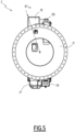
- a nuclear installation 1 is shown in the figure 1 in a simplified way.
- the nuclear installation 1 comprises an enclosure 11 which delimits an interior volume V1 of waterproof way.
- the enclosure 11 is for example the enclosure of a nuclear reactor, or a containment box.
- the sealed enclosure 11 is the enclosure protecting the core of the reactor of a nuclear power station using Natural Uranium Graphite Gas (UNGG).
- UUG Natural Uranium Graphite Gas
- several stacks 13 of graphite bricks are arranged in the interior volume V1 of the enclosure 11, most of the graphite bricks being pierced with a central duct which can accommodate a fuel cartridge or a rod of control.
- the interior volume V1 of the enclosure 11 is therefore subjected to significant radioactive activity, in the form of ionizing radiation and in the form of contamination, such as dust and radioactive materials, for example.
- a dismantling system 2 is also represented at the figure 1 .
- the dismantling system 2 is used inside the nuclear installation 1 when an intervention, in particular dismantling, is carried out.
- the nuclear installation 1 and part of the dismantling system 2 are shown in section along a plane comprising a vertical axis Z.
- top In the rest of the description, the terms “top”, “bottom”, “upper”, “lower”, “up” and “down” are understood by referring to the vertical axis Z.
- orientation “horizontal” refers to an orientation orthogonal to the vertical Z axis.
- two orthogonal axes are two axes each being perpendicular to a third axis.
- two orthogonal axes are not necessarily secant.
- Two orthogonal and intersecting axes are perpendicular.
- the dismantling system 2 makes it possible to handle the graphite bricks so as to evacuate them from the stacks 13.
- the dismantling system 2 comprises a fixed part 3, a mast 4, a handling system 5, a tool 6 suitable for handling the graphite bricks and a robotic arm 7, fixed to the mast 4 and carrying the tool 6.
- the fixed part, the mast and the handling system are shown in section in the figure 1 , while the robotic arm and the tool are shown in side view.
- the dismantling system 2 rests on the enclosure 11 of the nuclear installation 1, via its fixed part 3.
- the fixed part 3 comprises a base 31 and a guide cylinder 33 which extends along the vertical axis Z through an opening 15 made in the enclosure 11 and opening into the interior volume V1.
- the opening 15 is circular.
- the base 31 is therefore located outside the enclosure 11, that is to say outside the interior volume V1.
- the fixed part 3 carries the mast 4, which extends downwards, that is to say towards the inside of the enclosure 11.
- the mast 4 is substantially vertical, and therefore extends along the axis vertical Z, which is a main axis of the dismantling system 2.
- the mast 4 thus comprises an upper end 41 and a lower end 43, and the mast is carried by the fixed part 3 at its upper end 41.
- the mast 4 s extends through the opening 15.
- the mast 4 is formed of several modules 45, juxtaposed along the vertical axis Z, and assembled together, for example by clamping.
- the mast 4 comprises four modules 45.
- the guide cylinder 33 comprises guide pads 35, which are in contact with the modules 45 so as to center the mast 4 in the guide cylinder.
- the guide cylinder comprises nine guide pads 35, divided into three groups of three guide pads, the three guide pads of each group being distributed along the guide cylinder along the vertical axis Z and the three groups being regularly distributed all around the guide cylinder.
- the handling system 5, arranged entirely outside the enclosure 11, makes it possible to raise and lower the mast 4 relative to the fixed part 3.
- the handling system 5 comprises a lifting beam 51, connected to lifting means not shown, such as for example a crane or an overhead crane.
- the lifter 51 is therefore movable outside the enclosure 11 using the lifting means.
- the lifter 51 is adapted to be connected to the upper end 41 of the mast 4, by means of a handling flange 53.
- the handling flange 53 can also be separated from the mast 4, to separate the movement of the rudder from the movement of the mast.
- the handling system 5 also comprises actuators 55, for example jacks, on which the lifter 51 rests, and which allow the lifter to be moved between a high position and a low position.
- a high position and a low position of the mast 4 are also defined, which is movable in translation along the Z axis in the guide cylinder 33, that is to say inside the guide cylinder.
- the spreader bar is connected to the mast 4 and in the high position, then the mast is in the high position.
- the lifter is connected to the mast 4 and in the low position, then the mast is in the low position.
- the guide cylinder 33 and the mast 4 are straight circular cylinders.
- the guide cylinder has an internal diameter, denoted "D33”, of between 200 mm and 3000 mm, preferably equal to 2400 mm.
- the mast 4 has an outside diameter, denoted "D4", of between 1300 mm and 2300 mm, preferably equal to 1700 mm.
- the dismantling system 2 therefore has an annular space 37, formed between the guide cylinder 33 and the mast 4.
- the guide pads 35 are arranged in the annular space 37.
- the dismantling system 2 advantageously comprises a plug 39, which closes the annular space 37.
- Mast 4 is modular, that is to say it is possible to vary the number of modules 45 that the mast comprises. Thus, it is possible, using the handling system 5, to add or remove modules 45 from the mast 4. For example, to add a module, the mast is lowered to the low position, then an additional module is attached to the upper end 41 of the mast. To remove a module, the mast is mounted in the high position, then the highest module of the mast is separated from the mast and evacuated.
- the modular aspect of the mast 4 and the handling system 5 it is possible to modify the height of the mast 4, denoted "H4", and thus the position of the lower end 43 of the mast inside the volume V1 of the enclosure 11.
- the modules 45 have a height of approximately 1200 mm, and the mast 4 can comprise between 3 and 15 modules.
- the height H4 of the mast can vary between 3600 mm and 18000 mm.
- the tool 6 is carried by the robotic arm 7, itself fixed to the lower end 43 of the mast 4.
- the robotic arm 7 makes it possible to move and orient the tool 6 within the volume V1, in order to that the tool can carry out the operations necessary for the dismantling of the nuclear installation 1.
- the tool 6 can be positioned using the robotic arm 7, which serves as a mobile support for it.
- the robotic arm 7 and the tool 6 are entirely placed in the volume V1, when the dismantling system 2 is put in place in the nuclear installation 1.
- the tool 6 is for example suitable for handling the bricks of the stacks 13.
- the tool 6 is shown only in figure 1 And 9 .
- the tool 6 is for example a gripper.
- the robotic arm 7 is shown in more detail in figures 2 to 9 .
- the robotic arm is a poly-articulated arm with seven degrees of freedom, that is to say a multi-axis robot, which therefore makes it possible to position the tool 6 according to any desired configuration within the volume V1 of the enclosure 11 .
- the robotic arm 7 comprises, in the following order and from the lower end 43 of the mast 4 to the tool 6, a base 71, a slewing ring 73, an extension member 75, a main member 77, a telescopic member 79, an end member 81 and a rotating head 83.
- the robotic arm 7 is supported by the base 71, which is fixed to the lower end 43 of the mast 4.
- the base 71 is fixed at the bottom of the lowest module 45 of the mast, for example by clamping.
- the base 71 supports the tool 6, via the slewing ring 73, the members 75, 77, 79 and 81 and the rotating head 83, the latter forming the end of the robotic arm.
- the base is a machine-welded cylindrical part having an assembly flange intended to be screwed to the lower end 43 of the mast 4 and whose diameter is equal to the diameter D4.
- the slewing ring 73 is supported by the base 71, being articulated in a motorized manner with respect to the base 71 via a drive system 731, pivoting here in yaw.
- the slewing ring 73 is rotatable relative to the base 71 around a vertical axis Z73, which advantageously coincides with the vertical axis Z, being driven by the drive system 731
- the slewing ring 73 therefore allows rotation of the whole of the robotic arm 7, apart from the base 71, with respect to the mast 4.
- the rotation of the slewing ring 73 with respect to the base 71 forms a first degree freedom of the robotic arm 7.
- the drive system 731 comprises a toothed wheel 733, fixed relative to the slewing ring 73 and which surrounds the slewing ring, and an actuator 735, fixed to the base 71.
- the actuator 735 comprises a meshing element 737, which is provided to cooperate with the toothed wheel 733 to drive the rotation of the toothed wheel.
- the meshing element 737 is a pinion whose rotation is controlled by the actuator 735.
- the actuator 735 is a motor, such as for example a hydraulic motor or an electric motor.
- actuator 735 is a rotary hydraulic cylinder.
- the actuator 735 is fixed and integrated into a fixed part of the slewing ring 73, rather than being fixed to the base 71.
- the drive system 731 allows unlimited rotation, that is to say unlimited movement, of the slewing ring 73 relative to the base 71 around the axis Z73.
- the toothed wheel 733 does not include a stop.
- the rotation of the robotic arm 7 relative to the mast 4 around the axis Z73 is not limited by the slewing ring 73.
- the extension member 75 is supported by the slewing ring 73, being articulated in rotation with respect to the slewing ring about a pivot axis X75, pivoting in pitch.
- the pivot axis X75 is orthogonal to the axes Z and Z73, here being secant with them.
- the pivoting of the extension member 75 relative to the slewing ring 73 forms a second degree of freedom of the robotic arm 7.
- the pivoting of the extension member 75 is actuated by a linear actuator 751, of which a first end 751A is fixed to the slewing ring 73 and of which a second end 751B is fixed to the extension member.
- Actuator 751 is, in the example, a double-acting linear hydraulic cylinder. The displacement of the actuator 751 causes the pivoting, that is to say the rotation, of the extension member 75 relative to the slewing ring 73 around the pivot axis X75.
- L751 the stroke of the cylinder 751, that is to say the difference between the maximum length between the ends 751A and 751B when the cylinder is fully extended and the minimum length between ends 751A and 751B when the actuator is fully retracted.
- ⁇ 75 refers to the angular movement of the extension member 75, that is to say the difference between the angular position of the extension member 75 relative to the slewing ring 73 when the cylinder 751 is completely retracted, and the position angle of the extension member relative to the slewing ring when the actuator is fully extended.
- the main member 77 is supported by the extension member 75, being articulated in rotation with respect to the extension member around a pivot axis X77, pivoting in pitch.
- the X77 pivot axis is parallel to the X75 pivot axis and orthogonal to the Z and Z73 axes.
- the pivoting of the main member 77 relative to the extension member 75 forms a third degree of freedom of the robotic arm 7.
- the pivoting of the main member 77 is actuated by a linear actuator 771, of which a first end 771A is fixed to the extension member 75 and of which a second end 771B is fixed to the main member.
- Actuator 771 is, in the example, a double-acting linear hydraulic cylinder. The displacement of the actuator 771 causes the pivoting, that is to say the rotation, of the main member 77 with respect to the extension member 75 around the pivot axis X77.
- “L771” is the stroke of the cylinder 771, that is to say the difference between the maximum length between the ends 771A and 771B when the cylinder is fully extended and the minimum length between the ends 771A and 771B when the cylinder is completely retracted.
- Called “a77” the angular movement of the main member 77, that is to say the difference between the angular position of the main member 77 relative to the extension member 75 when the cylinder 771 is fully retracted, and the angular position of the member main relative to the extension member when the actuator is fully extended.
- the telescopic member 79 is supported by the main member 77, being articulated in rotation with respect to the main member around a pivot axis X79, pivoting in pitch.
- the X79 pivot axis is parallel to the X75 and X77 pivot axes and orthogonal to the Z and Z73 axes.
- the pivoting of the telescopic member 79 relative to the main member 77 forms a fourth degree of freedom of the robotic arm 7.
- the pivoting of the telescopic member 79 is actuated by a linear actuator 791, of which a first end 791A is fixed to the main member 77 and of which a second end 791B is fixed to the telescopic member.
- Actuator 791 is, in the example, a double-acting linear hydraulic cylinder. The displacement of the actuator 791 causes the pivoting, that is to say the rotation, of the telescopic member 79 with respect to the main member 77 around the pivot axis X79.
- the telescopic member 79 further comprises an inner part 793 and an outer part 795, movable in translation relative to each other in a moving away-approaching movement, that is to say in a sliding movement of the outer portion 795 around inner portion 793.
- telescopic member 79 can be retracted or extended.
- the translation of the telescopic member 79 forms a fifth degree of freedom of the robotic arm 7.
- the telescopic member comprises a linear actuator 797, of which a first end 797A is fixed to the inner part 793 and of which a second end 797B is fixed to the outer part 795.
- the actuator 797 is, in the example, a linear hydraulic cylinder double effect.
- the displacement of the actuator 797 causes the translation of the telescopic member 79 in the direction of the telescopic member, that is to say along a telescopic axis Y79 corresponding to the axis along which the telescopic member extends.
- L797 the stroke of cylinder 797, that is to say the difference between the maximum length between ends 797A and 797B when the cylinder is fully extended and the minimum length between ends 797A and 797B when the cylinder is completely retracted.
- the inner part 793 is fixed to the main member 77.
- the inner part 793 is therefore fixed in translation along the telescopic axis Y79, and the outer part 795 is movable in translation along the along the telescopic axis Y79.
- the inner part 793 is fixed relative to the mast 4 and relative to the nuclear installation 1, and the outer part 795 is movable relative to the mast and relative to the nuclear installation.
- the second end 791B of the cylinder 791 is fixed to the inner part 793 of the telescopic member 79. More precisely, the second end 791B of the cylinder 791 is fixed to the base of the inner part 793, so as not to block the translation of the outer part 795, that is to say not to prevent the retraction movement of the telescopic member 79.
- the end member 81 is supported by the telescopic member 79, being articulated in rotation with respect to the telescopic member around a pivot axis X81, pivoting in pitch.
- the pivot axis X81 is parallel to the pivot axes X75, X77 and X79 and orthogonal to the Z and Z73 axes.
- the pivoting of the end member 81 relative to the telescopic member 79 forms a sixth degree of freedom of the robotic arm 7.
- the pivoting of the end member 81 is actuated by a linear actuator 811, of which a first end 811A is fixed to the telescopic member 79, more precisely to the outer part 795 of the telescopic member, and of which a second end 811B is fixed to the 'end.
- the actuator 811 is, in the example, a double-acting linear hydraulic cylinder. The displacement of the actuator 811 causes the pivoting, that is to say the rotation, of the end member 81 relative to the telescopic member 79 around the pivot axis X81.
- L811 is the stroke of cylinder 811, i.e. the difference between the maximum length between ends 811A and 811B when the cylinder is fully extended and the minimum length between ends 811A and 811B when the cylinder is completely retracted.
- ⁇ 81 refers to the angular displacement of the end member 81, that is to say the difference between the angular position of the end member 81 relative to the telescopic member 79 when the jack 811 is completely retracted, and the angular position of the end member relative to the telescopic member when the cylinder is fully extended.
- the end member 81 comprises an end portion 813, a first connecting rod 815 and a second connecting rod 817.
- the end portion 813 is pivotally articulated relative to the telescopic member 79 around the pivot axis X81 .
- the first connecting rod 815 is articulated in pivoting on the one hand with respect to the end portion 813, around a pivot axis X813, and on the other hand with respect to the second connecting rod 815, around a X'813 swivel.
- the second connecting rod 817 is also pivotally articulated relative to the telescopic member 79, around a pivot axis X815, and pivotally articulated relative to the second end 811B of the hydraulic cylinder 811, around a pivot axis X '815.
- the end portion 813, the first connecting rod 815 and the second connecting rod 817 together form an articulated system having the advantage of amplifying the pivoting of the end member relative to the telescopic member when the actuator 811 is actuated.
- the angular displacement a81 of the end member 81 is increased, compared to a robotic arm in which the end member would not include connecting rods and in which the second end 811B of the jack 811 would be connected to end portion 813.
- the inner part 793 of the telescopic member 79 is fixed to the main member 77, for the outer part 795 of the telescopic member to be mobile and for the first end 811A of the cylinder 811 to be fixed to the outer part, opposite prejudices in the field according to which the outer part of a telescopic member is fixed and the inner part of a telescopic member is mobile, because this allows the cylinder 811 to have a sufficient length so that its stroke L811 allows the member to end 81 to have good mobility, that is to say a significant clearance a81.
- the cylinder 811 should be shortened, to be able to be fixed at the end of the inner part 793 remaining accessible when the inner part is retracted into the outer part.
- the stroke L811 would then be reduced, which would also reduce the clearance a81 of the end member 81.
- the rotary head 83 on which the tool 6 is fixed, is supported by the end member 81, being articulated in rotation with respect to the end member, here pivoting in roll.
- the rotary head 83 and the tool 6 are rotatable relative to the end member 81 around a head axis Y83 orthogonal with the pivot axis X81.
- the rotation of the rotating head relative to the end member 81 forms a seventh degree of freedom of the robotic arm 7.
- the rotation of the rotary head 83 is actuated by a rotary actuator 831, disposed in the end member 81.
- the actuator 831 is, in the example, a rotary hydraulic cylinder. Rotation of actuator 831 causes rotary head 83 to rotate relative to end member 81 around axis of rotation Y83.
- the actuator 831 is a rack and pinion actuator, in which the translation of a piston causes the translation of a rack, which causes the rotation of a pinion.
- the cylinder 831 is another type of rotary cylinder, such as for example a helical cylinder.
- the rotary actuator 831 allows a rotation, that is to say a displacement, of the rotary head 83 with respect to the end member 81 around the axis of the head Y83 greater than or equal to 180°, preferably equal to 360°.
- the tool 6 carried by the rotary head 83 can take all the orientations required to perform dismantling operations.
- the displacement of the rotary actuator 831 is smaller, for example 90°, which makes it possible to lighten the actuator 831, so as to improve the compactness of the robotic arm 7.
- the rotary head 83 comprises a tool changer which allows the tool 6 attached to the robotic arm 7 to be changed, choosing from a group of available tools.
- a tool changer which allows the tool 6 attached to the robotic arm 7 to be changed, choosing from a group of available tools.
- the cylinders 751, 771, 791, 797, 811 and 831 and possibly the motor 735, are supplied with oil by a hydraulic unit 85.
- the hydraulic unit is remote from the robotic arm 7 so as to be located outside of the waterproof enclosure.
- the hydraulic unit 85 is fixed to the fixed part 3 of the dismantling system 2.
- the jacks and possibly the motor are connected to the hydraulic unit 85 by flexible hoses 86, which extend from the exterior of the enclosure 11 to the volume V1 passing through the annular space 37 formed between the mast 4 and the guide cylinder 3.
- the hydraulic unit 85 is shown in a simplified manner, and a single hose 86, connecting the motor 735 to the hydraulic unit, is shown.
- motor 735 is a hydraulic motor. It is advantageous for the hydraulic unit 85 to be arranged outside the volume V1, because this allows the hydraulic unit not to be exposed to the significant radioactive activity prevailing in the volume V1 in the form of ionizing radiation and in the form of contaminations. Similarly, it is also advantageous for the cylinders 751, 771, 791, 797, 811 and 831 and possibly the motor 735 to be hydraulic, since the hydraulic mechanisms are not sensitive to ionizing radiation, and therefore less likely to suffer breakdowns, unlike electric mechanisms, such as for example electric cylinders. Thus, the service life of the hydraulic unit and the cylinders are improved, which makes it possible to make the operation of the robotic arm 7 more reliable.
- the hoses 86 are also advantageous for the hoses 86 to extend between the mast 4 and the guide cylinder 3, because the flexibles thus extend in the same opening 15 as the guide cylinder 33 and as the mast 4, which facilitates the control of the tightness of the enclosure 11, since the flexibles do not require the presence of a another opening in the enclosure.
- the plug 39 is adapted to allow the passage of the hoses 86 without breaking the seal of the enclosure 11.
- Table 1 lists the stroke of the linear actuators of the robotic arm 7.
- Cylinder reference L751 L771 L791 L797 L811 Useful stroke 650mm 750mm 550mm 650mm 550mm Travel reference ⁇ 75 ⁇ 77 ⁇ 79 ⁇ 81 Maximum travel 68° 74° 85° 105°
- the robotic arm 7 is particularly advantageous, if its seven degrees of freedom allow it to occupy multiple different configurations, which confers very high mobility on the tool 6.
- the robotic arm 7 is shown in a folded configuration, which is particularly compact both horizontally and vertically.
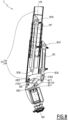
- the robotic arm is shown in an unfolded configuration, which gives the robotic arm a particularly large downward extension.
- the robotic arm is shown in an extended configuration, which allows the tool 6 carried by the robotic arm to reach objects that are particularly distant from the mast 4, horizontally.
- the vertical size of the robotic arm 7 is called "H7", that is to say the largest vertical dimension of the robotic arm, measured along the vertical axis Z between the top of the base 71 and the lowest point of the robotic arm.
- R7 the horizontal dimension of the robotic arm, that is to say the largest radial dimension of the robotic arm, measured in a plane perpendicular to the vertical axis Z between the vertical axis and the point of the arm robot farthest from the vertical axis.
- the extension member 75, the main member 77 and the telescopic member 79 are moved closer together, so as to form a "Z", and the telescopic member is retracted.
- This configuration makes it possible to minimize the vertical bulk H7 and the horizontal bulk R7 of the robotic arm.
- H7 min the minimum vertical bulk
- R7 min the minimum horizontal bulk of the robotic arm.
- the cylinders 751, 771, 791 and 797 are completely retracted.
- This folded configuration of the robotic arm 7 is particularly advantageous for simultaneously reducing its horizontal size and its vertical size.
- the end member 81 is raised, so as to be as close as possible to the main member 77.
- the jack 811 is completely extended.
- the space requirement H7 min is between 3000 mm and 5000 mm, preferably equal to 4000 mm, and the space requirement R7 min is between 950 mm and 1450 mm, preferably equal to 1100 mm .
- the extension member 75, the main member 77 and the telescopic member 79 are positioned so as to maximize the greatest vertical dimension H7 of the robotic arm 7.
- H7 max the maximum vertical size of the robotic arm .
- jack 751 is completely retracted, jacks 771 and 797 and 791 are fully extended.
- This unfolded configuration is particularly advantageous for allowing the tool 6 to reach objects located particularly far from the lower end 43 of the mast 4.
- the cylinder 811 is also shown fully retracted, but the position of the cylinder 811 is in practice adapted to the desired pivoting orientation for the tool 6.
- the vertical size H7 max of the robotic arm 7 corresponds to the vertical extension of the robotic arm, that is to say the vertical distance at which the tool 6 is located from the base 71, and therefore the maximum vertical working distance of the tool.
- the presence of the telescopic member 79 is particularly advantageous for increasing the vertical extension of the robotic arm, without increasing its bulk in the folded configuration.
- the size H7 max is between 7000 mm and 9000 mm, preferably equal to 8200 mm.
- the robotic arm 7 is capable of supporting a mass of approximately 1700 kg, corresponding in practice to the sum of the mass of the tool 6 and the mass of the load carried by the tool.
- the extension member 75, the main member 77 and the telescopic member 79 are positioned so as to maximize the greatest horizontal dimension R7 max of the robotic arm 7 while allowing the tool 6 to carry a heavy load.
- the cylinders 751, 771 and 791 are in an intermediate position between their retracted position and their extended position. The intermediate position of the cylinders 751, 771 and 791 is determined so as to simultaneously maximize the mass that can be supported by the robotic arm and the greatest horizontal dimension R7 max .
- the telescopic member 79 is further retracted, i.e. the jack 797 is fully retracted.
- the space requirement R7 max is between 4500 mm and 6500 mm, preferably equal to 5500 mm. Furthermore, the same size R7 max of the robotic arm 7 can be obtained with the telescopic member 79 partially or completely deployed, and with the cylinders 751, 771 and 791 in other intermediate positions between their retracted position and their deployed position than those represented at the figure 9 .
- the horizontal bulk R7 max of the robotic arm 7 corresponds to the horizontal extension of the robotic arm, that is to say the horizontal distance at which the tool 6 is located from the vertical axis 7, and therefore the maximum horizontal working distance of the tool.
- the robotic arm 7 is capable of supporting a mass of approximately 700 kg, corresponding in practice to the sum of the mass of the tool 6 and the mass of the load carried by the tool.
- the robotic arm 7 is capable of supporting a mass of approximately 1700 kg at a distance of 5000 mm, that is to say for the horizontal space R7 of the robotic arm equal to 5000 mm.
- the robotic arm 7 is therefore able to support high loads at long distances, which makes it particularly suitable for carrying out nuclear installation dismantling operations.
- the folded, unfolded, extension configurations as well as the intermediate configuration not shown are configurations in which the robotic arm 7 is able to support a particularly high mass, that is to say configurations in which the robotic arm is able to perform material handling tasks.
- the robotic arm 7 in these configurations, as well as in any intermediate configuration between two of these configurations, the robotic arm 7 is in handling condition.
- the robotic arm 7 is capable of supporting a mass of at least 700 kg regardless of its configuration, when it is in handling condition. The robotic arm 7 is therefore able to support heavy loads in multiple configurations.
- the extension and the mass that can be supported by the robotic arm are therefore particularly adaptable, depending on the operating constraints encountered by the robotic arm during the dismantling operations of the nuclear installation 1.
- the robotic arm 7 is thus able to adapt its vertical size and its horizontal size significantly, according to the conditions required by the dismantling operations carried out.
- the maximum vertical space H7 max of the robotic arm 7, reached in the unfolded configuration is greater than or equal to twice the minimum vertical space H7 min of the robotic arm, reached in the folded configuration.
- the maximum vertical space H7 max is equal to 2.05 times the minimum vertical space H7 min .
- These advantages come in particular from the combined use of four members pivoting between them, namely the extension 75, main 77, telescopic 79 and end 81 members, which makes it possible to give the robotic arm a "Z" shape when it is in the folded configuration, and has a telescopic member, which makes it possible to increase the extension of the robotic arm.
- the use of the slewing ring 73 and the rotary head 83 simultaneously makes it possible to adapt the orientation of the robotic arm 7 and of the tool 6, which makes it possible to adapt to all the needs of orientation that may be encountered during the dismantling of nuclear installation 1.
- the telescopic member 79 and the end member 81 are offset, along the pivot axis X79, from the extension member 75 and the main member 77.
- the telescopic member and the end member are aligned with each other along the axis X79
- the extension member and the main member are aligned with each other along the axis X79
- the telescopic member is offset from the main member along the axis X79 at the connection between the telescopic member and the main member.
- the telescopic member 79 comprises a fixing part 799, fixed to the inner part 793 while being offset from the inner part 793 along the axis X79, and to which the second end 791B of the jack 791 is fixed.
- cylinder 791 is aligned with main member 77, but offset from the telescopic member.
- This offset allows the telescopic member 79 to pivot on the main member side 77, without colliding with the main member.
- This design is in practice more compact than a design in which the telescopic member is aligned with the main member.
- the cylinder 751 is offset, along the axis X75, from the extension member 75, which makes it possible to reduce the size of the robotic arm 7 in the folded configuration, by allowing the cylinder 771 of the main member 77 to be housed in the extension member 75, as best seen at figure 2 And 3 .
- the robotic arm 7 is advantageously controlled remotely, from outside the enclosure 11.
- the robotic arm is either controlled manually by an operator, at the through an Interface Man-Machine (HMI), such as using joysticks, or automatically, such as by software.
- HMI Interface Man-Machine
- the robotic arm comprises a set of sensors 88, represented schematically in the figures.
- the slewing ring 73, the limbs 75, 77, 79 and 81 and the rotating head 83 each carry sensors 88, which are sensors making it possible to detect the position of the robotic arm 7, and making it possible to detect a collision between the robotic arm and its environment before it occurs, so as to avoid it.
- sensors 88 are sensors making it possible to detect the position of the robotic arm 7, and making it possible to detect a collision between the robotic arm and its environment before it occurs, so as to avoid it.
- These sensors are, for example, linear or angular position sensors, speed sensors, acceleration sensors, sensors such as vision sensors, 3D scanners, or even temperature, pressure or radiation measurement sensors. These sensors preferably provide real-time data.
- the sensors 88 are for example applied on the slewing ring, the limbs and the rotary head. Sensors 88 are shown only at picture 3 , schematically.
- the data coming from the sensors 88 are analyzed by electronic cards 89, represented only at the figure 1 schematically.
- the electronic cards 89 are offset from the robotic arm 7 so as to be located outside the sealed enclosure 11.
- the electronic cards 89 are fixed to the fixed part 3 of the dismantling system 2.
- the electronic cards 89 are not subjected to the ionizing radiation present in the sealed enclosure 11, which could, otherwise, compromise their operation and lead to failures.
- the operation of the sensors 88 is thus made more reliable, which makes it possible to reduce the risks of loss of information concerning the position of the robotic arm 7.
- the data analyzed by the electronic cards 89 are used to correct the commands sent to the hydraulic unit 85 controlling the cylinders and to the motor 735, so that the commanded position of the robotic arm 7 is permanently controlled with precision and taking into account the real position of the robotic arm, and so as to avoid a collision between the robotic arm and its environment.
- the sensors 88 detect that a part of the robotic arm 7, such as the rotating head 83, is following a trajectory that could lead to a collision, such as for example with a stack 13 or with the enclosure 11, then the data analyzed by the electronic cards 89 make it possible to correct the commands sent to the hydraulic unit 85 so as to avoid this collision.
- the sensors 88 also make it possible to prevent certain members of the robotic arm 7 from colliding with other parts of the robotic arm, in particular when the robotic arm is in the folded configuration. Indeed, in this configuration, the great compactness of the robotic arm 7 leads to the fact that certain pivoting of the limbs 75, 77, 79 and 81 could lead to their collision with other parts of the robotic arm. For example, the main member 77 could collide with the base 71 if the extension member 75 were pivoted by deploying the cylinder 751.
- the presence of the sensors 88 makes it possible to detect the imminence of such a collision before it occurs. , and the analysis carried out by the electronic cards 89 of the data coming from the sensors makes it possible to correct the movement of the robotic arm 7 to avoid such a collision.
- the dismantling system 2 also comprises one or more cameras 90 arranged for example on the base 71 and/or on the rotating head 83.
- the cameras 90 make it possible to monitor the dismantling operations carried out by the robotic arm 7 and the tool 6.
- the cameras 90 also make it possible to locate the position of the stacks 13 of graphite bricks inside the enclosure 11, as well as the relative position of the robotic arm and of the tool with respect to the stacks, which makes it possible to provide data making it possible to adapt the commands of the jacks 751, 771, 791, 797, 811 and 831 and of the motor 735 controlling the position of the robotic arm 7 in the enclosure 11.
- Positioning a camera 90 on the rotary head 83 is particularly advantageous, because this makes it possible to control with precision the operations carried out by the tool 6 and the position of the stacks 13.
- the cameras 90 are represented only on the figure 2 , schematically.
- the images produced by the cameras 90 are analyzed, for example by the electronic cards 89, or by software, in order to automatically recognize the position of the elements to be manipulated by the robotic arm 7 , that is to say, in the example, stacks 13 of graphite brick, as well as the relative position of the robotic arm 7 and of the tool 6 with respect to the elements to be handled.
- This analysis of the images from the cameras 90 by the electronic cards 89 is preferably based at least on a recognition of shape and dimensions, this recognition preferably relying on image sensors incorporated in the cameras 90. , on the basis of this analysis, and on the basis of the knowledge of the position and the movements of the robotic arm 7 resulting from the analysis of the data of the sensors 88, the electronic cards 89 or the software are able to determine the movements and trajectory of the robotic arm.
- the electronic cards 89 or the software are also able to decide automatically on a change of tool if the tool changer of the rotary head 83 has, among the group of tools available, a tool more suitable for the needs than that fixed at the end of the robotic arm, for example a tool more suitable for handling the elements to be handled.
- the decision to change a tool is made by an operator located outside the enclosure 11, on the basis of data supplied by the electronic cards 89 or the software.
- the shape recognition carried out by the electronic cards 89 or the software is preferably carried out on the analysis of images produced by a contour detection algorithm, these images being for example black and white images in which the contours of the Objects within the image frame appear white, while non-outlined surfaces appear black.
- shape recognition can advantageously be performed on certain predefined areas of the image.
- the automation of the control of the robotic arm 7 is particularly reliable, because the knowledge of the position of the robotic arm 7 and the choice of the movements carried out by the robotic arm is carried out both on based on the data from the sensors 88 and on the basis of the images produced by the cameras 90.
- the data from the sensors 88 and the images produced by the cameras 90 are thus complementary to allow precise and reliable automatic control of the robotic arm 7.
- the operation of the dismantling system 2 is thus improved.
- a second embodiment of the dismantling system 2 will now be described, with reference to the figure 10 .
- elements similar to those of the first embodiment bear the same references and operate in the same way. If a reference is used in the description of the second embodiment without being reproduced in the corresponding figure, it corresponds to the part or piece bearing the same reference in the first embodiment. In the following, the differences between the second embodiment and the first embodiment are mainly described.
- the drive system 731 comprises a toothed wheel 733, identical to the toothed wheel of the first embodiment, and two actuators 735 each comprising a meshing element 737.
- the actuators 735 are for example hydraulic or electric motors, or rotary hydraulic cylinders.
- one of the two actuators 735 is hidden by the base 71, and only its meshing element 737 is visible.
- the meshing elements 737 are here endless screws, the rotations of which are controlled by the actuators 735, and which cause the rotation of the toothed wheel 733.
- the endless screws extend along an axis perpendicular to the axis of rotation Z73 of the slewing ring 73.
- An advantage of the second embodiment is to allow the reduction of the vertical size of the base 71.
- the actuators 735 extend in the extension of the endless screws 737, that is to say perpendicular to the vertical axis Z, and their vertical bulk is smaller than the actuators 735 of the first embodiment, which extend along the vertical axis Z and which therefore require that the base 71 is high enough to accommodate them.
- the base 71 is lower than in the first embodiment, which makes it possible to reduce the minimum vertical space H7min of the robotic arm 7. In the example, the space is reduced by about 200 mm, compared to the first embodiment.
- the drive system 731 comprises a single actuator 735 and therefore a single meshing element 737.
- a third embodiment of the dismantling system 2 will now be described, with reference to the figure 11 .
- elements similar to those of the first and second embodiments bear the same references and operate in the same way. If a reference is used in the description of the third embodiment without being reproduced in the corresponding figure, it corresponds to the part or piece bearing the same reference in the first or second embodiment. In the following, the differences between the third embodiment and the first and second embodiments are mainly described.
- the robotic arm 7 differs from the first embodiment.
- the robotic arm 7 has eight degrees of freedom.
- the end member 81 further comprises a rotary actuator 819.
- the rotary actuator 819 is, in the example, a rotary hydraulic cylinder.
- the rotary actuator 819 is disposed between the end portion 813 of the end member and the rotary actuator 831 rotating the rotary head 83.
- the rotation of the actuator 819 causes the rotation of the actuator 831 and of the rotary head 83 with respect to the end portion 813 around an axis of rotation Z81 orthogonal with the pivot axis X81 and with the head axis Y83 .
- the axis of rotation Z81 belongs to a plane containing the vertical axis Z
- the eighth degree of freedom formed by the rotary actuator 819 is particularly advantageous for improving the mobility of the robotic arm 7, since it allows the tool 6 fixed to the rotary head 83 to assume an orientation in which the head axis Y83 n does not belong to a plane containing the vertical axis Z.
- the tool 6 is able to work on elements not facing the mast 4 and the robotic arm 7, that is to say belonging to a plane not containing the vertical axis Z.
- the scope of action of the robotic arm 7 and of the tool 6 is thus extended to offset elements, in particular angularly, of the mast 4, which improves the mobility of the robotic arm and the performance of the dismantling system 2.
- the axis of rotation Z81 is thus referred to as an offset axis, and the rotary actuator 819 as an offset rotary actuator.
- the rotary offset cylinder making it possible to obtain the eighth degree of freedom of the robotic arm 7 does not belong to the end member 81, but belongs to one of the other members 75, 77 or 79.
- the rotary actuator belongs to the telescopic member 79 and is disposed between the outer part 795 of the telescopic member and the end member 81.
- the offset axis is orthogonal with pivot pins X75, X77, X79 and X81.
- the offset axis belongs to a plane containing the vertical axis Z.
- the eighth degree of freedom is not obtained with a rotary actuator, but with a pivoting movement of one of the members 75, 77, 79, 81 or of an additional member, around of a pivot axis orthogonal to the pivot axes X75, X77, X79, X81.
- the eighth degree of freedom of the robotic arm 7 is obtained by means other than a rotary offset actuator.
- the robotic arm 7 comprises an additional member, movable in rotation around a pivot axis parallel to the pivot axes X75, X77, X79 and X81, or even movable in translation, like the telescopic member 79.
- one of the four members 75, 77, 79 and 81 of the robotic arm 7 is furthermore mobile in rotation so as to be able to pivot in roll, in a manner similar to the rotary head 83, or the one of the extension 75, main 77 or end 81 members is also movable in translation, similarly to the telescopic member 79.
- the robotic arm 7 has more than eight degrees of freedom, for example nine degrees of freedom.
- the robotic arm comprises for example one or more additional members that can be moved in pivoting and/or in translation.
- the mast 4 is not modular, but of fixed height H4.
- the dismantling system 2 does not include a handling system 5.
- the raising and lowering of the mast 4, and therefore of the robotic arm 7 which is attached to it, are carried out for example at the using lifting means separate from the dismantling system, such as a traveling crane or a crane.
- the dismantling system 2 does not include a mast 4 distinct from the fixed part 3.
- the fixed part 3 comprises for example a base 31 and a mast fixed to the base.
- the dismantling system 2 rests on a rotating platform which itself rests on the enclosure 11.
- the fixed part 3 does not rest directly on the enclosure 11, but is connected to the enclosure 11 by the intermediary of the rotating platform.
- Such a rotating platform is mobile in rotation with respect to the enclosure 11 around a vertical axis parallel to the vertical axis Z, and not confused with the vertical axis Z.
- the rotation of the rotating platform causes the displacement of the fixed part 3, along an arc-de-circle, which causes the displacement of the mast 4, of the robotic arm 7 and of the tool 6.
- Such a rotating platform is particularly advantageous, because it makes it possible to move the whole of the robotic arm 7 within the enclosure 11, which makes it possible to increase the scope of action of the robotic arm 7, which is then greater than the greatest horizontal dimension R7 max of the robotic arm.
- extension 75, main 77, telescopic 79 and end 81 members is different.
- the telescopic member 79 is disposed between the extension member and the main member.
- the robotic arm 7 comprises on the one hand the orientation ring 73 and the rotary head 83 forming two of the seven degrees of freedom of the robotic arm, and on the other hand different members of the four members 75, 77, 79 and 81 to form the other five degrees of freedom of the robotic arm.
- the robotic arm 7 comprises an additional member, arranged between the member 79 and the member 81, which is pivotable in pitch with respect to the member 79, and the member 79 is not telescopic, that is to say that it is not mobile in translation, but only pivots in pitch with respect to the main member 77.
- the five degrees of freedom formed by the members of the robotic arm are then all pivoting degrees of freedom.
- the rotary head 83 is rotatable relative to the end member 81 while being pivotable in pitch, around an axis orthogonal to the pivot axis X81. In other words, in such a variant, the rotary head does not turn on itself but pivots relative to the end member.
Abstract
Ce système de démantèlement (2) pour une installation nucléaire (1) comprend une partie fixe (3) portant un mât (4) qui s'étend vers le bas, un bras robotisé (7), fixé à une extrémité basse du mât, et un outil (6), fixé au bras robotisé. Le bras robotisé est à sept degrés de liberté et comprend une couronne d'orientation (73), mobile en rotation et permettant une rotation du bras robotisé par rapport au mât, de sorte à former un des sept degrés de liberté, des membres (75, 77, 79, 81), mobiles par rapport à la couronne d'orientation et les uns par rapport aux autres, de sorte à former cinq des sept degrés de liberté, les membres comprenant un membre d'extrémité (81), et une tête rotative (83), montée sur le membre d'extrémité, portant l'outil et mobile en rotation par rapport au membre d'extrémité, de sorte à former un des sept degrés de liberté. En condition de manutention, le bras robotisé est conçu pour supporter une masse d'au moins 700 kg.This dismantling system (2) for a nuclear installation (1) comprises a fixed part (3) carrying a mast (4) which extends downwards, a robotic arm (7), fixed to a lower end of the mast, and a tool (6), attached to the robotic arm. The robotic arm has seven degrees of freedom and comprises an orientation ring (73), mobile in rotation and allowing rotation of the robotic arm relative to the mast, so as to form one of the seven degrees of freedom, limbs (75 , 77, 79, 81), movable relative to the slewing ring and relative to each other, so as to form five of the seven degrees of freedom, the members comprising an end member (81), and a rotary head (83), mounted on the end member, carrying the tool and rotatable relative to the end member, so as to form one of the seven degrees of freedom. In handling condition, the robotic arm is designed to support a mass of at least 700 kg.
Description
La présente invention concerne un système de démantèlement pour une installation nucléaire.The present invention relates to a dismantling system for a nuclear installation.
Les installations nucléaires, telles que par exemple les réacteurs Uranium Naturel Graphite Gaz (UNGG) comportent généralement une enceinte étanche comprenant du matériel radioactif, tel que du combustible nucléaire, par exemple sous forme de barres ou de briques. Ce matériel radioactif produit généralement un rayonnement ionisant important, ce qui empêche ou limite fortement la présence d'intervenants dans l'enceinte étanche. Les travaux de démantèlement de telles installations nucléaires sont donc dangereux, et il est donc courant d'utiliser des systèmes de démantèlement permettant d'effectuer de tels travaux de démantèlement sans intervention directe d'intervenants dans l'enceinte étanche. Ainsi, il est courant d'utiliser un bras robotisé pour effectuer des travaux de démantèlement, un tel bras robotisé étant contrôlé depuis l'extérieur de l'enceinte étanche.Nuclear installations, such as for example Natural Uranium Graphite Gas (UNGG) reactors generally comprise a sealed enclosure comprising radioactive material, such as nuclear fuel, for example in the form of rods or bricks. This radioactive material generally produces significant ionizing radiation, which prevents or greatly limits the presence of workers in the sealed enclosure. The dismantling work of such nuclear installations is therefore dangerous, and it is therefore common to use dismantling systems making it possible to carry out such dismantling work without the direct intervention of workers in the sealed enclosure. Thus, it is common to use a robotic arm to carry out dismantling work, such a robotic arm being controlled from outside the sealed enclosure.
Le document
Cependant, il n'existe pas de système de démantèlement comprenant un bras robotisé suffisamment performant pour effectuer toutes les tâches de démantèlement requises pour démanteler entièrement les installations nucléaires, et en particulier les réacteurs UNGG, dont les briques de combustibles sont particulièrement complexes à démanteler.However, there is no dismantling system comprising a robotic arm with sufficient performance to carry out all the dismantling tasks required to completely dismantle nuclear installations, and in particular UNGG reactors, whose fuel bricks are particularly complex to dismantle.
C'est à ce besoin qu'entend répondre l'invention en proposant un système de démantèlement plus performant.It is to this need that the invention intends to respond by proposing a more efficient dismantling system.
À cet effet, l'invention concerne un système de démantèlement pour une installation nucléaire, comprenant une partie fixe, configurée pour être reliée à l'installation nucléaire, un mât, comprenant une extrémité haute et une extrémité basse, l'extrémité haute étant portée par la partie fixe, le mât s'étendant selon un axe vertical depuis la partie fixe vers le bas, un bras robotisé, fixé à l'extrémité basse du mât, et un outil, fixé au bras robotisé. Le bras robotisé est à au moins sept degrés de liberté et comprend une couronne d'orientation, mobile en rotation par rapport au mât autour de l'axe vertical et permettant une rotation du bras robotisé par rapport au mât, de sorte à former un des sept degrés de liberté ; des membres, mobiles par rapport à la couronne d'orientation et les uns par rapport aux autres, de sorte à former cinq des sept degrés de liberté, les membres comprenant un membre d'extrémité ; et une tête rotative, montée sur le membre d'extrémité et portant l'outil, la tête rotative étant mobile en rotation par rapport au membre d'extrémité autour d'un axe de tête, de sorte à former un des sept degrés de liberté. De plus, lorsque le bras robotisé est en condition de manutention, le bras robotisé est conçu pour supporter une masse, portée par la tête rotative, d'au moins 700 kg.To this end, the invention relates to a dismantling system for a nuclear installation, comprising a fixed part, configured to be connected to the nuclear installation, a mast, comprising an upper end and a lower end, the upper end being carried by the fixed part, the mast extending along a vertical axis from the fixed part downwards, a robotic arm, fixed to the lower end of the mast, and a tool, fixed to the robotic arm. The robotic arm has at least seven degrees of freedom and comprises an orientation ring, rotatable relative to the mast around the vertical axis and allowing rotation of the robotic arm relative to the mast, so as to form one of the seven degrees of freedom; members, movable relative to the slewing ring and relative to each other, so as to form five of the seven degrees of freedom, the members comprising an end member; and a rotating head, mounted on the end member and carrying the tool, the rotating head being rotatable relative to the end member about a head axis, so as to form one of the seven degrees of freedom . Additionally, when the robotic arm is in handling condition, the robotic arm is designed to support a mass, carried by the rotating head, of at least 700 kg.
Grâce à l'invention, le système de démantèlement comprend un bras robotisé proposant un nombre important de degrés de liberté, et dont les articulations sont particulièrement adaptées aux travaux de démantèlement requis dans une installation nucléaire, permettant ainsi d'améliorer la mobilité du bras robotisé et donc les performances du système de démantèlement.Thanks to the invention, the dismantling system comprises a robotic arm offering a large number of degrees of freedom, and whose joints are particularly suited to the dismantling work required in a nuclear installation, thus making it possible to improve the mobility of the robotic arm and therefore the performance of the dismantling system.
Selon des aspects avantageux, mais non obligatoires de l'invention, le système de démantèlement incorpore une ou plusieurs des caractéristiques suivantes, prises isolément ou selon toutes combinaisons techniquement admissibles :
- Lesdits membres sont constitués de quatre membres, les quatre membres étant mobiles en pivotement par rapport à la couronne d'orientation et les uns par rapport aux autres, autour d'axes de pivotement respectifs qui sont orthogonaux à l'axe vertical, les quatre membres comprenant un membre télescopique, distinct du membre d'extrémité et également mobile en translation le long d'un axe de translation.
- Le bras robotisé comprend, dans l'ordre suivant, depuis le mât jusqu'à l'outil :
- ∘ un socle, fixé à l'extrémité basse du mât ;
- ∘ la couronne d'orientation, mobile en rotation par rapport au socle autour de l'axe vertical ;
- ∘ parmi les quatre membres, un membre prolongateur, mobile en pivotement par rapport à la couronne d'orientation autour d'un premier des axes de pivotement ;
- ∘ parmi les quatre membres, un membre principal, mobile en pivotement par rapport au membre prolongateur autour d'un deuxième des axes de pivotement ;
- ∘ le membre télescopique, mobile en pivotement par rapport au membre principal autour d'un troisième des axes de pivotement et mobile en translation le long de l'axe de translation ;
- ∘ le membre d'extrémité, mobile en pivotement par rapport au membre télescopique autour d'un quatrième des axes de pivotement ; et
- ∘ la tête rotative, mobile en rotation par rapport au membre d'extrémité autour de l'axe de tête.
- Les quatre membres sont actionnés en pivotement par des vérins hydrauliques linéaires à double effet et le membre télescopique est actionné en translation par un vérin hydraulique linéaire à double effet.
- Le mât est configuré pour s'étendre au travers d'une ouverture ménagée dans une enceinte étanche de l'installation nucléaire, le bras robotisé est configuré pour être situé dans un volume intérieur de l'enceinte étanche, et les vérins hydrauliques linéaires à double effet sont alimentés en huile par une centrale hydraulique déportée du bras robotisé et configurée pour être située à l'extérieur de l'enceinte étanche.
- La tête rotative est actionnée en rotation par un vérin hydraulique rotatif à double effet et le vérin hydraulique rotatif à double effet est alimenté en huile par la centrale hydraulique.
- Chacun des membres et la tête rotative embarquent des capteurs configurés pour détecter la position du bras robotisé en temps réel, et configurés pour éviter une éventuelle collision du bras robotisé avec son environnement, et le système de démantèlement comprend des cartes électroniques configurées pour analyser les données provenant des capteurs et déportées du bras robotisé, les cartes électroniques étant configurées pour être situées à l'extérieur de l'enceinte étanche.
- Le membre télescopique comprend une partie intérieure et une partie extérieure, la partie extérieure étant configurée pour coulisser autour de la partie intérieure, et, lors de la translation du membre télescopique, la partie intérieure est fixe en translation le long de l'axe de translation par rapport au mât et la partie extérieure est mobile en translation le long de l'axe de translation par rapport au mât.
- La couronne d'orientation a un débattement illimité autour de l'axe vertical et la tête rotative a un débattement supérieur ou égal à 180° autour de l'axe de tête.
- La couronne d'orientation comprend une roue dentée, le bras robotisé comprend un actionneur, fixe par rapport au mât, l'actionneur comprenant un élément d'engrainement configuré pour coopérer avec la roue dentée pour entraîner la rotation de la couronne d'orientation, et, de préférence, l'élément d'engrainement est un pignon ou une vis sans fin.
- Un encombrement vertical du bras robotisé dans une configuration dépliée est supérieur ou égal à deux fois un encombrement vertical du bras robotisé dans une configuration repliée, et un encombrement horizontal du bras robotisé dans une configuration d'extension est supérieur ou égal à deux fois un encombrement horizontal du bras robotisé dans la configuration repliée.
- Lorsque le bras robotisé est en configuration repliée, le membre prolongateur, le membre principal et le membre télescopique sont repliés les uns vers les autres de sorte à former un « Z », et le membre télescopique est rétracté.
- La partie fixe comprend un cylindre de guidage configuré pour centrer le mât par rapport à la partie fixe, le cylindre de guidage étant de forme cylindrique et centré sur l'axe vertical, et, lorsque le bras robotisé est dans la configuration repliée, l'encombrement horizontal du bras robotisé est inférieur à la moitié d'un diamètre intérieur du cylindre de guidage.
- Le bras robotisé est à au moins huit degrés de liberté.
- Le huitième degré de liberté du bras robotisé est obtenu par un membres parmi les quatre membres, qui est en outre mobile en rotation autour d'un axe de décalage orthogonal aux axes de pivotement des quatre membres, ou par un membre supplémentaire, mobile en rotation par rapport aux quatre membres, autour d'un axe de décalage orthogonal aux axes de pivotement des quatre membres.
- Said members consist of four members, the four members being movable in pivoting relative to the slewing ring and relative to each other, around respective pivot axes which are orthogonal to the vertical axis, the four members comprising a telescopic member, separate from the end member and also movable in translation along a translation axis.
- The robotic arm comprises, in the following order, from the mast to the tool:
- ∘ a base, fixed to the lower end of the mast;
- ∘ the slewing ring, mobile in rotation relative to the base around the vertical axis;
- ∘ among the four members, an extension member, movable in pivoting relative to the slewing ring around a first of the pivoting axes;
- ∘ among the four members, a main member, movable in pivoting relative to the extension member around a second of the pivot axes;
- ∘ the telescopic member, movable in pivoting relative to the main member around a third of the pivot axes and movable in translation along the translation axis;
- ∘ the end member, movable in pivoting relative to the telescopic member around a fourth of the pivot axes; And
- ∘ the rotating head, mobile in rotation relative to the end member around the head axis.
- The four limbs are pivotally actuated by double-acting linear hydraulic cylinders and the telescopic limb is translationally actuated by a double-acting linear hydraulic cylinder.
- The mast is configured to extend through an opening made in a sealed enclosure of the nuclear installation, the robotic arm is configured to be located in an interior volume of the sealed enclosure, and the double linear hydraulic cylinders effect are supplied with oil by a hydraulic unit remote from the robotic arm and configured to be located outside the sealed enclosure.
- The rotary head is driven in rotation by a double-acting rotary hydraulic cylinder and the double-acting rotary hydraulic cylinder is supplied with oil by the hydraulic unit.
- Each of the limbs and the rotating head carry sensors configured to detect the position of the robotic arm in real time, and configured to avoid a possible collision of the robotic arm with its environment, and the dismantling system includes electronic cards configured to analyze the data from the sensors and remote from the robotic arm, the electronic cards being configured to be located outside the sealed enclosure.
- The telescopic member includes an inner part and an outer part, the outer part being configured to slide around the inner part, and, during translation of the telescopic member, the inner part is fixed in translation along the axis of translation relative to the mast and the outer part is movable in translation along the axis of translation relative to the mast.
- The slewing ring has unlimited movement around the vertical axis and the rotary head has a movement greater than or equal to 180° around the head axis.
- The slewing ring comprises a toothed wheel, the robotic arm comprises an actuator, fixed relative to the mast, the actuator comprising a meshing element configured to cooperate with the toothed wheel to drive the rotation of the slewing ring, and, preferably, the meshing element is a pinion or a worm.
- A vertical footprint of the robotic arm in an unfolded configuration is greater than or equal to twice a vertical footprint of the robotic arm in a folded configuration, and a horizontal footprint of the robotic arm in an extended configuration is greater than or equal to twice a footprint horizontal of the robotic arm in the folded configuration.
- When the robotic arm is in the folded configuration, the extension member, the main member and the telescopic member are folded towards each other so as to form a "Z", and the telescopic member is retracted.
- The fixed part comprises a guide cylinder configured to center the mast with respect to the fixed part, the guide cylinder being cylindrical in shape and centered on the vertical axis, and, when the robotic arm is in the folded configuration, the clutter horizontal of the robotic arm is less than half of an inside diameter of the guide cylinder.
- The robotic arm has at least eight degrees of freedom.
- The eighth degree of freedom of the robotic arm is obtained by one of the four limbs, which is also rotatable around an offset axis orthogonal to the pivot axes of the four limbs, or by an additional limb, rotatable relative to the four limbs, around an offset axis orthogonal to the pivot axes of the four limbs.
L'invention sera mieux comprise et d'autres avantages de celle-ci apparaitront plus clairement à la lumière de la description qui va suivre d'un mode de réalisation d'un système de démantèlement donnée uniquement à titre d'exemple et faite en référence aux dessins dans lesquels :
- [
Fig. 1 ] Lafigure 1 est une vue de côté d'une installation nucléaire comprenant un système de démantèlement conforme à un premier mode de réalisation de l'invention, sur laquelle certains éléments sont représentés en coupe ; - [
Fig. 2 ] Lafigure 2 est une vue en perspective d'un bras robotisé appartenant au système de démantèlement de lafigure 1 , représenté dans une configuration repliée ; - [
Fig. 3 ] Lafigure 3 est une vue en perspective du bras robotisé de lafigure 2 , selon un autre angle ; - [
Fig. 4 ] Lafigure 4 est une vue de côté du bras robotisé desfigures 2 et3 ; - [
Fig. 5 ] Lafigure 5 est une vue de dessus du bras robotisé desfigures 2 à 4 ; - [
Fig. 6 ] Lafigure 6 est une vue de côté du bras robotisé desfigures 2 à 5 , représenté dans une configuration dépliée ; - [
Fig. 7 ] Lafigure 7 est une vue de côté du bras robotisé de lafigure 6 , selon un autre angle ; - [
Fig. 8 ] Lafigure 8 est une coupe du bras robotisé desfigures 6 et7 , selon le plan VIII de lafigure 7 ; - [
Fig. 9 ] Lafigure 9 est une vue de côté du bras robotisé desfigures 2 à 8 , représenté dans une configuration d'extension ; - [
Fig. 10 ] Lafigure 10 est une vue en perspective d'une partie d'un bras robotisé appartenant à un système de démantèlement conforme à un deuxième mode de réalisation ; et - [
Fig. 11 ] Lafigure 11 est une vue de côté d'une partie d'un bras robotisé appartenant à un système de démantèlement conforme à un troisième mode de réalisation.
- [
Fig. 1 ] Therefigure 1 is a side view of a nuclear installation comprising a dismantling system in accordance with a first embodiment of the invention, in which certain elements are shown in section; - [
Fig. 2 ] Therefigure 2 is a perspective view of a robotic arm belonging to the dismantling system of thefigure 1 , shown in a folded configuration; - [
Fig. 3 ] Therepicture 3 is a perspective view of the robotic arm of thepicture 2 , from another angle; - [
Fig. 4 ] Therefigure 4 is a side view of the robotic arm of thefigure 2 And3 ; - [
Fig. 5 ] Therefigure 5 is a top view of the robotic arm of thefigures 2 to 4 ; - [
Fig. 6 ] Therefigure 6 is a side view of the robotic arm of thefigures 2 to 5 , shown in an unfolded configuration; - [
Fig. 7 ] Therefigure 7 is a side view of the robotic arm of thefigure 6 , from another angle; - [
Fig. 8 ] Therefigure 8 is a section of the robotic arm of thefigure 6 And7 , according to plan VIII of thefigure 7 ; - [
Fig. 9 ] Therefigure 9 is a side view of the robotic arm of thefigures 2 to 8 , shown in an expanded configuration; - [
Fig. 10 ] Therefigure 10 is a perspective view of part of a robotic arm belonging to a dismantling system according to a second embodiment; And - [
Fig. 11 ] Therefigure 11 is a side view of part of a robotic arm belonging to a dismantling system according to a third embodiment.
Une installation nucléaire 1 est représentée à la
Un système de démantèlement 2 est également représenté à la
À la
Dans la suite de la description, les termes « haut », « bas », « supérieur », « inférieur », « monter » et « descendre » se comprennent en faisant référence à l'axe vertical Z. De plus, l'orientation « horizontale » fait référence à une orientation orthogonale à l'axe vertical Z.In the rest of the description, the terms "top", "bottom", "upper", "lower", "up" and "down" are understood by referring to the vertical axis Z. In addition, the orientation "horizontal" refers to an orientation orthogonal to the vertical Z axis.
De plus, dans la suite de la description, on entend que deux axes orthogonaux sont deux axes étant chacun perpendiculaire à un troisième axe. Ainsi, deux axes orthogonaux ne sont pas nécessairement sécants. Deux axes orthogonaux et sécants sont perpendiculaires.Moreover, in the remainder of the description, it is understood that two orthogonal axes are two axes each being perpendicular to a third axis. Thus, two orthogonal axes are not necessarily secant. Two orthogonal and intersecting axes are perpendicular.
Dans l'exemple, le système de démantèlement 2 permet de manipuler les briques de graphite de sorte à les évacuer des empilements 13. Pour cela, le système de démantèlement 2 comprend une partie fixe 3, un mât 4, un système de manutention 5, un outil 6 adapté pour manipuler les briques de graphite et un bras robotisé 7, fixé au mât 4 et portant l'outil 6. La partie fixe, le mât et le système de manutention sont représentés en coupe sur la
Le système de démantèlement 2 repose sur l'enceinte 11 de l'installation nucléaire 1, par l'intermédiaire de sa partie fixe 3. Avantageusement, la partie fixe 3 comprend une base 31 et un cylindre de guidage 33 qui s'étend selon l'axe vertical Z au travers d'une ouverture 15 ménagée dans l'enceinte 11 et débouchant dans le volume intérieur V1. De préférence, l'ouverture 15 est circulaire. La base 31 est donc située à l'extérieur de l'enceinte 11, c'est-à-dire en dehors du volume intérieur V1.The dismantling system 2 rests on the
La partie fixe 3 porte le mât 4, qui s'étend vers le bas, c'est-à-dire vers l'intérieur de l'enceinte 11. Le mât 4 est sensiblement vertical, et s'étend donc selon l'axe vertical Z, qui est un axe principal du système de démantèlement 2. Le mât 4 comprend ainsi une extrémité haute 41 et une extrémité basse 43, et le mât est porté par la partie fixe 3 au niveau de son extrémité haute 41. En pratique, le mât 4 s'étend au-travers de l'ouverture 15. Avantageusement, le mât 4 est formé de plusieurs modules 45, juxtaposés selon l'axe vertical Z, et assemblés entre eux, par exemple par bridage. Dans l'exemple de la
Le système de manutention 5, disposé entièrement en dehors de l'enceinte 11, permet de faire monter et de faire descendre le mât 4 par rapport à la partie fixe 3. Pour cela, le système de manutention 5 comprend un palonnier 51, relié à des moyens de levage non-représentés, tels que par exemple une grue ou un pont roulant. Le palonnier 51 est donc mobile à l'extérieur de l'enceinte 11 à l'aide des moyens de levage. En outre, le palonnier 51 est apte à être relié à l'extrémité haute 41 du mât 4, par l'intermédiaire d'une bride de manutention 53. La bride de manutention 53 peut également être séparée du mât 4, pour dissocier le mouvement du palonnier du mouvement du mât. Avantageusement, le système de manutention 5 comprend également des actionneurs 55, par exemple des vérins, sur lesquels reposent le palonnier 51, et qui permettent de déplacer le palonnier entre une position haute et une position basse. On définit également une position haute et une position basse du mât 4, qui est mobile en translation selon l'axe Z dans le cylindre de guidage 33, c'est-à-dire à l'intérieur du cylindre de guidage. Lorsque le palonnier est relié au mât 4 et en position haute, alors le mât est en position haute. De même, lorsque le palonnier est relié au mât 4 et en position basse, alors le mât est en position basse.The
Dans l'exemple, le cylindre de guidage 33 et le mât 4 sont des cylindres circulaires droits. Le cylindre de guidage a un diamètre intérieur, noté « D33 », compris entre 200 mm et 3000 mm, de préférence égal à 2400 mm. Le mât 4 a un diamètre extérieur, noté « D4 », compris entre 1300 mm et 2300 mm, de préférence égal à 1700 mm.In the example, the
Le système de démantèlement 2 présente donc un espace annulaire 37, formé entre le cylindre de guidage 33 et le mât 4. En pratique, les patins de guidage 35 sont disposés dans l'espace annulaire 37. Par ailleurs, pour conserver l'étanchéité de l'enceinte 11, le système de démantèlement 2 comprend avantageusement un bouchon 39, qui ferme l'espace annulaire 37.The dismantling system 2 therefore has an
Le mât 4 est modulaire, c'est-à-dire qu'il est possible de faire varier le nombre de modules 45 que le mât comprend. Ainsi, il est possible, à l'aide du système de manutention 5, d'ajouter ou de retirer des modules 45 au mât 4. Par exemple, pour ajouter un module, le mât est descendu en position basse, puis un module supplémentaire est fixé à l'extrémité haute 41 du mât. Pour retirer un module, le mât est monté en position haute, puis le module le plus haut du mât est séparé du mât et évacué.
Grâce à l'aspect modulaire du mât 4 et au système de manutention 5, il est possible de modifier la hauteur du mât 4, notée « H4 », et ainsi la position de l'extrémité basse 43 du mât à l'intérieur du volume V1 de l'enceinte 11. Dans l'exemple, les modules 45 ont une hauteur d'environ 1200 mm, et le mât 4 peut comprendre entre 3 et 15 modules. Ainsi, dans l'exemple, la hauteur H4 du mât peut varier entre 3600 mm et 18000 mm.Thanks to the modular aspect of the
L'outil 6 est porté par le bras robotisé 7, lui-même fixé à l'extrémité basse 43 du mât 4. Ainsi, le bras robotisé 7 permet de mouvoir et d'orienter l'outil 6 au sein du volume V1, afin que l'outil puisse effectuer des opérations nécessaires au démantèlement de l'installation nucléaire 1. Autrement dit, l'outil 6 est positionnable à l'aide du bras robotisé 7, qui lui sert de support mobile. Ainsi, le bras robotisé 7 et l'outil 6 sont entièrement disposés dans le volume V1, lorsque le système de démantèlement 2 est mis en place dans l'installation nucléaire 1.The
L'outil 6 est par exemple adapté pour manipuler les briques des empilements 13. L'outil 6 est représenté uniquement aux
Le bras robotisé 7 est représenté plus en détail aux
Le bras robotisé 7 comprend, dans l'ordre suivant et depuis l'extrémité basse 43 du mât 4 jusqu'à l'outil 6, un socle 71, une couronne d'orientation 73, un membre prolongateur 75, un membre principal 77, un membre télescopique 79, un membre d'extrémité 81 et une tête rotative 83.The robotic arm 7 comprises, in the following order and from the
Le bras robotisé 7 est supporté par le socle 71, qui est fixé à l'extrémité basse 43 du mât 4. Avantageusement, le socle 71 est fixé en bas du module 45 le plus bas du mât, par exemple par bridage. Le socle 71 supporte l'outil 6, via la couronne d'orientation 73, les membres 75, 77, 79 et 81 et la tête rotative 83, cette dernière formant l'extrémité du bras robotisé. Dans l'exemple, le socle est une pièce cylindrique mécanosoudée présentant une bride d'assemblage prévue pour être vissée à l'extrémité basse 43 du mât 4 et dont le diamètre est égal au diamètre D4.The robotic arm 7 is supported by the
La couronne d'orientation 73 est supportée par le socle 71, en étant articulée de façon motorisée par rapport au socle 71 via un système d'entraînement 731, pivotant ici en lacet. En d'autres termes, la couronne d'orientation 73 est mobile en rotation par rapport au socle 71 autour d'un axe vertical Z73, qui est avantageusement confondu avec l'axe vertical Z, en étant entraînée par le système d'entraînement 731. La couronne d'orientation 73 permet donc une rotation de l'ensemble du bras robotisé 7, socle 71 mis à part, par rapport au mât 4. La rotation de la couronne d'orientation 73 par rapport au socle 71 forme un premier degré de liberté du bras robotisé 7.The slewing
Dans l'exemple des figures, le système d'entraînement 731 comprend une roue dentée 733, fixe par rapport à la couronne d'orientation 73 et qui entoure la couronne d'orientation, et un actionneur 735, fixé sur le socle 71. L'actionneur 735 comprend un élément d'engrainement 737, qui est prévu pour coopérer avec la roue dentée 733 pour entraîner la rotation de la roue dentée. Dans l'exemple, l'élément d'engrainement 737 est un pignon dont la rotation est commandée par l'actionneur 735. Dans l'exemple, l'actionneur 735 est un moteur, comme par exemple un moteur hydraulique ou un moteur électrique. En variante, l'actionneur 735 est un vérin hydraulique rotatif. En variante, l'actionneur 735 est fixé et intégré à une partie fixe de la couronne d'orientation 73, plutôt que d'être fixé au socle 71.In the example of the figures, the
Avantageusement, le système d'entraînement 731 permet une rotation illimitée, c'est-à-dire un débattement illimité, de la couronne d'orientation 73 par rapport au socle 71 autour de l'axe Z73. En pratique, la roue dentée 733 ne comprend pas de butée. Ainsi, la rotation du bras robotisé 7 par rapport au mât 4 autour de l'axe Z73 n'est pas limitée par la couronne d'orientation 73.Advantageously, the
Le membre prolongateur 75 est supporté par la couronne d'orientation 73, en étant articulé en rotation par rapport à la couronne d'orientation autour d'un axe de pivotement X75, pivotant en tangage. L'axe de pivotement X75 est orthogonal aux axes Z et Z73, en étant ici sécant avec eux. Le pivotement du membre prolongateur 75 par rapport à la couronne d'orientation 73 forme un deuxième degré de liberté du bras robotisé 7.The
Le pivotement du membre prolongateur 75 est actionné par un actionneur linéaire 751, dont une première extrémité 751A est fixée à couronne d'orientation 73 et dont une deuxième extrémité 751B est fixée au membre prolongateur. L'actionneur 751 est, dans l'exemple, un vérin hydraulique linéaire à double effet. Le déplacement du vérin 751 entraîne le pivotement, c'est-à-dire la rotation, du membre prolongateur 75 par rapport à la couronne d'orientation 73 autour de l'axe de pivotement X75.The pivoting of the
Par commodité, on appelle « L751 » la course du vérin 751, c'est-à-dire la différence entre la longueur maximale entre les extrémités 751A et 751B lorsque le vérin est complètement déployé et la longueur minimale entre les extrémités 751A et 751B lorsque le vérin est complètement rétracté. On appelle « α75 » le débattement angulaire du membre prolongateur 75, c'est-à-dire la différence entre la position angulaire du membre prolongateur 75 par rapport à la couronne d'orientation 73 lorsque le vérin 751 est complètement rétracté, et la position angulaire du membre prolongateur par rapport à la couronne d'orientation lorsque le vérin est complètement déployé.For convenience, we call "L751" the stroke of the
Le membre principal 77 est supporté par le membre prolongateur 75, en étant articulé en rotation par rapport au membre prolongateur autour d'un axe de pivotement X77, pivotant en tangage. L'axe de pivotement X77 est parallèle à l'axe de pivotement X75 et orthogonal aux axes Z et Z73. Le pivotement du membre principal 77 par rapport au membre prolongateur 75 forme un troisième degré de liberté du bras robotisé 7.The
Le pivotement du membre principal 77 est actionné par un actionneur linéaire 771, dont une première extrémité 771A est fixée au membre prolongateur 75 et dont une deuxième extrémité 771B est fixée au membre principal. L'actionneur 771 est, dans l'exemple, un vérin hydraulique linéaire à double effet. Le déplacement du vérin 771 entraîne le pivotement, c'est-à-dire la rotation, du membre principal 77 par rapport au membre prolongateur 75 autour de l'axe de pivotement X77.The pivoting of the
On appelle « L771 » la course du vérin 771, c'est-à-dire la différence entre la longueur maximale entre les extrémités 771A et 771B lorsque le vérin est complètement déployé et la longueur minimale entre les extrémités 771A et 771B lorsque le vérin est complètement rétracté. On appelle « a77 » le débattement angulaire du membre principal 77, c'est-à-dire la différence entre la position angulaire du membre principal 77 par rapport au membre prolongateur 75 lorsque le vérin 771 est complètement rétracté, et la position angulaire du membre principal par rapport au membre prolongateur lorsque le vérin est complètement déployé."L771" is the stroke of the
Le membre télescopique 79 est supporté par le membre principal 77, en étant articulé en rotation par rapport au membre principal autour d'un axe de pivotement X79, pivotant en tangage. L'axe de pivotement X79 est parallèle aux axes de pivotement X75 et X77 et orthogonal aux axes Z et Z73. Le pivotement du membre télescopique 79 par rapport au membre principal 77 forme un quatrième degré de liberté du bras robotisé 7.The
Le pivotement du membre télescopique 79 est actionné par un actionneur linéaire 791, dont une première extrémité 791A est fixée au membre principal 77 et dont une deuxième extrémité 791B est fixée au membre télescopique. L'actionneur 791 est, dans l'exemple, un vérin hydraulique linéaire à double effet. Le déplacement du vérin 791 entraîne le pivotement, c'est-à-dire la rotation, du membre télescopique 79 par rapport au membre principal 77 autour de l'axe de pivotement X79.The pivoting of the
On appelle « L791 » la course du vérin 791, c'est-à-dire la différence entre la longueur maximale entre les extrémités 791A et 791B lorsque le vérin est complètement déployé et la longueur minimale entre les extrémités 791A et 791B lorsque le vérin est complètement rétracté. On appelle « a79 » le débattement angulaire du membre télescopique 79, c'est-à-dire la différence entre la position angulaire du membre télescopique 79 par rapport au membre principal 77 lorsque le vérin 791 est complètement rétracté, et la position angulaire du membre télescopique par rapport au membre principal lorsque le vérin est complètement déployé.We call "L791" the stroke of the
Le membre télescopique 79 comprend en outre une partie intérieure 793 et une partie extérieure 795, mobiles en translation l'une par rapport à l'autre dans un mouvement d'éloignement-rapprochement, c'est-dire dans un mouvement de coulissement de la partie extérieure 795 autour de la partie intérieure 793. Ainsi, le membre télescopique 79 peut être rétracté ou étendu. La translation du membre télescopique 79 forme un cinquième degré de liberté du bras robotisé 7.The
Le membre télescopique comprend un actionneur linéaire 797, dont une première extrémité 797A est fixée à la partie intérieure 793 et dont une deuxième extrémité 797B est fixée à la partie extérieure 795. L'actionneur 797 est, dans l'exemple, un vérin hydraulique linéaire à double effet. Le déplacement du vérin 797 entraîne la translation du membre télescopique 79 dans la direction du membre télescopique, c'est-à-dire selon un axe télescopique Y79 correspondant l'axe selon lequel le membre télescopique s'étend. On appelle « L797 » la course du vérin 797, c'est-à-dire la différence entre la longueur maximale entre les extrémités 797A et 797B lorsque le vérin est complètement déployé et la longueur minimale entre les extrémités 797A et 797B lorsque le vérin est complètement rétracté.The telescopic member comprises a
En pratique, la partie intérieure 793 est fixée au membre principal 77. Lors de la translation du membre télescopique, la partie intérieure 793 est donc fixe en translation le long de l'axe télescopique Y79, et la partie extérieure 795 est mobile en translation le long de l'axe télescopique Y79. En d'autres termes, lors de la translation du membre télescopique et lorsqu'aucune autre partie du bras robotisé 7 n'est actionnée, la partie intérieure 793 est fixe par rapport au mât 4 et par rapport à l'installation nucléaire 1, et la partie extérieure 795 est mobile par rapport au mât et par rapport à l'installation nucléaire. Ainsi, la deuxième extrémité 791B du vérin 791 est fixée à la partie intérieure 793 du membre télescopique 79. Plus précisément, la deuxième extrémité 791B du vérin 791 est fixée à la base de la partie intérieure 793, de sorte à ne pas bloquer la translation de la partie extérieure 795, c'est-à-dire à ne pas empêcher le mouvement de rétractation du membre télescopique 79.In practice, the
Le membre d'extrémité 81 est supporté par le membre télescopique 79, en étant articulé en rotation par rapport au membre télescopique autour d'un axe de pivotement X81, pivotant en tangage. L'axe de pivotement X81 est parallèle aux axes de pivotement X75, X77 et X79 et orthogonal aux axes Z et Z73. Le pivotement du membre d'extrémité 81 par rapport au membre télescopique 79 forme un sixième degré de liberté du bras robotisé 7.The
Le pivotement du membre d'extrémité 81 est actionné par un actionneur linéaire 811, dont une première extrémité 811A est fixée au membre télescopique 79, plus précisément à la partie extérieure 795 du membre télescopique, et dont une deuxième extrémité 811B est fixée au membre d'extrémité. L'actionneur 811 est, dans l'exemple, un vérin hydraulique linéaire à double effet. Le déplacement du vérin 811 entraîne le pivotement, c'est-à-dire la rotation, du membre d'extrémité 81 par rapport au membre télescopique 79 autour de l'axe de pivotement X81.The pivoting of the
On appelle « L811 » la course du vérin 811, c'est-à-dire la différence entre la longueur maximale entre les extrémités 811A et 811B lorsque le vérin est complètement déployé et la longueur minimale entre les extrémités 811A et 811B lorsque le vérin est complètement rétracté. On appelle « α81 » le débattement angulaire du membre d'extrémité 81, c'est-à-dire la différence entre la position angulaire du membre d'extrémité 81 par rapport au membre télescopique 79 lorsque le vérin 811 est complètement rétracté, et la position angulaire du membre d'extrémité par rapport au membre télescopique lorsque le vérin est complètement déployé."L811" is the stroke of
Avantageusement, le membre d'extrémité 81 comprend une portion d'extrémité 813, une première bielle 815 et une deuxième bielle 817. La portion d'extrémité 813 est articulée en pivotement par rapport au membre télescopique 79 autour de l'axe de pivotement X81. La première bielle 815 est articulée en pivotement d'une part par rapport à la portion d'extrémité 813, autour d'un axe de pivotement X813, et d'autre part par rapport à la deuxième bielle 815, autour d'un axe de pivotement X'813. La deuxième bielle 817 est en outre articulée en pivotement par rapport au membre télescopique 79, autour d'un axe de pivotement X815, et articulée en pivotement par rapport à la deuxième extrémité 811B du vérin hydraulique 811, autour d'un axe de pivotement X'815. La portion d'extrémité 813, la première bielle 815 et la deuxième bielle 817 forment ensemble un système articulé ayant pour avantage d'amplifier le pivotement du membre d'extrémité par rapport au membre télescopique lorsque le vérin 811 est actionné. Ainsi, pour une même course L811 du vérin 811, le débattement angulaire a81 du membre d'extrémité 81 est augmenté, en comparaison à un bras robotisé dans lequel le membre d'extrémité ne comprendrait pas de bielles et dans lequel la deuxième extrémité 811B du vérin 811 serait reliée à la portion d'extrémité 813.Advantageously, the
Il est en outre particulièrement avantageux que la partie intérieure 793 du membre télescopique 79 soit fixée au membre principal 77, que la partie extérieure 795 du membre télescopique soit mobile et que la première extrémité 811A du vérin 811 soit fixée à la partie extérieure, à rencontre des préjugés du domaine selon lesquels la partie extérieure d'un membre télescopique est fixe et la partie intérieure d'un membre télescopique est mobile, car cela permet au vérin 811 d'avoir une longueur suffisante pour que sa course L811 permette au membre d'extrémité 81 d'avoir une bonne mobilité, c'est-à-dire un débattement a81 important.It is also particularly advantageous for the
En effet, si les parties 793 et 795 étaient inversées, c'est-à-dire si la partie extérieure 795 était fixée au membre principal 77 et que la partie intérieure 793 était mobile, comme l'enseignent les connaissances générales de montage des bras télescopiques, alors le vérin 811 devrait être raccourci, pour pouvoir être fixé à l'extrémité de la partie intérieure 793 restant accessible lorsque la partie intérieure est rétractée dans la partie extérieure. La course L811 serait alors réduite, ce qui réduirait également le débattement a81 du membre d'extrémité 81. Pour ne pas raccourcir le vérin 811, il serait également possible de prolonger la partie intérieure 793, de sorte à ce qu'une portion plus importante de la partie intérieure reste accessible lorsque la partie intérieure est rétractée dans la partie extérieure, mais une telle approche conduirait à augmenter sensiblement l'encombrement du membre télescopique 79, et donc du bras robotisé 7.Indeed, if the
La tête rotative 83, sur laquelle l'outil 6 est fixé, est supportée par le membre d'extrémité 81, en étant articulée en rotation par rapport au membre d'extrémité, pivotant ici en roulis. En d'autres termes, la tête rotative 83 et l'outil 6 sont mobiles en rotation par rapport au membre d'extrémité 81 autour d'un axe de tête Y83 orthogonal avec l'axe de pivotement X81. La rotation de la tête rotative par rapport au membre d'extrémité 81 forme un septième degré de liberté du bras robotisé 7.The
La rotation de la tête rotative 83 est actionnée par un actionneur rotatif 831, disposé dans le membre d'extrémité 81. L'actionneur 831 est, dans l'exemple, un vérin hydraulique rotatif. La rotation du vérin 831 entraîne la rotation de la tête rotative 83 par rapport au membre d'extrémité 81 autour de l'axe de rotation Y83. De préférence, le vérin 831 est un vérin à pignon-crémaillère, dans lequel la translation d'un piston entraîne la translation d'une crémaillère, qui entraîne la rotation d'un pignon. En variante, le vérin 831 est un autre type de vérin rotatif, comme par exemple un vérin hélicoïdal.The rotation of the
Avantageusement, le vérin rotatif 831 permet une rotation, c'est-à-dire un débattement, de la tête rotative 83 par rapport au membre d'extrémité 81 autour de l'axe de tête Y83 supérieure ou égale à 180°, de préférence égale à 360°. Ainsi, l'outil 6 porté par la tête rotative 83 peut prendre toutes les orientations requises pour effectuer des opérations de démantèlement. En variante, le débattement du vérin rotatif 831 est plus faible, par exemple 90°, ce qui permet d'alléger le vérin 831, de sorte à améliorer la compacité du bras robotisé 7.Advantageously, the
De préférence, la tête rotative 83 comprend un changeur d'outils qui permet de changer l'outil 6 fixé au bras robotisé 7, en choisissant parmi un groupe d'outils disponibles. Ainsi, au cours des opérations de démantèlement de l'installation nucléaire 1, il est simple d'adapter les tâches réalisées par le système de démantèlement 2, en changeant l'outil fixé au bras robotisé en fonction des besoins.Preferably, the
Les vérins 751, 771, 791, 797, 811 et 831 et éventuellement le moteur 735, sont alimentés en huile par une centrale hydraulique 85. Avantageusement, la centrale hydraulique est déportée du bras robotisé 7 de sorte à être située à l'extérieur de l'enceinte étanche. Dans l'exemple, la centrale hydraulique 85 est fixée à la partie fixe 3 du système de démantèlement 2. De plus, les vérins et éventuellement le moteur sont reliés à la centrale hydraulique 85 par des flexibles 86, qui s'étendent depuis l'extérieur de l'enceinte 11 jusqu'au volume V1 en passant dans l'espace annulaire 37 formé entre le mât 4 et le cylindre de guidage 3. Sur la
La course des vérins linéaires et le débattement angulaire des membres du bras robotisé 7 sont donnés, à titre d'exemple uniquement, dans les tables 1 et 2 ci-dessous :
Le bras robotisé 7 est particulièrement avantageux, cas ses sept degrés de liberté lui permettent d'occuper de multiples configurations différentes, ce qui confère une très grande mobilité à l'outil 6. Par exemple, sur les
On appelle « H7 » l'encombrement vertical du bras robotisé 7, c'est-à-dire la plus grande dimension verticale du bras robotisé, mesurée selon l'axe vertical Z entre le haut du socle 71 et le point le plus bas du bras robotisé.The vertical size of the robotic arm 7 is called "H7", that is to say the largest vertical dimension of the robotic arm, measured along the vertical axis Z between the top of the
On appelle « R7 » l'encombrement horizontal du bras robotisé, c'est-à-dire la plus grande dimension radiale du bras robotisée, mesurée dans un plan perpendiculaire à l'axe vertical Z entre l'axe vertical et le point du bras robotisé le plus éloigné de l'axe vertical.We call "R7" the horizontal dimension of the robotic arm, that is to say the largest radial dimension of the robotic arm, measured in a plane perpendicular to the vertical axis Z between the vertical axis and the point of the arm robot farthest from the vertical axis.
En configuration repliée, le membre prolongateur 75, le membre principal 77 et le membre télescopique 79 sont rapprochés les uns des autres, de sorte à former un « Z », et le membre télescopique est rétracté. Cette configuration permet de minimiser l'encombrement vertical H7 et l'encombrement horizontal R7 du bras robotisé. On note alors « H7min » l'encombrement vertical minimal et « R7min » l'encombrement horizontal minimal du bras robotisé. En pratique, dans l'exemple, pour atteindre la configuration repliée, les vérins 751, 771, 791 et 797 sont complètement rétractés. Cette configuration repliée du bras robotisé 7 est particulièrement avantageuse pour diminuer simultanément son encombrement horizontal et son encombrement vertical.In the folded configuration, the
De préférence, en configuration repliée, le membre d'extrémité 81 est remonté, de sorte à être au plus proche du membre principal 77. Pour cela, dans l'exemple, le vérin 811 est complètement déployé.Preferably, in the folded configuration, the
Dans l'exemple, en configuration repliée, l'encombrement H7min est compris entre 3000 mm et 5000 mm, de préférence égal à 4000 mm, et l'encombrement R7min est compris entre 950 mm et 1450 mm, de préférence égal à 1100mm.In the example, in the folded configuration, the space requirement H7 min is between 3000 mm and 5000 mm, preferably equal to 4000 mm, and the space requirement R7 min is between 950 mm and 1450 mm, preferably equal to 1100 mm .
En configuration dépliée, le membre prolongateur 75, le membre principal 77 et le membre télescopique 79 sont positionnés de sorte à maximiser la plus grande dimension verticale H7 du bras robotisé 7. On note alors « H7max » l'encombrement vertical maximal du bras robotisé. En pratique, dans l'exemple, pour atteindre la configuration dépliée, le vérin 751 est complètement rétracté, les vérins 771 et 797 et 791 sont complètement déployés. Cette configuration dépliée est particulièrement avantageuse pour permettre à l'outil 6 d'atteindre des objets situés particulièrement loin de l'extrémité basse 43 du mât 4. Sur les
En pratique, en configuration dépliée, l'encombrement vertical H7max du bras robotisé 7 correspond à l'allonge verticale du bras robotisé, c'est-à-dire la distance verticale à laquelle l'outil 6 est situé du socle 71, et donc la distance verticale maximale de travail de l'outil. La présence du membre télescopique 79 est particulièrement avantageuse pour augmenter l'allonge verticale du bras robotisé, sans augmenter son encombrement en configuration repliée.In practice, in the unfolded configuration, the vertical size H7 max of the robotic arm 7 corresponds to the vertical extension of the robotic arm, that is to say the vertical distance at which the
Dans l'exemple, en configuration dépliée, l'encombrement H7max est compris entre 7000 mm et 9000 mm, de préférence égal à 8200 mm. De plus, en configuration dépliée, le bras robotisé 7 est capable de supporter une masse d'environ 1700 kg, correspondant en pratique à somme de la masse de l'outil 6 et de la masse de la charge portée par l'outil.In the example, in the unfolded configuration, the size H7 max is between 7000 mm and 9000 mm, preferably equal to 8200 mm. Moreover, in the unfolded configuration, the robotic arm 7 is capable of supporting a mass of approximately 1700 kg, corresponding in practice to the sum of the mass of the
En configuration d'extension, le membre prolongateur 75, le membre principal 77 et le membre télescopique 79 sont positionnés de sorte à maximiser la plus grande dimension horizontale R7max du bras robotisé 7 tout en permettant à l'outil 6 de porter une charge importante. En pratique, dans l'exemple, pour atteindre la configuration d'extension, et les vérins 751, 771 et 791 sont dans une position intermédiaire entre leur position rétractée et leur position déployée. La position intermédiaire des vérins 751, 771 et 791 est déterminée de sorte à maximiser simultanément la masse pouvant être supportée par le bras robotisé et la plus grande dimension horizontale R7max. Dans l'exemple des
En pratique, en configuration d'extension, l'encombrement horizontal R7max du bras robotisé 7 correspond à l'allonge horizontale du bras robotisé, c'est-à-dire la distance horizontale à laquelle l'outil 6 est situé de l'axe vertical 7, et donc la distance horizontale maximale de travail de l'outil.In practice, in the extended configuration, the horizontal bulk R7 max of the robotic arm 7 corresponds to the horizontal extension of the robotic arm, that is to say the horizontal distance at which the
De plus, en configuration d'extension, le bras robotisé 7 est capable de supporter une masse d'environ 700 kg, correspondant en pratique à la somme de la masse de l'outil 6 et de la masse de la charge portée par l'outil.In addition, in the extended configuration, the robotic arm 7 is capable of supporting a mass of approximately 700 kg, corresponding in practice to the sum of the mass of the
Par ailleurs, dans une configuration intermédiaire non représentée sur les figures, le bras robotisé 7 est capable de supporter une masse d'environ 1700 kg à une distance de 5000 mm, c'est-à-dire pour en encombrement horizontal R7 du bras robotisé égal à 5000 mm. Le bras robotisé 7 est donc en mesure de supporter des charges élevées à des distances importantes, ce qui le rend particulièrement adapté pour réaliser des opérations de démantèlement d'installation nucléaire.Furthermore, in an intermediate configuration not shown in the figures, the robotic arm 7 is capable of supporting a mass of approximately 1700 kg at a distance of 5000 mm, that is to say for the horizontal space R7 of the robotic arm equal to 5000 mm. The robotic arm 7 is therefore able to support high loads at long distances, which makes it particularly suitable for carrying out nuclear installation dismantling operations.
Les configurations repliée, dépliée, d'extension ainsi que la configuration intermédiaire non représentée sont des configurations dans lesquelles le bras robotisé 7 est en mesure de supporter une masse particulièrement élevée, c'est-à-dire des configurations dans lesquelles le bras robotisé est en mesure d'effectuer des tâches de manutention. Autrement dit, dans ces configurations, ainsi que dans toute configuration intermédiaire entre deux de ces configurations, le bras robotisé 7 est en condition de manutention. De manière particulièrement avantageuse, le bras robotisé 7 est capable de supporter une masse d'au moins 700 kg quelle que soit sa configuration, lorsqu'il est en condition de manutention. Le bras robotisé 7 est donc en mesure de supporter des charges importantes dans de multiples configurations.The folded, unfolded, extension configurations as well as the intermediate configuration not shown are configurations in which the robotic arm 7 is able to support a particularly high mass, that is to say configurations in which the robotic arm is able to perform material handling tasks. In other words, in these configurations, as well as in any intermediate configuration between two of these configurations, the robotic arm 7 is in handling condition. Particularly advantageously, the robotic arm 7 is capable of supporting a mass of at least 700 kg regardless of its configuration, when it is in handling condition. The robotic arm 7 is therefore able to support heavy loads in multiple configurations.
Par ailleurs, à partir de la configuration d'extension représentée à la
L'allonge et la masse pouvant être supportée par le bras robotisé sont donc particulièrement adaptables, en fonction des contraintes de fonctionnement rencontrées par le bras robotisé au cours des opérations de démantèlement de l'installation nucléaire 1.The extension and the mass that can be supported by the robotic arm are therefore particularly adaptable, depending on the operating constraints encountered by the robotic arm during the dismantling operations of the nuclear installation 1.
Le bras robotisé 7 est ainsi en mesure d'adapter son encombrement vertical et son encombrement horizontal de manière importante, selon les conditions requises par les opérations de démantèlement effectuées. Ainsi, l'encombrement vertical maximal H7max du bras robotisé 7, atteint en configuration dépliée, est supérieur ou égal à deux fois l'encombrement vertical minimal H7min du bras robotisé, atteint en configuration repliée. Dans l'exemple, l'encombrement vertical maximal H7max est égal à 2,05 fois l'encombrement vertical minimal H7min.The robotic arm 7 is thus able to adapt its vertical size and its horizontal size significantly, according to the conditions required by the dismantling operations carried out. Thus, the maximum vertical space H7 max of the robotic arm 7, reached in the unfolded configuration, is greater than or equal to twice the minimum vertical space H7 min of the robotic arm, reached in the folded configuration. In the example, the maximum vertical space H7 max is equal to 2.05 times the minimum vertical space H7 min .
En outre, l'encombrement horizontal maximal R7max du bras robotisé 7, atteint en configuration d'extension, est supérieur ou égal à deux fois l'encombrement horizontal minimal du bras robotisé, atteint en configuration repliée. Dans l'exemple, l'encombrement horizontal maximal est égal à 4,7 fois l'encombrement horizontal minimal. Cela est particulièrement avantageux, car cela permet à l'outil 6 fixé au bras robotisé de porter des charges lourdes et de bénéficier d'une allonge horizontale et verticale particulièrement importante, tout en conservant une configuration repliée du bras robotisé qui présente les avantages suivants :
- L'encombrement horizontal R7min en configuration repliée est inférieur à la moitié du diamètre D33, c'est-à-dire inférieur au rayon du cylindre de guidage 33. Ainsi, le bras robotisé 7 est suffisamment compact pour pouvoir être reçu dans le cylindre de guidage, ce qui est particulièrement utile pour mettre en place le bras robotisé dans l'enceinte 11 au travers du cylindre de guidage, ou ressortir de bras robotisé de l'enceinte 11, notamment lorsque le mât 4 est mis en place ou démonté, par exemple à l'aide du système de manutention 5.
- L'encombrement vertical H7min en configuration repliée est particulièrement faible, ce qui permet au bras robotisé d'être mis en place dans une installation nucléaire 1 peu spacieuse. Par exemple, lorsque l'installation nucléaire 1 est une centrale nucléaire UNGG et que l'enceinte 11 est l'enceinte du réacteur, alors au début du démantèlement de l'installation nucléaire 1, l'espace disponible entre les premiers éléments à démanteler et l'extrémité basse 43 du mât 4 est particulièrement faible, généralement de l'ordre de 4 à 5 mètres. Ainsi, pour pouvoir être mis en
place dans l'enceinte 11, il est nécessaire que le bras robotisé soit particulièrement compact. En outre, de tels réacteurs ont généralement une profondeur importante, de l'ordre de 25 mètres, et un diamètre horizontal important, de l'ordre de 18 mètres, ce qui nécessite un bras robotisé capable de se déployer sur une grande hauteur et bénéficiant d'une allonge importante, afin de pouvoir intervenir partout dans l'enceinte 11. Dans l'exemple, les capacités de déploiement vertical du bras robotisé sont en outre augmentés par l'aspect modulaire du mât 4, dont la hauteur H4 peut être adaptée.
- The horizontal space R7 min in the folded configuration is less than half the diameter D33, that is to say less than the radius of the
guide cylinder 33. Thus, the robotic arm 7 is sufficiently compact to be able to be received in the cylinder guide, which is particularly useful for setting up the robotic arm in theenclosure 11 through the guide cylinder, or emerging from the robotic arm of theenclosure 11, in particular when themast 4 is in place or dismantled, for example using thehandling system 5. - The vertical size H7 min in the folded configuration is particularly small, which allows the robotic arm to be set up in a nuclear installation 1 that is not very spacious. For example, when the nuclear installation 1 is a UNGG nuclear power plant and the
containment 11 is the reactor containment, then at the beginning of the dismantling of the nuclear installation 1, the space available between the first elements to be dismantled and thelower end 43 of themast 4 is particularly low, generally around 4 to 5 meters. Thus, in order to be able to be put in place in theenclosure 11, it is necessary for the robotic arm to be particularly compact. In addition, such reactors generally have a significant depth, of the order of 25 meters, and a large horizontal diameter, of the order of 18 meters, which requires a robotic arm capable of being deployed to a great height and benefiting of a significant extension, in order to be able to intervene anywhere in theenclosure 11. In the example, the vertical deployment capacities of the robotic arm are also increased by the modular aspect of themast 4, whose height H4 can be adapted.
La conception du bras robotisé 7 à sept degrés de liberté, spécifique et particulièrement adaptée au démantèlement d'installations nucléaires, permet simultanément d'obtenir un bras robotisé très compact et capable de s'étendre sur de grandes distances, horizontalement et verticalement. Ces avantages proviennent notamment de l'utilisation combinée de quatre membres pivotants entre eux, à savoir les membres prolongateur 75, principal 77, télescopique 79 et d'extrémité 81, ce qui permet de donner au bras robotisé une forme en « Z » lorsqu'il est en configuration repliée, et d'un membre télescopique, ce qui permet d'augmenter l'allonge du bras robotisé. En outre, l'utilisation de la couronne d'orientation 73 et de la tête rotative 83 permet simultanément d'adapter l'orientation du bras robotisé 7 et de l'outil 6, ce qui permet de s'adapter à tous les besoins d'orientation pouvant être rencontrés au cours du démantèlement de l'installation nucléaire 1.The design of the robotic arm 7 with seven degrees of freedom, specific and particularly suitable for the dismantling of nuclear installations, simultaneously makes it possible to obtain a very compact robotic arm capable of extending over great distances, both horizontally and vertically. These advantages come in particular from the combined use of four members pivoting between them, namely the
Par ailleurs, et comme mieux visible à la
De même, le vérin 751 est décalé, selon l'axe X75, du membre prolongateur 75, ce qui permet de réduire l'encombrement du bras robotisé 7 en configuration repliée, en permettant au vérin 771 du membre principal 77 de se loger dans le membre prolongateur 75, comme mieux visible aux
Compte-tenu de l'ambiance radioactive régnant dans l'enceinte 11, le bras robotisé 7 est avantageusement contrôlé à distance, depuis l'extérieur de l'enceinte 11. En pratique, le bras robotisé est soit contrôlé manuellement par un opérateur, au travers d'une Interface Homme-Machine (IHM), comme par exemple à l'aide de manettes de contrôle, soit automatiquement, comme par exemple par un logiciel. Dans les deux cas, il n'est pas possible de contrôler visuellement la position du mât 7, car l'enceinte 11 est fermée de manière étanche. Ainsi, pour connaître avec précision la position du bras robotisé 7 au sein de l'enceinte 11, le bras robotisé comprend un ensemble de capteurs 88, représentés de manière schématique sur les figures.Given the radioactive atmosphere prevailing in the
En pratique, la couronne d'orientation 73, les membres 75, 77, 79 et 81 et la tête rotative 83 embarquent chacun des capteurs 88, qui sont des capteurs permettant de détecter la position du bras robotisé 7, et permettant de détecter une collision entre le bras robotisé et son environnement avant qu'elle ne se produise, de sorte à l'éviter. Ces capteurs sont par exemple des capteurs de position linéaire ou angulaire, des capteurs de vitesse, d'accélération, des capteurs tels que capteurs de vision, des scanners 3D, ou encore des capteurs de température, de pression, ou de mesure de radiation. Ces capteurs fournissent, de préférence, des données en temps réel. Les capteurs 88 sont par exemple posés en applique sur la couronne d'orientation, les membres et la tête rotative. Les capteurs 88 sont représentés uniquement à la
De préférence, les données provenant des capteurs 88 sont analysées par des cartes électroniques 89, représentées uniquement à la
Par ailleurs, les données analysées par les cartes électroniques 89 sont utilisées pour corriger les commandes envoyées à la centrale hydraulique 85 contrôlant les vérins et au moteur 735, de sorte que la position commandée du bras robotisé 7 soit en permanence contrôlée avec précision et en tenant compte de la position réelle du bras robotisé, et de sorte à éviter une collision entre le bras robotisé et son environnement. Par exemple, lorsque les capteurs 88 détectent qu'une partie du bras robotisé 7, comme la tête rotative 83, suit une trajectoire pouvant conduire à une collision, comme par exemple avec un empilement 13 ou avec l'enceinte 11, alors les données analysées par les cartes électroniques 89 permettent de corriger les commandes envoyées à la centrale hydraulique 85 de sorte à éviter cette collision.Furthermore, the data analyzed by the
Les capteurs 88 permettent également d'éviter à certains membres du bras robotisé 7 d'entrer en collision avec d'autres parties du bras robotisé, notamment lorsque le bras robotisé est en configuration repliée. En effet, dans cette configuration, la grande compacité du bras robotisé 7 entraîne le fait que certains pivotements des membres 75, 77, 79 et 81 pourraient entraîner leur collision avec d'autres parties du bras robotisé. Par exemple, le membre principal 77 pourrait entrer en collision avec le socle 71 si le membre prolongateur 75 était pivoté en déployant le vérin 751. La présence des capteurs 88 permet de détecter l'imminence d'une telle collision avant qu'elle ne survienne, et l'analyse réalisée par les cartes électroniques 89 des données provenant des capteurs permet de corriger le déplacement du bras robotisé 7 pour éviter une telle collision.The
Avantageusement, le système de démantèlement 2 comprend également une ou plusieurs caméras 90 disposées par exemple sur le socle 71 et/ou sur la tête rotative 83. Les caméras 90 permettent de surveiller les opérations de démantèlement réalisées par le bras robotisé 7 et l'outil 6. Les caméras 90 permettent également de repérer la position des empilements 13 de briques de graphite à l'intérieur de l'enceinte 11, ainsi que la position relative du bras robotisé et de l'outil par rapport aux empilements, ce qui permet de fournir des données permettant d'adapter les commandes des vérins 751, 771, 791, 797, 811 et 831 et du moteur 735 contrôlant la position du bras robotisé 7 dans l'enceinte 11. Positionner une caméra 90 sur la tête rotative 83 est particulièrement avantageux, car cela permet de contrôler avec précision les opérations réalisées par l'outil 6 et la position des empilements 13. Les caméras 90 sont représentées uniquement sur la
Avantageusement, lorsque le bras robotisé 7 est contrôlé automatiquement, les images produites par les caméras 90 sont analysées, par exemple par les cartes électroniques 89, ou par des logiciels, afin de reconnaître automatiquement la position des éléments devant être manipulés par le bras robotisé 7, c'est-à-dire, dans l'exemple, des empilements 13 de brique de graphite, ainsi que la position relative du bras robotisé 7 et de l'outil 6 par rapport aux éléments à manipuler.Advantageously, when the robotic arm 7 is automatically controlled, the images produced by the
Cette analyse des images des caméras 90 par les cartes électroniques 89 est, de préférence, basée au moins sur une reconnaissance de forme et de dimensions, cette reconnaissance s'appuyant de préférence sur des capteurs d'image incorporés dans les caméras 90. En outre, sur la base de cette analyse, et sur la base de la connaissance de la position et des mouvements du bras robotisé 7 issue de l'analyse des données des capteurs 88, les cartes électroniques 89 ou les logiciels sont en mesure de déterminer les mouvements et la trajectoire optimaux du bras robotisé. Avantageusement, sur la base de ces informations, et particulièrement sur la base de la forme et des dimensions des éléments observés par les caméras 90, les cartes électroniques 89 ou les logiciels sont également en mesure de décider automatiquement d'un changement d'outil si le changeur d'outils de la tête rotative 83 dispose, parmi le groupe d'outils disponibles, d'un outil plus adapté aux besoins que celui fixé au bout du bras robotisé, par exemple un outil plus adapté pour manipuler les éléments à manipuler. Alternativement, la décision d'un changement d'outil est effectuée par un opérateur situé hors de l'enceinte 11, sur la base de données fournies par les cartes électroniques 89 ou les logiciels.This analysis of the images from the
La reconnaissance de forme réalisée par les cartes électroniques 89 ou les logiciels s'effectue de préférence sur l'analyse d'images produites par un algorithme de détection de contours, ces images étant par exemple des images en noir et blanc dans lesquelles les contours des objets se trouvant dans le cadre de l'image apparaissent en blanc, alors que les surfaces sans contours apparaissent en noir. En outre, la reconnaissance de forme peut avantageusement s'effectuer sur certaines zones prédéfinies de l'image.The shape recognition carried out by the
Grâce à cette analyse des images des caméras 90, l'automatisation du contrôle du bras robotisé 7 est particulièrement fiable, car la connaissance de la position du bras robotisé 7 et le choix des mouvements effectués par le bras robotisé s'effectue à la fois sur la base des données issues des capteurs 88 et sur la base des images produites par les caméras 90. Les données issues des capteurs 88 et les images produites par les caméras 90 sont ainsi complémentaires pour permettre un contrôle automatique précis et fiable du bras robotisé 7. Le fonctionnement du système de démantèlement 2 est ainsi amélioré.Thanks to this analysis of the images of the
On décrit à présent un deuxième mode de réalisation du système de démantèlement 2, en référence à la
Dans le deuxième mode de réalisation du système de démantèlement 2, seul le bras robotisé 7 diffère avec le premier mode de réalisation. Ici, le système d'entraînement 731 comprend une roue dentée 733, identique à la roue dentée du premier mode de réalisation, et deux actionneurs 735 comprenant chacun un élément d'engrainement 737. Les actionneurs 735 sont par exemple des moteurs hydrauliques ou électriques, ou des vérins hydrauliques rotatifs. À la
On décrit à présent un troisième mode de réalisation du système de démantèlement 2, en référence à la
Dans le troisième mode de réalisation du système de démantèlement 2, seul le bras robotisé 7 diffère avec le premier mode de réalisation. Ici, le bras robotisé 7 est à huit degrés de liberté. Dans l'exemple, pour former ce huitième degré de liberté, le membre d'extrémité 81 comprend en outre un actionneur rotatif 819. L'actionneur rotatif 819 est, dans l'exemple, un vérin hydraulique rotatif. Ici, le vérin rotatif 819 est disposé entre la portion d'extrémité 813 du membre d'extrémité et le vérin rotatif 831 entraînant en rotation la tête rotative 83. La rotation du vérin 819 entraîne la rotation du vérin 831 et de la tête rotative 83 par rapport à la portion d'extrémité 813 autour d'un axe de rotation Z81 orthogonal avec l'axe de pivotement X81 et avec l'axe de tête Y83. En d'autres termes, l'axe de rotation Z81 appartient à un plan contenant l'axe vertical ZIn the third embodiment of the dismantling system 2, only the robotic arm 7 differs from the first embodiment. Here, the robotic arm 7 has eight degrees of freedom. In the example, to form this eighth degree of freedom, the
Le huitième degré de liberté formé par le vérin rotatif 819 est particulièrement avantageux pour améliorer la mobilité du bras robotisé 7, car il permet à l'outil 6 fixé à la tête rotative 83 de prendre une orientation dans laquelle l'axe de tête Y83 n'appartient pas à un plan contenant l'axe vertical Z. En d'autres termes, grâce au huitième degré de liberté, l'outil 6 est apte à travailler sur des éléments ne faisant pas face au mât 4 et au bras robotisé 7, c'est-à-dire appartenant à un plan ne contenant pas l'axe vertical Z. Le périmètre d'action du bras robotisé 7 et de l'outil 6 est ainsi étendu à des éléments décalés, notamment angulairement, du mât 4, ce qui améliore la mobilité du bras robotisé et les performances du système de démantèlement 2. L'axe de rotation Z81 est ainsi qualifié d'axe de décalage, et le vérin rotatif 819 de vérin rotatif de décalage.The eighth degree of freedom formed by the
En variante du troisième mode de réalisation, le vérin rotatif de décalage permettant d'obtenir le huitième degré de liberté du bras robotisé 7 n'appartient pas au membre d'extrémité 81, mais appartient à l'un des autres membres 75, 77 ou 79. Par exemple, le vérin rotatif appartient au membre télescopique 79 et est disposé entre la partie extérieure 795 du membre télescopique et le membre d'extrémité 81. Quel que soit le positionnement du vérin rotatif de décalage, l'axe de décalage est orthogonal avec les axes de pivotement X75, X77, X79 et X81. En outre, et quelle que soit la position du bras robotisé 7, l'axe de décalage appartient à un plan contenant l'axe vertical Z.As a variant of the third embodiment, the rotary offset cylinder making it possible to obtain the eighth degree of freedom of the robotic arm 7 does not belong to the
En variante du troisième mode de réalisation, le huitième degré de liberté n'est pas obtenu avec un vérin rotatif, mais avec un mouvement de pivotement de l'un des membres 75, 77, 79, 81 ou d'un membre supplémentaire, autour d'un axe de pivotement orthogonal aux axes de pivotement X75, X77, X79, X81.As a variant of the third embodiment, the eighth degree of freedom is not obtained with a rotary actuator, but with a pivoting movement of one of the
En variante, le huitième degré de liberté du bras robotisé 7 est obtenu par d'autres moyens qu'un vérin rotatif de décalage. Par exemple, le bras robotisé 7 comprend un membre supplémentaire, mobile en rotation autour d'un axe de pivotement parallèle aux axes de pivotement X75, X77, X79 et X81, ou bien mobile en translation, comme le membre télescopique 79. Alternativement pour former ce huitième degré de liberté, l'un des quatre membres 75, 77, 79 et 81 du bras robotisé 7 est en outre mobile en rotation de sorte à pouvoir pivoter en roulis, de manière similaire à la tête rotative 83, ou bien l'un des membres prolongateur 75, principal 77 ou d'extrémité 81 est en outre mobile en translation, de manière similaire au membre télescopique 79.As a variant, the eighth degree of freedom of the robotic arm 7 is obtained by means other than a rotary offset actuator. For example, the robotic arm 7 comprises an additional member, movable in rotation around a pivot axis parallel to the pivot axes X75, X77, X79 and X81, or even movable in translation, like the
En variante non-représentée de l'invention, le bras robotisé 7 est à plus de huit degrés de liberté, par exemple à neuf degrés de liberté. Pour atteindre neuf degrés de liberté, ou plus, le bras robotisé comprend par exemple un ou plusieurs membres supplémentaires pouvant être mobiles en pivotement et/ou en translation.In a non-represented variant of the invention, the robotic arm 7 has more than eight degrees of freedom, for example nine degrees of freedom. To achieve nine degrees of freedom, or more, the robotic arm comprises for example one or more additional members that can be moved in pivoting and/or in translation.
En variante, le mât 4 n'est pas modulaire, mais de hauteur H4 fixe.Alternatively, the
En variante, le système de démantèlement 2 ne comprend pas de système de manutention 5. Dans une telle variante, la montée et la descente du mât 4, et donc du bras robotisé 7 qui y est fixé, s'effectuent par exemple à l'aide de moyens de levage distincts du système de démantèlement, comme par exemple un pont roulant ou une grue.As a variant, the dismantling system 2 does not include a
En variante, le système de démantèlement 2 ne comprend pas de mât 4 distinct de la partie fixe 3. Dans une telle variante, la partie fixe 3 comprend par exemple une base 31 et un mât fixé à la base.As a variant, the dismantling system 2 does not include a
En variante, le système de démantèlement 2 repose sur une plateforme tournante qui repose elle-même sur l'enceinte 11. Ainsi, la partie fixe 3 ne repose pas directement sur l'enceinte 11, mais est reliée à l'enceinte 11 par l'intermédiaire de la plateforme tournante. Une telle plateforme tournante est mobile en rotation par rapport à l'enceinte 11 autour d'un axe vertical parallèle à l'axe vertical Z, et non-confondu avec l'axe vertical Z. Ainsi, la rotation de la plateforme tournante entraîne le déplacement de la partie fixe 3, le long d'un arc-de-cercle, ce qui entraîne le déplacement du mât 4, du bras robotisé 7 et de l'outil 6. Une telle plateforme tournante est particulièrement avantageuse, car elle permet de déplacer l'ensemble du bras robotisé 7 au sein de l'enceinte 11, ce qui permet d'augmenter le périmètre d'action du bras robotisé 7, qui est alors supérieur à la plus grande dimension horizontale R7max du bras robotisé.As a variant, the dismantling system 2 rests on a rotating platform which itself rests on the
En variante, l'ordre des membres prolongateur 75, principal 77, télescopique 79 et d'extrémité 81 est différent. Par exemple, le membre télescopique 79 est disposé entre le membre prolongateur et le membre principal.Alternatively, the order of the
En variante, le bras robotisé 7 comprend d'une part la couronne d'orientation 73 et la tête rotative 83 formant deux des sept degrés de liberté du bras robotisé, et d'autre part des membres différents des quatre membres 75, 77, 79 et 81 pour former les cinq autres degrés de liberté du bras robotisé. Par exemple, le bras robotisé 7 comprend un membre supplémentaire, disposé entre le membre 79 et le membre 81, qui est pivotant en tangage par rapport au membre 79, et le membre 79 n'est pas télescopique, c'est-à-dire qu'il n'est pas mobile en translation, mais uniquement pivotant en tangage par rapport au membre principal 77. Les cinq degrés de libertés formés par les membres du bras robotisé sont alors tous des degrés de liberté de pivotement.As a variant, the robotic arm 7 comprises on the one hand the
En variante, la tête rotative 83 est mobile en rotation par rapport au membre d'extrémité 81 en étant pivotante en tangage, autour d'un axe orthogonal à l'axe de pivotement X81. En d'autres termes, dans une telle variante, la tête rotative ne tourne pas sur elle-même mais pivote par rapport au membre d'extrémité.As a variant, the
Toute caractéristique décrite pour un mode de réalisation ou une variante dans ce qui précède peut être mise en œuvre pour les autres modes de réalisation et variantes décrites précédemment, pour autant que techniquement faisable.Any feature described for one embodiment or variant in the above may be implemented for the other embodiments and variants described above, as far as technically feasible.
Une partie du projet ayant mené à la présente invention a reçu un financement du programme de recherche et de formation Euratom 2019-2020 dans le cadre de la convention de subvention n°945273.Part of the project that led to the present invention received funding from the Euratom 2019-2020 research and training program under grant agreement No. 945273.
Claims (15)
Applications Claiming Priority (1)
| Application Number | Priority Date | Filing Date | Title |
|---|---|---|---|
| FR2111603A FR3128811A1 (en) | 2021-11-02 | 2021-11-02 | Dismantling system for a nuclear facility |
Publications (1)
| Publication Number | Publication Date |
|---|---|
| EP4174878A1 true EP4174878A1 (en) | 2023-05-03 |
Family
ID=79170855
Family Applications (1)
| Application Number | Title | Priority Date | Filing Date |
|---|---|---|---|
| EP22204789.6A Pending EP4174878A1 (en) | 2021-11-02 | 2022-10-31 | Dismantling system for a nuclear facility |
Country Status (2)
| Country | Link |
|---|---|
| EP (1) | EP4174878A1 (en) |
| FR (1) | FR3128811A1 (en) |
Citations (2)
| Publication number | Priority date | Publication date | Assignee | Title |
|---|---|---|---|---|
| US4523884A (en) | 1980-10-17 | 1985-06-18 | Commissariat A L'energie Atomique | Remote manipulation assembly |
| GB2176924A (en) * | 1985-06-11 | 1987-01-07 | Atomic Energy Authority Uk | Decommissioning nuclear reactor |
-
2021
- 2021-11-02 FR FR2111603A patent/FR3128811A1/en active Pending
-
2022
- 2022-10-31 EP EP22204789.6A patent/EP4174878A1/en active Pending
Patent Citations (2)
| Publication number | Priority date | Publication date | Assignee | Title |
|---|---|---|---|---|
| US4523884A (en) | 1980-10-17 | 1985-06-18 | Commissariat A L'energie Atomique | Remote manipulation assembly |
| GB2176924A (en) * | 1985-06-11 | 1987-01-07 | Atomic Energy Authority Uk | Decommissioning nuclear reactor |
Non-Patent Citations (1)
| Title |
|---|
| SLATER STEVE: "Remote handling techniques in decommissioning", 20 September 2011 (2011-09-20), XP055832802, Retrieved from the Internet <URL:https://www.oecd-nea.org/upload/docs/application/pdf/2021-02/rwm-r2011-2.pdf> [retrieved on 20210818] * |
Also Published As
| Publication number | Publication date |
|---|---|
| FR3128811A1 (en) | 2023-05-05 |
Similar Documents
| Publication | Publication Date | Title |
|---|---|---|
| EP1786602B1 (en) | Parallel robot comprising means for setting in motion a mobile element split in two separate subassemblies | |
| EP0040159B1 (en) | Manipulator | |
| EP0185829B1 (en) | Installation for treating large objects | |
| EP3400399B1 (en) | System for generating the movement of a support plate in six degrees of freedom | |
| EP0050561A1 (en) | Mobile remotely actuated manipulator retractable from the interior of a gas-tight enclosure | |
| FR3054158B1 (en) | MACHINE-TOOL MACHINING | |
| EP0194217B1 (en) | Industrial robots of the spherical type | |
| FR2754205A1 (en) | ROBOT WITH PARALLEL STRUCTURE | |
| EP1015192A1 (en) | Robotized machine equipped with arm with symmetrical pantograph, for example for fruit picking or sorting diverse objects | |
| EP0428453A1 (en) | Robotic manipulator of large dimensions and capacity to be used in an open environment | |
| FR2488543A1 (en) | INDUSTRIAL ROBOT | |
| WO2002078892A1 (en) | Welding clamp-robot with self-adapting relieving and balancing device | |
| EP4174878A1 (en) | Dismantling system for a nuclear facility | |
| FR2880575A1 (en) | Delta type parallel manipulator robot for moving light load, has load balancing unit balancing load exerted on movable unit and permitting mobility of connection with respect to base unit according to three degrees of liberty and pantograph | |
| EP1396046A1 (en) | Method for orienting a hexapod turret | |
| FR2483300A1 (en) | Articulated mechanical handling arm - is on swivel base and uses two fixed jacks to counter torque at joints and moment of front arm about shoulder joint | |
| CA2663869C (en) | Device for the overhead machining of fixed parts | |
| FR2633863A1 (en) | Handling robot with circular horizontal movement | |
| CN211869646U (en) | Pose adjusting device of large module laser scanner | |
| EP0593361B1 (en) | Grinding process and -apparatus for the end-to-end welded junction of two rails | |
| EP0533547A1 (en) | Revolving handling gripper for a nuclear fuel assembly | |
| FR2674938A1 (en) | Vehicle for exploring and maintaining a network of tubes of a steam generator | |
| CA1135488A (en) | Precision positioning method of one or several tools on the culting plane of a tubular body, and device therefor | |
| EP0638198B1 (en) | Tool holder device for a nuclear reactor vessel cover | |
| CN219828306U (en) | Cradle head lifting device |
Legal Events
| Date | Code | Title | Description |
|---|---|---|---|
| PUAI | Public reference made under article 153(3) epc to a published international application that has entered the european phase |
Free format text: ORIGINAL CODE: 0009012 |
|
| STAA | Information on the status of an ep patent application or granted ep patent |
Free format text: STATUS: THE APPLICATION HAS BEEN PUBLISHED |
|
| AK | Designated contracting states |
Kind code of ref document: A1 Designated state(s): AL AT BE BG CH CY CZ DE DK EE ES FI FR GB GR HR HU IE IS IT LI LT LU LV MC ME MK MT NL NO PL PT RO RS SE SI SK SM TR |
|
| STAA | Information on the status of an ep patent application or granted ep patent |
Free format text: STATUS: REQUEST FOR EXAMINATION WAS MADE |
|
| 17P | Request for examination filed |
Effective date: 20231005 |
|
| RBV | Designated contracting states (corrected) |
Designated state(s): AL AT BE BG CH CY CZ DE DK EE ES FI FR GB GR HR HU IE IS IT LI LT LU LV MC ME MK MT NL NO PL PT RO RS SE SI SK SM TR |