EP4174776A1 - Verfahren zur schätzung eines relativen winkels zwischen einer bildaufnahmevorrichtung und einem fahrzeug - Google Patents
Verfahren zur schätzung eines relativen winkels zwischen einer bildaufnahmevorrichtung und einem fahrzeug Download PDFInfo
- Publication number
- EP4174776A1 EP4174776A1 EP21205688.1A EP21205688A EP4174776A1 EP 4174776 A1 EP4174776 A1 EP 4174776A1 EP 21205688 A EP21205688 A EP 21205688A EP 4174776 A1 EP4174776 A1 EP 4174776A1
- Authority
- EP
- European Patent Office
- Prior art keywords
- vehicle
- image
- obtaining device
- image obtaining
- relative angle
- Prior art date
- Legal status (The legal status is an assumption and is not a legal conclusion. Google has not performed a legal analysis and makes no representation as to the accuracy of the status listed.)
- Pending
Links
- 238000000034 method Methods 0.000 title claims abstract description 60
- 238000003032 molecular docking Methods 0.000 claims abstract description 19
- 238000004590 computer program Methods 0.000 claims abstract description 9
- 230000003068 static effect Effects 0.000 claims description 6
- 230000008878 coupling Effects 0.000 description 7
- 238000010168 coupling process Methods 0.000 description 7
- 238000005859 coupling reaction Methods 0.000 description 7
- 230000000694 effects Effects 0.000 description 4
- 238000001514 detection method Methods 0.000 description 2
- 238000004891 communication Methods 0.000 description 1
- 238000010276 construction Methods 0.000 description 1
- 230000001419 dependent effect Effects 0.000 description 1
- 238000005516 engineering process Methods 0.000 description 1
- 238000012986 modification Methods 0.000 description 1
- 230000004048 modification Effects 0.000 description 1
- 230000008447 perception Effects 0.000 description 1
Images


Classifications
-
- G—PHYSICS
- G06—COMPUTING; CALCULATING OR COUNTING
- G06T—IMAGE DATA PROCESSING OR GENERATION, IN GENERAL
- G06T7/00—Image analysis
- G06T7/70—Determining position or orientation of objects or cameras
- G06T7/73—Determining position or orientation of objects or cameras using feature-based methods
-
- B—PERFORMING OPERATIONS; TRANSPORTING
- B60—VEHICLES IN GENERAL
- B60D—VEHICLE CONNECTIONS
- B60D1/00—Traction couplings; Hitches; Draw-gear; Towing devices
- B60D1/24—Traction couplings; Hitches; Draw-gear; Towing devices characterised by arrangements for particular functions
- B60D1/36—Traction couplings; Hitches; Draw-gear; Towing devices characterised by arrangements for particular functions for facilitating connection, e.g. hitch catchers, visual guide means, signalling aids
-
- B—PERFORMING OPERATIONS; TRANSPORTING
- B60—VEHICLES IN GENERAL
- B60D—VEHICLE CONNECTIONS
- B60D1/00—Traction couplings; Hitches; Draw-gear; Towing devices
- B60D1/58—Auxiliary devices
- B60D1/62—Auxiliary devices involving supply lines, electric circuits, or the like
-
- B—PERFORMING OPERATIONS; TRANSPORTING
- B62—LAND VEHICLES FOR TRAVELLING OTHERWISE THAN ON RAILS
- B62D—MOTOR VEHICLES; TRAILERS
- B62D13/00—Steering specially adapted for trailers
- B62D13/06—Steering specially adapted for trailers for backing a normally drawn trailer
-
- B—PERFORMING OPERATIONS; TRANSPORTING
- B62—LAND VEHICLES FOR TRAVELLING OTHERWISE THAN ON RAILS
- B62D—MOTOR VEHICLES; TRAILERS
- B62D15/00—Steering not otherwise provided for
- B62D15/02—Steering position indicators ; Steering position determination; Steering aids
- B62D15/027—Parking aids, e.g. instruction means
- B62D15/0285—Parking performed automatically
-
- G—PHYSICS
- G06—COMPUTING; CALCULATING OR COUNTING
- G06T—IMAGE DATA PROCESSING OR GENERATION, IN GENERAL
- G06T2207/00—Indexing scheme for image analysis or image enhancement
- G06T2207/30—Subject of image; Context of image processing
- G06T2207/30248—Vehicle exterior or interior
- G06T2207/30252—Vehicle exterior; Vicinity of vehicle
Definitions
- the disclosure relates to a method for estimating a relative angle between an image obtaining device and a vehicle.
- the disclosure also relates to a method for docking an uncoupled vehicle to a second vehicle, a system, a second vehicle, a computer program, and to a computer readable medium.
- the disclosure can be applied in heavy-duty vehicles, such as trucks, buses and construction equipment. Although the disclosure will be described with respect to a truck, the disclosure is not restricted to this particular vehicle, but may also be used in other vehicles such as buses, working machines and passenger cars.
- a driver may be assisted by the system providing driving instructions, such as steering instructions, during a reversing operation.
- driving instructions such as steering instructions
- ADAS advanced driver assistance systems
- ADAS may for example take over at least some parts of steering, propulsion and braking during a reversing operation, thereby reducing the burden of the driver.
- One important input to such systems may be information needed to estimate a relative angle between the two vehicles. This may for example be done by the trailer sending information about its position and orientation to the towing truck. For example, the position and orientation of the trailer may be obtained by use of GPS (Global Positioning System) information.
- GPS Global Positioning System
- reversing of a vehicle combination comprising e.g. the above-mentioned towing truck and trailer when connected to each other is often a challenging task. Therefore, the above-mentioned systems may also be very useful in such situations.
- One important input to such systems when reversing the vehicle combination is also information needed to estimate the relative angle, or in this case the articulation angle, between the connected vehicles.
- the relative angle, or articulation angle may be estimated by use of an angle sensor which is provided at the coupling joint of the towing truck.
- an object of the disclosure is to provide an improved method for estimating a relative angle between an image obtaining device and a vehicle which alleviates at least one of the drawbacks of the prior art, or which at least is a suitable alternative. Furthermore, an object of the disclosure is to provide an improved system, vehicle, computer program and/or computer readable medium. Still further, an object of the disclosure is to provide an improved method for docking an uncoupled vehicle to a second vehicle, or to at least provide a suitable alternative.
- the object is achieved by a method according to claim 1.
- the method comprises:
- an improved method for estimating a relative angle between an image obtaining device and a vehicle is provided.
- the disclosure is based on a realization to utilize at least a first and a second vehicle portion of the vehicle and to obtain dimension information as disclosed herein in order to efficiently estimate the relative angle.
- the relative angle can be efficiently estimated. This for example implies less processing power, faster angle estimation, cost-effectiveness and more reliable angle estimation.
- the first line related to the image obtaining device is a line associated with the image obtaining device.
- the first line may be a line which extends in an image obtaining direction directed straight out from the image obtaining device.
- the first line may additionally or alternatively extend in a longitudinal direction of an entity on which the image obtaining device is provided during use.
- the entity may for example be a second vehicle as disclosed herein.
- the longitudinal extension of the vehicle is typically corresponding to a travel direction of the vehicle, and the second longitudinal line may for example be a mid-longitudinal line of the vehicle, such as a line which intersects a coupling joint of the vehicle.
- the first vehicle portion may be a vertically or horizontally extending portion of the vehicle and the second vehicle portion may be a vertically or horizontally extending portion of the vehicle.
- the first and second vehicle portions are outer edges of the vehicle. It has further been realized that it may be easier to identify vertical and/or horizontally extending portions of e.g. a vehicle body, and in particular outer edges of the vehicle body.
- the vehicle body such as a trailer body, may be substantially shaped as a rectangular block, and e.g. two of its outer edges may thereby be efficiently used as the first and second vehicle portions.
- Utilizing outer edges as the first and second vehicle portions implies reduced requirement of image processing/analysis.
- utilizing vertically or horizontally extending portions implies reduced processing power for the trigonometric models.
- obtaining dimension information of the vehicle may comprise estimating at least one of the first and second lengths of the first and second vehicle portions.
- Information about the dimension of the vehicle may not always be available.
- the relative angle can be estimated without exact dimension information, i.e. dimension information which is not estimated.
- one of the first and second lengths may be available, whereby the other length may be estimated by use of the available length.
- the first and a second vehicle portions may be similar and/or corresponding portions, such as outer edges as mentioned in the above. Thereby, by using the available length of one of the first and second vehicle portions to estimate the length of the other one of the first and second vehicle portions, a more efficient relative angle estimation can be achieved.
- the estimation of the at least one of the first and second lengths of the first and second vehicle portions may be based on at least one of information from the image, manual input from an operator, input from a database, and sensor information from one or more sensors which have observed the vehicle during driving of the vehicle.
- the vehicle such as a trailer
- the estimation has been performed by sensors on the second vehicle when the vehicle and the second vehicle were connected.
- the estimation of the at least one of the first and second lengths of the first and second vehicle portions may have been performed in a connected, or coupled, state, whereas the relative angle estimation may be done in a disconnected, or uncoupled, state.
- estimating the at least one of the first and second lengths may comprise assuming that the vehicle is formed according to a predefined geometrical shape, preferably shaped as a rectangular block.
- a predefined geometrical shape preferably shaped as a rectangular block.
- estimating the at least one of the first and second lengths may comprise assuming that the first and second vehicle portions are of equal length.
- the first and second vehicle portions may be the above mentioned opposing edges.
- the method may further comprise obtaining dimension information about a distance between the first and second vehicle portions, wherein estimating the relative angle is further performed by using the obtained distance between the first and second vehicle portions in the second trigonometric model.
- the first and second vehicle portions are offset from each other by a distance.
- the distance may correspond to a distance between the above mentioned opposing edges, which for example may be vertically extending or horizontally extending portions as mentioned in the above.
- the first and second vehicle portions may be provided on a common side of the vehicle, such as on a front side thereof facing the image obtaining device when the image is obtained.
- the image may be a pixel image wherein each pixel is associated with a specific azimuth and/or altitude angle with respect to a reference, wherein determining the first and second distances to the first and second vehicle portions with respect to the image obtaining device comprises:
- the first distance may be determined by providing the first length and the first distance as sides in a first triangle with the azimuth and/or altitude angles.
- the second distance may thus be determined in a similar manner, i.e. in a second triangle, but with the difference that it is instead based on the second vehicle portion and its length and on the azimuth and/or altitude angles associated with the second vehicle portion.
- the triangles are preferably provided in respective planes which are rotated relative each other with respect to a common rotation axis, preferably a rotation axis which is associated with the image obtaining device and from which the first and second distances are determined.
- the second trigonometric model may thereby be a model in which the first and second distances are provided in a common plane which is perpendicular to the aforementioned rotation axis.
- the respective planes for the first and second triangles may be vertically extending planes, whereby the common plane may be a horizontally extending plane.
- the respective planes for the first and second triangles may be horizontally extending planes, whereby the common plane may be a vertically extending plane.
- Vertical and horizontal directions as used herein are defined as vertical and horizontal directions with respect to the vehicle when the vehicle is provided on a flat horizontally extending surface. Accordingly, the vertical direction may in an alternative embodiment also be denoted a height direction of the vehicle, whereby the horizontal direction may be a direction which extends in a plane defined by the longitudinal and a transverse direction of the vehicle.
- the object is at least partly achieved by a system according to claim 10.
- a system comprising an image obtaining device and a processing unit, wherein the processing unit is configured to estimate a relative angle between the image obtaining device and a vehicle, such as a trailer.
- the relative angle is defined by an angular difference between a first line related to the image obtaining device and a second longitudinal line extending in a longitudinal extension of the vehicle.
- the processing unit is configured to:
- the image obtaining device may be mounted on a second vehicle, such as on a truck, or on a static object, such as on a docking station for the vehicle, a building or the like, wherein the system is configured to perform the relative angle estimation when the vehicle is in a disengaged state with respect to the second vehicle or the static object.
- a disengaged state may be a disconnected, or uncoupled, state, and/or it may be a state when the vehicle is not in direct contact with e.g. the above mentioned docking station.
- the image obtaining device may be provided at a distance from the vehicle when the relative angle estimation is performed, such as at a distance of 5, 10, 15, 20 meters or more from the vehicle.
- the object is at least partly achieved by a second vehicle according to claim 12.
- a second vehicle such as a truck, comprising the system according to any one of the embodiments of the second aspect of the disclosure.
- the object is at least partly achieved by a method according to claim 13.
- the method comprises:
- the relative angle estimation is particularly advantageous during a docking procedure between the second vehicle and the vehicle.
- the trajectory can be more efficiently determined by use of the relative angle estimation.
- the trajectory is continuously or intermittently updated when the second vehicle is moving towards the vehicle, whereby the updated trajectory is based on an updated relative angle estimation which is performed according to an embodiment of the first aspect of the disclosure.
- the object is at least partly achieved by a computer program according to claim 14.
- a computer program comprising program code means for performing the method of any of the embodiments of the first aspect and/or the fourth aspect when said program is run on a computer, such as on the processing unit of the system according to any one of the embodiments of the second aspect.
- the object is at least partly achieved by a computer readable medium according to claim 15.
- a computer readable medium carrying a computer program comprising program code means for performing the method of any of the embodiments of the first aspect and/or the fourth aspect when said program product is run on a computer, such as on the processing unit of the system according to any one of the embodiments of the second aspect.
- Fig. 1 depicts a schematic view from above of a vehicle 100 and a second vehicle 120 comprising an image obtaining device 10.
- the vehicle 100 is here a trailer which can be coupled to the second vehicle 120.
- the second vehicle 120 as shown in fig. 1 represents a towing truck which is adapted to tow the trailer 100 when the towing truck 120 and the trailer 100 are coupled via an articulation joint (not shown).
- the image obtaining device 10 may be any type of environment perception sensor which can obtain an image of the surrounding environment.
- the image obtaining device 10 may be a camera, a light detection and ranging (LIDAR) sensor and a radio detection and ranging (RADAR) sensor.
- LIDAR light detection and ranging
- RADAR radio detection and ranging
- a first line A is related to the image obtaining device 10.
- the line A does here extend in an image obtaining direction which is directed straight out from the image obtaining device 10.
- the vehicle 100 extends in a longitudinal extension along a second longitudinal line X and in a transverse direction y which is perpendicular to the longitudinal extension.
- a relative angle ⁇ between the image obtaining device 10 and the vehicle 100 may be defined as an angular difference between the line A and the second longitudinal line X.
- Fig. 2 depicts a perspective view of the vehicle 100 as shown in fig. 1 .
- the view represents an image which has been obtained by the image obtaining device 10 in fig. 1 .
- the method is a method for estimating the relative angle ⁇ between the image obtaining device 10 and the vehicle 100 as shown in fig. 1 .
- the method comprises: S1: obtaining an image of the vehicle 100 from the image obtaining device 10, wherein the image depicts at least a first and a second vehicle portion a_1, a_2 of the vehicle 100.
- the first and second vehicle portions a_1, a_2 may be outer edges of the vehicle 100. Accordingly, the outer edges may be part of respective corner areas of the vehicle 100. More particularly, the outer edges are here provided on opposite sides of a front side of the trailer 100 which faces the image obtaining device 10.
- the outer edges a_1, a_2 may be vertically extending edges, as seen when the vehicle 100 is provided on a flat horizontally extending surface.
- the method further comprises: S2: obtaining dimension information of the vehicle 100, wherein the dimension information comprises a first length d1 of the first vehicle portion a_1 and a second length d2 of the second vehicle portion a_2.
- the method further comprises: S3: determining a first distance L_1 to the first vehicle portion a_1 with respect to the image obtaining device 10 and a second distance L_2 to the second vehicle portion a_2 with respect to the image obtaining device 10, wherein the first and second distances L_1, L_2 are determined by use of the image, the first and second lengths d1, d2 and a first trigonometric model.
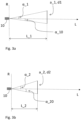
- Figs. 3a-b depict respective plane views, or respective planes, which are rotated relative each other with respect to a common rotation axis R.
- the respective planes are defined by the rotation axis R, i.e. the rotation axis R extends in each plane.
- the rotation axis R is associated with the image obtaining device 10 and is perpendicular to a plane defined by the first line A and the second longitudinal line X as shown in fig. 1 .
- Each respective plane intersects one of the first and second vehicle portions a_1, a_2.
- the rotation axis R may be a vertical line, as seen when the vehicle 100 and the second vehicle 120 are provided on a flat horizontally extending surface.
- each one of the respective planes may be vertically extending planes.
- the axis L as shown in figs. 3a-b represents a length from the image obtaining device 10 in the direction towards the vehicle 100.
- the first trigonometric model may thereby be based on a first triangle and a second triangle as shown in figs. 3a-b . Accordingly, in the shown embodiment, the first distance L_1 to the first vehicle portion a_1 with respect to the image obtaining device 10 is determined by the first length d1 and by angles ⁇ _1 and ⁇ _10 of the first triangle. In a similar manner, the second distance L_2 to the second vehicle portion a_2 with respect to the image obtaining device 10 is determined by the second length d2 and by angles ⁇ _2 and ⁇ _20.
- the equations for the second distance L_2 may be similar to the above equations, but with the values ⁇ _2, ⁇ _20 and d2 used instead.
- angles ⁇ _1, ⁇ _10, ⁇ _2 and ⁇ _20 are here altitude angles which may be determined from the obtained image.
- the image may be a pixel image wherein each pixel is associated with a specific azimuth and/or altitude angle with respect to a reference, in this case the line L, wherein determining the first and second distances L_1, L_2 to the first and second vehicle portions a_1, a_2 with respect to the image obtaining device 10 comprises:
- the first distance L_1 may be determined by providing the first length d1 and the first distance L_1 as sides in the first triangle with the altitude angles ⁇ _1, ⁇ _10.
- the second distance d2 may thus be determined in a similar manner, i.e. in the second triangle, but with the difference that it is instead based on the second vehicle portion a_2 and its length d2 and on the azimuth and/or altitude angles ⁇ _2 and ⁇ _20 associated with the second vehicle portion a_2.
- the method further comprises: S4: by use of the first and second distances L_1, L_2, the image and a second trigonometric model, estimating the relative angle ⁇ between the image obtaining device 10 and the vehicle 100.
- the second trigonometric model may thereby be a model in which the first and second distances L_1, L_2 are provided in a common plane which is perpendicular to the aforementioned rotation axis R.
- the respective planes for the first and second triangles may be vertically extending planes, whereby the common plane may be a horizontally extending plane.
- the respective planes for the first and second triangles may be horizontally extending planes, whereby the common plane may be a vertically extending plane.
- the method may further comprise:
- the azimuth angle ⁇ _1 may be an angle between the line L_2 and a line y1 at the front end of the vehicle 100 extending in the transverse direction y.
- the azimuth angles ⁇ _2 and ⁇ _3 may be angles between the line L_2 and a longitudinal line X1 extending in the longitudinal extension.
- the line X1 is here a line which also intersects the second vehicle portion a_2. In this case the second vehicle portion a_2 is closer to the image obtaining device 10 than the first vehicle portion a_1.
- the angles ⁇ _2 and ⁇ _3 are provided on opposite sides of the line X1, i.e. they are together 180 degrees or Pi radians.
- the angle Az_2 may as shown be an angle between the line L_2 and the line A.
- b_1 used in the above equations relates to a horizontally extending vehicle portion, in this case an outer edge of the front end of the vehicle 100 which extends between the first and second vehicle portions a_1, a_2.
- the length, or distance, of b_1 may for example be retrieved from the obtained dimension information as disclosed herein.
- Obtaining dimension information of the vehicle 100 may comprise estimating at least one of the first and second lengths d1, d2 of the first and second vehicle portions a_1, a_2, and/or it may comprise estimating the length of the horizontally extending portion b_1.
- the estimation may be based on at least one of information from the image, manual input from an operator, input from a database, and sensor information from one or more sensors which have observed the vehicle 100 during driving of the vehicle 100.
- estimating the at least one of the first and second lengths d1, d2 may comprise assuming that the vehicle 100 is formed according to a predefined geometrical shape, preferably a shaped as a rectangular block as shown in fig. 2 .
- the first and second vehicle portions ⁇ _1, a_2 are of equal length since for example a trailer body is most often formed in this way.
- the estimation of the first and second lengths d1, d2 may be based on an assumption that the vehicle has a certain width, corresponding to the distance b_1.
- a trailer most often has a standard width, and by using this standard width, the lengths d1, d2 may be obtained from the image by making a relative comparison in the image of b_1 with any one of d1, d2. For example, it may be assumed that b_1 is about 2.5 meters.
- a system 200 which comprises an image obtaining device 10 and a processing unit 30.
- the processing unit 30 is configured to estimate a relative angle ⁇ between the image obtaining device 10 and a vehicle 100, such as a trailer, wherein the relative angle ⁇ is defined by an angular difference between a first line A related to the image obtaining device 10 and a second longitudinal line X extending in a longitudinal extension of the vehicle 100.
- the processing unit 30 is configured to:
- the processing unit 30 may be any kind of processing unit, such as a processing unit comprising hardware or hardware and software for performing a method according to any one of the embodiments of the disclosure.
- the processing unit 30 may be a one single piece processing unit or it may be formed by several sub-processing units.
- the processing unit 30 may be adapted to communicate with the image obtaining device 10 by use of wired and/or wireless communication means. It may be an on-board processing unit provided on-board e.g. the second vehicle 120 as disclosed herein and/or it may be an off-board processing unit which is adapted to receive signals from and/or communicate with the image obtaining device 10. Furthermore, the processing unit 30 may utilize a computer program and/or computer readable medium as disclosed herein.
- the image obtaining device 10 may be mounted on the second vehicle 120. Alternatively, it may also be mounted on a static object, such as on a docking station for the vehicle 100, a building or the like. Furthermore, the system 200 may be configured to perform the relative angle estimation when the vehicle 100 is in a disengaged state with respect to the second vehicle 120 or the static object.
- the second vehicle 120 is shown in a side view.
- the second vehicle 120 as shown in fig. 6 comprises the system 200 (not shown in fig. 6 ), including the image obtaining device 10, according to any one of the embodiments disclosed herein.
- the method comprises: S10: determining a trajectory T for the second vehicle 120 defining a travelling path to the vehicle 100.
- the travelling path is here a travelling path to a coupling device (not shown) of the vehicle 100.
- the coupling device may be a kingpin of a semitrailer or a coupling arm of a dolly unit or trailer.
- the trajectory T is determined by use of at least one relative angle ⁇ between the vehicle 100 and the second vehicle 120, wherein the at least one relative angle ⁇ is estimated by use of a method according to any one of embodiments of the first aspect of the disclosure.
- the method further comprises: S20: docking the vehicles 120, 100 by moving the second vehicle 120 along the trajectory T to the vehicle 100.
- the method may further comprise:
- the system 200 may be configured to also perform the method as shown in fig. 7b , i.e. a method according to the fourth aspect.
- the system 200 may further be configured to send control signals to one or more movement actuators of the second vehicle 120 for moving the second vehicle 120, and/or the system 200 may be configured to send control signals to another control unit (not shown) which is configured to control the movement of the second vehicle 120.
- Movement actuators may for example be actuators for controlling at least one of steering, propulsion and braking of the second vehicle 120.
- the method may alternatively determine a trajectory for the vehicle 100 defining a travelling path to another entity, such as to a docking station, wherein the trajectory T is determined by use of at least one relative angle ⁇ between the vehicle 100 and the other entity, wherein the at least one relative angle ⁇ is estimated by use of a method according to any one of embodiments of the first aspect of the disclosure.
- the method may further comprise:
- system 200 may be provided on the second vehicle 120, in another embodiment the system 200 may be provided on the vehicle 100 instead or on the other entity, such as on the above mentioned docking station.
Landscapes
- Engineering & Computer Science (AREA)
- Transportation (AREA)
- Mechanical Engineering (AREA)
- Chemical & Material Sciences (AREA)
- Combustion & Propulsion (AREA)
- Computer Vision & Pattern Recognition (AREA)
- Physics & Mathematics (AREA)
- General Physics & Mathematics (AREA)
- Theoretical Computer Science (AREA)
- Image Analysis (AREA)
Priority Applications (1)
| Application Number | Priority Date | Filing Date | Title |
|---|---|---|---|
| EP21205688.1A EP4174776A1 (de) | 2021-10-29 | 2021-10-29 | Verfahren zur schätzung eines relativen winkels zwischen einer bildaufnahmevorrichtung und einem fahrzeug |
Applications Claiming Priority (1)
| Application Number | Priority Date | Filing Date | Title |
|---|---|---|---|
| EP21205688.1A EP4174776A1 (de) | 2021-10-29 | 2021-10-29 | Verfahren zur schätzung eines relativen winkels zwischen einer bildaufnahmevorrichtung und einem fahrzeug |
Publications (1)
| Publication Number | Publication Date |
|---|---|
| EP4174776A1 true EP4174776A1 (de) | 2023-05-03 |
Family
ID=78414583
Family Applications (1)
| Application Number | Title | Priority Date | Filing Date |
|---|---|---|---|
| EP21205688.1A Pending EP4174776A1 (de) | 2021-10-29 | 2021-10-29 | Verfahren zur schätzung eines relativen winkels zwischen einer bildaufnahmevorrichtung und einem fahrzeug |
Country Status (1)
| Country | Link |
|---|---|
| EP (1) | EP4174776A1 (de) |
Citations (4)
| Publication number | Priority date | Publication date | Assignee | Title |
|---|---|---|---|---|
| WO2008064892A1 (de) * | 2006-11-29 | 2008-06-05 | Universität Koblenz-Landau | Verfahren zum bestimmen einer position, vorrichtung und computerprogrammprodukt |
| US20180040129A1 (en) * | 2016-08-02 | 2018-02-08 | Denso International America, Inc. | Trailer articulation calculating system and method for calculating articulation angle of trailer |
| EP3552926A1 (de) * | 2018-04-09 | 2019-10-16 | Continental Automotive GmbH | Vorrichtung zur bestimmung eines winkels eines an einem fahrzeug befestigten anhängers |
| WO2019231470A1 (en) * | 2018-06-01 | 2019-12-05 | Paccar Inc | Systems and methods for autonomously backing a vehicle to a trailer |
-
2021
- 2021-10-29 EP EP21205688.1A patent/EP4174776A1/de active Pending
Patent Citations (4)
| Publication number | Priority date | Publication date | Assignee | Title |
|---|---|---|---|---|
| WO2008064892A1 (de) * | 2006-11-29 | 2008-06-05 | Universität Koblenz-Landau | Verfahren zum bestimmen einer position, vorrichtung und computerprogrammprodukt |
| US20180040129A1 (en) * | 2016-08-02 | 2018-02-08 | Denso International America, Inc. | Trailer articulation calculating system and method for calculating articulation angle of trailer |
| EP3552926A1 (de) * | 2018-04-09 | 2019-10-16 | Continental Automotive GmbH | Vorrichtung zur bestimmung eines winkels eines an einem fahrzeug befestigten anhängers |
| WO2019231470A1 (en) * | 2018-06-01 | 2019-12-05 | Paccar Inc | Systems and methods for autonomously backing a vehicle to a trailer |
Similar Documents
| Publication | Publication Date | Title |
|---|---|---|
| JP7124117B2 (ja) | トレーラの検出および自律的なヒッチング | |
| EP3016835B1 (de) | Fahrzeugsteuerungssystem | |
| EP3016836B1 (de) | Fahrzeugsteuerungssystem | |
| US11400977B2 (en) | Vehicle guidance system | |
| EP3380392B1 (de) | Automatisches andockverfahren zur anwendung bei schwerlastkraftwagen | |
| US11945499B2 (en) | Method and apparatus for trailer angle measurement and vehicle | |
| EP3672860B1 (de) | Verfahren zum lenken eines gelenkfahrzeugs | |
| EP3925865A1 (de) | Winkel- und orientierungsmessungen für fahrzeuge mit mehreren fahrbaren abschnitten | |
| US20210380109A1 (en) | System and method for determining a hitch angle for controlling a vehicle with active rear steering | |
| US12037016B2 (en) | Control system and method for a trailer or dolly | |
| EP4174776A1 (de) | Verfahren zur schätzung eines relativen winkels zwischen einer bildaufnahmevorrichtung und einem fahrzeug | |
| US20230096655A1 (en) | Method for reversing an articulated vehicle combination | |
| EP4001058A1 (de) | System zum führen eines fahrzeugs zu einem mit dem fahrzeug zu verbindenden verbindungsfahrzeug | |
| US20230194699A1 (en) | Method and system for determining an articulation angle of a vehicle combination | |
| US11952037B2 (en) | Method and apparatus in a motor vehicle for reversing multiple trailers | |
| WO2022188961A1 (en) | A method for estimating one or more geometric properties of a vehicle, and corresponding control unit, computer program, computer readable medium and vehicle | |
| SE2051312A1 (en) | Method and control arrangement for determining displacement of a sensor in relation to a reference pose |
Legal Events
| Date | Code | Title | Description |
|---|---|---|---|
| PUAI | Public reference made under article 153(3) epc to a published international application that has entered the european phase |
Free format text: ORIGINAL CODE: 0009012 |
|
| STAA | Information on the status of an ep patent application or granted ep patent |
Free format text: STATUS: THE APPLICATION HAS BEEN PUBLISHED |
|
| AK | Designated contracting states |
Kind code of ref document: A1 Designated state(s): AL AT BE BG CH CY CZ DE DK EE ES FI FR GB GR HR HU IE IS IT LI LT LU LV MC MK MT NL NO PL PT RO RS SE SI SK SM TR |
|
| STAA | Information on the status of an ep patent application or granted ep patent |
Free format text: STATUS: REQUEST FOR EXAMINATION WAS MADE |
|
| 17P | Request for examination filed |
Effective date: 20231101 |
|
| RBV | Designated contracting states (corrected) |
Designated state(s): AL AT BE BG CH CY CZ DE DK EE ES FI FR GB GR HR HU IE IS IT LI LT LU LV MC MK MT NL NO PL PT RO RS SE SI SK SM TR |