EP3016836B1 - Fahrzeugsteuerungssystem - Google Patents
Fahrzeugsteuerungssystem Download PDFInfo
- Publication number
- EP3016836B1 EP3016836B1 EP14737197.5A EP14737197A EP3016836B1 EP 3016836 B1 EP3016836 B1 EP 3016836B1 EP 14737197 A EP14737197 A EP 14737197A EP 3016836 B1 EP3016836 B1 EP 3016836B1
- Authority
- EP
- European Patent Office
- Prior art keywords
- trailer
- target
- vehicle
- destination
- tar
- Prior art date
- Legal status (The legal status is an assumption and is not a legal conclusion. Google has not performed a legal analysis and makes no representation as to the accuracy of the status listed.)
- Active
Links
- 238000000034 method Methods 0.000 claims description 19
- 230000002401 inhibitory effect Effects 0.000 claims description 3
- 238000012545 processing Methods 0.000 description 15
- 239000002131 composite material Substances 0.000 description 12
- 238000004364 calculation method Methods 0.000 description 8
- 230000008859 change Effects 0.000 description 7
- 230000006870 function Effects 0.000 description 7
- 238000004458 analytical method Methods 0.000 description 5
- 230000008878 coupling Effects 0.000 description 5
- 238000010168 coupling process Methods 0.000 description 5
- 238000005859 coupling reaction Methods 0.000 description 5
- 238000001514 detection method Methods 0.000 description 5
- 238000004422 calculation algorithm Methods 0.000 description 4
- 230000002441 reversible effect Effects 0.000 description 4
- 230000001133 acceleration Effects 0.000 description 3
- 238000003384 imaging method Methods 0.000 description 3
- 230000003287 optical effect Effects 0.000 description 3
- 230000002829 reductive effect Effects 0.000 description 3
- 239000008709 Curare Substances 0.000 description 1
- 230000006399 behavior Effects 0.000 description 1
- 230000015572 biosynthetic process Effects 0.000 description 1
- 230000001413 cellular effect Effects 0.000 description 1
- 238000004891 communication Methods 0.000 description 1
- 238000004590 computer program Methods 0.000 description 1
- 238000012790 confirmation Methods 0.000 description 1
- 238000011217 control strategy Methods 0.000 description 1
- 238000011161 development Methods 0.000 description 1
- 244000144972 livestock Species 0.000 description 1
- 239000003550 marker Substances 0.000 description 1
- 238000012986 modification Methods 0.000 description 1
- 230000004048 modification Effects 0.000 description 1
- 238000009877 rendering Methods 0.000 description 1
- 230000003068 static effect Effects 0.000 description 1
- 238000012546 transfer Methods 0.000 description 1
- 230000000007 visual effect Effects 0.000 description 1
Images


Classifications
-
- B—PERFORMING OPERATIONS; TRANSPORTING
- B62—LAND VEHICLES FOR TRAVELLING OTHERWISE THAN ON RAILS
- B62D—MOTOR VEHICLES; TRAILERS
- B62D13/00—Steering specially adapted for trailers
- B62D13/06—Steering specially adapted for trailers for backing a normally drawn trailer
-
- B—PERFORMING OPERATIONS; TRANSPORTING
- B62—LAND VEHICLES FOR TRAVELLING OTHERWISE THAN ON RAILS
- B62D—MOTOR VEHICLES; TRAILERS
- B62D15/00—Steering not otherwise provided for
- B62D15/02—Steering position indicators ; Steering position determination; Steering aids
- B62D15/027—Parking aids, e.g. instruction means
- B62D15/0285—Parking performed automatically
-
- B—PERFORMING OPERATIONS; TRANSPORTING
- B60—VEHICLES IN GENERAL
- B60T—VEHICLE BRAKE CONTROL SYSTEMS OR PARTS THEREOF; BRAKE CONTROL SYSTEMS OR PARTS THEREOF, IN GENERAL; ARRANGEMENT OF BRAKING ELEMENTS ON VEHICLES IN GENERAL; PORTABLE DEVICES FOR PREVENTING UNWANTED MOVEMENT OF VEHICLES; VEHICLE MODIFICATIONS TO FACILITATE COOLING OF BRAKES
- B60T8/00—Arrangements for adjusting wheel-braking force to meet varying vehicular or ground-surface conditions, e.g. limiting or varying distribution of braking force
- B60T8/17—Using electrical or electronic regulation means to control braking
- B60T8/1701—Braking or traction control means specially adapted for particular types of vehicles
- B60T8/1708—Braking or traction control means specially adapted for particular types of vehicles for lorries or tractor-trailer combinations
-
- B—PERFORMING OPERATIONS; TRANSPORTING
- B60—VEHICLES IN GENERAL
- B60W—CONJOINT CONTROL OF VEHICLE SUB-UNITS OF DIFFERENT TYPE OR DIFFERENT FUNCTION; CONTROL SYSTEMS SPECIALLY ADAPTED FOR HYBRID VEHICLES; ROAD VEHICLE DRIVE CONTROL SYSTEMS FOR PURPOSES NOT RELATED TO THE CONTROL OF A PARTICULAR SUB-UNIT
- B60W30/00—Purposes of road vehicle drive control systems not related to the control of a particular sub-unit, e.g. of systems using conjoint control of vehicle sub-units
- B60W30/06—Automatic manoeuvring for parking
-
- B—PERFORMING OPERATIONS; TRANSPORTING
- B62—LAND VEHICLES FOR TRAVELLING OTHERWISE THAN ON RAILS
- B62D—MOTOR VEHICLES; TRAILERS
- B62D15/00—Steering not otherwise provided for
- B62D15/02—Steering position indicators ; Steering position determination; Steering aids
- B62D15/025—Active steering aids, e.g. helping the driver by actively influencing the steering system after environment evaluation
-
- B—PERFORMING OPERATIONS; TRANSPORTING
- B62—LAND VEHICLES FOR TRAVELLING OTHERWISE THAN ON RAILS
- B62D—MOTOR VEHICLES; TRAILERS
- B62D15/00—Steering not otherwise provided for
- B62D15/02—Steering position indicators ; Steering position determination; Steering aids
- B62D15/027—Parking aids, e.g. instruction means
- B62D15/028—Guided parking by providing commands to the driver, e.g. acoustically or optically
-
- G—PHYSICS
- G01—MEASURING; TESTING
- G01C—MEASURING DISTANCES, LEVELS OR BEARINGS; SURVEYING; NAVIGATION; GYROSCOPIC INSTRUMENTS; PHOTOGRAMMETRY OR VIDEOGRAMMETRY
- G01C21/00—Navigation; Navigational instruments not provided for in groups G01C1/00 - G01C19/00
- G01C21/26—Navigation; Navigational instruments not provided for in groups G01C1/00 - G01C19/00 specially adapted for navigation in a road network
- G01C21/34—Route searching; Route guidance
- G01C21/3407—Route searching; Route guidance specially adapted for specific applications
-
- B—PERFORMING OPERATIONS; TRANSPORTING
- B60—VEHICLES IN GENERAL
- B60T—VEHICLE BRAKE CONTROL SYSTEMS OR PARTS THEREOF; BRAKE CONTROL SYSTEMS OR PARTS THEREOF, IN GENERAL; ARRANGEMENT OF BRAKING ELEMENTS ON VEHICLES IN GENERAL; PORTABLE DEVICES FOR PREVENTING UNWANTED MOVEMENT OF VEHICLES; VEHICLE MODIFICATIONS TO FACILITATE COOLING OF BRAKES
- B60T2201/00—Particular use of vehicle brake systems; Special systems using also the brakes; Special software modules within the brake system controller
- B60T2201/10—Automatic or semi-automatic parking aid systems
-
- B—PERFORMING OPERATIONS; TRANSPORTING
- B60—VEHICLES IN GENERAL
- B60T—VEHICLE BRAKE CONTROL SYSTEMS OR PARTS THEREOF; BRAKE CONTROL SYSTEMS OR PARTS THEREOF, IN GENERAL; ARRANGEMENT OF BRAKING ELEMENTS ON VEHICLES IN GENERAL; PORTABLE DEVICES FOR PREVENTING UNWANTED MOVEMENT OF VEHICLES; VEHICLE MODIFICATIONS TO FACILITATE COOLING OF BRAKES
- B60T2230/00—Monitoring, detecting special vehicle behaviour; Counteracting thereof
- B60T2230/08—Driving in reverse
Definitions
- the present disclosure relates to a vehicle control system; a vehicle; and a method of controlling a vehicle.
- GB 2447672 It is known from GB 2447672 to provide a computing unit to calculate a hitch angle between a trailer and a vehicle.
- the computing unit uses image data from three video cameras, fitted respectively to the rear of the vehicle and one on each door mirror, to track the position of a trailer-mounted marker to determine the position of the trailer relative to the vehicle.
- the computing unit can also predict a trailer target route and this is output to the driver on a display as guide lines overlaid onto a camera view.
- DE102006035021 discloses a driver assistance device which calculates a trajectory of a towing vehicle and/or a trailer.
- a driver of the towing vehicle can determine if the calculated trajectory intersects an obstacle and/or intersects a target location.
- DE 102007032720 is considered as the closest prior art and discloses a method of simulating driver behaviour to determine an optimal vehicle trajectory or associated sequence of movements based thereon to assist a driver, the method comprising: identifying permissible target trailer destinations; receiving an input to define a user-specified target trailer destination; determining a current trailer position; modelling a target route from the current trailer position to the target trailer destination; and outputting a vehicle control signal to guide the trailer along the target route.
- the present invention relates to an improved control system.
- a system for controlling a vehicle to facilitate reversing a trailer coupled to the vehicle comprising a processor configured to:
- the vehicle control signal can define the required steering angle inputs for the vehicle to guide the trailer along the target route. These could be output, for example to an audio or visual system, to prompt the user to make appropriate changes to the steering angle. Alternatively, the vehicle control signal can be output to steering control means for controlling the steering angle.
- the steering control means can, for example, comprise electronic power assisted steering (EPAS).
- the current trailer position can define a current hitch angle (between the vehicle and the trailer) which determines an actual travel direction of the trailer.
- the current trailer position can be determined based on one or more sensor signals.
- the current trailer position can be measured by one or more sensors, such as a rotary sensor, provided at the coupling between the vehicle and the trailer for measuring a hitch angle of the trailer.
- the current trailer position could be determined by measuring the orientation of the trailer in relation to the vehicle, for example employing one or more ultrasonic sensors or one or more image sensors (for example disposed in a camera).
- the image data generated by said one or more image sensors could be analysed to track the trailer, for example by identifying a feature of the trailer and/or a target provided on the trailer.
- the target trailer destination can comprise position (i.e. spatial) data; and/or orientation (i.e. angular) data.
- the processor can determine the spatial and/or angular relationship between the current trailer position and the target trailer destination.
- the target route can comprises one or more curves; and/or one or more linear sections.
- the target route can comprise only one reversing movement; or can comprise a sequence of forward and reversing movements.
- the user could specify whether a single reversing movement or multiple reversing movements are performed.
- the processor could be configured to output braking signals and/or acceleration signals for controlling the braking and acceleration respectively of the vehicle. Alternatively, the driver of the vehicle can control one or both of vehicle acceleration and braking.
- the processor can be configured to output driver prompts, for example to perform one or more of the following functions: accelerate, decelerate, change gear (such as select Drive or Reverse), engage parking brake and so on.
- the processor could be configured to inhibit the maximum speed of the vehicle, for example to 10km/h.
- the vehicle control signal can map a centre point of the trailer to the target route.
- the vehicle control signal can be generated to maintain the centre point of the trailer substantially coincident with the target route.
- the target route can define a target trailer travel direction at each point along its length.
- the processor can be configured to control the vehicle to match the actual trailer travel direction to the target trailer travel direction as it travels along the target route.
- the vehicle control signal can control the steering angle of the vehicle to maintain the actual trailer travel direction at least substantially coincident with the target trailer travel direction.
- the actual trailer travel direction can thereby match the target trailer travel direction.
- the processor is configured to identify permissible target trailer destinations.
- the permissible target trailer destinations could be based on the identification of one or more obstructions.
- the processor can be configured to identify said permissible target trailer destinations based on one or more of the following: a maximum permissible hitch angle; the detected space available for the trailer and/or the vehicle; a detected terrain parameter (such as an incline or gradient).
- the processor is configured to inhibit selection of an impermissible target trailer destination.
- the processor can be configured to receive image data from one or more video cameras disposed on the vehicle and/or the trailer.
- the processor can comprise an image processing module for identifying obstruction(s) in video image data obtained from one or more optical cameras.
- the image processing module can be configured to identify one or more obstructions proximal to the trailer and/or the vehicle.
- ultrasonic and/or laser sensor systems could be provided for detecting said obstruction(s).
- the processor could be configured dynamically to modify the target route if an obstruction is identified.
- the processor could be configured to determine if there is sufficient space available to manoeuvre the trailer to the target trailer destination. Based on predefined trailer parameters (such as the trailer length, width and axle location), the processor can calculate a route corridor required to reverse the trailer. The imaging system can then identify obstacles proximal to the vehicle and/or the trailer and determine if there is sufficient space available to reverse the trailer. The processor can be configured to modify the target route of the trailer to remain within the calculated route corridor.
- trailer parameters such as the trailer length, width and axle location
- the processor can be configured to output the target trailer destination and/or the target route to a display.
- the target trailer destination and/or the target route could, for example, be overlaid onto a video image from one or more of said video camera(s).
- the target trailer destination is specified by a user.
- a human machine interface can be provided for specifying the target trailer destination.
- the human machine interface can, for example, comprise a display device, such as an LCD screen.
- An input means can be provided for the human machine interface.
- the input means can, for example, comprise one or more of the following: a touchscreen, a capacitive sensor, a joystick, a rotary wheel, a trackball, voice recognition, gesture recognition, and eye tracking.
- a graphical image can be displayed on the display device to represent the target trailer destination. The position and/or the orientation of the graphical image can be controlled using the input means. The position and/or the orientation of the graphical image can be converted to data to identify said target trailer destination and output to the processor.
- a scaling function can be applied to the graphical image as it is moved around the screen.
- the scaling function has particular application when the graphical image is displayed in a perspective view, for example as an overlay onto a video image from a camera disposed on the vehicle or the trailer.
- the graphical image can represent a footprint of the trailer, for example representing an outline of the trailer on the ground.
- the graphical image could, for example, comprise a rectangle.
- the graphical image could provide a 3-dimensional representation of the trailer, for example a vector image or a rendering of the trailer.
- the graphical image can provide a scale representation of the trailer.
- the vehicle control signal can comprise a steering control signal for controlling a steering angle of the vehicle.
- a vehicle comprising a vehicle control system of the type described herein.
- a method of controlling a vehicle to facilitate reversing a trailer to a specified target trailer destination comprising:
- the method may comprise identifying permissible target trailer destinations based on one or more of the following: a maximum permissible hitch angle; the detected space available for the trailer and/or the vehicle; and a detected terrain parameter.
- the method comprises inhibiting selection of an impermissible target trailer destination.
- a computer program product comprising a computer readable storage medium including computer readable program code, where the computer readable program code when executed on a computer causes the computer to perform the method(s) described herein.
- processors used herein are to be understood as covering both single processors and multiple processors.
- a vehicle control system 1 for assisting with the reversing of a vehicle 3 and a trailer 5 in accordance with an aspect of the present invention will now be described with reference to Figures 1 to 9 .
- the vehicle control system is operable to facilitate reversing of the trailer 5 when it is coupled to the vehicle 3 (the combination of the vehicle 3 and the trailer 5 can be referred to as 'a rig'). More specifically, the vehicle control system 1 is configured to control the steering of the vehicle 3 such that the trailer 5 is reversed to a target trailer destination D TAR specified by the user. In the present embodiment, the operation of the throttle and brakes of the vehicle 3 are controlled by the user, but these control functions could be automated.
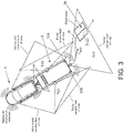
- FIG. 1 A plan view of the vehicle 3 and the trailer 5 is shown in Figure 1 .
- the vehicle 3 has two front wheels W1, W2 and two rear wheels W3, 4.
- the front wheels W1, W2 of the vehicle 3 are steerable in conventional manner to define a steering angle ⁇ .
- the trailer 5 has two wheels TW1, TW2 which are not steerable.
- the vehicle 3 is provided with a vehicle imaging system comprising a centrally mounted rear vehicle camera 9; and left and right side vehicle cameras 10, 11 mounted in respective wing mirrors 13, 15.
- the vehicle cameras 9, 10, 11 are optical cameras arranged to face to the rear of the vehicle 3 and their fields of view V1, V2, V3 are illustrated by dashed triangles.
- the vehicle 3 optionally also comprises an obstruction detection system, for example side radar systems 7A, 7B for detecting the presence of an obstruction in the rear three quarters position of the vehicle 3.
- an obstruction detection system for example side radar systems 7A, 7B for detecting the presence of an obstruction in the rear three quarters position of the vehicle 3.
- a tow hitch 17 is mounted to the vehicle 3 for coupling to a trailer coupling 19 mounted to the trailer 5.
- the tow hitch 17 is an upwardly projecting tow ball in the present embodiment.
- the trailer coupling 19 is mounted to a hitch frame 21 disposed at the front of the trailer 5.
- the hitch frame 21 is an A-frame having a front apex 23 to which the trailer coupling 19 is mounted.
- a target 25 is mounted to a front face 27 of the trailer 5 to enable the position of the trailer 5 relative to the vehicle 3 to be determined, as described herein.
- the target 25 is a visible image comprising three circles arranged in a triangular formation. It will be appreciated that the present invention can be implemented with other targets 25, for example comprising different symbols/images or non-visible targets.
- the trailer 5 is provided with a trailer imaging system comprising a centrally mounted rear trailer camera 29; and left and right side trailer cameras 30, 31 mounted on respective sides of the trailer 5.
- the trailer cameras 29, 30, 31 are optical cameras arranged to provide video images of the area around the trailer 5 which may otherwise be obscured from view.
- the fields of view TV1, TV2, TV3 of the trailer cameras 29, 30, 31 are illustrated by dashed triangles in Figures 3 and 4 .
- the trailer 5 optionally also comprises an obstruction detection system, for example parking sensors 32A, 32B, for detecting the presence of obstructions at the rear of the trailer 5.
- the image data from the trailer cameras 29, 30, 31 and/or obstruction data from the obstruction detection system is transmitted to the vehicle 3 over either a wired connection or a wireless communication channel.
- the vehicle control system 1 comprises an electronic control unit (ECU) having an electronic processor 33, as shown schematically in Figure 2 .
- the processor 33 comprises image processing means in the form of an image processing module 33A for analysing the image data.
- the vehicle cameras 9, 10, 11 and the trailer cameras 29, 30, 31 each output image data to the image processing module 33A for analysis.
- the image processing module 33A analyses the image data from the vehicle cameras 9, 10, 11 to identify the target 25 to determine the current position of the trailer 5 in relation to the vehicle 3.
- the image processing module determines the current orientation of the trailer 5 relative to the vehicle 3.
- the image processing module 33A analyses the image data from the trailer cameras 29, 30, 31 to identify obstructions proximal to the trailer 5.
- the image processing module 33A can optionally analyse the image data from the vehicle cameras 9, 10, 11 to identify obstructions proximal to the vehicle 3 and trailer 5.
- the image processing module 33A is configured to multiplex the images from the trailer cameras 29, 30, 31 to generate a composite image 35 showing a panoramic view to the rear of the trailer 5, as shown in Figure 9 .
- the resulting composite image 35 can be output to a display screen 37 to be viewed by the user substantially in real-time.
- the display screen 37 can be provided in an instrument cluster or in an infotainment console.
- the image data from the vehicle cameras 9, 10, 11 and the trailer cameras 29, 30, 31 could be combined to provide a plan view of the vehicle 3 and the trailer 5 (as if viewed from a position above the vehicle 3 and the trailer 5).
- the processor 33 further comprises vehicle/trailer guidance means in the form of a guidance module 33B.
- the guidance module 33B is provided to assist with guiding the trailer 5 when the vehicle 3 and the trailer 5 are being reversed together.
- the guidance module 33B is configured to output a control signal for controlling the steering angle ⁇ of the front wheels W1, W2 of the vehicle 3 to guide the trailer 5 along a target route R.
- the target route R is generated by the guidance module 33B to guide the trailer 5 from its current position to a target destination D TAR specified by the user.
- the target route R is illustrated by a dashed line in Figure 3 and the path to be followed by the wheels W1, W2 of the trailer 3 are represented by arcuate lines in Figure 4 .
- the vehicle control system 1 comprises a human machine interface (HMI) module 39.
- the HMI module 39 is coupled to the display screen 37 and is configured to superimpose a graphical image 41, representing the target destination D TAR of the trailer 5, onto the composite image 35.
- the graphical image 41 comprises a rectangle 43 which represents the footprint of the trailer 5.
- the graphical image 41 is sized to provide a scale representation of the trailer 5 within the composite image 35.
- the trailer dimensions can be specified by the user and stored in a data file accessible to the HMI module 39.
- a portion of the graphical image 41 is semi-transparent to reduce obfuscation of objects in the composite image 35. It will be appreciated that the present invention is not limited to the display of a rectangle 43 and other graphical images 39 can be used to represent the trailer 5.
- the HMI module 39 is coupled to input means 45 in the form of a touch screen and a rotary dial.
- the input means 45 can be operated by the user to position the graphical image 41 within the composite image 35. The user can thereby position the graphical image 41 to specify the target destination D TAR for the trailer 5, typically corresponding to a location where the trailer 5 is to be parked.
- the input means 45 can optionally also enable the user to define the orientation of the trailer 5 in relation to the vehicle 3, for example by adjusting the angular orientation of the rectangle 43.
- the HMI module 39 performs a scaling operation on the graphical image 41 to adjust its size based on its position within the composite image 35, for example to increase/decrease its size in dependence on its virtual position in relation to the camera generating the video image.
- the graphical image 41 can optionally also be modified to alter its perspective, for example to simulate foreshortening, as it is moved within the composite image 35.
- the graphical image 41 can thereby provide an accurate representation of the size of the trailer 5 within the composite image 35.
- the processor 33 could be configured to identify areas or regions which are unsuitable for positioning the trailer 5.
- the HMI module 39 can be configured to represent any such areas as an overlay on the composite image 35.
- the HMI module 39 can be configured to prevent the graphical image 41 being moved to locations identified by the processor 33 as being unsuitable for positioning the trailer 5.
- the processor 33 could determine that a region displayed in the composite image 35 is unsuitable due to the detection of one or more obstructions by the image processing module 33A.
- the processor 33 could assess one or more terrain parameters, such as incline or gradient, to identify unsuitable regions for the trailer 5.
- the terrain parameters could be assessed from the image data derived from the vehicle cameras 9, 10, 11 and/or the trailer cameras 29, 30, 31.
- one or more of the following types of sensor could be employed to monitor the terrain: ultrasonic sensors/cameras, laser scanners and radar.
- the resulting terrain data could be used to restrict selection of the target destination D TAR ; and/or control vehicle operating parameters, for example to engage four wheel drive or to select a low transfer range; and/or request user confirmation of the selected target destination D TAR .
- the guidance module 33B is configured to generate the target route R to guide the trailer 5 from its current location to the target destination D TAR specified by the user.
- the target route R defines a target trailer travel direction T TAR for guiding the trailer 5 from its current position to the target destination D TAR .
- the target route R can comprise rectilinear and/or curved sections.
- the target route R is arranged coincident with a midpoint of the trailer 5 in its current position.
- the current position of the trailer 5 is monitored compared to the originally calculated target route R. Small deviations are managed within the vehicle control system 1. Larger deviations can trigger a recalculation of the target route R. If the target destination D TAR becomes unachievable from the current position, the user is alerted and a corrective manoeuvre is suggested (for example travel forward a short distance).
- the user positions the graphical image 41 within the composite image 35 to define the target destination D TAR of the trailer 5.
- the guidance module 33B determines the target route R between the current trailer position and the specified target destination D TAR .
- the vehicle steering angle ⁇ is controlled such that a centre of rotation 49 of the trailer 5 defines a first path 51 which at least substantially matches the target route R.
- the trailer hitch 19 defines a second path 53 as the trailer 5 follows the target route R; and a centre of rotation 55 of the vehicle 3 defines a third path 57 as the trailer 5 follows the target route R.
- the guidance module 33B could be configured to generate the second or third paths 53, 55 to guide the trailer 5 to the target destination D TAR and to control the vehicle steering angle ⁇ to follow said second or third paths 53, 55.
- the target route R is a straight line if the target destination D TAR is in line with the trailer 5.. Otherwise, the target route R comprises a curve based on the geometry of the vehicle and trailer and location of the target destination.
- the guidance module 33B implements a geometric algorithm to generate the target route R.
- the guidance module 33B utilises the angular offset between the current trailer longitudinal axis X2 and the target trailer longitudinal axis X2 TAR ; and the lateral offset between the current trailer position and the target destination D TAR (measured perpendicular to the trailer longitudinal axis X2.
- the algorithm defines a default S-shaped path 55 (shown in phantom in Figures 6B-6E ) comprising first and second curves A, B.
- the first curve A defines a first included angle of +45°; and the second curve B defines a second included angle of -45°.
- a scaling function (along an X axis and/or a Y axis) is applied to the S-shaped path 55 to link the actual longitudinal axis X2 of the trailer 5 to the target longitudinal axis X2 TAR of the trailer 5 when it is in the target destination D TAR .
- the guidance module 33B can optionally be configured to define a minimum radius of curvature for the first and second curves A, B to ensure that the hitch angle ⁇ does not equal or exceed the jack-knife angle.
- the S-shaped path 55 is positioned to link the actual longitudinal axis X2 of the trailer 5 to the target longitudinal axis X2 TAR .
- a scaling function and/or a rotation function can be applied to the S-shaped path 55 depending on the position and/or orientation of the target destination D TAR in relation to the current trailer position.
- the S-shaped path 55 is then modified by adjusting the included angle of either the first curve A or the second curve B in dependence on the angular offset between the actual longitudinal axis X2 and the target longitudinal axis X2 TAR .
- the guidance module 33B identifies which of the first and second curves A, B opens onto the side of the S-shaped path 55 to which the target longitudinal axis X2 TAR is oriented.
- the guidance module 33B modifies the included angle of the identified curve A, B corresponding to the angular offset between the actual longitudinal axis X2 and the target longitudinal axis X2 TAR . This technique will now be described with reference to Figures 6B-6E .
- the target longitudinal axis X2 TAR is offset by -45° and is directed to the left side of the S-shaped path 55. Accordingly, the included angle of the first curve A (which opens to the left side of the S-shaped path 55) is reduced by 45°. As the pre-defined included angle is +45°, the first curve A is effectively removed from the S-shaped path 55 leaving only the second curve B. The resulting modified curve is defined as the target route R.
- the target longitudinal axis X2 TAR is offset by -90° and is directed to the left side of the S-shaped path 55. Accordingly, the included angle of the first curve A is reduced by 90° to define an included angle of -45°, thereby reversing the curvature direction of the first curve A.
- the resulting modified curve is defined as the target route R.
- the target longitudinal axis X2 TAR is offset by +45° and is directed to the right side of the S-shaped path 55. Accordingly, the included angle of the second curve B (which opens to the right side of the S-shaped path 55) is increased by 45°. As the pre-defined included angle is -45°, the second curve B is effectively removed from the S-shaped path 55 leaving only the first curve A. The resulting modified curve is defined as the target route R.
- the target longitudinal axis X2 TAR is offset by +90° and is directed to the right side of the S-shaped path 55. Accordingly, the included angle of the second curve B is increased. However, to compensate for the lateral offset of the trailer 5, the second curve B is increased by 45° to 0°, thereby removing the second curve B. The first curve A is also increased by 45° to 90° (again to compensate for the lateral offset of the target destination D TAR ). The resulting modified curve is defined as the target route R.
- the vehicle control system 1 attempts to identify the presence of any obstructions (denoted generally by the reference numeral 46 in Figures 7A and 7B ).
- Typical obstructions include kerbs, walls, vehicles, etc.
- the vehicle control system 1 can optionally also determine terrain parameters, for example to detect a metalled surface indicating a road; and/or terrain features, for example gradient changes.
- the obstructions 46 can be identified by the image processing module 33A and/or other detection systems.
- the guidance module 33B modifies the target route R generated in the first process step. By way of example, the guidance module 33B will give a higher priority to a route which guides the trailer 5 to the target destination D TAR whilst remaining on a road than a route which provides the shortest achievable path.
- the guidance module 33B calculates the required vehicle steering angle ⁇ to achieve the appropriate trailer angle ⁇ at intervals x, 2x, 3x... nx along the route R, where x equals half the combined length of the vehicle 3 and the trailer 5.
- the interval distance x is configurable and can be reduced, for example to 1 ⁇ 4 the combined length of the vehicle 3 and the trailer 5 to provide improved accuracy, albeit at the expense of increased processing load on the processor 33
- the trailer angle ⁇ is the angle between an expected angular position of the trailer 5 at a particular interval and the position of the trailer 5 before the manoeuvre starts.
- the trailer angles ⁇ n , ⁇ n+1 at adjacent calculation points are compared to determine the difference between the trailer hitch angles ⁇ n , ⁇ n+1 at adjacent interval points.
- the guidance module 33B stores the values in memory and, during the manoeuvre, accesses the stored values after each interval to set the next interval value as the desired hitch angle ⁇ . If the guidance module 33B detects a large deviation between the present hitch angle ⁇ and the expected hitch angle ⁇ it restarts the calculation to avoid failure.
- the guidance module 33B compares the required hitch angle ⁇ n , ⁇ n+1 between first and second intervals x to establish if this hitch angle ⁇ can be achieved while considering surrounding conditions. If the comparison of the hitch angle ⁇ n , ⁇ n+1 between the first and second intervals x is possible, the guidance module 33B stores the values in memory and, during the manoeuvre, accesses the stored values after each interval to set the next interval value as the desired hitch angle ⁇ . If the guidance module 33B fails to achieve the required hitch angle ⁇ for four (4) consecutive interval points (i.e.
- an alternative target route R is calculated while considering space requirement and the surrounding obstructions 46. If the guidance module 33B is unable to establish a viable alternative target route R, the guidance module 33B calculates an alternate position between failure points identified by means of driving forward in the available space to complete the manoeuvre. During the route calculation the guidance module 33B determines whether the hitch angle ⁇ change between two intervals can be achieved. If the hitch angle ⁇ cannot be achieved then the calculation needs to check if the hitch angle ⁇ change calculated in alternative routes in two previous and two subsequent intervals can be achieved. If this fails then the calculation starts again or requests an initial drive forwards to reduce the rate of change of hitch angle. A forward shuffle could also be requested mid-manoeuvre.
- the angular change ⁇ in the trailer angle ⁇ at intervals along the target route R is illustrated in Figure 7B .
- the angular change ⁇ is illustrated with reference to a first time t and a second time t+1, but the calculation of the required angle change is based on distance rather than time.
- the steering angle ⁇ of the vehicle 3 is controlled to maintain the actual travel direction T ACT of the trailer 5 substantially coincident with the target trailer travel direction T TAR during the reversing manoeuvre along said target route R.
- the guidance module 33B can control the steering angle ⁇ of the front wheels W1, W2 to guide the trailer 5 along the target travel direction T TAR .
- the control algorithm for generating a control signal to guide the vehicle 3 along the target route R will now be described with reference to Figure 9 .
- the vehicle 3 has a first longitudinal axis X1 and the trailer 5 has a second longitudinal axis X2.
- the angular offset between the first and second longitudinal axes X1, X2 is referred to as the hitch angle ⁇ .
- the trailer 5 travels in a direction T ACT corresponding to the hitch angle ⁇ (unless the hitch angle ⁇ exceeds a jack-knife angle for the trailer 5, as described herein).
- the image processing module 33A calculates the hitch angle ⁇ with reference to the target 25 and outputs a hitch angle signal to the guidance module 33B.
- ⁇ t+1 and ⁇ t are the steering angles of the vehicle 3 at frame t+1 and t (auto steering command from the algorithm and current steering from the CAN respectively); ⁇ req and ⁇ cur are the requested and current hitch angles; ⁇ is the maximum steering offset value; and k is a constant multiplier.
- the value of the gain k can be calculated based on the relationship between ⁇ and ⁇ , as shown in Figure 8 .
- the relationship between ⁇ and ⁇ is one (1) for small angles and so the gain k can be set to a value of one (1).
- the gain k thereby compensates for the fact that longer trailers take longer to reach the requested hitch angle ⁇ .
- the guidance module 33B is configured to calculate a maximum permissible hitch angle ⁇ MAX . If the hitch angle ⁇ exceeds the maximum permissible hitch angle ⁇ MAX (which in the present embodiment is the jack-knife angle of the trailer 5), it is no longer possible to reduce the hitch angle ⁇ by continuing to reverse (i.e. the trailer 5 has jack-knifed). If the detected hitch angle ⁇ is equal to or exceeds the calculated jack-knife angle, the vehicle control system 1 will advise the user to drive forward until it determines that the trailer angle ⁇ at the next interval is achievable while considering space and obstructions.
- R is the turning radius
- ⁇ is the steering angle of the vehicle 3
- d is the wheelbase of the vehicle 3
- h is the tow bar offset of the vehicle 3
- L is the hitch length of the trailer 5;
- the wheelbase d, the tow bar offset h and the maximum steering angle ⁇ MAX of the vehicle 3 are defined for the vehicle 3.
- the hitch length L of the trailer 5 is entered during trailer setup by the user (or can be determined during a calibration exercise).
- the guidance module 33B outputs a maximum hitch angle signal to indicate the maximum permissible hitch angle ⁇ MAX for the current steering angle ⁇ .
- the guidance module 33B is configured to inhibit the trailer travel direction T ACT to values which are less than the maximum permissible hitch angle ⁇ MAX .
- a minimum radius of curvature of the target route R can be defined to ensure that the trailer travel direction T ACT is less than or equal to the maximum permissible hitch angle ⁇ MAX .
- the guidance module 33B calculates the initial required steering angle ⁇ to achieve the desired hitch angle ⁇ , then iteratively calculates the required steering angle ⁇ and hitch angle ⁇ .
- the guidance module 33B is configured to output a steering control signal operative to control the steering angle ⁇ of the front wheels W1, W2 to adjust the hitch angle ⁇ , thereby modifying the actual trailer travel direction T ACT .
- the guidance module 33B adjusts the steering angle ⁇ (which can be positive or negative in relation to a reference point) to increase or decrease the hitch angle ⁇ .
- the actual trailer travel direction T ACT can thereby be matched to the target trailer travel direction T TAR required to follow the target route R.
- the hitch angle signal is updated at least substantially in real time and the guidance module 33B makes corresponding real time adjustments to the steering control signal.
- the guidance module 33B controls the hitch angle ⁇ so that the difference between the actual trailer travel direction T ACT and the target trailer travel direction T TAR is at least substantially zero.
- a tolerance of +/- 0.5° between the actual trailer travel direction T ACT and the target trailer travel direction T TAR provides a good result.
- the steering angle control signal is output to an electronic power assisted steering (EPAS) module 45 to control the angle of a steering wheel 47 to provide a required steering angle ⁇ for the front wheels W1, W2.
- the EPAS module 45 automatically adjusts the angular orientation of the steering wheel 47 to provide the appropriate steering angle ⁇ at the front wheels W1, W2 to control the vehicle 3 to match the actual trailer travel direction T ACT with the target trailer travel direction T TAR .
- the user operates the HMI module 39 to position the graphical image 41 at the target destination D TAR for the trailer 5, as illustrated in Figure 9 .
- the user operates the input means 45 to guide the graphical image 41 to the desired location on the video image 35.
- the input means 45 can be operated to adjust the position and/or orientation of the target destination D TAR for the trailer 5.
- the user then confirms the target destination D TAR for the trailer 5.
- the image processing module 33A analyses the image data from the vehicle cameras 9, 10, 11 to identify the target 25 on the trailer 5 and to determine the current position of the trailer 5 in relation to the vehicle 3.
- the guidance module 33B then models a target route R for the trailer 5 from its current position to the target trailer destination D TAR .
- a vehicle control signal is output by the guidance module 33B to the EPAS module 45 to adjust the steering angle ⁇ to control the vehicle 3 to match the actual travel direction T ACT of the trailer 5 with the target travel direction T TAR .
- the HMI module 39 can optionally output instructions to prompt the user to select the appropriate drive gear and to operate the vehicle brakes and throttle.
- the EPAS module 45 in dependence on the vehicle control signal output from the guidance module 33B, then steers the vehicle 3 to guide the trailer 5 along the target route R.
- a notification can be output by the HMI module 39 to notify the user when the trailer 5 is in the target destination D TAR .
- the vehicle control system 1 can thereby facilitate reversing the trailer 5 to the target destination D TAR .
- the present invention is applicable to a range of different types of trailer 5.
- the trailer 5 can be a caravan, a goods trailer, a flatbed trailer, a van trailer, a livestock trailer and so on.
- the present invention is applicable to a range of different types of vehicles 3.
- the vehicle 3 can be a motor vehicle, such as an off-road or sports utility vehicle; or a towing engine or tractor for a semi-trailer truck.
- control techniques described herein are a development of those described in the Applicant's earlier UK patent applications GB1307524.7 (filed on 26th April 2013 ) and GB1307525.4 (filed on 26th April 2013 ).
- the vehicle control system 1 described herein without departing from the present invention.
- the graphical image 41 could be positioned on a static image such as a grid or mesh representing a predefined region around the vehicle 3.
- vehicle control system 1 has been described with reference to a set of vehicle cameras 9, 10, 11 and a set of trailer cameras 29, 30, 31, it will be appreciated that a single camera could be provided on the vehicle 3 and/or the trailer 5.
- trailer cameras 29, 30, 31 could be omitted.
- a set of parking sensors provided on the trailer 5 could, for example, provide notification to the driver of any obstructions.
- the hitch angle ⁇ could be measured directly, for example by a rotary encoder.
- a video image could be transmitted to the vehicle 3 from a remote camera (for example provided in a cellular telephone) over a wireless network such as Bluetooth®.
Landscapes
- Engineering & Computer Science (AREA)
- Transportation (AREA)
- Mechanical Engineering (AREA)
- Chemical & Material Sciences (AREA)
- Combustion & Propulsion (AREA)
- Radar, Positioning & Navigation (AREA)
- Remote Sensing (AREA)
- Automation & Control Theory (AREA)
- Physics & Mathematics (AREA)
- General Physics & Mathematics (AREA)
- Traffic Control Systems (AREA)
- Steering Control In Accordance With Driving Conditions (AREA)
- Control Of Position, Course, Altitude, Or Attitude Of Moving Bodies (AREA)
Claims (12)
- System (1) zum Steuern eines Fahrzeugs (3), um das Zurücksetzen eines an das Fahrzeug gekoppelten Anhängers (5) zu erleichtern, wobei das System einen Prozessor (33) umfasst, der zu Folgendem konfiguriert ist:Erhalten eines durch einen Benutzer festgelegten Anhängerzielorts (DTAR);Bestimmen einer aktuellen Anhängerposition;Modellieren einer Zielroute (R) von der aktuellen Anhängerposition zu dem Anhängerzielort (DTAR); undAusgeben eines Fahrzeugsteuersignals zum Steuern des Fahrzeugs (3), um den Anhänger (5) entlang der Zielroute (R) zu führen;wobei der Prozessor (33) konfiguriert ist, um zulässige Anhängerzielorte und unzulässige Anhängerzielorte zu identifizieren;wobei der Prozessor konfiguriert ist, um eine Benutzerauswahl eines unzulässigen Anhängerzielorts zu verhindern.
- System nach Anspruch 1, wobei der Anhängerzielort (DTAR) Standortdaten und/oder Ausrichtungsdaten umfasst.
- System nach Anspruch 1 oder 2, wobei die Zielroute (R) eine oder mehrere Kurven umfasst, die die aktuelle Anhängerposition mit dem Anhängerzielort verbinden (DTAR).
- System nach Anspruch 3, wobei das Fahrzeugsteuersignal einen Mittelpunkt des Anhängers (5) der Zielroute (R) zuordnet.
- System nach einem der vorhergehenden Ansprüche, wobei der Prozessor (33) konfiguriert ist, um die zulässigen Anhängerzielorte auf Grundlage eines maximal zulässigen Anhängerkupplungswinkels zu identifizieren;
und/oder eines erkannten verfügbaren Raums für den Anhänger (5);
und/oder eines erkannten Geländeparameters. - System nach einem der vorhergehenden Ansprüche, wobei der Prozessor (33) konfiguriert ist, um Bilddaten von einer oder von mehreren auf dem Fahrzeug (3) und/oder dem Anhänger (5) angeordneten Videokameras zu erhalten, optional wobei der Prozessor (33) konfiguriert ist, um eines oder mehrere Hindernisse (46) nahe dem Anhänger (5) und/oder dem Fahrzeug (3) zu identifizieren.
- System nach Anspruch 6, wobei der Prozessor (33) konfiguriert ist, um den Anhängerzielort (DTAR) und/oder eine Zielroute (R) für den Anhänger (5) über ein Videobild von einer oder von mehreren der Videokameras zu überlagern.
- System nach einem der vorhergehenden Ansprüche, wobei das Fahrzeugsteuersignal ein Lenkungssteuersignal zum Steuern eines Lenkungswinkels des Fahrzeugs (3) umfasst.
- System nach einem der vorhergehenden Ansprüche, wobei der Prozessor konfiguriert ist, um zu bestimmen, ob ausreichend Raum zum Manövrieren des Anhängers zu dem Anhängerzielort verfügbar ist.
- Fahrzeug (3), umfassend ein System (1) nach einem der vorhergehenden Ansprüche.
- Verfahren zum Steuern eines Fahrzeugs (3), um das Zurücksetzen eines Anhängers (5) zu einem festgelegten Anhängerzielort (DTAR) zu erleichtern, wobei das Verfahren Folgendes umfasst:Identifizieren von zulässigen Anhängerzielorten und unzulässigen Anhängerzielorten;Erhalten einer Eingabe, um einen benutzerdefinierten Anhängerzielort (DTAR) zu definieren;Bestimmen einer aktuellen Anhängerposition;Modellieren einer Zielroute (R) von der aktuellen Anhängerposition zu dem Anhängerzielort (DTAR); undAusgeben eines Fahrzeugsteuersignals zum Steuern des Fahrzeugs (3), um den Anhänger (5) entlang der Zielroute (R) zu führen;wobei das Verfahren das Verhindern einer Benutzerauswahl eines unzulässigen Anhängerzielorts umfasst.
- Verfahren nach Anspruch 11, wobei die zulässigen Anhängerzielorte auf Grundlage eines oder mehrerer der Folgenden identifiziert werden:eines maximal zulässigen Anhängerkupplungswinkels;des erkannten verfügbaren Raums für den Anhänger und/oder das Fahrzeug;und eines erkannten Geländeparameters.
Applications Claiming Priority (2)
| Application Number | Priority Date | Filing Date | Title |
|---|---|---|---|
| GB1312040.7A GB2520474B (en) | 2013-07-04 | 2013-07-04 | Vehicle Control System |
| PCT/EP2014/064270 WO2015001066A2 (en) | 2013-07-04 | 2014-07-03 | Vehicle control system |
Publications (2)
| Publication Number | Publication Date |
|---|---|
| EP3016836A2 EP3016836A2 (de) | 2016-05-11 |
| EP3016836B1 true EP3016836B1 (de) | 2019-02-27 |
Family
ID=49033348
Family Applications (1)
| Application Number | Title | Priority Date | Filing Date |
|---|---|---|---|
| EP14737197.5A Active EP3016836B1 (de) | 2013-07-04 | 2014-07-03 | Fahrzeugsteuerungssystem |
Country Status (4)
| Country | Link |
|---|---|
| US (1) | US9902425B2 (de) |
| EP (1) | EP3016836B1 (de) |
| GB (2) | GB2552282B (de) |
| WO (1) | WO2015001066A2 (de) |
Families Citing this family (116)
| Publication number | Priority date | Publication date | Assignee | Title |
|---|---|---|---|---|
| GB2447672B (en) | 2007-03-21 | 2011-12-14 | Ford Global Tech Llc | Vehicle manoeuvring aids |
| US9513103B2 (en) | 2011-04-19 | 2016-12-06 | Ford Global Technologies, Llc | Hitch angle sensor assembly |
| US9723274B2 (en) | 2011-04-19 | 2017-08-01 | Ford Global Technologies, Llc | System and method for adjusting an image capture setting |
| US20150197281A1 (en) * | 2011-04-19 | 2015-07-16 | Ford Global Technologies, Llc | Trailer backup assist system with lane marker detection |
| US9500497B2 (en) * | 2011-04-19 | 2016-11-22 | Ford Global Technologies, Llc | System and method of inputting an intended backing path |
| US9506774B2 (en) * | 2011-04-19 | 2016-11-29 | Ford Global Technologies, Llc | Method of inputting a path for a vehicle and trailer |
| US9969428B2 (en) | 2011-04-19 | 2018-05-15 | Ford Global Technologies, Llc | Trailer backup assist system with waypoint selection |
| US9926008B2 (en) * | 2011-04-19 | 2018-03-27 | Ford Global Technologies, Llc | Trailer backup assist system with waypoint selection |
| US9783230B2 (en) * | 2011-04-19 | 2017-10-10 | Ford Global Technologies, Llc | Trailer backup assist system with off-shoot correction |
| US9493187B2 (en) * | 2011-04-19 | 2016-11-15 | Ford Global Technologies, Llc | Control for trailer backup assist system |
| US10196088B2 (en) * | 2011-04-19 | 2019-02-05 | Ford Global Technologies, Llc | Target monitoring system and method |
| US9708000B2 (en) * | 2011-04-19 | 2017-07-18 | Ford Global Technologies, Llc | Trajectory planner for a trailer backup assist system |
| US9434414B2 (en) | 2011-04-19 | 2016-09-06 | Ford Global Technologies, Llc | System and method for determining a hitch angle offset |
| US9683848B2 (en) | 2011-04-19 | 2017-06-20 | Ford Global Technologies, Llc | System for determining hitch angle |
| US9854209B2 (en) * | 2011-04-19 | 2017-12-26 | Ford Global Technologies, Llc | Display system utilizing vehicle and trailer dynamics |
| US9555832B2 (en) | 2011-04-19 | 2017-01-31 | Ford Global Technologies, Llc | Display system utilizing vehicle and trailer dynamics |
| US9592851B2 (en) | 2013-02-04 | 2017-03-14 | Ford Global Technologies, Llc | Control modes for a trailer backup assist system |
| US9511799B2 (en) | 2013-02-04 | 2016-12-06 | Ford Global Technologies, Llc | Object avoidance for a trailer backup assist system |
| GB201312038D0 (en) | 2013-07-04 | 2013-08-21 | Jaguar Land Rover Ltd | Trailer parameter identification system |
| GB2552282B (en) * | 2013-07-04 | 2021-03-31 | Jaguar Land Rover Ltd | Vehicle control system |
| GB2515800B (en) | 2013-07-04 | 2017-06-07 | Jaguar Land Rover Ltd | Vehicle control system |
| US9464887B2 (en) | 2013-11-21 | 2016-10-11 | Ford Global Technologies, Llc | Illuminated hitch angle detection component |
| US9464886B2 (en) | 2013-11-21 | 2016-10-11 | Ford Global Technologies, Llc | Luminescent hitch angle detection component |
| DE102013020315A1 (de) * | 2013-12-05 | 2015-06-11 | Valeo Schalter Und Sensoren Gmbh | Verfahren zum Durchführen eines zumindest semi-autonomen Einparkvorgangs eines Kraftfahrzeugs, Parkassistenzsystem und Kraftfahrzeug |
| US9963004B2 (en) | 2014-07-28 | 2018-05-08 | Ford Global Technologies, Llc | Trailer sway warning system and method |
| US9517668B2 (en) | 2014-07-28 | 2016-12-13 | Ford Global Technologies, Llc | Hitch angle warning system and method |
| US10112537B2 (en) | 2014-09-03 | 2018-10-30 | Ford Global Technologies, Llc | Trailer angle detection target fade warning |
| CN106797413B (zh) * | 2014-09-30 | 2019-09-27 | 惠普发展公司,有限责任合伙企业 | 声音调节 |
| US9522677B2 (en) | 2014-12-05 | 2016-12-20 | Ford Global Technologies, Llc | Mitigation of input device failure and mode management |
| US9533683B2 (en) | 2014-12-05 | 2017-01-03 | Ford Global Technologies, Llc | Sensor failure mitigation system and mode management |
| US9607242B2 (en) | 2015-01-16 | 2017-03-28 | Ford Global Technologies, Llc | Target monitoring system with lens cleaning device |
| US9522699B2 (en) | 2015-02-05 | 2016-12-20 | Ford Global Technologies, Llc | Trailer backup assist system with adaptive steering angle limits |
| US9616923B2 (en) | 2015-03-03 | 2017-04-11 | Ford Global Technologies, Llc | Topographical integration for trailer backup assist system |
| US9804022B2 (en) | 2015-03-24 | 2017-10-31 | Ford Global Technologies, Llc | System and method for hitch angle detection |
| US9821845B2 (en) | 2015-06-11 | 2017-11-21 | Ford Global Technologies, Llc | Trailer length estimation method using trailer yaw rate signal |
| US20160375831A1 (en) * | 2015-06-23 | 2016-12-29 | GM Global Technology Operations LLC | Hitching assist with pan/zoom and virtual top-view |
| US9896126B2 (en) * | 2015-07-08 | 2018-02-20 | Ford Global Technologies, Llc | Jackknife detection for vehicle reversing a trailer |
| US9896130B2 (en) | 2015-09-11 | 2018-02-20 | Ford Global Technologies, Llc | Guidance system for a vehicle reversing a trailer along an intended backing path |
| US10144452B2 (en) * | 2015-10-08 | 2018-12-04 | Ford Global Technologies, Llc | Active adaptive haptic multi-function knob |
| US10611407B2 (en) | 2015-10-19 | 2020-04-07 | Ford Global Technologies, Llc | Speed control for motor vehicles |
| US10384607B2 (en) | 2015-10-19 | 2019-08-20 | Ford Global Technologies, Llc | Trailer backup assist system with hitch angle offset estimation |
| US9836060B2 (en) * | 2015-10-28 | 2017-12-05 | Ford Global Technologies, Llc | Trailer backup assist system with target management |
| US10017115B2 (en) | 2015-11-11 | 2018-07-10 | Ford Global Technologies, Llc | Trailer monitoring system and method |
| US9895945B2 (en) | 2015-12-08 | 2018-02-20 | Ford Global Technologies, Llc | Trailer backup assist system with hitch assist |
| US10127459B2 (en) | 2015-12-17 | 2018-11-13 | Ford Global Technologies, Llc | Trailer type identification system |
| US9610975B1 (en) | 2015-12-17 | 2017-04-04 | Ford Global Technologies, Llc | Hitch angle detection for trailer backup assist system |
| US9934572B2 (en) | 2015-12-17 | 2018-04-03 | Ford Global Technologies, Llc | Drawbar scan solution for locating trailer hitch point |
| US10155478B2 (en) | 2015-12-17 | 2018-12-18 | Ford Global Technologies, Llc | Centerline method for trailer hitch angle detection |
| US9796228B2 (en) * | 2015-12-17 | 2017-10-24 | Ford Global Technologies, Llc | Hitch angle detection for trailer backup assist system |
| US9798953B2 (en) | 2015-12-17 | 2017-10-24 | Ford Global Technologies, Llc | Template matching solution for locating trailer hitch point |
| US10011228B2 (en) | 2015-12-17 | 2018-07-03 | Ford Global Technologies, Llc | Hitch angle detection for trailer backup assist system using multiple imaging devices |
| US9827818B2 (en) | 2015-12-17 | 2017-11-28 | Ford Global Technologies, Llc | Multi-stage solution for trailer hitch angle initialization |
| US10005492B2 (en) | 2016-02-18 | 2018-06-26 | Ford Global Technologies, Llc | Trailer length and hitch angle bias estimation |
| US10112646B2 (en) | 2016-05-05 | 2018-10-30 | Ford Global Technologies, Llc | Turn recovery human machine interface for trailer backup assist |
| US10106193B2 (en) | 2016-07-01 | 2018-10-23 | Ford Global Technologies, Llc | Enhanced yaw rate trailer angle detection initialization |
| US10046800B2 (en) | 2016-08-10 | 2018-08-14 | Ford Global Technologies, Llc | Trailer wheel targetless trailer angle detection |
| DE102016115132A1 (de) * | 2016-08-16 | 2018-02-22 | Valeo Schalter Und Sensoren Gmbh | Unterstützung eines Fahrers eines Kraftfahrzeugs mit einem angehängten Anhänger beim Einparken durch virtuelle Sensoren |
| WO2018058175A1 (en) * | 2016-09-27 | 2018-04-05 | Towteknik Pty Ltd | Device, method, and system for assisting with trailer reversing |
| US10222804B2 (en) | 2016-10-21 | 2019-03-05 | Ford Global Technologies, Llc | Inertial reference for TBA speed limiting |
| US10683034B2 (en) | 2017-06-06 | 2020-06-16 | Ford Global Technologies, Llc | Vehicle remote parking systems and methods |
| US10775781B2 (en) | 2017-06-16 | 2020-09-15 | Ford Global Technologies, Llc | Interface verification for vehicle remote park-assist |
| US10585430B2 (en) | 2017-06-16 | 2020-03-10 | Ford Global Technologies, Llc | Remote park-assist authentication for vehicles |
| IT201700073722A1 (it) * | 2017-06-30 | 2018-12-30 | Magneti Marelli Spa | "Procedimento di pianificazione di percorso per il calcolo di manovre di parcheggio ottimale per veicoli stradali e sistema corrispondente" |
| US11338852B2 (en) | 2017-08-23 | 2022-05-24 | Continental Autonomous Mobility US, LLC | Vehicle-trailer backing system with jacknife protection |
| US10710585B2 (en) | 2017-09-01 | 2020-07-14 | Ford Global Technologies, Llc | Trailer backup assist system with predictive hitch angle functionality |
| US10580304B2 (en) | 2017-10-02 | 2020-03-03 | Ford Global Technologies, Llc | Accelerometer-based external sound monitoring for voice controlled autonomous parking |
| US10627811B2 (en) | 2017-11-07 | 2020-04-21 | Ford Global Technologies, Llc | Audio alerts for remote park-assist tethering |
| US10578676B2 (en) | 2017-11-28 | 2020-03-03 | Ford Global Technologies, Llc | Vehicle monitoring of mobile device state-of-charge |
| GB2568883B (en) * | 2017-11-28 | 2020-08-12 | Jaguar Land Rover Ltd | Projection apparatus |
| US10737690B2 (en) | 2018-01-02 | 2020-08-11 | Ford Global Technologies, Llc | Mobile device tethering for a remote parking assist system of a vehicle |
| US10585431B2 (en) | 2018-01-02 | 2020-03-10 | Ford Global Technologies, Llc | Mobile device tethering for a remote parking assist system of a vehicle |
| US10814864B2 (en) | 2018-01-02 | 2020-10-27 | Ford Global Technologies, Llc | Mobile device tethering for a remote parking assist system of a vehicle |
| US10688918B2 (en) | 2018-01-02 | 2020-06-23 | Ford Global Technologies, Llc | Mobile device tethering for a remote parking assist system of a vehicle |
| US10583830B2 (en) | 2018-01-02 | 2020-03-10 | Ford Global Technologies, Llc | Mobile device tethering for a remote parking assist system of a vehicle |
| US10974717B2 (en) | 2018-01-02 | 2021-04-13 | Ford Global Technologies, I.LC | Mobile device tethering for a remote parking assist system of a vehicle |
| US11148661B2 (en) | 2018-01-02 | 2021-10-19 | Ford Global Technologies, Llc | Mobile device tethering for a remote parking assist system of a vehicle |
| US10648820B2 (en) | 2018-01-03 | 2020-05-12 | Deere & Company | Methods and apparatus for assessing coordinate data |
| US10684773B2 (en) * | 2018-01-03 | 2020-06-16 | Ford Global Technologies, Llc | Mobile device interface for trailer backup-assist |
| US10747218B2 (en) | 2018-01-12 | 2020-08-18 | Ford Global Technologies, Llc | Mobile device tethering for remote parking assist |
| US10917748B2 (en) | 2018-01-25 | 2021-02-09 | Ford Global Technologies, Llc | Mobile device tethering for vehicle systems based on variable time-of-flight and dead reckoning |
| US10684627B2 (en) | 2018-02-06 | 2020-06-16 | Ford Global Technologies, Llc | Accelerometer-based external sound monitoring for position aware autonomous parking |
| US11188070B2 (en) | 2018-02-19 | 2021-11-30 | Ford Global Technologies, Llc | Mitigating key fob unavailability for remote parking assist systems |
| US10507868B2 (en) | 2018-02-22 | 2019-12-17 | Ford Global Technologies, Llc | Tire pressure monitoring for vehicle park-assist |
| US10732622B2 (en) | 2018-04-05 | 2020-08-04 | Ford Global Technologies, Llc | Advanced user interaction features for remote park assist |
| US10793144B2 (en) | 2018-04-09 | 2020-10-06 | Ford Global Technologies, Llc | Vehicle remote park-assist communication counters |
| US10759417B2 (en) | 2018-04-09 | 2020-09-01 | Ford Global Technologies, Llc | Input signal management for vehicle park-assist |
| US10683004B2 (en) | 2018-04-09 | 2020-06-16 | Ford Global Technologies, Llc | Input signal management for vehicle park-assist |
| US10493981B2 (en) | 2018-04-09 | 2019-12-03 | Ford Global Technologies, Llc | Input signal management for vehicle park-assist |
| US20190322317A1 (en) * | 2018-04-18 | 2019-10-24 | GM Global Technology Operations LLC | System and method for automatically determining dimensions of a trailer |
| US10926759B2 (en) * | 2018-06-07 | 2021-02-23 | GM Global Technology Operations LLC | Controlling a vehicle based on trailer position |
| DE102018114214A1 (de) * | 2018-06-14 | 2019-12-19 | Valeo Schalter Und Sensoren Gmbh | Verfahren zum Ermitteln einer Soll-Trajektorie für die Durchführung eines Rangiervorganges mit einem Fahrzeuggespann |
| US10384605B1 (en) | 2018-09-04 | 2019-08-20 | Ford Global Technologies, Llc | Methods and apparatus to facilitate pedestrian detection during remote-controlled maneuvers |
| US10821972B2 (en) | 2018-09-13 | 2020-11-03 | Ford Global Technologies, Llc | Vehicle remote parking assist systems and methods |
| US10717432B2 (en) | 2018-09-13 | 2020-07-21 | Ford Global Technologies, Llc | Park-assist based on vehicle door open positions |
| US10967851B2 (en) | 2018-09-24 | 2021-04-06 | Ford Global Technologies, Llc | Vehicle system and method for setting variable virtual boundary |
| US10529233B1 (en) | 2018-09-24 | 2020-01-07 | Ford Global Technologies Llc | Vehicle and method for detecting a parking space via a drone |
| US10908603B2 (en) | 2018-10-08 | 2021-02-02 | Ford Global Technologies, Llc | Methods and apparatus to facilitate remote-controlled maneuvers |
| US10628687B1 (en) | 2018-10-12 | 2020-04-21 | Ford Global Technologies, Llc | Parking spot identification for vehicle park-assist |
| US11097723B2 (en) | 2018-10-17 | 2021-08-24 | Ford Global Technologies, Llc | User interfaces for vehicle remote park assist |
| US11137754B2 (en) | 2018-10-24 | 2021-10-05 | Ford Global Technologies, Llc | Intermittent delay mitigation for remote vehicle operation |
| US11077795B2 (en) | 2018-11-26 | 2021-08-03 | Ford Global Technologies, Llc | Trailer angle detection using end-to-end learning |
| US11789442B2 (en) | 2019-02-07 | 2023-10-17 | Ford Global Technologies, Llc | Anomalous input detection |
| US10829046B2 (en) | 2019-03-06 | 2020-11-10 | Ford Global Technologies, Llc | Trailer angle detection using end-to-end learning |
| US11195344B2 (en) | 2019-03-15 | 2021-12-07 | Ford Global Technologies, Llc | High phone BLE or CPU burden detection and notification |
| US11169517B2 (en) | 2019-04-01 | 2021-11-09 | Ford Global Technologies, Llc | Initiation of vehicle remote park-assist with key fob |
| US11275368B2 (en) | 2019-04-01 | 2022-03-15 | Ford Global Technologies, Llc | Key fobs for vehicle remote park-assist |
| EP4025461B1 (de) * | 2019-09-04 | 2023-11-29 | Continental Autonomous Mobility US, LLC | Durchsichtige anhängergelenksicht |
| US11433944B2 (en) * | 2019-11-14 | 2022-09-06 | Ford Global Technologies Llc | Automated hitching system with variable backing paths |
| US11718296B2 (en) | 2019-12-09 | 2023-08-08 | Bendix Commercial Vehicle Systems Llc | Using shared traffic information to support adaptive cruise control (ACC) between platooning vehicles |
| US20210347410A1 (en) * | 2020-05-08 | 2021-11-11 | Ford Global Technologies, Llc | Trailer gps location storage and recall for hitch assist operation |
| CN111767507A (zh) * | 2020-06-30 | 2020-10-13 | 北京百度网讯科技有限公司 | 一种倒车轨迹追踪方法、装置、电子设备及存储介质 |
| FR3115008A1 (fr) * | 2020-10-12 | 2022-04-15 | Renault S.A.S. | Procédé d’aide à la conduite en marche arrière d’un véhicule automobile à l’arrière duquel est attelée une remorque |
| US11783506B2 (en) * | 2020-12-22 | 2023-10-10 | Continental Autonomous Mobility US, LLC | Method and device for detecting a trailer angle |
| US11605295B2 (en) * | 2021-01-19 | 2023-03-14 | Ford Global Technologies, Llc | Active HMI coaching to assist in the retreat from a pending trailer flank contact |
| US20230215045A1 (en) * | 2022-01-03 | 2023-07-06 | GM Global Technology Operations LLC | On-vehicle camera alignment monitoring system |
| US20240123991A1 (en) * | 2022-10-14 | 2024-04-18 | Robert Bosch Gmbh | Trailer reverse with automated free-space guidance |
Citations (2)
| Publication number | Priority date | Publication date | Assignee | Title |
|---|---|---|---|---|
| US20070198190A1 (en) * | 2003-08-26 | 2007-08-23 | Daimierchrysler Ag | Motor vehicle |
| DE102007032720A1 (de) * | 2007-07-13 | 2009-01-15 | Daimler Ag | Verfahren zur Unterstützung des Fahrers eines Fahrzeugs beim Rangieren und/oder Einparken |
Family Cites Families (55)
| Publication number | Priority date | Publication date | Assignee | Title |
|---|---|---|---|---|
| US5247442A (en) * | 1991-09-25 | 1993-09-21 | Brigham Young University | Vehicular steering system for reverse paths |
| US6292094B1 (en) * | 2001-01-16 | 2001-09-18 | General Motors Corporation | Vehicle-trailer backing-up control system with vehicle rear wheel steering |
| JP4754088B2 (ja) | 2001-05-01 | 2011-08-24 | 本田技研工業株式会社 | 前後輪操舵自動車 |
| JP2004058829A (ja) | 2002-07-29 | 2004-02-26 | Aisin Seiki Co Ltd | トレーラを牽引する車両の操向装置 |
| US6806809B2 (en) * | 2003-01-03 | 2004-10-19 | General Motors Corporation | Trailer tongue length estimation using a hitch angle sensor |
| GB0302841D0 (en) | 2003-02-07 | 2003-03-12 | Ford Global Tech Inc | Vehicle steering aids |
| DE10322829A1 (de) * | 2003-05-19 | 2004-12-09 | Daimlerchrysler Ag | Steuerungssystem für ein Fahrzeug |
| DE10322828B4 (de) * | 2003-05-19 | 2007-12-20 | Daimlerchrysler Ag | Steuerungssystem für ein Fahrzeug |
| US6854557B1 (en) | 2003-08-21 | 2005-02-15 | General Motors Corporation | Anti-jackknife control for vehicle-trailer backing up using rear-wheel steer control |
| US6999856B2 (en) | 2003-08-28 | 2006-02-14 | General Motors Corporation | Trailer tongue length estimation using a trailer yaw rate sensor |
| JP3945467B2 (ja) | 2003-10-02 | 2007-07-18 | 日産自動車株式会社 | 車両後退支援装置および方法 |
| DE102004009187A1 (de) * | 2004-02-25 | 2005-09-15 | Daimlerchrysler Ag | Steuerungssystem für ein Gespann |
| US20050209762A1 (en) | 2004-03-18 | 2005-09-22 | Ford Global Technologies, Llc | Method and apparatus for controlling a vehicle using an object detection system and brake-steer |
| US20050270148A1 (en) | 2004-06-07 | 2005-12-08 | Calvin Modawell | Trailer tire monitoring system and method |
| JP4461920B2 (ja) | 2004-06-23 | 2010-05-12 | 株式会社デンソー | 駐車支援装置 |
| US7373224B2 (en) | 2004-07-22 | 2008-05-13 | Safetywatch Technologies, Inc. | Brake monitoring system for heavy vehicles |
| US8798860B2 (en) * | 2005-06-24 | 2014-08-05 | Renault Trucks | Drive assisting method for reversal path with drawn vehicle |
| WO2007000502A1 (fr) * | 2005-06-24 | 2007-01-04 | Renault Trucks | Procede de determination d'une consigne d'angle de braquage des roues directrices d'un vehicule |
| JP4432929B2 (ja) | 2006-04-25 | 2010-03-17 | トヨタ自動車株式会社 | 駐車支援装置及び駐車支援方法 |
| DE102006035021B4 (de) * | 2006-07-28 | 2010-04-29 | Universität Koblenz-Landau | Fahrerassistenzeinrichtung, Abbildungssystem, Verfahren und Computerprogrammvorrichtung |
| US7773773B2 (en) | 2006-10-18 | 2010-08-10 | Ut-Battelle, Llc | Method and system for determining a volume of an object from two-dimensional images |
| GB2447672B (en) * | 2007-03-21 | 2011-12-14 | Ford Global Tech Llc | Vehicle manoeuvring aids |
| DE102007025969A1 (de) * | 2007-06-04 | 2008-12-11 | Robert Bosch Gmbh | Verfahren zur Durchführung eines Lenkvorganges in einem Fahrzeug mit Anhänger |
| US8010252B2 (en) | 2007-10-05 | 2011-08-30 | Ford Global Technologies | Trailer oscillation detection and compensation method for a vehicle and trailer combination |
| FR2926908A1 (fr) | 2008-01-30 | 2009-07-31 | Renault Sas | Assistance a la conduite d'un vehicule automobile par une vue de dessus |
| US7777615B2 (en) * | 2008-03-20 | 2010-08-17 | Toyota Motor Engineering & Manufacturing North America, Inc. | System for assisting the attachment of a trailer to a vehicle |
| US20090271078A1 (en) | 2008-04-29 | 2009-10-29 | Mike Dickinson | System and method for identifying a trailer being towed by a vehicle |
| US8191915B2 (en) | 2008-10-17 | 2012-06-05 | GM Global Technology Operations LLC | Vehicle docking assistance system |
| DE102009002334B4 (de) | 2009-04-09 | 2012-09-27 | Jost-Werke Gmbh | Steuerungssystem mit einer Verschiebeeinrichtung für eine auf einem Zugfahrzeug angeordnete Sattelkupplung |
| FR2965785B1 (fr) | 2010-10-08 | 2013-05-17 | Jtekt Europe Sas | Systeme d'assistance au recul d'un vehicule tracteur a roues avant directrices auquel est attele un vehicule a tracter |
| WO2012103193A1 (en) | 2011-01-26 | 2012-08-02 | Magna Electronics Inc. | Rear vision system with trailer angle detection |
| US9164955B2 (en) | 2013-02-04 | 2015-10-20 | Ford Global Technologies | Trailer active back-up assist with object avoidance |
| US9926008B2 (en) * | 2011-04-19 | 2018-03-27 | Ford Global Technologies, Llc | Trailer backup assist system with waypoint selection |
| US9708000B2 (en) * | 2011-04-19 | 2017-07-18 | Ford Global Technologies, Llc | Trajectory planner for a trailer backup assist system |
| US8909426B2 (en) * | 2011-04-19 | 2014-12-09 | Ford Global Technologies | Trailer path curvature control for trailer backup assist |
| US9102272B2 (en) * | 2011-04-19 | 2015-08-11 | Ford Global Technologies, Llc | Trailer target monitoring system and method |
| US9335162B2 (en) | 2011-04-19 | 2016-05-10 | Ford Global Technologies, Llc | Trailer length estimation in hitch angle applications |
| US9335163B2 (en) | 2011-04-19 | 2016-05-10 | Ford Global Technologies, Llc | Trailer length estimation in hitch angle applications |
| US9290203B2 (en) | 2011-04-19 | 2016-03-22 | Ford Global Technologies, Llc | Trailer length estimation in hitch angle applications |
| US8930140B2 (en) * | 2011-04-19 | 2015-01-06 | Ford Global Technologies, Llc | Trailer target placement assist system and method |
| US20130006472A1 (en) | 2011-06-30 | 2013-01-03 | Continental Automotive System, Inc. | Electronic path entering for autonomous or semi-autonomous trailer backing |
| WO2013086249A2 (en) | 2011-12-09 | 2013-06-13 | Magna Electronics, Inc. | Vehicle vision system with customized display |
| DE102011120814B4 (de) | 2011-12-10 | 2015-04-09 | Volkswagen Aktiengesellschaft | Verfahren und Vorrichtung zur Bestimmung eines Winkels zwischen einem Zugfahrzeug und einem damit gekoppelten Anhänger |
| US8831831B2 (en) * | 2011-12-20 | 2014-09-09 | Continental Automotive Systems, Inc. | Trailer backing aid using GPS mapping and camera image display |
| US9633566B2 (en) | 2011-12-20 | 2017-04-25 | Continental Automotive Systems, Inc. | Trailer backing path prediction using GPS and camera images |
| DE102012004440A1 (de) * | 2012-03-03 | 2013-09-05 | Wabco Gmbh | Verfahren und Vorrichtung zur Steuerung des Rangiervorgangs eines Fahrzeuggespanns |
| US9227474B2 (en) * | 2012-06-29 | 2016-01-05 | Deere & Company | Method and system for estimating a trailer position of a trailer associated with a vehicle |
| DE102012015435A1 (de) | 2012-08-03 | 2014-02-06 | Volkswagen Aktiengesellschaft | Verfahren und Vorrichtung zum Rangieren eines Anhängers |
| US9042603B2 (en) | 2013-02-25 | 2015-05-26 | Ford Global Technologies, Llc | Method and apparatus for estimating the distance from trailer axle to tongue |
| GB2513393B (en) | 2013-04-26 | 2016-02-03 | Jaguar Land Rover Ltd | Vehicle hitch assistance system |
| GB2552282B (en) * | 2013-07-04 | 2021-03-31 | Jaguar Land Rover Ltd | Vehicle control system |
| GB201312038D0 (en) | 2013-07-04 | 2013-08-21 | Jaguar Land Rover Ltd | Trailer parameter identification system |
| GB2515800B (en) * | 2013-07-04 | 2017-06-07 | Jaguar Land Rover Ltd | Vehicle control system |
| US9440627B2 (en) | 2014-05-28 | 2016-09-13 | Toyota Motor Engineering & Manufacturing North America, Inc. | Systems and methods for calculating trailer brake control parameters |
| US10023229B2 (en) * | 2015-07-30 | 2018-07-17 | Ford Global Technologies, Llc | Multi-mode trailer backup assist interface knob |
-
2013
- 2013-07-04 GB GB1714497.3A patent/GB2552282B/en active Active
- 2013-07-04 GB GB1312040.7A patent/GB2520474B/en active Active
-
2014
- 2014-07-03 US US14/900,563 patent/US9902425B2/en active Active
- 2014-07-03 WO PCT/EP2014/064270 patent/WO2015001066A2/en active Application Filing
- 2014-07-03 EP EP14737197.5A patent/EP3016836B1/de active Active
Patent Citations (2)
| Publication number | Priority date | Publication date | Assignee | Title |
|---|---|---|---|---|
| US20070198190A1 (en) * | 2003-08-26 | 2007-08-23 | Daimierchrysler Ag | Motor vehicle |
| DE102007032720A1 (de) * | 2007-07-13 | 2009-01-15 | Daimler Ag | Verfahren zur Unterstützung des Fahrers eines Fahrzeugs beim Rangieren und/oder Einparken |
Also Published As
| Publication number | Publication date |
|---|---|
| US9902425B2 (en) | 2018-02-27 |
| WO2015001066A3 (en) | 2015-04-23 |
| US20160152263A1 (en) | 2016-06-02 |
| GB2552282A (en) | 2018-01-17 |
| GB2552282B (en) | 2021-03-31 |
| WO2015001066A2 (en) | 2015-01-08 |
| GB201714497D0 (en) | 2017-10-25 |
| GB2520474B (en) | 2017-10-25 |
| EP3016836A2 (de) | 2016-05-11 |
| GB201312040D0 (en) | 2013-08-21 |
| WO2015001066A9 (en) | 2015-06-18 |
| GB2520474A (en) | 2015-05-27 |
Similar Documents
| Publication | Publication Date | Title |
|---|---|---|
| EP3016836B1 (de) | Fahrzeugsteuerungssystem | |
| EP3016835B1 (de) | Fahrzeugsteuerungssystem | |
| US10940889B2 (en) | System for a towing vehicle | |
| EP2988958B1 (de) | Hilfsvorrichtung zur kupplung eines fahrzeugs | |
| KR20170107931A (ko) | 차량, 특히 상용 차량을 위한 시각적 시스템 | |
| US10752289B2 (en) | Control system for steering a towing vehicle with a trailer | |
| CN110641236A (zh) | 对挂车耦接器与挂接球之间的干涉的检测和响应 | |
| US11941847B2 (en) | Controller for a vehicle | |
| US11912360B2 (en) | Vehicle control method, vehicle control system, and vehicle | |
| CN111055832A (zh) | 挂接辅助系统 | |
| GB2416901A (en) | Vehicle parking assistant that calculates and displays to the driver the position needed to reverse the steering lock when parallel parking | |
| US20220161616A1 (en) | System and method for remote vehicle control and pedestrian user coaching | |
| CN117999174A (zh) | 用于在与拖车的耦合过程期间进行辅助的方法、计算装置以及用于车辆的辅助系统 | |
| JP2022065364A (ja) | 走行経路生成装置及び走行制御装置 | |
| GB2572144A (en) | A control module for a vehicle |
Legal Events
| Date | Code | Title | Description |
|---|---|---|---|
| PUAI | Public reference made under article 153(3) epc to a published international application that has entered the european phase |
Free format text: ORIGINAL CODE: 0009012 |
|
| 17P | Request for examination filed |
Effective date: 20160204 |
|
| AK | Designated contracting states |
Kind code of ref document: A2 Designated state(s): AL AT BE BG CH CY CZ DE DK EE ES FI FR GB GR HR HU IE IS IT LI LT LU LV MC MK MT NL NO PL PT RO RS SE SI SK SM TR |
|
| AX | Request for extension of the european patent |
Extension state: BA ME |
|
| DAX | Request for extension of the european patent (deleted) | ||
| STAA | Information on the status of an ep patent application or granted ep patent |
Free format text: STATUS: EXAMINATION IS IN PROGRESS |
|
| 17Q | First examination report despatched |
Effective date: 20170410 |
|
| RIC1 | Information provided on ipc code assigned before grant |
Ipc: G01C 21/34 20060101ALI20180719BHEP Ipc: B62D 15/02 20060101ALI20180719BHEP Ipc: B62D 13/06 20060101AFI20180719BHEP Ipc: B60T 8/17 20060101ALI20180719BHEP |
|
| GRAP | Despatch of communication of intention to grant a patent |
Free format text: ORIGINAL CODE: EPIDOSNIGR1 |
|
| STAA | Information on the status of an ep patent application or granted ep patent |
Free format text: STATUS: GRANT OF PATENT IS INTENDED |
|
| INTG | Intention to grant announced |
Effective date: 20181016 |
|
| GRAS | Grant fee paid |
Free format text: ORIGINAL CODE: EPIDOSNIGR3 |
|
| GRAA | (expected) grant |
Free format text: ORIGINAL CODE: 0009210 |
|
| STAA | Information on the status of an ep patent application or granted ep patent |
Free format text: STATUS: THE PATENT HAS BEEN GRANTED |
|
| AK | Designated contracting states |
Kind code of ref document: B1 Designated state(s): AL AT BE BG CH CY CZ DE DK EE ES FI FR GB GR HR HU IE IS IT LI LT LU LV MC MK MT NL NO PL PT RO RS SE SI SK SM TR |
|
| REG | Reference to a national code |
Ref country code: GB Ref legal event code: FG4D |
|
| REG | Reference to a national code |
Ref country code: CH Ref legal event code: EP |
|
| REG | Reference to a national code |
Ref country code: AT Ref legal event code: REF Ref document number: 1100902 Country of ref document: AT Kind code of ref document: T Effective date: 20190315 |
|
| REG | Reference to a national code |
Ref country code: IE Ref legal event code: FG4D |
|
| REG | Reference to a national code |
Ref country code: DE Ref legal event code: R096 Ref document number: 602014041813 Country of ref document: DE |
|
| REG | Reference to a national code |
Ref country code: NL Ref legal event code: MP Effective date: 20190227 |
|
| REG | Reference to a national code |
Ref country code: LT Ref legal event code: MG4D |
|
| PG25 | Lapsed in a contracting state [announced via postgrant information from national office to epo] |
Ref country code: PT Free format text: LAPSE BECAUSE OF FAILURE TO SUBMIT A TRANSLATION OF THE DESCRIPTION OR TO PAY THE FEE WITHIN THE PRESCRIBED TIME-LIMIT Effective date: 20190627 Ref country code: SE Free format text: LAPSE BECAUSE OF FAILURE TO SUBMIT A TRANSLATION OF THE DESCRIPTION OR TO PAY THE FEE WITHIN THE PRESCRIBED TIME-LIMIT Effective date: 20190227 Ref country code: FI Free format text: LAPSE BECAUSE OF FAILURE TO SUBMIT A TRANSLATION OF THE DESCRIPTION OR TO PAY THE FEE WITHIN THE PRESCRIBED TIME-LIMIT Effective date: 20190227 Ref country code: NO Free format text: LAPSE BECAUSE OF FAILURE TO SUBMIT A TRANSLATION OF THE DESCRIPTION OR TO PAY THE FEE WITHIN THE PRESCRIBED TIME-LIMIT Effective date: 20190527 Ref country code: NL Free format text: LAPSE BECAUSE OF FAILURE TO SUBMIT A TRANSLATION OF THE DESCRIPTION OR TO PAY THE FEE WITHIN THE PRESCRIBED TIME-LIMIT Effective date: 20190227 Ref country code: LT Free format text: LAPSE BECAUSE OF FAILURE TO SUBMIT A TRANSLATION OF THE DESCRIPTION OR TO PAY THE FEE WITHIN THE PRESCRIBED TIME-LIMIT Effective date: 20190227 |
|
| PG25 | Lapsed in a contracting state [announced via postgrant information from national office to epo] |
Ref country code: GR Free format text: LAPSE BECAUSE OF FAILURE TO SUBMIT A TRANSLATION OF THE DESCRIPTION OR TO PAY THE FEE WITHIN THE PRESCRIBED TIME-LIMIT Effective date: 20190528 Ref country code: HR Free format text: LAPSE BECAUSE OF FAILURE TO SUBMIT A TRANSLATION OF THE DESCRIPTION OR TO PAY THE FEE WITHIN THE PRESCRIBED TIME-LIMIT Effective date: 20190227 Ref country code: LV Free format text: LAPSE BECAUSE OF FAILURE TO SUBMIT A TRANSLATION OF THE DESCRIPTION OR TO PAY THE FEE WITHIN THE PRESCRIBED TIME-LIMIT Effective date: 20190227 Ref country code: IS Free format text: LAPSE BECAUSE OF FAILURE TO SUBMIT A TRANSLATION OF THE DESCRIPTION OR TO PAY THE FEE WITHIN THE PRESCRIBED TIME-LIMIT Effective date: 20190627 Ref country code: BG Free format text: LAPSE BECAUSE OF FAILURE TO SUBMIT A TRANSLATION OF THE DESCRIPTION OR TO PAY THE FEE WITHIN THE PRESCRIBED TIME-LIMIT Effective date: 20190527 Ref country code: RS Free format text: LAPSE BECAUSE OF FAILURE TO SUBMIT A TRANSLATION OF THE DESCRIPTION OR TO PAY THE FEE WITHIN THE PRESCRIBED TIME-LIMIT Effective date: 20190227 |
|
| PGFP | Annual fee paid to national office [announced via postgrant information from national office to epo] |
Ref country code: FR Payment date: 20190621 Year of fee payment: 6 |
|
| REG | Reference to a national code |
Ref country code: AT Ref legal event code: MK05 Ref document number: 1100902 Country of ref document: AT Kind code of ref document: T Effective date: 20190227 |
|
| PG25 | Lapsed in a contracting state [announced via postgrant information from national office to epo] |
Ref country code: SK Free format text: LAPSE BECAUSE OF FAILURE TO SUBMIT A TRANSLATION OF THE DESCRIPTION OR TO PAY THE FEE WITHIN THE PRESCRIBED TIME-LIMIT Effective date: 20190227 Ref country code: RO Free format text: LAPSE BECAUSE OF FAILURE TO SUBMIT A TRANSLATION OF THE DESCRIPTION OR TO PAY THE FEE WITHIN THE PRESCRIBED TIME-LIMIT Effective date: 20190227 Ref country code: IT Free format text: LAPSE BECAUSE OF FAILURE TO SUBMIT A TRANSLATION OF THE DESCRIPTION OR TO PAY THE FEE WITHIN THE PRESCRIBED TIME-LIMIT Effective date: 20190227 Ref country code: EE Free format text: LAPSE BECAUSE OF FAILURE TO SUBMIT A TRANSLATION OF THE DESCRIPTION OR TO PAY THE FEE WITHIN THE PRESCRIBED TIME-LIMIT Effective date: 20190227 Ref country code: CZ Free format text: LAPSE BECAUSE OF FAILURE TO SUBMIT A TRANSLATION OF THE DESCRIPTION OR TO PAY THE FEE WITHIN THE PRESCRIBED TIME-LIMIT Effective date: 20190227 Ref country code: AL Free format text: LAPSE BECAUSE OF FAILURE TO SUBMIT A TRANSLATION OF THE DESCRIPTION OR TO PAY THE FEE WITHIN THE PRESCRIBED TIME-LIMIT Effective date: 20190227 Ref country code: DK Free format text: LAPSE BECAUSE OF FAILURE TO SUBMIT A TRANSLATION OF THE DESCRIPTION OR TO PAY THE FEE WITHIN THE PRESCRIBED TIME-LIMIT Effective date: 20190227 Ref country code: ES Free format text: LAPSE BECAUSE OF FAILURE TO SUBMIT A TRANSLATION OF THE DESCRIPTION OR TO PAY THE FEE WITHIN THE PRESCRIBED TIME-LIMIT Effective date: 20190227 |
|
| REG | Reference to a national code |
Ref country code: DE Ref legal event code: R097 Ref document number: 602014041813 Country of ref document: DE |
|
| PG25 | Lapsed in a contracting state [announced via postgrant information from national office to epo] |
Ref country code: PL Free format text: LAPSE BECAUSE OF FAILURE TO SUBMIT A TRANSLATION OF THE DESCRIPTION OR TO PAY THE FEE WITHIN THE PRESCRIBED TIME-LIMIT Effective date: 20190227 Ref country code: SM Free format text: LAPSE BECAUSE OF FAILURE TO SUBMIT A TRANSLATION OF THE DESCRIPTION OR TO PAY THE FEE WITHIN THE PRESCRIBED TIME-LIMIT Effective date: 20190227 |
|
| PG25 | Lapsed in a contracting state [announced via postgrant information from national office to epo] |
Ref country code: AT Free format text: LAPSE BECAUSE OF FAILURE TO SUBMIT A TRANSLATION OF THE DESCRIPTION OR TO PAY THE FEE WITHIN THE PRESCRIBED TIME-LIMIT Effective date: 20190227 |
|
| PLBE | No opposition filed within time limit |
Free format text: ORIGINAL CODE: 0009261 |
|
| STAA | Information on the status of an ep patent application or granted ep patent |
Free format text: STATUS: NO OPPOSITION FILED WITHIN TIME LIMIT |
|
| 26N | No opposition filed |
Effective date: 20191128 |
|
| PG25 | Lapsed in a contracting state [announced via postgrant information from national office to epo] |
Ref country code: SI Free format text: LAPSE BECAUSE OF FAILURE TO SUBMIT A TRANSLATION OF THE DESCRIPTION OR TO PAY THE FEE WITHIN THE PRESCRIBED TIME-LIMIT Effective date: 20190227 Ref country code: MC Free format text: LAPSE BECAUSE OF FAILURE TO SUBMIT A TRANSLATION OF THE DESCRIPTION OR TO PAY THE FEE WITHIN THE PRESCRIBED TIME-LIMIT Effective date: 20190227 |
|
| REG | Reference to a national code |
Ref country code: CH Ref legal event code: PL |
|
| PG25 | Lapsed in a contracting state [announced via postgrant information from national office to epo] |
Ref country code: TR Free format text: LAPSE BECAUSE OF FAILURE TO SUBMIT A TRANSLATION OF THE DESCRIPTION OR TO PAY THE FEE WITHIN THE PRESCRIBED TIME-LIMIT Effective date: 20190227 |
|
| REG | Reference to a national code |
Ref country code: BE Ref legal event code: MM Effective date: 20190731 |
|
| PG25 | Lapsed in a contracting state [announced via postgrant information from national office to epo] |
Ref country code: BE Free format text: LAPSE BECAUSE OF NON-PAYMENT OF DUE FEES Effective date: 20190731 Ref country code: LI Free format text: LAPSE BECAUSE OF NON-PAYMENT OF DUE FEES Effective date: 20190731 Ref country code: LU Free format text: LAPSE BECAUSE OF NON-PAYMENT OF DUE FEES Effective date: 20190703 Ref country code: CH Free format text: LAPSE BECAUSE OF NON-PAYMENT OF DUE FEES Effective date: 20190731 |
|
| PG25 | Lapsed in a contracting state [announced via postgrant information from national office to epo] |
Ref country code: IE Free format text: LAPSE BECAUSE OF NON-PAYMENT OF DUE FEES Effective date: 20190703 |
|
| PG25 | Lapsed in a contracting state [announced via postgrant information from national office to epo] |
Ref country code: FR Free format text: LAPSE BECAUSE OF NON-PAYMENT OF DUE FEES Effective date: 20200731 |
|
| PG25 | Lapsed in a contracting state [announced via postgrant information from national office to epo] |
Ref country code: CY Free format text: LAPSE BECAUSE OF FAILURE TO SUBMIT A TRANSLATION OF THE DESCRIPTION OR TO PAY THE FEE WITHIN THE PRESCRIBED TIME-LIMIT Effective date: 20190227 |
|
| PG25 | Lapsed in a contracting state [announced via postgrant information from national office to epo] |
Ref country code: MT Free format text: LAPSE BECAUSE OF FAILURE TO SUBMIT A TRANSLATION OF THE DESCRIPTION OR TO PAY THE FEE WITHIN THE PRESCRIBED TIME-LIMIT Effective date: 20190227 Ref country code: HU Free format text: LAPSE BECAUSE OF FAILURE TO SUBMIT A TRANSLATION OF THE DESCRIPTION OR TO PAY THE FEE WITHIN THE PRESCRIBED TIME-LIMIT; INVALID AB INITIO Effective date: 20140703 |
|
| PG25 | Lapsed in a contracting state [announced via postgrant information from national office to epo] |
Ref country code: MK Free format text: LAPSE BECAUSE OF FAILURE TO SUBMIT A TRANSLATION OF THE DESCRIPTION OR TO PAY THE FEE WITHIN THE PRESCRIBED TIME-LIMIT Effective date: 20190227 |
|
| P01 | Opt-out of the competence of the unified patent court (upc) registered |
Effective date: 20230528 |
|
| PGFP | Annual fee paid to national office [announced via postgrant information from national office to epo] |
Ref country code: GB Payment date: 20230620 Year of fee payment: 10 |
|
| PGFP | Annual fee paid to national office [announced via postgrant information from national office to epo] |
Ref country code: DE Payment date: 20230620 Year of fee payment: 10 |