EP4174667B1 - Disaggregiertes schalt- und protokollkonfigurierbares eingangs-/ausgangsmodul - Google Patents
Disaggregiertes schalt- und protokollkonfigurierbares eingangs-/ausgangsmodul Download PDFInfo
- Publication number
- EP4174667B1 EP4174667B1 EP22204826.6A EP22204826A EP4174667B1 EP 4174667 B1 EP4174667 B1 EP 4174667B1 EP 22204826 A EP22204826 A EP 22204826A EP 4174667 B1 EP4174667 B1 EP 4174667B1
- Authority
- EP
- European Patent Office
- Prior art keywords
- iom
- data
- switch
- protocol
- switching component
- Prior art date
- Legal status (The legal status is an assumption and is not a legal conclusion. Google has not performed a legal analysis and makes no representation as to the accuracy of the status listed.)
- Active
Links
Images








Classifications
-
- G—PHYSICS
- G06—COMPUTING OR CALCULATING; COUNTING
- G06F—ELECTRIC DIGITAL DATA PROCESSING
- G06F13/00—Interconnection of, or transfer of information or other signals between, memories, input/output devices or central processing units
- G06F13/38—Information transfer, e.g. on bus
- G06F13/382—Information transfer, e.g. on bus using universal interface adapter
- G06F13/387—Information transfer, e.g. on bus using universal interface adapter for adaptation of different data processing systems to different peripheral devices, e.g. protocol converters for incompatible systems, open system
-
- H—ELECTRICITY
- H04—ELECTRIC COMMUNICATION TECHNIQUE
- H04L—TRANSMISSION OF DIGITAL INFORMATION, e.g. TELEGRAPHIC COMMUNICATION
- H04L49/00—Packet switching elements
- H04L49/25—Routing or path finding in a switch fabric
- H04L49/253—Routing or path finding in a switch fabric using establishment or release of connections between ports
- H04L49/254—Centralised controller, i.e. arbitration or scheduling
-
- G—PHYSICS
- G06—COMPUTING OR CALCULATING; COUNTING
- G06F—ELECTRIC DIGITAL DATA PROCESSING
- G06F13/00—Interconnection of, or transfer of information or other signals between, memories, input/output devices or central processing units
- G06F13/14—Handling requests for interconnection or transfer
- G06F13/16—Handling requests for interconnection or transfer for access to memory bus
- G06F13/1668—Details of memory controller
- G06F13/1694—Configuration of memory controller to different memory types
-
- G—PHYSICS
- G06—COMPUTING OR CALCULATING; COUNTING
- G06F—ELECTRIC DIGITAL DATA PROCESSING
- G06F13/00—Interconnection of, or transfer of information or other signals between, memories, input/output devices or central processing units
- G06F13/38—Information transfer, e.g. on bus
- G06F13/40—Bus structure
- G06F13/4004—Coupling between buses
- G06F13/4022—Coupling between buses using switching circuits, e.g. switching matrix, connection or expansion network
-
- G—PHYSICS
- G06—COMPUTING OR CALCULATING; COUNTING
- G06F—ELECTRIC DIGITAL DATA PROCESSING
- G06F13/00—Interconnection of, or transfer of information or other signals between, memories, input/output devices or central processing units
- G06F13/38—Information transfer, e.g. on bus
- G06F13/40—Bus structure
- G06F13/4004—Coupling between buses
- G06F13/4027—Coupling between buses using bus bridges
-
- G—PHYSICS
- G06—COMPUTING OR CALCULATING; COUNTING
- G06F—ELECTRIC DIGITAL DATA PROCESSING
- G06F3/00—Input arrangements for transferring data to be processed into a form capable of being handled by the computer; Output arrangements for transferring data from processing unit to output unit, e.g. interface arrangements
- G06F3/06—Digital input from, or digital output to, record carriers, e.g. RAID, emulated record carriers or networked record carriers
- G06F3/0601—Interfaces specially adapted for storage systems
- G06F3/0602—Interfaces specially adapted for storage systems specifically adapted to achieve a particular effect
- G06F3/0604—Improving or facilitating administration, e.g. storage management
-
- G—PHYSICS
- G06—COMPUTING OR CALCULATING; COUNTING
- G06F—ELECTRIC DIGITAL DATA PROCESSING
- G06F3/00—Input arrangements for transferring data to be processed into a form capable of being handled by the computer; Output arrangements for transferring data from processing unit to output unit, e.g. interface arrangements
- G06F3/06—Digital input from, or digital output to, record carriers, e.g. RAID, emulated record carriers or networked record carriers
- G06F3/0601—Interfaces specially adapted for storage systems
- G06F3/0602—Interfaces specially adapted for storage systems specifically adapted to achieve a particular effect
- G06F3/061—Improving I/O performance
-
- G—PHYSICS
- G06—COMPUTING OR CALCULATING; COUNTING
- G06F—ELECTRIC DIGITAL DATA PROCESSING
- G06F3/00—Input arrangements for transferring data to be processed into a form capable of being handled by the computer; Output arrangements for transferring data from processing unit to output unit, e.g. interface arrangements
- G06F3/06—Digital input from, or digital output to, record carriers, e.g. RAID, emulated record carriers or networked record carriers
- G06F3/0601—Interfaces specially adapted for storage systems
- G06F3/0628—Interfaces specially adapted for storage systems making use of a particular technique
- G06F3/0655—Vertical data movement, i.e. input-output transfer; data movement between one or more hosts and one or more storage devices
- G06F3/0658—Controller construction arrangements
-
- G—PHYSICS
- G06—COMPUTING OR CALCULATING; COUNTING
- G06F—ELECTRIC DIGITAL DATA PROCESSING
- G06F3/00—Input arrangements for transferring data to be processed into a form capable of being handled by the computer; Output arrangements for transferring data from processing unit to output unit, e.g. interface arrangements
- G06F3/06—Digital input from, or digital output to, record carriers, e.g. RAID, emulated record carriers or networked record carriers
- G06F3/0601—Interfaces specially adapted for storage systems
- G06F3/0668—Interfaces specially adapted for storage systems adopting a particular infrastructure
- G06F3/067—Distributed or networked storage systems, e.g. storage area networks [SAN], network attached storage [NAS]
-
- H—ELECTRICITY
- H04—ELECTRIC COMMUNICATION TECHNIQUE
- H04L—TRANSMISSION OF DIGITAL INFORMATION, e.g. TELEGRAPHIC COMMUNICATION
- H04L49/00—Packet switching elements
- H04L49/25—Routing or path finding in a switch fabric
- H04L49/256—Routing or path finding in ATM switching fabrics
-
- H—ELECTRICITY
- H04—ELECTRIC COMMUNICATION TECHNIQUE
- H04L—TRANSMISSION OF DIGITAL INFORMATION, e.g. TELEGRAPHIC COMMUNICATION
- H04L49/00—Packet switching elements
- H04L49/30—Peripheral units, e.g. input or output ports
-
- H—ELECTRICITY
- H05—ELECTRIC TECHNIQUES NOT OTHERWISE PROVIDED FOR
- H05K—PRINTED CIRCUITS; CASINGS OR CONSTRUCTIONAL DETAILS OF ELECTRIC APPARATUS; MANUFACTURE OF ASSEMBLAGES OF ELECTRICAL COMPONENTS
- H05K5/00—Casings, cabinets or drawers for electric apparatus
- H05K5/02—Details
- H05K5/0204—Mounting supporting structures on the outside of casings
Definitions
- This application relates to computer network switching and storage systems and, in particular, to input/output modules for use in rack-based network storage systems.
- TOR top-of-rack
- InfiniBand is a trademark of System I/O, Inc.
- the TOR switches can be expensive and consume rack space within the rack enclosure of the system.
- US 10162793 discloses systems and methods for a storage adapter device for communicating with network storage.
- the storage adapter device comprises a host interface.
- the host interface may be configured to communicate with a host device using a local bus protocol.
- US 2011219163 discloses a bridge device for connecting a USB 3 host device with a plurality of downstream, non-USB 3 mass storage devices, such as SATA or PATA devices.
- EP 4092995 discloses service nodes that may be ASICs that can provide the functionality of a switch or a router. The service nodes can be configured in a circular replication chain, thereby providing benefits such as high reliability.
- the switching component and the protocol interface are configured for use with one or more of Ethernet, Fibre Channel and InfiniBand.
- the one or more storage devices may include, for example, protocol-specific storage components (such as Ethernet attached storage, Fibre Channel attached storage, or InfiniBand attached storage), servers, or switch attached components within the rack enclosure.
- the switching component includes: one or more high port count switches configured to provide the TOR switching; and one or more low port count switches configured for product connectivity.
- a high port count switch comprises: a protocol-specific switch having a high port count connector for connecting to an input data pipe providing data channels in accordance with a particular protocol; a protocol-specific channel-to-high speed serial converter having high port count serial lane connectors for connecting to the protocol-specific switch; and a high speed serial switch having high port count serial lane connectors for connecting to the protocol-specific channel-to-high speed serial converter and to external downstream components.
- the protocol-specific channel-to-high speed serial converter comprises, in some examples, an Ethernet-to-nonvolatile memory express (NVMe) bridge, a Fibre Channel-to-NVMe bridge, or an InfiniBand-to-NVMe bridge.
- the high speed serial switch may be, for example, a Peripheral Component Interconnect Express (PCIe) switch.
- PCIe Peripheral Component Interconnect Express
- BMC baseboard management controller
- a low port count switch comprises: a protocol-specific switch having a low port count connector for connecting to an input data pipe providing data channels in accordance with a particular protocol; a protocol-specific channel-to-high speed serial converter having low port count serial lane connectors for connecting to the protocol-specific switch; and a high speed serial switch having low port count serial lane connectors for connecting to the protocol-specific channel-to-high speed serial converter and to external downstream components.
- the protocol interface comprises a personality module configured as a mezzanine card that includes one or more mezzanine connectors.
- the mezzanine card may be configured, in some examples, for co-planar mounting to a printed circuit board assembly (PCBA) that includes the switching component of the IOM and, in other examples, for vertical mounting to the PCBA.
- PCBA printed circuit board assembly
- one or more servers, storage components, and switch-attached components are coupled to the IOM and coupled to one another.
- a plurality of IOMs are provided along with a plurality of servers.
- a method for use with an IOM of a network storage system. The method includes: routing data through a switching component configured to provide TOR switching of the data to determine a particular device destination for the data within the network storage system; and routing the data through a protocol interface configured to convert a protocol of the data from an input data protocol to a protocol for use with the particular device destination of the data.
- the switching component and the protocol interface are configured for use with one or more of Ethernet, Fibre Channel and InfiniBand, and routing the data through the protocol interface is performed to convert a protocol of the data from a particular one of Ethernet, Fibre Channel and InfiniBand to a protocol for use with the particular device destination of the data, such as NVMe or PCIe.
- an apparatus for use within a network storage system, the apparatus comprising: means for routing data through a switching component of an IOM configured to provide TOR switching of the data to determine a particular device destination for the data within the network storage system; and means for routing the data through a protocol interface configured to convert a protocol of the data from an input data protocol to a protocol for use with the particular device destination of the data.
- TOR top-of-rack
- Fibre Channel Fibre Channel
- InfiniBand switches are examples of switches
- FIG. 1 illustrates a network storage system (or "rack") 100 that has TOR switches.
- the network storage system 100 includes two traditional TOR switches 102 1 and 102 2 , a set of standard servers 104 1 , 104 2 , 104 3 and 104 4 , a set of attached storage components 106 1 , 106 2 , 106 3 and 106 4 , (such as Ethernet attached storage, Fibre Channel attached storage, or InfiniBand attached storage), and a set of additional switch attached components 108 1 , 108 2 , and 108 3 .
- the attached storage devices 106 1 , 106 2 , 106 3 and 106 4 may be Network Attached Storage (NAS) devices such as NAS drives or NAS systems, which may be configured to act, e.g., as centralized network storage for use over a local network.
- NAS devices are often attached over a Local Area Network (LAN) using Ethernet but can be configured for use with other physical transports such as InfiniBand or Fibre Channel.
- the additional switch attached components 108 1 , 108 2 , and 108 3 may be any other devices attached to the other components of the rack, such as routers or modems.
- Data pipes 110 are connected to the TOR switches 102 1 and 102 2 to provide input/output from the network storage system 100.
- the TOR switches 102 1 and 102 2 are in turn connected to one another and to the standard servers 104 1 , 104 2 , 104 3 and 104 4 via intermediate lines 112.
- the standard servers 104 1 , 104 2 , 104 3 and 104 4 are in turn connected to one another and to attached storage components 106 1 , 106 2 , 106 3 and 106 4 , and to the additional switch attached components 108 1 , 108 2 , and 108 3 the via lines 114.
- three data paths or pipes (110, 112, and 114) are provided.
- network storage architectures are provided wherein the functionality of the TOR switch is moved into an input/output (I/O) module (IOM) of the system.
- IOM input/output
- aspects of the present disclosure cover Fibre Channel, InfiniBand and Ethernet switching.
- Exemplary IOMs described herein provide both the protocol interface for the back-end media devices within the enclosure (e.g., IOM functionality) and TOR switch functionality as well.
- This configuration allows switching to be dis-aggregated from the TOR switch and distributed throughout the data network of the rack. This, in turn, also allows for the reduction in size/quantity and/or removal of the TOR from the overall system.
- dis-aggregated it is meant that, instead of providing a TOR that provides substantially all of the primary switching in the TOR, the switching is distributed among the data network components of the rack, using architectures and components described in detail below.
- a low port count system is suited for expansion (or downstream) enclosures, where limited port counts are required.
- the high port count switches may be best suited for "Head" (or upstream) enclosures where the TOR functionality is being replaced. Both low and port count switches can be used for optimal implementation of this solution.
- the IOM supports high-speed switch (e.g., Fibre Channel, Ethernet of InfiniBand) connections from the switch to a connector system (e.g., mezzanine, back plane, card edge of the small outline dual in-line memory module (SODIMM) style) and a similar connector system that allows the card to interface to the system.
- the personality module functionality can be populated as a mezzanine style card using any of the connector systems noted above.
- the mezzanine connector system allows a personality module to be connected between the back end device interface and the front-end switch system. This essentially provides a configurable interface system that supports a protocol agnostic enclosure. A protocol agnostic enclosure that supports a configurable protocol based on the incorporation of a unique plug in personality module is thus provided for use within the enterprise storage space.
- the personality module functionality can also be populated by hard soldering onto the carrier card assembly without the use of the mezzanine interface. In this approach, the functions of the personality module are still performed but not on a replaceable mezzanine card. In the hard soldered solution, the card is replaced to support other interfaces, but the dis-aggregated switch functionality noted above is maintained.
- aspects of the disclosure cover both single board and multiple board implementations to provide a configurable interface system that supports a protocol agnostic enclosure.
- An exemplary implementation described below incorporates multiple Ethernet to nonvolatile memory express (NVMe) bridge devices within the personality card function.
- NVMe nonvolatile memory express
- the disclosure includes connecting a baseboard management controller (BMC) to the switch directly, thus allowing all switch connected devices to access the BMC without a dedicated management port.
- BMC baseboard management controller
- Additional aspects of the disclosure relate to the population of a switch chip (e.g., Ethernet, Fibre Channel or InfiniBand) onto a Peripheral Component Interconnect Express (PCIe) plug in card. This applies to both industry standard form factors (e.g., half height, half length (HHHL), full height, half length (FHHL), full height, full length (FHFL), half height, full length (HHFL)) and non-industry standard form factors.
- PCIe Peripheral Component Interconnect
- PCIe plug in card As a true switch, not a NIC (Network Interface Card).
- NIC Network Interface Card
- the switch card (in at least some examples) only obtains power from that PCIe slot.
- the switch operates as a stand-alone switch, primarily receiving power from the PCIe slot. No connections over the PCIe lanes are needed.
- Auxiliary data management connections may be made within the PCIe slot, but those auxiliary connections may be, e.g., for environmental management only.
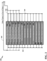
- FIG. 2 illustrates a network storage system (rack) 200 with an IOM configured for use with Ethernet to provide for dis-aggregated switching.
- the network storage system 200 includes, in this particular example, two high port count dis-aggregated switches 202 1 -202 2 , three low port count dis-aggregated switches 203 1 -203 3 , a set of standard servers 204 1 , 204 2 , and 204 3 , a pair of Ethernet attached storage components 206 1 and 2062, and a set of additional switch attached components 208 1 , 208 2 , and 208 3 .
- Data pipes/paths 210 are connected to the dis-aggregated switches 202 1 -202 2 and 203 1 -203 3 to provide input/output from the network storage system 200.
- the dis-aggregated switches 202 1 -202 2 and 203 1 -203 3 are in turn connected via data paths/pipes 214 to one another and to the other components of the rack 200: the standard servers 204 1 , 204 2 , and 204 3 , the Ethernet attached storage components 206 1 and 206 2 , and the additional switch attached components 208 1 , 208 2 , and 208 3 .
- the standard servers 204 1 , 204 2 , and 204 3 the Ethernet attached storage components 206 1 and 206 2
- the additional switch attached components 208 1 , 208 2 , and 208 3 are provided (i.e., one fewer that the rack 100 of FIG. 1 , which does not include dis-aggregated switches).
- the rack 200 can omit the intermediate data pipes/paths.
- the features illustrated in this figure and in the other figures described herein are merely illustrative.
- the number of servers or other components shown in the figures are merely exemplary.
- the number of TOR components of predecessor systems that can be replaced using the systems and architectures described herein are merely exemplary.
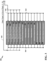
- FIG. 3 illustrates a network storage system (rack) 300 with an IOM configured for use with InfiniBand to provide for dis-aggregated switching.
- the network storage system 300 has an architecture similar to the architecture of network storage system 200 and hence will only briefly be described.
- the network storage system 300 includes, in this particular example, two high port count dis-aggregated switches 302 1 -302 2 , three lowport count dis-aggregated switches 303 1 -303 3 , a set of standard servers 304 1 , 304 2 , and 304 3 , a pair of InfiniBand attached storage components 306 1 and 306 2 , and a set of additional switch attached components 308 1 , 308 2 , and 308 3 .
- Data paths/pipes 314 provide coupling among the components of the rack 300. No separate InfiniBand TOR switches are required.
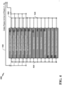
- FIG. 4 illustrates a network storage system (rack) 400 with an IOM configured for use with Fibre Channel to provide for dis-aggregated switching.
- the network storage system 400 has an architecture similar to the architecture of network storage system 200 and hence will only briefly be described.
- the network storage system 400 includes, in this particular example, two high port count dis-aggregated switches 402 1 -402 2 , three low port count dis-aggregated switches 403 1 -403 3 , a set of standard servers 404 1 , 404 2 , and 404 3 , a pair of Fibre channel attached storage components 406 1 and 406 2 , and a set of additional switch attached components 408 1 , 408 2 , and 408 3 .
- Data paths/pipes 414 provide coupling among the components of the rack 400.
- FIG. 5 illustrates a network storage system (rack) 500 with an IOM configured for use with Ethernet, InfiniBand, and Fibre Channel to provide for dis-aggregated switching.
- the network storage system 500 includes, in this particular example, two high port count dis-aggregated switches 502 1 -502 2 , three low port count dis-aggregated switches 503 1 -503 3 , a set of standard servers 504 1 , 504 2 , and 504 3 , an Ethernet attached storage component 506 1 , an InfiniBand attached storage component 506 2 , a Fibre channel attached storage component 506 3 , and a pair of additional switch attached components 508 1 and 508 2 .
- Data pipes/paths 510 to provide input/output from the network storage system 500.
- Data paths/pipes 514 provide coupling among the components of the rack 500.
- the dis-aggregated switches 502 1 -502 2 and 503 1 -503 3 incorporate Ethernet, Fibre Channel and/or InfiniBand Switching with multiple switches per IOM. No separate Ethernet, Fibre Channel and/or InfiniBand TOR switches are required.
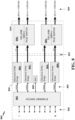
- FIG. 6 is a bock diagram of a general purpose switch card or fabric card 600 incorporating features of the IOMs of FIGS. 2-5 , wherein a BMC is connected to the Ethernet/Fibre channel/InfiniBand switch directly, allowing all switch connected devices to access the BMC without a dedicated management port.
- the fabric card 600 includes an Ethernet/Fibre channel and/or InfiniBand switch 602, an Ethernet/InfiniBand/Fibre Channel-to-high speed serial integrated circuit 604 (which may be a combination of separate integrated circuits (ICs)), and a high speed serial switch 606.
- a BMC 608 is connected to the Ethernet/Fibre channel and/or InfiniBand switch 602.
- a first dashed box 610 corresponds to a configuration for personality module circuitry that collectively incorporates each of the illustrated switch and circuit components.
- a second dashed box 612 corresponds to a configuration for personality module circuitry that incorporates the switch 602, the integrated circuit 604, and the BMC 608 but excludes the high speed serial switch 606.
- a third dashed box 614 corresponds to a configuration for personality module circuitry that incorporates integrated circuit 604, the BMC 608, and the high speed serial switch 606 but excludes the switch 602.
- a fourth dashed box 616 corresponds to a configuration for personality module circuitry that incorporates just the integrated circuit 604.
- FIG. 6 also illustrates exemplary data transfer data pipes or paths (each have N total lanes).
- a set of N Ethernet/Fibre channel and/or InfiniBand lanes 618 connect the Ethernet/Fibre channel and/or InfiniBand switch 602 to external upstream components.
- a set of N high speed serial lanes 620 connect switch 602 to IC 604.
- a set of N high speed serial lanes 622 connect IC 604 to high speed serial switch 606.
- a set of N high speed serial lanes 624 connect high speed serial switch 606 to external downstream components.
- FIG. 7 is a bock diagram of a low port count switch card or fabric card 700 incorporating features of the general purpose IOM fabric card of FIG. 6 for an Ethernet example.
- the low port count device of FIG. 7 is well-suited for expansion (or downstream) enclosures, where limited port counts are required, and may be used as the low port count dis-aggregated switches 303 1 -303 3 of FIG. 3 .
- the low port fabric card 700 includes an Ethernet switch 702, a set of four Ethernet to NVMe bridges 704 1 -704 4 , and a pair of 100 lane "generation 4" PCIe switches 706 1 -706 2 .
- a BMC 708 is connected to the Ethernet switch 702.
- a dashed block 710 indicates that the Ethernet switch 702 and the set of four Ethernet to NVMe bridges 704 1 -704 4 may be configured as one device or chip set.
- the Ethernet switch 702 determines the particular downstream device (e.g., a particular storage drive) for receiving particular portions of input data (e.g., particular data packets) and routes those particular portions of the data to the downstream device. Since the various storage drives are connected to the Ethernet switch 702 via different bridges 704 1 -704 4 , the Ethernet switch 702 determines, as part of its processing, which particular bridge to route particular portions (packets) of the data through.
- the Ethernet switch 702 provides a means for receiving input data in a first protocol from a plurality of input connectors and for determining particular means for bridging from among a plurality of means for bridging to receive particular portions of the input data.
- a dashed block 712 indicates that the PCIe switches 706 1 -706 2 may be configured as another separate device or chip set.
- FIG. 7 also illustrates exemplary data transfer data pipes or paths.
- a set of eight 100 gigabit (Gb) Ethernet lanes 718 connect the Ethernet switch 702 to external upstream components.
- a set of four 100 Gb lanes 720 connect switch 702 to the NVMe bridges 704 1 -704 4 .
- Gb gigabit
- a set of four X16 lanes 722 connect NVMe bridges 704 1 -704 4 to the two PCIe switches 706 1 -706 2 .
- a set of four 28X lanes 724 connect the two PCIe switches 706 1 -706 2 to external downstream components. In the particular example of FIG. 7 , each of the lanes 724 can be coupled to fourteen drives.
- a similar configuration as shown in FIG. 7 can be provided for use with InfiniBand or Fibre Channel. Note that the switches 706 1 -706 2 need not be generation 4 PCIe switches, but other generations, e.g., generation 5 and beyond, or other, non-PCIe switches.
- FIG. 8 is a bock diagram of a high port count switch card or fabric card 800 incorporating features of the general purpose fabric card of FIG. 6 for an Ethernet example.
- the high port count device of FIG. 8 is well-suited for Head (or upstream) enclosures, where the TOR functionality is being replaced, and may be used as the high port count dis-aggregated switches 302 1 -302 2 of FIG. 3 . (Both low and high port count switches may be used in overall systems as shown in FIG. 3 )
- the high port fabric card 800 includes an Ethernet switch 802, a set of four Ethernet to NVMe bridges 804 1 -804 4 , and a pair of 100 lane "generation 4" PCIe switches 806 1 -806 2 .
- a BMC 808 is connected to the Ethernet switch 802.
- a dashed block 810 indicates that the Ethernet switch 802 and the set of Ethernet to NVMe bridges 804 1 -804 4 may be configured as one device or chip set.
- a dashed block 812 indicates that the PCIe switches 806 1 -806 2 may be configured as another separate device or chip set.
- FIG. 8 also illustrates exemplary data transfer data pipes or paths.
- a set of N 100 Gb Ethernet lanes 818 connect the Ethernet switch 802 to external upstream components.
- a set of four 100 Gb lanes 820 connect switch 802 to the NVMe bridges 804 1 -804 4 .
- a set of four X16 lanes 822 connect NVMe bridges 804 1 -804 4 to the two PCIe switches 806 1 -806 2 .
- a set of four 28X lanes 824 connect the two PCIe switches 806 1 -806 2 to external downstream components. In the particular example of FIG. 8 , each of the 28X lanes 824 can be coupled to fourteen NVM drives.
- the low port count example of FIG. 7 provides for eight connections into the Ethernet switch 702
- the high port count example of FIG. 8 provides for N connections into the Ethernet switch 802 (where N can be any practical number but is typically substantially larger than 8 and, in some examples, may be 96).
- a BMC need not be provided and so, in some implementations, a device with all of the components of FIG. 8 may be provided while omitting the BMC or incorporating the BMC functionality into other components.
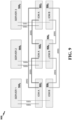
- FIG. 9 illustrates a low port count system 900 that includes six IOMs.
- Three of the IOMs denoted IOM A 902 1 -902 3 , are connected to one another and to a set of three servers 904 1 -904 3 via the various connection lines/paths shown in the figure.
- the other three of the IOMs denoted IOM B 906 1 -906 3 , are connected to one another and to the set of three servers 904 1 -904 3 via the various connection lines/paths shown in the figure, some of which are 100G connectors (where G is another designator for gigabit (Gb)) and others are 200G connectors, such as Ethernet connectors.
- G is another designator for gigabit (Gb)
- 200G connectors such as Ethernet connectors.
- a mezzanine card may be plugged onto the base IOM of a system to enable a carrier/switch board to support any available device back end.
- the IOM may support high-speed switch (Fibre Channel, Ethernet of InfiniBand) connections from the switch to a connector system (mezzanine, back plane, card edge of SODIMM style) and a similar connector system that allows the card to interface to the system.
- This personality module functionality can be populated as a mezzanine style card using any of the connector systems described above.
- the mezzanine connector system thus allows a "personality module" to be connected between the back end device interface and the front-end switch system so as to provide a configurable interface system that supports a protocol agnostic enclosure. Note also that single board and multiple board implementations are provided (to provide the configurable interface system that supports the protocol agnostic enclosure).
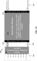
- the switch may have N ports 1018 for use as a host interface.
- the first mezzanine connection 1006 may accommodate an equal number of high speed serial lanes 1020 for connecting to the switch 2001.
- the second mezzanine connection 1008 may accommodate an equal number of high speed serial lanes 1024 for connecting to the other components (via, for example, a midplane/driveplane connector, discussed below).
- the switch fabric may be configured on an IOM PCBA (with the IOM PCBA shown in FIG. 12 ).
- FIG. 11 illustrates a second exemplary protocol agnostic IOM 1100, which includes a switch (Ethernet, InfiniBand, or Fibre Channel) 1102 and a personality module 1104.
- the personality module 1104 may include, for example, various CPU, GPU, NIC, SAS, SATA, RAID, Ethernet, NVMe, Fibre Channel, InfiniBand, any protocol or compute interface components so as to provide a protocol agnostic system that can accommodate a wide variety of protocols).
- a first mezzanine connection 1106 is provided between the switch 1002 and its N connection lines 1118.
- a second mezzanine connection 1108 is provided on the personality module 1104 for connecting the personality module 1104 to other components (not shown).
- the personality module 1104 may accommodate an equal number of high speed serial lanes 1120 for connecting to the switch 1002.
- the second mezzanine connection 1108 may accommodate an equal number of high speed serial lanes 1124 for connecting to the other components.
- the switch fabric may be configured with switch circuitry on a personality module card (with the PM card shown in FIG. 12 ).
- FIG. 12 illustrates a two examples of the physical structure of a protocol agnostic IOM that includes a personality module as shown in FIGS. 10 and 11 .
- a personality module card 1202 is mounted co-planar with an IOM PCBA 1204 (i.e., mounted over the IOM PCBA and parallel with the IOM PCBA).
- a pair of mezzanine connectors 1206 and 1208 e.g., connectors 1006 and 1008 of FIG. 10 ) connect the personality module card 1202 to the IOM PCBA 1204.
- a 1... N host interface connector 1210 is provided on one end of the IOM PCBA 1204.
- a midplane/driveplane connector 1212 is provided at the other end of the IOM PCBA 1204, which may provide N high speed serial lanes (as shown in FIG. 10 ).
- a personality module card 1252 is mounted perpendicular to an IOM PCBA 1254.
- a pair of mezzanine connectors 1256 and 1258 (e.g., connectors 1006 and 1008 of FIG. 10 ) connect opposing sides of the personality module card 1252 to the IOM PCBA 1254.
- a 1... N host interface connector 1260 is again provided on one end of the IOM PCBA 1254.
- a midplane/driveplane connector 1262 is again provided at the other end of the IOM PCBA 1254, which may provide N high speed serial lanes (as shown in FIG. 10 ).
- FIG. 13 illustrates another co-planar physical structure 1300 having a personality module card 1302 mounted co-planar with an IOM PCBA 1304.
- a card edge connector 1306 connects the personality module card 1302 to the IOM PCBA 1304.
- a 1...N host interface connector 1310 is provided on one end of the IOM PCBA 1304.
- a midplane/driveplane connector 1312 is provided at the other end of the IOM PCBA 1304, which may provide N high speed serial lanes (as shown in FIGS. 10 and 12 ).
- the card edge connector 1306 can be at a right angle with the personality module 1302 and mounted in space above the IOM PCBA 1304.
- the card edge connector 1306 can be co-planar with the personality module card 1302 mounted in a cut out in the IOM PCBA 1304.
- the switch chip (e.g., Ethernet, Fibre Channel or InfiniBand) may be populated onto a PCIe plug in card and may be used in connection with industry standard form factor (e.g., HHHL, FHHL, FHFL, HHFL) as well as non-industry standard form factors.
- the PCIe plug in card may be used a true switch, not a NIC (Network Interface Card).
- NIC Network Interface Card
- other implementations are often intended to be host ports to provide data connections to a server or host device and are typically connected to the PCIe bus to provide data to the host over that bus.
- the switch card obtains its power from the PCIe slot.
- the switch thus operates as a stand-alone switch, primarily receiving power from the PCIe slot. No connections over the PCIe lanes are needed. Auxiliary data management connections may be made within the PCIe slot but (in at least some examples) the auxiliary data management connections are for environmental management only.
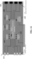
- FIG. 14 illustrates an exemplary physical structure for a PCIe-based switch module PCBA 1400.
- the switch module PCBA 1400 includes a switch 1402 (e.g., Ethernet, InfiniBand, or Fibre Channel) mounted in the center of the PCBA 1400, with various additional devices also mounted to the PCBA 1400.
- the additional devices include a power control and conversion device 1404, a monitoring device 1406 for monitoring signals, and supporting circuitry 1408, 1410, and 1412.
- Various interconnection lines are shown that connect the components to one another and to input/output connectors, including a set of 1... N host connectors 1414 and a set of 1... N internal switch port connectors 1416.
- FIG. 15 illustrates another exemplary physical structure for a PCIe-based switch module PCBA 1500.
- the switch module PCBA 1500 includes a switch 1502 (e.g., Ethernet, InfiniBand, or Fibre Channel) mounted in the center of the PCBA 1500, with various additional devices also mounted to the PCBA 1500.
- the additional devices are generally represented as supporting circuitry 1504.
- Interconnection lines are not shown in the illustration of FIG. 15 , but similar connections as in FIG. 14 may be used to connect the various components to one another and to input/output connectors, including a set of 1... N host connectors 1514 and a set of 1... N internal switch port connectors 1516.
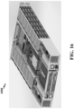
- FIG. 16 is a perspective view of an exemplary embodiment of a fabric box 1600 with an integrated switch which may be configured in accordance with the various features of FIGS. 2-15 , discussed above. Switch ports are integrated into the fabric modules. The device distributed switching through the rack system (not shown) it is installed in, and eliminates the need for a TOR switch (of the type shown in FIG. 1 ).
- FIG. 17 is a block diagram illustrating an IOM 1700 for use within a network storage system.
- the IOM 1700 includes a switching component 1702 configured to provide TOR switching for data to be routed from input connectors to one or more storage devices within a rack enclosure.
- the IOM 1700 also includes a protocol interface 1704 configured to convert a protocol of the data from an input data protocol to a protocol for use with the one of more storage devices within the rack enclosure. Examples of these components are described above in detail above with reference to FIGS. 1-16 .
- the network storage system may be a rack-based system wherein the various components of the system, including the IOM 1700 and the various storage devices, are mounted within the enclosure of the rack.
- FIG. 18 is a flow chart illustrating a method 1800 that may be performed by the IOM 1700 of FIG. 17 or other suitably-equipped systems, devices or apparatus.
- an IOM of a network storage system routes data through a switching component of the IOM that is configured to provide TOR switching of the data to determine a particular device destination for the data within the network storage system.
- the IOM then routes the data through a protocol interface of the IOM that is configured to convert a protocol of the data from an input data protocol to a protocol for use with the particular device destination of the data.
- the switching component may be, for example, switching component 1702 of FIG. 17 and the protocol interface may be, for example, the protocol interface 1704 of FIG. 17 . Examples of the operations of FIG. 18 are described in greater detail with reference to FIGS. 1-17 .
- FIG. 19 is a flow chart further illustrating a method 1900 that may be performed by the IOM 1700 of FIG. 17 or other suitably-equipped systems, devices or apparatus.
- an IOM of a rack-based network storage system routes data through a switching component of the IOM that is configured to provide TOR switching of Ethernet, Fibre Channel and/or InfiniBand protocol data to determine a particular device destination for the data within the network storage system, such as a particular protocol-specific storage component, server, or switch attached components (mounted within a rack enclosure) that uses nonvolatile memory express (NVMe) and/or Peripheral Component Interconnect Express (PCIe) or other protocols.
- NVMe nonvolatile memory express
- PCIe Peripheral Component Interconnect Express
- the IOM routes data through a switching component of the IOM that is configured to provide TOR switching of the data to determine a particular device destination for the data within the network storage system.
- the IOM then routes the data through a protocol interface of the IOM that is configured to convert the protocol of the data (Ethernet, Fibre Channel and/or InfiniBand) to a protocol for use with the particular device destination of the data, such as NVMe and/or PCIe or other protocols.
- the switching component may be, for example, switching component 1702 of FIG. 17 and the protocol interface may be, for example, the protocol interface 1704 of FIG. 17 . Examples of the operations of FIG. 19 are described in detail above with reference to FIGS. 1-16 .
- FIG. 20 is a block diagram illustrating an IOM 2000 for use within a network storage system.
- the IOM 2000 includes a first switching component 2002 configured to receive input data from a plurality of input connectors for routing to a plurality of storage devices of the network storage system and further configured to determine particular bridge components from among a plurality of bridge components to receive particular portions of the input data.
- the IOM 2000 also includes a plurality of bridge components 2004 configured to receive data from the first switching component 2002 in a first protocol and convert the data to a second protocol for use with particular storage devices of the plurality of storage devices.
- the IOM 2000 also includes at least one second switching component 2006 configured to receive data in the second protocol from at least one of the plurality of bridge components 2004 for routing to particular storage devices among the plurality of storage devices.
Landscapes
- Engineering & Computer Science (AREA)
- Theoretical Computer Science (AREA)
- General Engineering & Computer Science (AREA)
- Physics & Mathematics (AREA)
- General Physics & Mathematics (AREA)
- Computer Networks & Wireless Communication (AREA)
- Signal Processing (AREA)
- Human Computer Interaction (AREA)
- Computer Hardware Design (AREA)
- Microelectronics & Electronic Packaging (AREA)
- Mathematical Physics (AREA)
- Small-Scale Networks (AREA)
Claims (17)
- Eingangs-/Ausgangsmodul, EAM, (1100), das dafür konfiguriert ist, in einen Montageschlitz eines Rack-Gehäuses eines Netzwerk-Speichersystems eingesetzt zu sein, wobei das EAM Folgendes umfasst:eine erste Schaltkomponente (702), die dafür konfiguriert ist, Eingangsdaten von mehreren Eingangsverbindern zu empfangen, um sie zu mehreren Speichervorrichtungen (724) des Netzwerk-Speichersystems zu routen,mehrere Brückenkomponenten (704_1-704_4), die dafür konfiguriert sind, Daten von der ersten Schaltkomponente in einem ersten Protokoll zu empfangen und die Daten in ein zweites Protokoll für bestimmte Speichervorrichtungen der mehreren Speichervorrichtungen umzuwandeln,wobei die erste Schaltkomponente dafür konfiguriert ist, bestimmte Brückenkomponenten aus den mehreren Brückenkomponenten zu bestimmen, um bestimmte Teile der Eingangsdaten zu empfangen,mindestens eine zweite Schaltkomponente (706), die dafür konfiguriert ist, Daten in dem zweiten Protokoll von mindestens einer der mehreren Brückenkomponenten zu empfangen, um sie zu bestimmten Speichervorrichtungen aus den mehreren Speichervorrichtungen zu routen, undeinen Baseboard-Management-Controller, BMC, (608, 708, 808), der direkt mit der ersten Schaltkomponente verbunden ist.
- EAM nach Anspruch 1, wobei die erste Speicherkomponente einen Switch mit hoher Portanzahl umfasst, der dafür konfiguriert ist, Top-Of-Rack-, TOR-, Schalten bereitzustellen.
- EAM nach Anspruch 2, wobei der Switch mit hoher Portanzahl einen Switch mit einer Anzahl von Eingangsports im Bereich von neun bis sechsundneunzig aufweist.
- EAM nach Anspruch 1, wobei die erste Schaltkomponente einen Switch mit niedriger Portanzahl umfasst, der dafür konfiguriert ist, Verbindungsfähigkeit bereitzustellen.
- EAM nach Anspruch 4, wobei der Switch mit niedriger Portanzahl einen Switch mit bis zu acht Eingangsports umfasst.
- EAM nach Anspruch 1, wobei die erste Schaltkomponente eines oder mehreres von einem Ethernet-Switch, einem Faserkanal-Switch und einem InfiniBand-Switch umfasst.
- EAM nach Anspruch 6, wobei die mehreren Brückenkomponenten eine oder mehrere von einer Brücke von Ethernet zu Nonvolatile Memory Express, NVMe, einer Brücke von Faserkanal zu NVMe und einer Brücke von InfiniBand zu NVMe umfassen.
- EAM nach Anspruch 1, wobei die mindestens eine zweite Schaltkomponente einen Peripheral-Component-Interconnect-Express-, PCIe-, Switch umfasst und/oder wobei die mehreren Speichervorrichtungen Folgendes umfassen: protokollspezifische Speicherkomponenten, Server oder an Switches angebrachte Komponenten innerhalb des Rack-Gehäuses.
- EAM nach Anspruch 1, wobeiwobei die Eingangsverbinder der ersten Schaltkomponente dafür konfiguriert sind, mit einer Eingangsdaten-Pipe zu verbinden, die Datenkanäle gemäß dem ersten Protokoll bereitstellt,wobei mindestens eine der Brückenkomponenten einen seriellen Hochgeschwindigkeitswandler mit seriellen Lane-Verbindern aufweist, die an die erste Schaltkomponente angeschlossen sind, undwobei die zweite Schaltkomponente einen seriellen Hochgeschwindigkeitsswitch mit seriellen Lane-Verbindern, die an die mindestens eine der Brückenkomponenten angeschlossen sind, um Daten in dem zweiten Protokoll zu empfangen, und mit seriellen Hochgeschwindigkeits-Lane-Verbindern umfasst, um die Daten in dem zweiten Protokoll zu mindestens einer der mehreren Speichervorrichtungen zu routen.
- EAM nach Anspruch 1, wobei die Brückenkomponenten und die zweite Schaltkomponente zusammen ein Personality-Modul (1004, 1104) umfassen.
- EAM nach Anspruch 10, wobei das Personality-Modul als eine Mezzanine-Card konfiguriert ist und einen oder mehrere Mezzanine-Verbinder umfasst.
- EAM nach Anspruch 10, wobei das Personality-Modul zwischen einem ersten Mezzanine-Verbinder und einem zweiten Mezzanine-Verbinder angeschlossen ist.
- EAM nach Anspruch 10, wobei der erste Switch zwischen dem ersten Mezzanine-Verbinder und dem Personality-Modul angeschlossen ist.
- EAM nach Anspruch 11, wobei die Mezzanine-Card für koplanares Montieren an einer bestückten Leiterplatte, PCBA, konfiguriert ist, welche die erste Schaltkomponente beinhaltet, und/oder wobei die Mezzanine-Card für vertikales Montieren an einer PCBA konfiguriert ist, welche die erste Schaltkomponente beinhaltet.
- Verfahren zur Verwendung in einem Eingangs-/Ausgangsmodul, EAM, (1100) zum Einsetzen in einen Montageschlitz eines Rack-Gehäuses eines Netzwerk-Speichersystems, wobei das Verfahren Folgendes umfasst:Routen von Daten durch eine erste Schaltkomponente (702), die dafür konfiguriert ist, Eingangsdaten in einem ersten Protokoll von mehreren Eingangsverbindern zu empfangen, um sie zu mehreren Speichervorrichtungen (724) des Netzwerk-Speichersystem zu routen,Bestimmen bestimmter Brückenkomponenten (704) aus mehreren Brückenkomponenten (704_1-704_4), um bestimmte Teile der Eingangsdaten zu empfangen,Routen der bestimmten Teil der Eingangsdaten durch mindestens eine der mehreren Brückenkomponenten, um die Eingangsdaten in ein zweites Protokoll zur Verwendung mit bestimmten Speichervorrichtungen der mehreren Speichervorrichtungen umzuwandeln,Routen der Daten in dem zweiten Protokoll durch mindestens eine zweite Schaltkomponente (706) zum Senden an bestimmte Speichervorrichtungen der mehreren Speichervorrichtungen undZugreifen auf einen Baseboard-Management-Controller, BMC, (608, 708, 808), der direkt mit der ersten Schaltkomponente verbunden ist.
- Verfahren nach Anspruch 14, wobei die erste Schaltkomponente für die Verwendung mit einem oder mehreren von Ethernet, Faserkanal und InfiniBand konfiguriert ist und wobei das Routen der bestimmten Teile der Eingangsdaten durch die mindestens eine der Brückenkomponenten durchgeführt wird, um die Daten von einem bestimmten von Ethernet, Faserkanal und InfiniBand in das zweite Protokoll zur Verwendung mit einer bestimmten der Speichervorrichtungen umzuwandeln, und/oder wobei das zweite Protokoll eines oder mehrere von NVMe, Nonvolatile Memory Express, und PCIe, Peripheral Component Interconnect Express, umfasst.
- Verfahren nach Anspruch 14 oder 15,wobei das Routen der Daten durch die erste Schaltkomponente das Empfangen der Daten von einer Eingangsdaten-Pipe umfasst, die Datenkanäle gemäß dem ersten Protokoll bereitstellt,wobei das Routen der Daten durch mindestens eine der Brückenkomponenten das Routen der Daten durch einen seriellen Hochgeschwindigkeitswandler mit seriellen Lane-Verbindern aufweist, die an die erste Speicherkomponente angeschlossen sind, umfasst undwobei das Routen der Daten durch die zweite Schaltkomponente das Routen der Daten in dem zweiten Protokoll durch einen seriellen Hochgeschwindigkeits-Switch mit seriellen Lane-Verbindern, die an die mindestens eine der Brückenkomponenten angeschlossen sind, umfasst.
Applications Claiming Priority (1)
| Application Number | Priority Date | Filing Date | Title |
|---|---|---|---|
| US17/515,004 US12132670B2 (en) | 2021-10-29 | 2021-10-29 | Dis-aggregated switching and protocol configurable input/output module |
Publications (3)
| Publication Number | Publication Date |
|---|---|
| EP4174667A1 EP4174667A1 (de) | 2023-05-03 |
| EP4174667B1 true EP4174667B1 (de) | 2024-12-25 |
| EP4174667C0 EP4174667C0 (de) | 2024-12-25 |
Family
ID=84047587
Family Applications (1)
| Application Number | Title | Priority Date | Filing Date |
|---|---|---|---|
| EP22204826.6A Active EP4174667B1 (de) | 2021-10-29 | 2022-10-31 | Disaggregiertes schalt- und protokollkonfigurierbares eingangs-/ausgangsmodul |
Country Status (2)
| Country | Link |
|---|---|
| US (2) | US12132670B2 (de) |
| EP (1) | EP4174667B1 (de) |
Families Citing this family (1)
| Publication number | Priority date | Publication date | Assignee | Title |
|---|---|---|---|---|
| US20260105018A1 (en) * | 2024-10-13 | 2026-04-16 | One Stop Systems, Inc. | Adapting open compute project to support sensor i/o standards |
Family Cites Families (12)
| Publication number | Priority date | Publication date | Assignee | Title |
|---|---|---|---|---|
| US7274660B2 (en) | 2002-08-15 | 2007-09-25 | Motorola, Inc. | Method of flow control |
| US7295519B2 (en) | 2003-06-20 | 2007-11-13 | Motorola, Inc. | Method of quality of service based flow control within a distributed switch fabric network |
| JP4514501B2 (ja) * | 2004-04-21 | 2010-07-28 | 株式会社日立製作所 | ストレージシステム及びストレージシステムの障害解消方法 |
| US8599863B2 (en) * | 2009-10-30 | 2013-12-03 | Calxeda, Inc. | System and method for using a multi-protocol fabric module across a distributed server interconnect fabric |
| US10877695B2 (en) * | 2009-10-30 | 2020-12-29 | Iii Holdings 2, Llc | Memcached server functionality in a cluster of data processing nodes |
| US8504755B2 (en) * | 2010-03-03 | 2013-08-06 | Plx Technology, Inc. | USB 3 bridge with embedded hub |
| US8366464B1 (en) * | 2011-08-25 | 2013-02-05 | Dell Products L.P. | Retraction arm to extract a mezzanine circuit board connector from a motherboard connector |
| US10162793B1 (en) * | 2015-09-29 | 2018-12-25 | Amazon Technologies, Inc. | Storage adapter device for communicating with network storage |
| US11546992B2 (en) * | 2017-08-07 | 2023-01-03 | Sanmina Corporation | Modular motherboard for a computer system and method thereof |
| US20190187909A1 (en) * | 2017-12-20 | 2019-06-20 | Samsung Electronics Co., Ltd. | Local management console for storage devices |
| US20210027313A1 (en) * | 2019-07-25 | 2021-01-28 | Dell Products L.P. | Data Representations for a Sales Facilitation Operation |
| US11895027B2 (en) | 2021-05-20 | 2024-02-06 | Pensando Systems Inc. | Methods and systems for service distribution using data path state replication and intermediate device mapping |
-
2021
- 2021-10-29 US US17/515,004 patent/US12132670B2/en active Active
-
2022
- 2022-10-31 EP EP22204826.6A patent/EP4174667B1/de active Active
-
2024
- 2024-09-24 US US18/895,065 patent/US20250016118A1/en active Pending
Also Published As
| Publication number | Publication date |
|---|---|
| EP4174667A1 (de) | 2023-05-03 |
| US12132670B2 (en) | 2024-10-29 |
| US20250016118A1 (en) | 2025-01-09 |
| US20230137940A1 (en) | 2023-05-04 |
| EP4174667C0 (de) | 2024-12-25 |
Similar Documents
| Publication | Publication Date | Title |
|---|---|---|
| US7315456B2 (en) | Configurable IO subsystem | |
| US7783818B1 (en) | Modularized interconnect between root complexes and I/O modules | |
| US7983194B1 (en) | Method and system for multi level switch configuration | |
| US20040083324A1 (en) | Large array of mass data storage devices connected to a computer by a serial link | |
| US20170300445A1 (en) | Storage array with multi-configuration infrastructure | |
| US20150092788A1 (en) | Input-output module | |
| US10925167B2 (en) | Modular expansion card bus | |
| TWI603202B (zh) | 具有通道資源重定向的設備及系統 | |
| US20190045634A1 (en) | Modular motherboard for a computer system and method thereof | |
| US20040023558A1 (en) | Mid-connect architecture with point-to-point connections for high speed data transfer | |
| CN115481068B (zh) | 服务器及数据中心 | |
| CN102918815B (zh) | 高级电信计算架构数据交换系统及交换板、数据交换方法 | |
| US20250016118A1 (en) | Dis-aggregated switching and protocol configurable input/output module | |
| US20080123552A1 (en) | Method and system for switchless backplane controller using existing standards-based backplanes | |
| Schares et al. | Optics in future data center networks | |
| US7102893B1 (en) | Methods and apparatus for forming a cohesive backplane interconnect system | |
| US20030002541A1 (en) | Mid-connect architecture with point-to-point connections for high speed data transfer | |
| US11693812B2 (en) | Multi-host networking systems and methods | |
| US10237204B2 (en) | Switch chassis with flexible topology | |
| US20260030192A1 (en) | Circuit Board of Graphics Processing Unit and Server System | |
| KR20220162093A (ko) | 복수의 전자 구성요소에 대한 네트워크 인터페이스 제공 시스템 | |
| EP1415234B1 (de) | Serverlets mit hoher dichte mittels hochgeschwindigkeits-datenbus | |
| CN222050884U (zh) | 一种扩展卡 | |
| CN120315534B (zh) | 电路板 | |
| US20060059288A1 (en) | Reduced speed I/O from rear transition module |
Legal Events
| Date | Code | Title | Description |
|---|---|---|---|
| PUAI | Public reference made under article 153(3) epc to a published international application that has entered the european phase |
Free format text: ORIGINAL CODE: 0009012 |
|
| STAA | Information on the status of an ep patent application or granted ep patent |
Free format text: STATUS: THE APPLICATION HAS BEEN PUBLISHED |
|
| AK | Designated contracting states |
Kind code of ref document: A1 Designated state(s): AL AT BE BG CH CY CZ DE DK EE ES FI FR GB GR HR HU IE IS IT LI LT LU LV MC ME MK MT NL NO PL PT RO RS SE SI SK SM TR |
|
| STAA | Information on the status of an ep patent application or granted ep patent |
Free format text: STATUS: REQUEST FOR EXAMINATION WAS MADE |
|
| 17P | Request for examination filed |
Effective date: 20231103 |
|
| RBV | Designated contracting states (corrected) |
Designated state(s): AL AT BE BG CH CY CZ DE DK EE ES FI FR GB GR HR HU IE IS IT LI LT LU LV MC ME MK MT NL NO PL PT RO RS SE SI SK SM TR |
|
| GRAP | Despatch of communication of intention to grant a patent |
Free format text: ORIGINAL CODE: EPIDOSNIGR1 |
|
| STAA | Information on the status of an ep patent application or granted ep patent |
Free format text: STATUS: GRANT OF PATENT IS INTENDED |
|
| INTG | Intention to grant announced |
Effective date: 20240722 |
|
| GRAS | Grant fee paid |
Free format text: ORIGINAL CODE: EPIDOSNIGR3 |
|
| GRAA | (expected) grant |
Free format text: ORIGINAL CODE: 0009210 |
|
| STAA | Information on the status of an ep patent application or granted ep patent |
Free format text: STATUS: THE PATENT HAS BEEN GRANTED |
|
| AK | Designated contracting states |
Kind code of ref document: B1 Designated state(s): AL AT BE BG CH CY CZ DE DK EE ES FI FR GB GR HR HU IE IS IT LI LT LU LV MC ME MK MT NL NO PL PT RO RS SE SI SK SM TR |
|
| REG | Reference to a national code |
Ref country code: GB Ref legal event code: FG4D |
|
| REG | Reference to a national code |
Ref country code: CH Ref legal event code: EP |
|
| REG | Reference to a national code |
Ref country code: DE Ref legal event code: R096 Ref document number: 602022009071 Country of ref document: DE |
|
| REG | Reference to a national code |
Ref country code: IE Ref legal event code: FG4D |
|
| U01 | Request for unitary effect filed |
Effective date: 20250125 |
|
| U07 | Unitary effect registered |
Designated state(s): AT BE BG DE DK EE FI FR IT LT LU LV MT NL PT RO SE SI Effective date: 20250131 |
|
| PG25 | Lapsed in a contracting state [announced via postgrant information from national office to epo] |
Ref country code: HR Free format text: LAPSE BECAUSE OF FAILURE TO SUBMIT A TRANSLATION OF THE DESCRIPTION OR TO PAY THE FEE WITHIN THE PRESCRIBED TIME-LIMIT Effective date: 20241225 |
|
| PG25 | Lapsed in a contracting state [announced via postgrant information from national office to epo] |
Ref country code: NO Free format text: LAPSE BECAUSE OF FAILURE TO SUBMIT A TRANSLATION OF THE DESCRIPTION OR TO PAY THE FEE WITHIN THE PRESCRIBED TIME-LIMIT Effective date: 20250325 |
|
| PG25 | Lapsed in a contracting state [announced via postgrant information from national office to epo] |
Ref country code: GR Free format text: LAPSE BECAUSE OF FAILURE TO SUBMIT A TRANSLATION OF THE DESCRIPTION OR TO PAY THE FEE WITHIN THE PRESCRIBED TIME-LIMIT Effective date: 20250326 |
|
| PG25 | Lapsed in a contracting state [announced via postgrant information from national office to epo] |
Ref country code: RS Free format text: LAPSE BECAUSE OF FAILURE TO SUBMIT A TRANSLATION OF THE DESCRIPTION OR TO PAY THE FEE WITHIN THE PRESCRIBED TIME-LIMIT Effective date: 20250325 |
|
| PG25 | Lapsed in a contracting state [announced via postgrant information from national office to epo] |
Ref country code: SM Free format text: LAPSE BECAUSE OF FAILURE TO SUBMIT A TRANSLATION OF THE DESCRIPTION OR TO PAY THE FEE WITHIN THE PRESCRIBED TIME-LIMIT Effective date: 20241225 |
|
| PG25 | Lapsed in a contracting state [announced via postgrant information from national office to epo] |
Ref country code: PL Free format text: LAPSE BECAUSE OF FAILURE TO SUBMIT A TRANSLATION OF THE DESCRIPTION OR TO PAY THE FEE WITHIN THE PRESCRIBED TIME-LIMIT Effective date: 20241225 |
|
| PG25 | Lapsed in a contracting state [announced via postgrant information from national office to epo] |
Ref country code: ES Free format text: LAPSE BECAUSE OF FAILURE TO SUBMIT A TRANSLATION OF THE DESCRIPTION OR TO PAY THE FEE WITHIN THE PRESCRIBED TIME-LIMIT Effective date: 20241225 |
|
| PG25 | Lapsed in a contracting state [announced via postgrant information from national office to epo] |
Ref country code: IS Free format text: LAPSE BECAUSE OF FAILURE TO SUBMIT A TRANSLATION OF THE DESCRIPTION OR TO PAY THE FEE WITHIN THE PRESCRIBED TIME-LIMIT Effective date: 20250425 |
|
| PG25 | Lapsed in a contracting state [announced via postgrant information from national office to epo] |
Ref country code: SK Free format text: LAPSE BECAUSE OF FAILURE TO SUBMIT A TRANSLATION OF THE DESCRIPTION OR TO PAY THE FEE WITHIN THE PRESCRIBED TIME-LIMIT Effective date: 20241225 |
|
| PG25 | Lapsed in a contracting state [announced via postgrant information from national office to epo] |
Ref country code: CZ Free format text: LAPSE BECAUSE OF FAILURE TO SUBMIT A TRANSLATION OF THE DESCRIPTION OR TO PAY THE FEE WITHIN THE PRESCRIBED TIME-LIMIT Effective date: 20241225 |
|
| U20 | Renewal fee for the european patent with unitary effect paid |
Year of fee payment: 4 Effective date: 20250909 |
|
| PLBE | No opposition filed within time limit |
Free format text: ORIGINAL CODE: 0009261 |
|
| STAA | Information on the status of an ep patent application or granted ep patent |
Free format text: STATUS: NO OPPOSITION FILED WITHIN TIME LIMIT |
|
| 26N | No opposition filed |
Effective date: 20250926 |