EP4174547A1 - Cable composite - Google Patents
Cable composite Download PDFInfo
- Publication number
- EP4174547A1 EP4174547A1 EP22203549.5A EP22203549A EP4174547A1 EP 4174547 A1 EP4174547 A1 EP 4174547A1 EP 22203549 A EP22203549 A EP 22203549A EP 4174547 A1 EP4174547 A1 EP 4174547A1
- Authority
- EP
- European Patent Office
- Prior art keywords
- cable
- cables
- cable assembly
- sub
- assembly
- Prior art date
- Legal status (The legal status is an assumption and is not a legal conclusion. Google has not performed a legal analysis and makes no representation as to the accuracy of the status listed.)
- Pending
Links
- 239000002131 composite material Substances 0.000 title claims abstract description 57
- 239000000835 fiber Substances 0.000 claims description 34
- 238000004891 communication Methods 0.000 claims description 29
- 239000004033 plastic Substances 0.000 claims description 21
- 229920003023 plastic Polymers 0.000 claims description 21
- 230000005540 biological transmission Effects 0.000 claims description 11
- 239000003365 glass fiber Substances 0.000 claims description 9
- 239000004698 Polyethylene Substances 0.000 claims description 3
- 239000013307 optical fiber Substances 0.000 claims description 3
- -1 polyethylene Polymers 0.000 claims description 3
- 229920000573 polyethylene Polymers 0.000 claims description 3
- 239000000243 solution Substances 0.000 description 11
- 238000010276 construction Methods 0.000 description 9
- 239000000463 material Substances 0.000 description 9
- 238000000034 method Methods 0.000 description 6
- 238000011161 development Methods 0.000 description 4
- 230000018109 developmental process Effects 0.000 description 4
- 238000007664 blowing Methods 0.000 description 3
- 230000003287 optical effect Effects 0.000 description 3
- 230000003993 interaction Effects 0.000 description 2
- 238000009412 basement excavation Methods 0.000 description 1
- 230000001419 dependent effect Effects 0.000 description 1
- 230000007613 environmental effect Effects 0.000 description 1
- 230000002349 favourable effect Effects 0.000 description 1
- 230000009993 protective function Effects 0.000 description 1
- 230000008054 signal transmission Effects 0.000 description 1
- 239000002689 soil Substances 0.000 description 1
- 230000007704 transition Effects 0.000 description 1
Images


Classifications
-
- G—PHYSICS
- G02—OPTICS
- G02B—OPTICAL ELEMENTS, SYSTEMS OR APPARATUS
- G02B6/00—Light guides; Structural details of arrangements comprising light guides and other optical elements, e.g. couplings
- G02B6/46—Processes or apparatus adapted for installing or repairing optical fibres or optical cables
- G02B6/50—Underground or underwater installation; Installation through tubing, conduits or ducts
- G02B6/504—Installation in solid material, e.g. underground
-
- H—ELECTRICITY
- H02—GENERATION; CONVERSION OR DISTRIBUTION OF ELECTRIC POWER
- H02G—INSTALLATION OF ELECTRIC CABLES OR LINES, OR OF COMBINED OPTICAL AND ELECTRIC CABLES OR LINES
- H02G1/00—Methods or apparatus specially adapted for installing, maintaining, repairing or dismantling electric cables or lines
- H02G1/06—Methods or apparatus specially adapted for installing, maintaining, repairing or dismantling electric cables or lines for laying cables, e.g. laying apparatus on vehicle
-
- H—ELECTRICITY
- H02—GENERATION; CONVERSION OR DISTRIBUTION OF ELECTRIC POWER
- H02G—INSTALLATION OF ELECTRIC CABLES OR LINES, OR OF COMBINED OPTICAL AND ELECTRIC CABLES OR LINES
- H02G9/00—Installations of electric cables or lines in or on the ground or water
- H02G9/02—Installations of electric cables or lines in or on the ground or water laid directly in or on the ground, river-bed or sea-bottom; Coverings therefor, e.g. tile
-
- G—PHYSICS
- G02—OPTICS
- G02B—OPTICAL ELEMENTS, SYSTEMS OR APPARATUS
- G02B6/00—Light guides; Structural details of arrangements comprising light guides and other optical elements, e.g. couplings
- G02B6/44—Mechanical structures for providing tensile strength and external protection for fibres, e.g. optical transmission cables
- G02B6/4401—Optical cables
- G02B6/441—Optical cables built up from sub-bundles
-
- G—PHYSICS
- G02—OPTICS
- G02B—OPTICAL ELEMENTS, SYSTEMS OR APPARATUS
- G02B6/00—Light guides; Structural details of arrangements comprising light guides and other optical elements, e.g. couplings
- G02B6/44—Mechanical structures for providing tensile strength and external protection for fibres, e.g. optical transmission cables
- G02B6/4401—Optical cables
- G02B6/4429—Means specially adapted for strengthening or protecting the cables
- G02B6/443—Protective covering
- G02B6/4431—Protective covering with provision in the protective covering, e.g. weak line, for gaining access to one or more fibres, e.g. for branching or tapping
-
- G—PHYSICS
- G02—OPTICS
- G02B—OPTICAL ELEMENTS, SYSTEMS OR APPARATUS
- G02B6/00—Light guides; Structural details of arrangements comprising light guides and other optical elements, e.g. couplings
- G02B6/44—Mechanical structures for providing tensile strength and external protection for fibres, e.g. optical transmission cables
- G02B6/4439—Auxiliary devices
- G02B6/4459—Ducts; Conduits; Hollow tubes for air blown fibres
Definitions
- the invention relates to a cable assembly, that is to say an assembly of several cables combined therein for their joint laying.
- a cable assembly that combines several fiber optic cables (optical waveguides - LWL), or glass fiber cables, such as in particular glass fiber minicables or glass fiber microcables, without being limited to cables of this type.
- cables of any type can basically be combined in the relevant, specially designed cable assembly for the purpose of laying them together.
- the cables combined in the cable assembly can therefore be both cables for data or signal transmission, ie communication cables, and cables for energy or power transmission.
- the cables combined in the cable assembly designed according to the invention can be cables with one or more wires or cores for electrical data transmission or fiber optic cables for optical data transmission.
- a number of communication cables in particular fiber optic cables, are combined to form a cable bundle for laying together.
- the individual cables are each arranged in a plastic tube, with the plastic tubes combined to form the assembly by a common jacket surrounding them already being equipped with a communication cable by the manufacturer, so that the communication cables no longer have to be installed at the construction site, respectively immediately before they are laid, into which the plastic pipes combined to form the bundle of pipes by means of the jacket surrounding them must be introduced.
- the entire cable and pipe bundle with the plastic pipes holding the communication cable is placed along a cable route in a ditch created for this purpose in the ground.
- a property located on the cable route to a communication network i.e. to connect a communication cable from the cable and pipe assembly laid in the trench to a connection point provided on the property
- two openings are made in the jacket of the cable and pipe assembly.
- a first opening is created at the level of the property to be connected and a second at a distance from the first opening which corresponds at least to the distance between this first opening and the cable connection point on the property to be supplied.
- the opening created in the jacket of the cable-pipe assembly cuts a pipe and the communication cable therein.
- the aforesaid severed pipe, together with the communication cable arranged in it is pulled out at the first opening made in the jacket of the cable-pipe bundle at the level of the property to be supplied and laid in the direction of the connection point on this property.
- the object of the invention is to provide an alternative solution for laying several cables together, which avoids the aforementioned disadvantages.
- the solution to be created in this respect is intended in particular to reduce the assembly effort on site at the construction site and at the same time require the lowest possible material expenditure.
- a cable assembly is provided with a plurality of cables that are combined by the manufacturer to form an assembly that is reeled onto a cable drum so that they can be laid together.
- Each of the cables in this cable assembly consists of at least one transmission line and a surrounding cable jacket, the cable jacket protecting the transmission line or lines it surrounds against environmental influences, such as those that occur in particular after laying in the ground, and against mechanical stress.
- the multiple cables are combined directly into the cable assembly by means of at least one composite element surrounding them, in such a way that each of the cables is connected to a respective section of the cable assembly unrolled from the cable drum during laying within the at least one composite element surrounding the cable, both against this Composite element and against the respective other cable of the cable assembly is movable in the longitudinal direction. Due to this mobility of the individual cables in the longitudinal direction, i.e. in the direction of extension and thus back and forth, in relation to the laying direction of the cable assembly, a respective cable can be connected via a recess that exists in the cable assembly with the at least one composite element or is created in it to create a Cable branch detachable from the cable assembly.
- the cables in the cable assembly are neither mechanically fixed nor permanently connected to one another.
- the cables are not received individually by a tube (plastic tube) surrounding them, but by means of the at least one composite element directly, ie directly, to the cable assembly put together.
- the at least one composite element more detailed information on its nature will be given later - only serves to temporarily hold the cables together and thus to lay several cables simultaneously along a cable route in a ditch in the ground created for this purpose.
- the cables are already reeled together by the manufacturer.
- the at least one composite element surrounding the cables of the cable assembly therefore has no protective function either for the cables of the cable assembly rolled up on the cable drum or for a section of the cable assembly unrolled from the cable drum and laid in the ground. Rather, it only serves to enable efficient laying of the cables combined in the assembly.
- the mere omission of corresponding plastic tubes accommodating the individual cables leads to a significant saving in material.
- a practice-relevant embodiment of such a cable assembly preferably consists of a plurality of communication cables, that is to say exclusively of communication cables combined therein.
- These communication cables are particularly preferably fiber optic cables (synonymously also fiber optic cables), such as in particular fiber optic minicable or fiber optic microcable.
- the relevant communication cables used for data transmission by means of optical transmission methods ie fiber optic cables, typically consist of a plurality of optical fibers or glass fibers surrounded by a common cable jacket.
- glass fiber minicables have a diameter of ⁇ 6.50 mm (2.70 mm - 6.50 mm), whereas glass fiber microcables even have a diameter of ⁇ 2.60 mm.
- the cables not individually surrounded by a plastic tube or the like to be combined into the cable assembly by means of a hose-like composite element that encloses all the cables together over the entire length of the cable assembly.
- the cables of the assembly are connected by a plurality of strip-shaped composite elements that are spaced apart from one another along the direction in which the cables extend (longitudinal direction of the cable assembly), ie by a plurality of the circumferential direction of the cables in the form of a strip extending composite elements, held together.
- a plurality of such strip-shaped composite elements are arranged over the entire length of the cable assembly, preferably at an equidistant distance from one another.
- the strip-shaped composite elements are, for example, at a distance of between 30 and 60 cm from one another and, in contrast, each have a strip width of approximately 5 to 10 cm.
- the distances existing between the composite elements represent recesses that exist from the outset, via which the cables belonging to the composite are freely accessible and thus individual cables are severed at the appropriate point to create a respective branch and (possibly including the severed end) from the composite pulled out, so can be detached.
- a plastic such as polyethylene is proposed as the material for the composite element or elements.
- a further, alternative embodiment of the cable assembly is given by the fact that the cables joined together to form it are held in the assembly by a stranding that likewise forms a composite element. Even with this form of construction, in which, for example, a thread is looped around the cable in a spiral course, it will generally not be necessary to make a recess in the composite element designed in this way to create a branch on the construction site, i.e. to cut the corresponding thread .
- a preferred embodiment of the cable assembly 1 described is shown, in which the plurality of cables 2 1 - 2 n forming this cable assembly 1 - for example fiber optic cables - are connected with the aid of a plurality of composite elements 3, 3' spaced apart from one another in the direction of extent (longitudinal direction x) of the cable assembly 1. , 3" are held together in the cable assembly 1.
- the individual composite elements 3, 3', 3" consist of strip-shaped sections made of polyethylene.
- the corresponding composite elements 3, 3′, 3′′ are arranged at a distance of about 30 to 60 cm from one another along the section of a cable assembly 1 shown. They each have a strip width of about 5 to 10 cm.
- the distances or gaps between the composite elements 3, 3′, 3′′ form recesses, via which a cable 2 1 - 2 n previously severed to a corresponding length is released from the cable assembly 1, i.e. pulled out, and creating a branch in the direction of a connection point on a plot of land 5 1 - 5 n can be laid along the cable route.
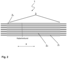
- the 2 1 shows an embodiment in which the section of the cable assembly 1 shown is held together by a single composite element 3, which extends over the entire length of the cable assembly 1 still on the cable drum 4 before the section shown is separated.
- a single composite element 3 which extends over the entire length of the cable assembly 1 still on the cable drum 4 before the section shown is separated.
- a first recess for detaching a cable 2 1 - 2 n from the cable assembly 1 at the location of the branch to be created and another, at a distance towards the end of the section, weleher corresponds to the length required at the junction point for the cable 2 1 - 2 n to be separated from the cable assembly to connect it to a connection point on the property 5 1 - 5 n to be connected, in order to be able to cut through the cable 2 1 - 2 n used to produce the junction here .
- the 3 shows the laying of a cable assembly 1 according to the invention in the ground on a cable route running along five adjacent plots of land 5 1 - 5 n .
- a telecommunications company, through which or on whose behalf the cable route is being laid, would like to take precautionary measures for all properties 5 1 - 5 n along the e.g at a later point in time, provide a cable 2 1 - 2 n , or a fiber optic cable (communication cable), for establishing a communication connection.
- a section of the cables 2 1 - 2 n which have already been joined together by the manufacturer to form a cable assembly 1 and reeled onto a cable drum 4 , is unrolled from the cable drum 4 in question.
- the cable 2 1 - 2 n joined together to form the cable assembly 1 is inserted into the trench previously created along the five plots 5 1 - 5 n in the ground in the example and corresponding to its length a section of that on the cable drum 4 to Cable network 1 made available separated.
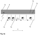
- the figures 4a and 4b show an example of the provision of a fiber optic cable from the cable assembly 1 laid in the cable route for one of the five properties 5 1 - 5 n located on the cable route. If the cables are combined into the cable assembly by a single composite element extending over their entire length, a first recess is made at the level of this property 5 1 - not shown here in detail - in the severed section of the cable assembly 1 over its entire length surrounding composite element 3 introduced.
- a second recess is introduced into the composite element 3 of the cable assembly 1 (likewise not shown in detail).
- the cable 2 2 (optical fiber cable) intended to create the branch to the property 5 1 to be supplied is then severed through this second recess.
- the severed fiber optic cable is finally detached from the cable assembly 1 at the first recess at the level of the property 5 1 for which the fiber optic cable (cable 2 2 ) is to be provided and laid to a connection point provided for this purpose on this property 5 1 .
- the corresponding, previously severed fiber optic cable can be identified, for example, by a color marking on the cable sheath or by a color code (e.g. according to VDE).
Abstract
Die Erfindung betrifft einen Kabelverbund (1) mit mehreren, zu ihrer gemeinsamen Verlegung herstellerseitig zu einem auf einer Kabeltrommel (4) aufgetrommelten Verbund zusammengefassten Kabeln (2<sub>1</sub> - 2<sub>n</sub>). Gemäß der vorgeschlagenen Lösung sind die Kabel (2<sub>1</sub> - 2<sub>n</sub>) zu dem Kabelverbund (1) direkt mittels mindestens eines sie umgebenden Verbundelementes (3, 3', 3") zusammengefasst, und zwar derart, dass jedes der Kabel (2<sub>1</sub> - 2<sub>n</sub>) bezüglich eines jeweiligen, bei der Verlegung von der Kabeltrommel (4) abgerollten Abschnitts des Kabelverbundes (1) innerhalb des mindestens einen die Kabel (2<sub>1</sub> - 2<sub>n</sub>) umgebenden Verbundelementes (3, 3', 3") gegen dieses Verbundelement (3, 3', 3") und gegen die jeweils anderen Kabel (2<sub>1</sub> - 2<sub>n</sub>) des Kabelverbunds (1) in der Längsrichtung (x) beweglich ist. Dadurch ist ein jeweiliges Kabel (2<sub>1</sub> - 2<sub>n</sub>) zur Schaffung eines Kabelabzweigs über eine in dem Kabelverbund (1) mit dem mindestens einen Verbundelement (3, 3', 3") bestehende oder in diesem erzeugte Ausnehmung aus dem Kabelverbund (1) herauslösbar.The invention relates to a cable assembly (1) with a plurality of cables (2<sub>1</sub>-2<sub>n</sub>) that are combined by the manufacturer to form a composite that is reeled onto a cable drum (4) in order to be laid together. According to the proposed solution, the cables (2<sub>1</sub> - 2<sub>n</sub>) are connected to the cable assembly (1) directly by means of at least one composite element (3, 3', 3") summarized in such a way that each of the cables (2<sub>1</sub> - 2<sub>n</sub>) with respect to a respective section of the cable assembly (1st ) within the at least one composite element (3, 3', 3") surrounding the cables (2<sub>1</sub> - 2<sub>n</sub>) against this composite element (3, 3', 3" ) and can be moved in the longitudinal direction (x) against the respective other cables (2<sub>1</sub> - 2<sub>n</sub>) of the cable assembly (1). sub>1</sub> - 2<sub>n</sub>) for creating a cable branch via a recess that exists in the cable assembly (1) with the at least one composite element (3, 3', 3") or is produced in this detachable from the cable assembly (1).
Description
Die Erfindung betrifft einen Kabelverbund, das heißt einen Verbund von mehreren zu ihrer gemeinsamer Verlegung darin zusammengefassten Kabeln. Sie bezieht sich hierbei insbesondere auf einen mehrere Lichtleiterkabel (Lichtwellenleiter - LWL), respektive Glasfaserkabel, wie insbesondere Glasfaserminikabel oder Glasfasermikrokabel, zusammenfassenden Kabelverbund, ohne jedoch auf Kabel dieser Art beschränkt zu sein. Vielmehr können in dem betreffenden, in spezieller Weise gestalteten Kabelverbund im Grunde Kabel beliebiger Art zum Zweck einer gemeinsamen Verlegung zusammengefasst sein.The invention relates to a cable assembly, that is to say an assembly of several cables combined therein for their joint laying. In this context, it refers in particular to a cable assembly that combines several fiber optic cables (optical waveguides - LWL), or glass fiber cables, such as in particular glass fiber minicables or glass fiber microcables, without being limited to cables of this type. Rather, cables of any type can basically be combined in the relevant, specially designed cable assembly for the purpose of laying them together.
Grundsätzlich kann es sich demnach bei den in dem Kabelverbund zusammengefassten Kabeln sowohl um Kabel zur Daten- oder Signalübertragung, also um Kommunikationskabel, als auch um Kabel zur Energie-, respektive Stromübertragung handeln. Mit Blick auf die erstgenannte Kategorie der Kommunikationskabel kann es sich bei den in dem erfindungsgemäß gestalteten Kabelverbund zusammengefassten Kabeln um Kabel mit einem oder mehreren Drähten, respektive Adern, zur elektrischen Datenübertragung oder aber um Glasfaserkabel zur optischen Datenübertragung handeln.In principle, the cables combined in the cable assembly can therefore be both cables for data or signal transmission, ie communication cables, and cables for energy or power transmission. With regard to the first-mentioned category of communication cables, the cables combined in the cable assembly designed according to the invention can be cables with one or more wires or cores for electrical data transmission or fiber optic cables for optical data transmission.
Vor dem Hintergrund des bevorzugten Anwendungsfalls einer gemeinsamen Verlegung von Glasfaserkabeln in Form eines in erfindungsgemäßer Weise gestalteten Kabelverbunds sollen sich die nachfolgenden Ausführungen schwerpunktmäßig - wie gesagt, jedoch ohne Beschränkung - auf diesen Anwendungsfall beziehen.Against the background of the preferred application of laying fiber optic cables together in the form of a cable assembly designed in accordance with the invention, the following explanations are intended to focus on this application—as stated, but without limitation.
Bei der Verlegung von Glasfaserkabeln zur Bereitstellung von Kommunikationsanschlüssen ist es üblich, ein entsprechendes Glasfaserkabel in ein zuvor im Erdreich verlegtes Leerrohr aus Kunststoff einzubringen. In diesem Zusammenhang ist es auch bekannt, mehrere derartige, zur Aufnahme je eines Glasfaserkabels vorgesehene Kunststoffrohre mittels eines die Kunststoffrohre umgebenden gemeinsamen Mantels zu einem Kabel-Rohrverband zusammenzufassen. Ein solcher Rohrverband wird im Erdreich verlegt und kann dann je nach Bedarf mit entsprechenden Glasfaserkabeln bestückt werden. Hinsichtlich des nachträglichen Einbringens der Glasfaserkabel in die Leerrohre, respektive in die Kunststoffrohre, ist es beispielsweise bekannt geworden, die Glasfaserkabel mittels einer Einblasvorrichtung in die Kunststoffrohre einzublasen.When laying fiber optic cables to provide communication connections, it is customary to introduce a corresponding fiber optic cable into an empty plastic conduit previously laid in the ground. In this context, it is also known that several such plastic tubes, each provided for receiving a glass fiber cable, can be connected by means of a plastic tube surrounding the plastic tubes combined into a cable and pipe assembly. Such a bundle of pipes is laid in the ground and can then be equipped with appropriate fiber optic cables as required. With regard to the subsequent introduction of the fiber optic cables into the empty pipes or into the plastic pipes, it has become known, for example, to blow the fiber optic cables into the plastic pipes by means of a blowing device.
In der Praxis gestaltet sich dies so, dass ein eine hinreichend große Zahl von Leerrohren aufweisender, also zunächst noch nicht mit Glasfaserkabeln bestückter Kabel-Rohrverband in eine durch zuvor ausgeführte Erdarbeiten geschaffene Kabeltrasse eingebracht, das heißt in der Erde verlegt wird. An den entlang einer solchen Kabeltrasse gelegenen Grundstücken, welche durch das den Kabel-Rohrverband bereitstellende Unternehmen mit einem Kommunikationsanschluss versorgt werden sollen, werden entsprechende Abzweige geschaffen. Nach der Schaffung dieser Abzweige werden in die Leerrohre des Kabel-Rohrverbandes, so auch in die aus diesem abzweigenden Kunststoffrohre, vor Ort an der Baustelle in entsprechender Anzahl die Glasfaserkabel in die Leerrohre (Kunststoffrohre) eingebracht, zum Beispiel eingeblasen. Häufiger bleibt dabei eine größere Zahl von Leerrohren, respektive Kunststoffrohren, des Kabel-Rohrverbandes zunächst unbestückt. Diese unbestückten, überzähligen Leerrohre können später dazu genutzt werden, im Nachhinein Glasfaserkabel in Kunststoffrohre des Kabel-Rohrverbandes zur Versorgung weiterer, an der Kabeltrasse gelegener Grundstücke mit einem Kommunikationsanschluss des Betreibers des Kabel-Rohrverbandes einzubringen.In practice, this is done in such a way that a cable and pipe assembly that has a sufficiently large number of empty pipes, i.e. that is not yet equipped with fiber optic cables, is introduced into a cable route created by previously carried out excavation work, i.e. laid in the ground. Appropriate branches are created on the properties located along such a cable route, which are to be supplied with a communication connection by the company providing the cable pipe assembly. After the creation of these branches, the fiber optic cables are introduced, for example blown, into the empty pipes of the cable and pipe bundle, as well as into the plastic pipes branching from this, on site at the construction site in the appropriate number. More frequently, a large number of empty conduits, or plastic conduits, of the cable and conduit assembly initially remain unequipped. These unequipped, superfluous empty conduits can later be used to insert fiber optic cables into plastic conduits of the cable-pipe assembly to supply other properties along the cable route with a communication connection of the operator of the cable-pipe assembly.
Nachteilig ist es hierbei, dass das Einbringen der Glasfaserkabel vor Ort an der Baustelle mit einem nicht unerheblichen Montageaufwand verbunden ist. Letzteres gilt vor allen Dingen dann, wenn die Versorgung eines oder einiger Grundstücke durch das den Kabel-Rohrverband bereitstellende Unternehmen erst später, also im Nachhinein, zu einem gegenüber der grundlegenden Erschließung nachgelagerten Ausführungstermin erfolgen soll. Zur nachträglichen Bestückung der Leerrohre ist es dann insbesondere erforderlich, das Erdreich sowie den Kabel-Rohrverband an entsprechenden Übergangsstellen erneut zu öffnen. Für den Vorgang des Einblasens der im Nachhinein einzufügenden Glasfaserkabel ist hierbei das erforderliche Equipment, nämlich beispielsweise eine oder mehrere Einblasvorrichtungen, zur Ausführung der Arbeiten mitzuführen. Das heißt, insbesondere das nachträgliche Bereitstellen von Glasfaserkabeln zur Herstellung eines Kommunikationsanschlusses verursacht einen beträchtlichen logistischen Aufwand und Montageaufwand vor Ort an der Baustelle.The disadvantage here is that the introduction of the fiber optic cable on site at the construction site is associated with a not inconsiderable assembly effort. The latter applies above all if the supply of one or several properties by the company providing the cable and pipe assembly is to take place later, i.e. afterwards, at a later date than the basic development. For the subsequent assembly of the empty pipes, it is then particularly necessary to remove the soil and the cable and pipe assembly open again at appropriate transition points. For the process of blowing in the fiber optic cables to be inserted later, the necessary equipment, namely, for example, one or more blowing devices, must be carried along to carry out the work. This means that in particular the subsequent provision of fiber optic cables for establishing a communication connection causes considerable logistical effort and assembly effort on site at the construction site.
In der
Zur Verlegung der Kommunikationskabel wird der gesamte Kabel-Rohrverband mit den die Kommunikationskabel aufnehmenden Kunststoffrohren entlang einer Kabeltrasse in einen dafür im Erdreich geschaffenen Graben eingebracht. Um ein an der Kabeltrasse gelegenes Grundstück beispielsweise an ein Kommunikationsnetz anzuschließen, also ein Kommunikationskabel des in dem Graben verlegten Kabel-Rohrverbandes mit einem auf dem Grundstück vorgesehenen Anschlusspunkt zu verbinden, werden in den Mantel des Kabel-Rohrverbandes zwei Öffnungen eingebracht. Eine erste Öffnung wird auf Höhe des anzuschließenden Grundstücks erzeugt und eine zweite in einer Entfernung zu der ersten Öffnung, welche mindestens der Entfernung zwischen dieser ersten Öffnung und dem Kabelanschlusspunkt auf dem zu versorgenden Grundstück entspricht. An der zweiten, in dem Mantel des Kabel-Rohrverbandes erzeugten Öffnung werden ein Rohr und das darin befindliche Kommunikationskabel durchtrennt. Das vorgenannte durchtrennte Rohr wird schließlich zusammen mit dem in ihm angeordneten Kommunikationskabel an der ersten in dem Mantel des Kabel-Rohrverbandes geschaffenen Öffnung auf Höhe des zu versorgenden Grundstücks herausgezogen und in Richtung des Anschlusspunktes auf diesem Grundstück verlegt.To lay the communication cable, the entire cable and pipe bundle with the plastic pipes holding the communication cable is placed along a cable route in a ditch created for this purpose in the ground. In order to connect a property located on the cable route to a communication network, i.e. to connect a communication cable from the cable and pipe assembly laid in the trench to a connection point provided on the property, two openings are made in the jacket of the cable and pipe assembly. A first opening is created at the level of the property to be connected and a second at a distance from the first opening which corresponds at least to the distance between this first opening and the cable connection point on the property to be supplied. on the second The opening created in the jacket of the cable-pipe assembly cuts a pipe and the communication cable therein. Finally, the aforesaid severed pipe, together with the communication cable arranged in it, is pulled out at the first opening made in the jacket of the cable-pipe bundle at the level of the property to be supplied and laid in the direction of the connection point on this property.
Trotzdem die zuvor dargestellte Lösung die auf der Baustelle zum Anschluss eines Grundstücks erforderlich werdenden Arbeiten deutlich reduziert, weist auch diese einige Nachteile auf. Ein erster kann darin gesehen werden, dass die beschriebene Lösung, wie auch andere eingangs beschriebene, sich Kunststoffleerrohren bedienende Lösungen, einen nicht unbeträchtlichen Materialaufwand, insbesondere in Gestalt der Kunststoffleerrohre, mit sich bringt. Ein weiterer besteht darin, dass gemäß dem in der
Aufgabe der Erfindung ist es, eine alternative Lösung zur gemeinsamen Verlegung mehrerer Kabel bereitzustellen, welche die vorgenannten Nachteile vermeidet. Die insoweit zu schaffende Lösung soll insbesondere den Montageaufwand vor Ort auf der Baustelle verringern und gleichzeitig einen möglichst geringen Materialaufwand bedingen. Im Einklang mit den beiden vorgenannten Forderungen soll es dabei möglich sein, einzelne Grundstücke entlang einer Trasse, auf welcher die Kabel verlegt werden, flexibel anzuschließen, also einen Anschlusspunkt eines betreffenden Grundstücks mit einem dieser Kabel zu verbinden.The object of the invention is to provide an alternative solution for laying several cables together, which avoids the aforementioned disadvantages. The solution to be created in this respect is intended in particular to reduce the assembly effort on site at the construction site and at the same time require the lowest possible material expenditure. In accordance with the two aforementioned requirements, it should be possible to flexibly connect individual properties along a route on which the cables are laid, i.e. to connect a connection point on a relevant property with one of these cables.
Die Aufgabe wird durch einen Kabelverbund mit den Merkmalen des Patentanspruchs 1 gelöst. Vorteilhafte Ausgestaltungen und Weiterbildungen der Erfindung sind durch die Unteransprüche gegeben.The object is achieved by a cable assembly with the features of
Zur Lösung der Aufgabe wird ein Kabelverbund mit mehreren, zu ihrer gemeinsamen Verlegung herstellerseitig zu einem auf einer Kabeltrommel aufgetrommelten Verbund zusammengefassten Kabeln bereitgestellt. Jedes der Kabel dieses Kabelverbunds besteht aus mindestens einer Übertragungsleitung und einem umgebenden Kabelmantel, wobei der Kabelmantel die von ihm umgebene Übertragungsleitung oder -leitungen gegenüber Umwelteinflüssen, wie sie insbesondere nach einer Verlegung im Erdreich auftreten, sowie vor mechanischen Belastungen schützt. Hinsichtlich der Art der Kabel, respektive der in ihnen enthaltenen mindestens einen Übertragungsleitung, sollen nachfolgend genauere Ausführungen gegeben werden.To solve the problem, a cable assembly is provided with a plurality of cables that are combined by the manufacturer to form an assembly that is reeled onto a cable drum so that they can be laid together. Each of the cables in this cable assembly consists of at least one transmission line and a surrounding cable jacket, the cable jacket protecting the transmission line or lines it surrounds against environmental influences, such as those that occur in particular after laying in the ground, and against mechanical stress. With regard to the type of cables, or the at least one transmission line contained in them, more precise statements are to be made below.
Die mehreren Kabel sind mittels mindestens eines sie umgebenden Verbundelements direkt zu dem Kabelverbund zusammengefasst, und zwar derart, dass jedes der Kabel bezüglich eines jeweiligen, bei der Verlegung von der Kabeltrommel abgerollten Abschnitts des Kabelverbunds innerhalb des mindestens einen, die Kabel umgebenden Verbundelements sowohl gegen dieses Verbundelement als auch gegen die jeweils anderen Kabel des Kabelverbunds in der Längsrichtung beweglich ist. Aufgrund dieser Beweglichkeit der einzelne Kabel in der Längsrichtung, also in der Erstreckungsrichtung und somit vor und zurück, bezogen auf die Verlegerichtung des Kabelverbunds, ist ein jeweiliges Kabel über eine in dem Kabelverbund mit dem mindestens einen Verbundelement bestehende oder in diesem erzeugte Ausnehmung zur Schaffung eines Kabelabzweigs aus dem Kabelverbund herauslösbar.The multiple cables are combined directly into the cable assembly by means of at least one composite element surrounding them, in such a way that each of the cables is connected to a respective section of the cable assembly unrolled from the cable drum during laying within the at least one composite element surrounding the cable, both against this Composite element and against the respective other cable of the cable assembly is movable in the longitudinal direction. Due to this mobility of the individual cables in the longitudinal direction, i.e. in the direction of extension and thus back and forth, in relation to the laying direction of the cable assembly, a respective cable can be connected via a recess that exists in the cable assembly with the at least one composite element or is created in it to create a Cable branch detachable from the cable assembly.
Das heißt, die Kabel sind in dem Kabelverbund weder mechanisch fest noch dauerhaft miteinander verbunden. Die Kabel sind hierbei nicht einzeln durch ein sie umgebendes Rohr (Kunststoffrohr) aufgenommen, sondern mittels des mindestens einen Verbundelements direkt, das heißt unmittelbar, zu dem Kabelverbund zusammengefügt. Das mindestens eine Verbundelement - genauere Ausführungen zu dessen Beschaffenheit erfolgen später - dient lediglich dem temporären Zusammenhalt der Kabel und damit dazu, mehrere Kabel entlang einer Kabeltrasse in einem dafür geschaffenen Graben im Erdreich gleichzeitig zu verlegen. Die Kabel werden hierzu, wie bereits ausgeführt, bereits herstellerseitig im Verbund miteinander aufgetrommelt. Das mindestens eine, die Kabel des Kabelverbunds umgebende Verbundelement hat also weder für die auf der Kabeltrommel aufgerollten Kabel des Kabelverbunds noch für einen von dieser abgerollten und im Erdreich verlegten Abschnitt des Kabelverbunds eine Schutzfunktion. Es dient vielmehr lediglich dazu, eine effiziente Verlegung der in dem Verbund zusammengefassten Kabel zu ermöglichen. In diesem Zusammenhang ist anzumerken, dass bei der hier vorgeschlagenen technischen Lösung bereits der Verzicht auf entsprechende, die einzelnen Kabel aufnehmende Kunststoffrohre zu einer signifikanten Materialeinsparung führt.This means that the cables in the cable assembly are neither mechanically fixed nor permanently connected to one another. In this case, the cables are not received individually by a tube (plastic tube) surrounding them, but by means of the at least one composite element directly, ie directly, to the cable assembly put together. The at least one composite element - more detailed information on its nature will be given later - only serves to temporarily hold the cables together and thus to lay several cables simultaneously along a cable route in a ditch in the ground created for this purpose. For this purpose, as already explained, the cables are already reeled together by the manufacturer. The at least one composite element surrounding the cables of the cable assembly therefore has no protective function either for the cables of the cable assembly rolled up on the cable drum or for a section of the cable assembly unrolled from the cable drum and laid in the ground. Rather, it only serves to enable efficient laying of the cables combined in the assembly. In this context, it should be noted that in the technical solution proposed here, the mere omission of corresponding plastic tubes accommodating the individual cables leads to a significant saving in material.
Grundsätzlich ist es hierbei möglich, zu einem derartigen Kabelverbund, in welchem die Kabel - wie gesagt - im Grunde nur temporär zusammengefasst sind, Kabel unterschiedlichster Art und folglich für verschiedenste Verwendungszwecke zusammenzuführen. Unter Außerbetrachtlassung eventueller unerwünschter elektromagnetischer Wechselwirkungen zwischen mehreren, in Form eines solchen Kabelverbunds gleichzeitig in einem Kabelgraben verlegten Kabeln, wäre es hierbei sogar denkbar, Stromversorgungskabel und Kommunikationskabel gemeinsam in einem derartigen Kabelverbund zusammenzufassen, wobei dies jedoch im Hinblick auf die schon angesprochenen möglichen Wechselwirkungen und aus sonstigen praktischen Erwägungen heraus regelmäßig eher nicht der Fall sein wird.In principle, it is possible here to combine cables of the most varied types and consequently for the most varied of uses to form such a cable assembly, in which the cables—as mentioned—are basically only temporarily combined. Leaving aside possible undesired electromagnetic interactions between several cables laid simultaneously in a cable trench in the form of such a cable assembly, it would even be conceivable to combine power supply cables and communication cables together in such a cable assembly, although this is with regard to the possible interactions already mentioned and from other practical considerations will not be the case as a rule.
Im Hinblick auf bevorzugte Einsatzszenarien besteht eine praxisrelevante Ausbildungsform eines solchen Kabelverbunds vorzugsweise aus mehreren Kommunikationskabeln, das heißt ausschließlich aus darin zusammengefassten Kommunikationskabeln. Besonders bevorzugt handelt es sich bei diesen Kommunikationskabeln um Lichtleiterkabel (synonym auch Lichtleitkabel), wie insbesondere um Glasfaserminikabel oder um Glasfasermikrokabel. Die betreffenden, der Datenübertragung mittels optischer Übertragungsverfahren dienenden Kommunikationskabel, also Lichtleiterkabel, bestehen hierbei typischerweise jeweils aus mehreren, von einem gemeinsamen Kabelmantel umgebenen Lichtleitfasern, respektive Glasfasern. Gemäß dem hier zugrunde gelegten Verständnis weisen dabei Glasfaserminikabel einen Durchmesser von ≤ 6,50 mm (2,70 mm - 6,50 mm) auf, wohingegen Glasfasermikrokabel sogar Durchmesser von ≤ 2,60 mm aufweisen.With regard to preferred application scenarios, a practice-relevant embodiment of such a cable assembly preferably consists of a plurality of communication cables, that is to say exclusively of communication cables combined therein. These communication cables are particularly preferably fiber optic cables (synonymously also fiber optic cables), such as in particular fiber optic minicable or fiber optic microcable. The relevant communication cables used for data transmission by means of optical transmission methods, ie fiber optic cables, typically consist of a plurality of optical fibers or glass fibers surrounded by a common cable jacket. According to the understanding on which this is based, glass fiber minicables have a diameter of ≦6.50 mm (2.70 mm - 6.50 mm), whereas glass fiber microcables even have a diameter of ≦2.60 mm.
Hierbei ist es möglich, dass die jeweils für sich nicht von einem Kunststoffrohr oder dergleichen umgebenen Kabel mittels eines alle Kabel gemeinsam über die gesamte Länge des Kabelverbunds umgebenden, schlauchartigen Verbundelements zu dem Kabelverbund zusammengefasst sind. Bei dieser Ausbildungsform ist es dann erforderlich, die eingangs angesprochene Ausnehmung zur Schaffung eines Kabelabzweigs mittels eines aus dem Kabelverbund herausgelösten Kabels in dem Verbundelement nach der Verlegung des Kabelverbunds zu schaffen, also gewissermaßen auf der Höhe eines anzuschließenden Grundstücks ein Fenster in das Verbundelement einzubringen. Selbstverständlich muss darüber hinaus auch hier in einem Abstand, welcher der erforderlichen Länge des zu schaffenden Abzweigs entspricht, eine weitere Ausnehmung in das den gesamten verlegten Abschnitt des Kabelverbunds umgebende Verbundelement eingebracht werden, um das für den Abzweig aus dem Kabelverbund herauszulösende Kabel über diese zweite Ausnehmung durchtrennen zu können.It is possible here for the cables not individually surrounded by a plastic tube or the like to be combined into the cable assembly by means of a hose-like composite element that encloses all the cables together over the entire length of the cable assembly. In this embodiment, it is then necessary to create the above-mentioned recess for creating a cable junction by means of a cable that has been detached from the cable assembly in the composite element after the cable assembly has been laid, i.e. to introduce a window in the composite element at the level of a property to be connected. Of course, a further recess must also be made in the composite element surrounding the entire laid section of the cable assembly at a distance which corresponds to the required length of the branch to be created, in order to be able to release the cable from the cable assembly for the branch via this second recess to be able to cut.
Bei einer demgegenüber bevorzugten Ausbildungsform des Kabelverbunds ist es hingegen nicht erforderlich, eine oder mehrere Öffnungen, respektive Ausnehmungen, in ein Verbundelement einzubringen, um das Herauslösen eines - wie gesagt, selbst nicht von einem Rohr umgebenen - Kabels aus dem Kabelverbund zur Schaffung eines Abzweigs zu ermöglichen. Bei dieser Ausbildungsform werden die Kabel des Verbunds durch mehrere streifenförmige, entlang der Erstreckungsrichtung der Kabel (Längsrichtung des Kabelverbunds) zueinander beabstandete Verbundelemente, das heißt durch mehrere sich jeweils bezogen auf die Umfangsrichtung der Kabel in Form eines Streifens erstreckende Verbundelemente, zusammengehalten. Über die gesamte Länge des Kabelverbunds sind hierbei mehrere derartiger streifenförmiger Verbundelemente, vorzugsweise in einem äquidistanten Abstand zueinander angeordnet.In contrast, in a preferred embodiment of the cable assembly, it is not necessary to introduce one or more openings or recesses in a composite element in order to prevent the detachment of a cable - which, as I said, is not itself surrounded by a pipe - from the cable assembly to create a branch make possible. In this embodiment, the cables of the assembly are connected by a plurality of strip-shaped composite elements that are spaced apart from one another along the direction in which the cables extend (longitudinal direction of the cable assembly), ie by a plurality of the circumferential direction of the cables in the form of a strip extending composite elements, held together. In this case, a plurality of such strip-shaped composite elements are arranged over the entire length of the cable assembly, preferably at an equidistant distance from one another.
Bei einem aus einer Mehrzahl von Lichtleiterkabeln gebildeten Kabelverbund weisen die streifenförmigen Verbundelemente untereinander beispielsweise einen Abstand zwischen 30 und 60 cm auf und besitzen demgegenüber jeweils eine Streifenbreite von zirka 5 bis 10 cm. Die zwischen den Verbundelementen bestehenden Abstände stellen hierbei bereits von Anfang an bestehende Ausnehmungen dar, über welche die zum Verbund gehörenden Kabel frei zugänglich sind und somit einzelne Kabel zur Schaffung eines jeweiligen Abzweigs an entsprechender Stelle durchtrennt sowie (gegebenenfalls einschließlich des abgetrennten Endes) aus dem Verbund herausgezogen, also herausgelöst werden können.In a cable assembly formed from a plurality of fiber optic cables, the strip-shaped composite elements are, for example, at a distance of between 30 and 60 cm from one another and, in contrast, each have a strip width of approximately 5 to 10 cm. The distances existing between the composite elements represent recesses that exist from the outset, via which the cables belonging to the composite are freely accessible and thus individual cables are severed at the appropriate point to create a respective branch and (possibly including the severed end) from the composite pulled out, so can be detached.
In vorteilhafter Weise reduzieren sich hierdurch einerseits der Materialaufwand, nämlich die für die nunmehr mehreren Verbundelemente benötigte Materialmenge, sowie der Arbeitsaufwand auf der Baustelle. Letzteres resultiert ersichtlich daraus, dass es bei dieser Ausbildungsform nicht mehr nötig ist, auf der Baustelle im Zuge der Verlegung des Kabelverbunds und der nachfolgenden Schaffung von Abzweigen aus diesem Kabelverbund entsprechende Ausnehmungen mittels dafür erforderlicher Werkzeuge in das beziehungsweise die Verbundelemente einzubringen.This advantageously reduces the cost of materials, namely the amount of material now required for the multiple composite elements, as well as the amount of work on the construction site. The latter obviously results from the fact that with this form of embodiment it is no longer necessary to introduce corresponding recesses into the composite element(s) using the tools required for this purpose on site during the course of laying the cable assembly and the subsequent creation of branches from this cable assembly.
Ungeachtet dessen, ob der Kabelverbund mittels eines sich über dessen gesamte Länge erstreckenden Verbundelements oder mittels mehrerer voneinander beabstandeter Verbundelemente realisiert wird, wird als Material für das oder die Verbundelemente ein Kunststoff, wie beispielsweise Polyethylen vorgeschlagen. Durch die Wahl eines auf das Material des Kabelmantels der jeweiligen zu dem Kabelverbund zusammengefügten Kabel abgestimmten Materials für das oder die Verbundelemente ist, dem Grundgedanken der vorgeschlagenen Lösung folgend, in jedem Falle sicherzustellen, dass innerhalb des oder der Verbundelemente die erforderliche Beweglichkeit der Kabel gegenüber dem Verbundelement und untereinander gegeben ist.Irrespective of whether the cable assembly is realized by means of a composite element extending over its entire length or by means of several composite elements spaced apart from one another, a plastic such as polyethylene is proposed as the material for the composite element or elements. By choosing a material for the composite element or composite elements that is tailored to the material of the cable sheath of the respective cable assembled to form the cable assembly, following the basic idea of the proposed solution, ensure in any case that within the composite element or elements, the required mobility of the cables relative to the composite element and among one another is given.
Eine weitere, alternative Ausbildungsform des Kabelverbunds ist dadurch gegeben, dass die zu ihm zusammengefügten Kabel in dem Verbund durch eine insoweit ebenfalls ein Verbundelement ausbildende Verseilung gehalten werden. Auch bei dieser Ausbildungsform, bei welcher beispielsweise ein Faden in einem spiralförmigen Verlauf um die Kabel herumgeschlungen wird, wird es regelmäßig nicht nötig sein, zu Schaffung eines Abzweigs auf der Baustelle eine Ausnehmung in das solchermaßen ausgebildete Verbundelement einzubringen, das heißt den entsprechenden Faden zu zertrennen.A further, alternative embodiment of the cable assembly is given by the fact that the cables joined together to form it are held in the assembly by a stranding that likewise forms a composite element. Even with this form of construction, in which, for example, a thread is looped around the cable in a spiral course, it will generally not be necessary to make a recess in the composite element designed in this way to create a branch on the construction site, i.e. to cut the corresponding thread .
Nachfolgend sollen anhand von Zeichnungen Ausführungsbeispiele für die Erfindung gegeben und deren Verwendung im praktischen Einsatz erläutert werden. Die Zeichnungen zeigen im Einzelnen:
- Fig. 1:
- einen Abschnitt eines mittels mehrerer Verbundelemente realisierten Kabelverbunds,
- Fig. 2:
- einen Abschnitt eines mittels sich über die gesamte Abschnittslänge erstreckenden Verbundelements realisierten Kabelverbunds,
- Fig. 3:
- die Verlegung eines Kabelverbunds gemäß der vorgeschlagenen Lösung in einer Kabeltrasse entlang von mehreren Grundstücken,
- Fig. 4a und 4b:
- die Bereitstellung eines Glasfaserkabels für eines der Grundstücke zur Herstellung eines Kommunikationsanschlusses,
- Fig. 5:
- die Gegebenheiten nach der Bereitstellung eines Glasfaserkabels für ein weiteres Grundstück bei der Bebauungssituation gemäß
den Figuren 3 und4 , - Fig. 6:
- die vorsorgliche Bereitstellung eines Glasfaserkabels für ein weiteres bebautes Grundstück und ein noch nicht bebautes Grundstück gemäß der Bebauungssituation nach
den Figuren 3 bis 5 .
- Figure 1:
- a section of a cable assembly realized by means of several composite elements,
- Figure 2:
- a section of a cable assembly realized by means of a composite element extending over the entire length of the section,
- Figure 3:
- the laying of a cable assembly according to the proposed solution in a cable route along several properties,
- Figures 4a and 4b:
- the provision of a fiber optic cable to one of the properties to establish a communications link,
- Figure 5:
- the circumstances after the provision of a fiber optic cable for another property in the development situation according to the
Figures 3 and4 , - Figure 6:
- the precautionary provision of a fiber optic cable for another developed property and a not yet developed property according to the development situation according to the
Figures 3 to 5 .
In der
Die zwischen den Verbundelementen 3, 3', 3" bestehenden Abstände, respektive Lücken, bilden hierbei Ausnehmungen auf, über welche ein zuvor auf entsprechender Länge durchtrenntes Kabel 21 - 2n aus dem Kabelverbund 1 herausgelöst, das heißt herausgezogen, sowie unter Schaffung eines Abzweigs in Richtung eines Anschlusspunktes auf einem Grundstück 51 - 5n entlang der Kabeltrasse verlegt werden kann.The distances or gaps between the
Die
In den nachfolgenden Figuren soll der Vorgang der Verlegung des Kabelverbunds 1. Die
Die
Durch diese zweite Ausnehmung hindurch wird dann das zur Schaffung des Abzweigs zum dem zu versorgenden Grundstück 51 vorgesehene Kabel 22 (Glasfaserkabel) durchtrennt. Das durchtrennte Glasfaserkabel wird schließlich an der ersten Ausnehmung auf Höhe des Grundstücks 51, für welches das Glasfaserkabel (Kabel 22) bereitzustellen ist, aus dem Kabelverbund 1 herausgelöst sowie bis zu einem auf diesem Grundstück 51 dafür vorgesehenen Anschlusspunkt verlegt. Das entsprechende, zuvor durchgetrennte Glasfaserkabel kann zum Beispiel an einer Farbmarkierung auf dem Kabelmantel beziehungsweise an einem Farbcode (beispielsweise nach VDE) erkannt werden. Das Erzeugen der vorgenannten Öffnungen (erste Ausnehmung und zweite Ausnehmung) auf der Baustelle, zum Durchtrennen und Herausziehen eines Kabels 21 - 2n, aus dem Rohrverbund 1, kann - wie bereits ausgeführt - entfallen, sofern die Kabel 21 - 2n, mittels mehrerer streifenförmiger. voneinander beabstandeter Verbundelemente 3, 3', 3" zu dem Kabelverbund 1 zusammengefasst sind.The cable 2 2 (optical fiber cable) intended to create the branch to the property 5 1 to be supplied is then severed through this second recess. The severed fiber optic cable is finally detached from the
Wie in der
Claims (9)
Applications Claiming Priority (1)
| Application Number | Priority Date | Filing Date | Title |
|---|---|---|---|
| DE102021128334.5A DE102021128334B4 (en) | 2021-10-29 | 2021-10-29 | Cable assembly |
Publications (1)
| Publication Number | Publication Date |
|---|---|
| EP4174547A1 true EP4174547A1 (en) | 2023-05-03 |
Family
ID=83996547
Family Applications (1)
| Application Number | Title | Priority Date | Filing Date |
|---|---|---|---|
| EP22203549.5A Pending EP4174547A1 (en) | 2021-10-29 | 2022-10-25 | Cable composite |
Country Status (2)
| Country | Link |
|---|---|
| EP (1) | EP4174547A1 (en) |
| DE (1) | DE102021128334B4 (en) |
Citations (8)
| Publication number | Priority date | Publication date | Assignee | Title |
|---|---|---|---|---|
| FR2528220A1 (en) * | 1982-06-08 | 1983-12-09 | Nonclerq Bernard | Fibre-optic telecommunications cable - has conductors loosely held in metal tubes with friction reducing plastic balls between each conductor and tube |
| US5625737A (en) * | 1995-12-11 | 1997-04-29 | Lucent Technologies Inc. | Optical fiber holder and method using same |
| EP1309054A1 (en) * | 2000-08-07 | 2003-05-07 | Ashimori Industry Co., Ltd. | Method and structure for laying communication cable in underground line, and members used for laying |
| JP2005204374A (en) * | 2004-01-14 | 2005-07-28 | Sanwa Denki Kogyo Co Ltd | Cable holding device |
| EP2080944A1 (en) * | 2008-01-15 | 2009-07-22 | Emtelle UK Limited | Tube assembly for receiving optical fibre cables and retaining device for forming tube assemblies |
| US20100158455A1 (en) * | 2007-05-31 | 2010-06-24 | Draka Comteq B.V. | Cable, And A Use And Method For Constructing A Cable Network |
| JP2014153521A (en) * | 2013-02-08 | 2014-08-25 | Sumitomo Electric Ind Ltd | Optical cable |
| DE102019117612A1 (en) | 2019-06-28 | 2020-12-31 | Deutsche Telekom Ag | Cable duct bundle, method of manufacture and laying |
Family Cites Families (2)
| Publication number | Priority date | Publication date | Assignee | Title |
|---|---|---|---|---|
| EA019479B1 (en) | 2007-05-04 | 2014-04-30 | Тераспан Нетворкс Инк. | Fibre optic network installation |
| DE102007046798A1 (en) | 2007-09-29 | 2009-04-02 | Petruch, Dieter, Dipl.-Ing. | Preconfined electric cable laying method for building, involves marking cables by marker before moving into pipe, and rolling pipe and cables as goods by bobbin, where pipe preconfined with cables is laid in walls, floors and/or ceiling |
-
2021
- 2021-10-29 DE DE102021128334.5A patent/DE102021128334B4/en active Active
-
2022
- 2022-10-25 EP EP22203549.5A patent/EP4174547A1/en active Pending
Patent Citations (8)
| Publication number | Priority date | Publication date | Assignee | Title |
|---|---|---|---|---|
| FR2528220A1 (en) * | 1982-06-08 | 1983-12-09 | Nonclerq Bernard | Fibre-optic telecommunications cable - has conductors loosely held in metal tubes with friction reducing plastic balls between each conductor and tube |
| US5625737A (en) * | 1995-12-11 | 1997-04-29 | Lucent Technologies Inc. | Optical fiber holder and method using same |
| EP1309054A1 (en) * | 2000-08-07 | 2003-05-07 | Ashimori Industry Co., Ltd. | Method and structure for laying communication cable in underground line, and members used for laying |
| JP2005204374A (en) * | 2004-01-14 | 2005-07-28 | Sanwa Denki Kogyo Co Ltd | Cable holding device |
| US20100158455A1 (en) * | 2007-05-31 | 2010-06-24 | Draka Comteq B.V. | Cable, And A Use And Method For Constructing A Cable Network |
| EP2080944A1 (en) * | 2008-01-15 | 2009-07-22 | Emtelle UK Limited | Tube assembly for receiving optical fibre cables and retaining device for forming tube assemblies |
| JP2014153521A (en) * | 2013-02-08 | 2014-08-25 | Sumitomo Electric Ind Ltd | Optical cable |
| DE102019117612A1 (en) | 2019-06-28 | 2020-12-31 | Deutsche Telekom Ag | Cable duct bundle, method of manufacture and laying |
Also Published As
| Publication number | Publication date |
|---|---|
| DE102021128334A1 (en) | 2023-05-04 |
| DE102021128334B4 (en) | 2023-12-14 |
Similar Documents
| Publication | Publication Date | Title |
|---|---|---|
| DE69919358T2 (en) | POETRY | |
| EP0953162B1 (en) | Fibre-optic cable network | |
| DE2631538A1 (en) | OVERLAND LINE AND ITS LAYING | |
| EP0990932B1 (en) | Informationcablenetwork in a duct or tube system primarily used for other purposes | |
| DE102019117612B4 (en) | Cable duct bundle, method of manufacture and laying | |
| DE3525723A1 (en) | UNDERWATER LINE FOR MESSAGE TRANSMISSION USING OPTICAL FIBERS | |
| DE3031833C2 (en) | String-shaped connecting element made of plastic for cables, etc. | |
| EP3275061A1 (en) | Method and device for producing a pipe assembly of cable pipes | |
| DE4227464A1 (en) | EMPTY TUBE WITH DETACHABLE CABLE ASSEMBLY | |
| DE102021128334B4 (en) | Cable assembly | |
| DE3106661C2 (en) | Arrangement for locating a metal-free cable | |
| DE8213407U1 (en) | Cable routing unit | |
| EP0509299B1 (en) | Optical cable | |
| EP0547323B1 (en) | Device for connecting optical waveguides at a branching point and method of connecting optical waveguides at a branching point | |
| EP3958415B1 (en) | Method and device for producing a tubular bundle from cable tubes | |
| EP1705505A1 (en) | Device for structured storage and handling of fibre optics conducted in micro cables | |
| DE4314520C1 (en) | Cuff set for optical fibre communications cable | |
| DE10141720A1 (en) | Optical cable comprises at least one or more light conductors which is/are surrounded by a plastic tube which for better grippability is provided with at least one string-like element | |
| DE19750932C1 (en) | Fiber optic termination module and installation of data and telecommunications technology | |
| DE102020111157A1 (en) | Method and device for the production of a pipe assembly from cable ducts | |
| WO2003060585A1 (en) | Method for laying a fibre optic cable in a gas conduit and a cable laying device | |
| AT4202U1 (en) | FIBERGLASS CABLE | |
| EP1095303A1 (en) | Protection of telecommunication glass fibers with air-space paper-insulated core | |
| EP3978977A1 (en) | Holding device | |
| DE3537682A1 (en) | Optical fibre cable branch and method for producing it |
Legal Events
| Date | Code | Title | Description |
|---|---|---|---|
| PUAI | Public reference made under article 153(3) epc to a published international application that has entered the european phase |
Free format text: ORIGINAL CODE: 0009012 |
|
| STAA | Information on the status of an ep patent application or granted ep patent |
Free format text: STATUS: THE APPLICATION HAS BEEN PUBLISHED |
|
| AK | Designated contracting states |
Kind code of ref document: A1 Designated state(s): AL AT BE BG CH CY CZ DE DK EE ES FI FR GB GR HR HU IE IS IT LI LT LU LV MC ME MK MT NL NO PL PT RO RS SE SI SK SM TR |
|
| STAA | Information on the status of an ep patent application or granted ep patent |
Free format text: STATUS: REQUEST FOR EXAMINATION WAS MADE |
|
| 17P | Request for examination filed |
Effective date: 20231030 |
|
| RBV | Designated contracting states (corrected) |
Designated state(s): AL AT BE BG CH CY CZ DE DK EE ES FI FR GB GR HR HU IE IS IT LI LT LU LV MC ME MK MT NL NO PL PT RO RS SE SI SK SM TR |