EP4174530A1 - Audiowiedergabe eines elektromagnetischen metalldetektionssignals - Google Patents
Audiowiedergabe eines elektromagnetischen metalldetektionssignals Download PDFInfo
- Publication number
- EP4174530A1 EP4174530A1 EP22204318.4A EP22204318A EP4174530A1 EP 4174530 A1 EP4174530 A1 EP 4174530A1 EP 22204318 A EP22204318 A EP 22204318A EP 4174530 A1 EP4174530 A1 EP 4174530A1
- Authority
- EP
- European Patent Office
- Prior art keywords
- signal
- detection signal
- detection
- dynamic range
- audio
- Prior art date
- Legal status (The legal status is an assumption and is not a legal conclusion. Google has not performed a legal analysis and makes no representation as to the accuracy of the status listed.)
- Granted
Links
Images





Classifications
-
- H—ELECTRICITY
- H04—ELECTRIC COMMUNICATION TECHNIQUE
- H04R—LOUDSPEAKERS, MICROPHONES, GRAMOPHONE PICK-UPS OR LIKE ACOUSTIC ELECTROMECHANICAL TRANSDUCERS; ELECTRIC HEARING AIDS; PUBLIC ADDRESS SYSTEMS
- H04R3/00—Circuits for transducers
-
- G—PHYSICS
- G01—MEASURING; TESTING
- G01V—GEOPHYSICS; GRAVITATIONAL MEASUREMENTS; DETECTING MASSES OR OBJECTS; TAGS
- G01V3/00—Electric or magnetic prospecting or detecting; Measuring magnetic field characteristics of the earth, e.g. declination, deviation
- G01V3/15—Electric or magnetic prospecting or detecting; Measuring magnetic field characteristics of the earth, e.g. declination, deviation specially adapted for use during transport, e.g. by a person, vehicle or boat
- G01V3/165—Electric or magnetic prospecting or detecting; Measuring magnetic field characteristics of the earth, e.g. declination, deviation specially adapted for use during transport, e.g. by a person, vehicle or boat operating with magnetic or electric fields produced or modified by the object or by the detecting device
-
- G—PHYSICS
- G01—MEASURING; TESTING
- G01V—GEOPHYSICS; GRAVITATIONAL MEASUREMENTS; DETECTING MASSES OR OBJECTS; TAGS
- G01V3/00—Electric or magnetic prospecting or detecting; Measuring magnetic field characteristics of the earth, e.g. declination, deviation
- G01V3/08—Electric or magnetic prospecting or detecting; Measuring magnetic field characteristics of the earth, e.g. declination, deviation operating with magnetic or electric fields produced or modified by objects or geological structures or by detecting devices
- G01V3/10—Electric or magnetic prospecting or detecting; Measuring magnetic field characteristics of the earth, e.g. declination, deviation operating with magnetic or electric fields produced or modified by objects or geological structures or by detecting devices using induction coils
- G01V3/101—Electric or magnetic prospecting or detecting; Measuring magnetic field characteristics of the earth, e.g. declination, deviation operating with magnetic or electric fields produced or modified by objects or geological structures or by detecting devices using induction coils by measuring the impedance of the search coil; by measuring features of a resonant circuit comprising the search coil
-
- G—PHYSICS
- G08—SIGNALLING
- G08B—SIGNALLING SYSTEMS, e.g. PERSONAL CALLING SYSTEMS; ORDER TELEGRAPHS; ALARM SYSTEMS
- G08B3/00—Audible signalling systems, e.g. audible personal calling systems
- G08B3/10—Audible signalling systems, e.g. audible personal calling systems using electric transmission; using electromagnetic transmission
-
- H—ELECTRICITY
- H03—ELECTRONIC CIRCUITRY
- H03G—CONTROL OF AMPLIFICATION
- H03G3/00—Gain control in amplifiers or frequency changers
- H03G3/20—Automatic control
- H03G3/30—Automatic control in amplifiers having semiconductor devices
- H03G3/3052—Automatic control in amplifiers having semiconductor devices in bandpass amplifiers (H.F. or I.F.) or in frequency-changers used in a (super)heterodyne receiver
-
- G—PHYSICS
- G01—MEASURING; TESTING
- G01V—GEOPHYSICS; GRAVITATIONAL MEASUREMENTS; DETECTING MASSES OR OBJECTS; TAGS
- G01V3/00—Electric or magnetic prospecting or detecting; Measuring magnetic field characteristics of the earth, e.g. declination, deviation
- G01V3/08—Electric or magnetic prospecting or detecting; Measuring magnetic field characteristics of the earth, e.g. declination, deviation operating with magnetic or electric fields produced or modified by objects or geological structures or by detecting devices
- G01V3/10—Electric or magnetic prospecting or detecting; Measuring magnetic field characteristics of the earth, e.g. declination, deviation operating with magnetic or electric fields produced or modified by objects or geological structures or by detecting devices using induction coils
- G01V3/104—Electric or magnetic prospecting or detecting; Measuring magnetic field characteristics of the earth, e.g. declination, deviation operating with magnetic or electric fields produced or modified by objects or geological structures or by detecting devices using induction coils using several coupled or uncoupled coils
-
- H—ELECTRICITY
- H04—ELECTRIC COMMUNICATION TECHNIQUE
- H04R—LOUDSPEAKERS, MICROPHONES, GRAMOPHONE PICK-UPS OR LIKE ACOUSTIC ELECTROMECHANICAL TRANSDUCERS; ELECTRIC HEARING AIDS; PUBLIC ADDRESS SYSTEMS
- H04R2430/00—Signal processing covered by H04R, not provided for in its groups
Definitions
- the present invention relates generally to the field of metal detection by means of portable electromagnetic detectors, and more particularly to the audio reproduction of an electromagnetic metal detection signal.
- Such metal detectors are used mainly for leisure, for example for the search and discrimination of metal objects buried in the ground such as coins, jewellery, treasures or gold nuggets, but also by professionals, for example for demining, ballistics research, or even the search for pipes in the building industry or polluting metal particles in the food sector. These application examples are not limiting. Modern handheld metal detectors allow the user to not only spot but also identify a target buried in the ground.
- metal detectors comprise an electromagnetic detection head, or more simply detection head or detection disk, which constitutes the active part of the detector, and which is mounted at the end of a handling rod.
- This detection head adopts the shape of a disc because it comprises one or more inductive coils which make it possible to generate an incident electromagnetic field, and to receive a resulting magnetic field modified by the immediate environment.
- the detection head can also embed control electronics, suitable for producing an alternating electromagnetic signal at the origin of the incident electromagnetic field, and for processing a received electromagnetic detection signal corresponding to the resulting magnetic field. This processing makes it possible to detect and discriminate any metal objects exposed to the incident electromagnetic field.
- the head of detection embeds only part of the electronics for exploiting the received electromagnetic detection signal, for example a preamplifier, the rest of this electronics being remote in a control box to which the detection head is connected.
- an alternating magnetic field is emitted " continuously " and the detection is based on the variations of amplitude and phase between the frequency components of the transmitted signal and those of the received signal.
- the CW detectors use the amplitude and phase measurement of the various components of the alternating electromagnetic signal emitted by at least one transmitter coil supplied with an electric voltage, and the components of the electromagnetic signal received by one or more receiver coils arranged close to the transmitter coil.
- the frequency of the signal emitted by the transmitter coil is generally less than 100 kHz.
- the transmitting coil and the receiving coil(s) are only one and the same coil.
- the implementation of the principle of the induction balance makes it possible to measure by induction very small changes in the properties of the medium. This is achieved by arranging the transmit and receive coils so that the mutual inductance of the receive coil(s) and the transmit coil(s) is as low as possible. This makes it possible to minimize the electromagnetic field measured in the absence of a target. The coupling of the two coils is then such, in fact, that the signal received by the receiver coil is substantially zero when no metallic element is placed in the field of the transmitter coil. This makes it possible to optimize the dynamics of the measurement signal by measuring only the variations of the resulting electromagnetic field.
- the most common configuration is that of the "double D" head, but other configurations are possible, for example with concentric coils, or by placing the coils at 90° to each other, or even with auxiliary coils used to generate a compensation field, or even with other geometries.
- the received signal can be seen as the sum of different exponential decays which are representative of the environment in which one operates.
- detectors which work simultaneously in the two modes, namely the CW mode and the PI mode.
- the user surveys a determined area to be explored by sweeping the terrain with the portable detector, via the handling rod, which saves him from having to bend down or bend over. Specifically, he stands upright and moves the searchcoil parallel to the ground using the cane, sweeping the searchcoil from left to right, then right to left, and so on.
- the emission coil produces a magnetic field which, at the level of a possible metallic target which is fixed, varies over time because the detection head is thus set in motion. This magnetic field generates eddy currents in the metallic target that one seeks to detect.
- the electromagnetic signal received also called target detection signal or more simply detection signal or just signal in what follows, has an amplitude which varies when the detection head moves above the target, in proportion to the magnetic fields. produced by the circulation of eddy currents generated in the target, and received by the detection head.
- the electromagnetic signal received is then amplified and processed by the control electronics, so as to isolate the signal associated with the desired target and to separate it from parasitic signals (industrial parasites, weather, variation associated with the ground, the earth's magnetic field, parasitic targets, etc.).
- the effective detection range of the metal detector depends on the type of target and the technology used by the detector manufacturer. It is limited by the signal-to-noise ratio (" Signal-to-Noise Ratio " or SNR, in English) which depends on the physical characteristics of the control electronics of the metal detector, the signal processing implemented and of the various spurious signals to which the detection disc is subjected. The majority of detectors therefore have a threshold setting below which the detection signal is not taken into account, either because it is located in the noise, or because one deliberately wishes to ignore targets that are too small. size.
- discrimination information which enriches the main information relating to the level of intensity of the target detection signal, with data relating to the characteristics of the target (for its ferrous or non-ferrous nature) and/or its environment (for example the characteristics of the soil such as conductivity).
- the relevance of this discrimination information is highly dependent on the signal-to-noise ratio of the detector.
- the signal amplitude and discrimination information can be returned to the user by various sensory channels, in particular auditory or visual. Audio playback is preferred, and the most widely used, as it allows the user to stay focused on scanning the ground with the search coil.
- the sensing signal has an amplitude that varies as the sensing head moves over the target in proportion to the magnetic fields produced by the flow of eddy currents generated in the target and received by the sensing head.
- the analysis of this signal makes it possible to detect targets, providing the user with indications to help him in the detection and identification of metallic targets.
- These indications are extracted from the electromagnetic detection signal by signal processing techniques known per se. They are generally presented, i.e. returned to the user in sound form using an electro-acoustic transducer such as, for example, an audio headset.
- an audio signal is generated from the electromagnetic detection signal and is delivered to the user's audio headset, for example a wireless headset.
- Audio playback methods that can be used consist in generating a sound whose amplitude and/or frequency are modulated by the amplitude of the detected signal.
- the highest amplitude audio signal may indicate the position of the target closest to the disc of detection. It is also possible to use such an amplitude modulation of the signal, the frequency of which is also determined by the discrimination information. Also, the amplitude and the frequency of the audio signal can be modulated simultaneously as a function of the detection signal. Generally, the loudest and highest pitched audio signal indicates the position of the target closest to the searchcoil. It is also possible to carry out an amplitude and/or frequency modulation by reserving certain frequency ranges for certain types of target, and other frequency ranges for other types of target, respectively. Thus, for example ferrous targets can be signaled by much lower frequencies than non-ferrous targets.
- the amplitude of the audio signal by varying the duty cycle of a rectangular signal attacking the electroacoustic transducer. For example, the duty cycle thereof goes from 0% for a zero detection signal to 50% (ie, at a square signal) for the strongest detection signal.
- this has the advantages of coupling the amplitude variation of the audio signal to a spectral variation, that is to say a variation of the frequency content of this audio signal, which allows the user a better sensory analysis than a pure amplitude variation, while reserving the possibility of a frequency modulation to indicate discrimination information to him.
- Various settings can make it possible to adjust the detection threshold from which a sound is generated (no sound being produced for a detection signal below this threshold) as well as the sound level of the audio signal restored, and possibly to modify the different frequencies used for sound generation.
- the sound can be cut (" mute " in English) when the level of the target is lower than the threshold selected by the user, or when the detector detects particular targets (ferrite for example) .
- frequency modulation to indicate the amplitude of the target detection signal may include a setting to adjust the level of the continuous sound that is produced in the absence of a target (" baseline ”) in English), or opt for the absence of an audio signal (“mute”), as well as an adjustment of the base frequency, that is to say the frequency of this continuous sound.
- the term “dynamic” applied to the detection signal means the difference between the lowest amplitude and the highest amplitude. high of said detection signal.
- the term “dynamic” when used with reference to the audio signal restoring the detection signal to the user in sound form, the term “dynamic” means the difference between the lowest sound level and the highest sound level. louder of said audio signal. In either case, the difference is usually expressed in decibels (dB), which is a relative unit of measurement, on a logarithmic scale, between a given level and a given reference level.
- dB decibels
- the dynamic range of the human auditory system is theoretically about 120dB at 1kHz, but the useful dynamic range is actually much smaller. In the maximum values, the limit is given by the damage that too high levels can cause. European Directive 2003/10/EC, for example, recommends in this regard not to expose company employees to sound levels of more than 80 dB SPL(A), where the acronym SPL designates the sound pressure level ( " Sound Pressure Level " , in English), for eight hours. Also, the limit authorized by European legislation for portable audio players is 85 dB SPL (A). For the minimum values of the dynamic range, the restitution of the audio signal is limited by the background noise in which one is immersed.
- background noise is on the order of 40 dB SPL(A), and it can be of the order of 30 dB SPL (A) in a quiet outdoor environment, for example in the forest. But it can be much higher in other outdoor environments, typically around 43-48 dB SPL(A) in the jungle, for example.
- a sound signal must have a sound level of about ten decibels above that of the background noise. We therefore obtain a useful range of sound levels typically between 30 and 48 dB(A) plus 10 dB(A) on one side for soft sounds, and 85 dB(A) on the other side for loud sounds, i.e. a dynamic of 27 dB to 45 dB.
- the excess dynamic range between the dynamic range of the detection signal (i.e. more than 100 dB) and the desirable dynamic range of the audio signal for sound reproduction to the user (from 27 dB to 45 dB) is therefore of the order of 50 at 80dB.
- the user With the restitution of the detection signal by amplitude modulation of a sound signal, the user then has the choice, either to lower the overall sound level which reduces the amplitude of the audio signal uniformly throughout its range of variation, even to no longer hear relatively small and/or distant targets, or to adjust the sound level associated with small targets so as to hear them comfortably, but at the risk of being bothered by an excessively high sound level in the event of detection of targets relatively large and/or close. In extreme cases, excessive sound levels may cause hearing loss in the user.
- Licences US 4,594,559 And US 4,644,290 (1987) issued to David S. BERNZWEIG which relates to an audio amplifier of a metal detector, discloses an accessory device for use with a metal detector and having means for amplifying the low audio output of the metal detector, which is barely audible, so that it can be easily heard with additional means which are adapted to dampen louder audio output signals by making these signals weaker.
- This device makes it possible to limit the dynamics of the signal in a very frustrating way and introduces deformations of the signal, which does not make it usable with modern devices.
- Some manufacturers of metal detectors (for example the company MINELAB ELECTRONICS PTY LTD, on its models GPX4000 TM , GPX4500 TM , GPZ7000 TM , ...) are aware of the problem and add a volume limitation setting (" Volume Limit " in English) which allows to clip the volume of the sound emitted by the detector to a high limit value.
- the manufacturer warns the user in the instructions for use of one of these models, in these very explicit terms (free translation): " If the volume limit is set to the maximum, all signals from the target will be heard , and the sound will be proportional to the size and depth of the target.
- the maximum limit allows you to hear the difference between a small and a large target, but may be uncomfortable for your hearing if a large target is near the coil ”; or: " If the volume limit is set to minimum, most target signals will potentially be very limited. A low volume will be more comfortable for your hearing but will increase the risk of missing targets ”.
- the same manufacturer also warns users of its models with the following warning: “ Caution: the detector is capable of producing an extremely high volume if a large or shallow target is located. Protect your ears ! ".
- the ISO 226:2003 standard shows curves of isophonicity (i.e., equal perceived level) as a function of frequency and sound pressure for pure sounds (sinusoidal signal), which clearly illustrate this variation in feeling .
- the isophonic curve is more difficult to develop, because it depends in a complex way on the energy present in different frequency bands analyzed by the ear.
- These, called critical bands have a width of about 0.2 x F for frequencies F above 500 Hz which implies that, for a signal whose fundamental is at 500 Hz (which is a fundamental frequency of audio signal typically used), the first ten harmonics are in separate critical bands and each contribute to the overall loudness sensation.
- These first ten harmonics are also found in the area of maximum sensitivity of the ear, and this all the more so as the acoustic level is low.
- This dynamic compression can reach around thirty dB in the best case for a signal at 500 Hz. or such zone of the dynamic range of the detection signal.
- This dynamic adaptation has limits, however, because it is part of a rectangular signal with a variable duty cycle whose sound, for low levels (and therefore for low duty cycles), can be unpleasant due to its particularly rich harmonic content.
- the object of the invention is to improve the dynamics of the audio signals generated by a metal detector, so that the weakest signals are audible, that the strongest signals do not cause hearing impairment, and that the appreciation of sound volume can be achieved gradually for intermediate level signals.
- This object is achieved, in accordance with embodiments, by modifying the dynamics of the electromagnetic signal for detecting the target, so as to make this dynamics compatible with the actually usable dynamics of the human auditory system.
- portions of the dynamics of the detection signal are defined by linear segments. Implementation is thus simpler.
- At least one local dynamic modification rate is greater than or equal to unity.
- local portions of the dynamics can be magnified by extending the dynamics locally.
- the method may further comprise, before the step of reducing the dynamic range of the detection signal, a logarithmic conversion of said detection signal according to a logarithmic scale, and the application of the overall dynamic range compression rate to the clipped detection signal or the application of a local dynamic modification rate to a determined portion of the clipped detection signal can then comprise the multiplication of said clipped detection signal or of said portion of the clipped detection signal, respectively, by said overall compression rate of dynamic range or by said rate of local change of dynamic range, respectively.
- the calculations are therefore simpler to perform by a processor, since it involves a simple multiplication of the values of the amplitude of the detection signal on the logarithmic scale.
- the method may further comprise, after the reduction of the dynamic range of the detection signal and before the generation of the audio signal, an inverse conversion of the logarithmic conversion of the detection signal received in order to bring the dynamic range of the compressed and shifted detection signal back to a linear scale.
- the clipping of the detection signal comprises the clipping of said signal below the detection threshold; and, the offset of the compressed detection signal can then comprise the addition of a value corresponding to a desired minimum level of the audio signal.
- the detection threshold and/or the value corresponding to the desired minimum level of the audio signal are programmable. These parameters can thus be adjusted by the user according to his expectations and/or his experience in metal detection.
- the generation of the audio signal may comprise the generation of an acoustic signal having a fundamental component of determined pitch, as well as the modulation of said acoustic signal by the compressed and shifted detection signal.
- the generation of the audio signal further comprises a change in timbre of the acoustic signal, between two respective portions of the dynamics of the detection signal.
- the audio signal is thus nuanced by spectral contents slightly modified from one zone to another of the dynamics of the detection signal, in addition to the variation in the sound level.
- the change in timbre of the acoustic signal between two contiguous portions of the dynamic range of the detection signal can be progressive from one to the other.
- the reduction of the dynamic range of the detection signal received further comprises, after the clipping of the detection signal but before the application to the clipped detection signal of the overall dynamic compression rate, a half-wave rectification of said clipped detection signal.
- any negative values of the dynamic range of the detection signal after subtracting the value of the audibility threshold are eliminated. It is thus ensured to have a minimum value which is equal to zero at the input of the downstream part of the processing chain.
- the invention also proposes a computer program product comprising instructions which, when the program is executed by a computer, lead the latter to implement all the steps of the method according to the first aspect.
- a third aspect relates to a data processing device comprising a processor configured to implement all the steps of the method according to the first aspect.
- a fourth and last aspect of the invention also relates to a portable metal detection device comprising a device according to the third aspect above as well as at least one electroacoustic transducer for restoring the audio signal to a user of the 'device.
- all or part of the electronics for managing transmission, reception, and processing of detection signals to perform target detection and discrimination can be integrated into the detection head, or into the remote control. , or be distributed between the detection head and the remote control.
- the detector is generally supplied with, as an accessory, a cane having a handle and an arm rest.
- the end of the rod opposite the armrest and the handle is adapted to support the detection disc, which can be removably coupled thereto.
- the remote control is adapted to be fixed on the rod, just in front of the handle as shown in the figure 1 .
- the cane thus provided with the detection disc and the remote control, and that he holds said cane with one hand via the handle with the corresponding arm well wedged in the arms as shown figure 1 , he can make the detection disc perform lateral sweeping movements parallel to the ground, while having the possibility of intervening with his other hand on the remote control in order to modify the detector settings if necessary.
- IB induction balance detector
- the detector comprises an electromagnetic transmission/reception assembly 21, comprising the coil(s), namely at least one transmitting coil and at least one receiving coil, knowing that these two coils can also be one.
- This assembly 21 is installed in the detection head 10 of the figure 1 .
- the detector also includes an analog front end module 22 (or eVLF FE, where "FE” stands for “ front end “ in English, and where the term “eVLF” is derived from the term “VLF” (from English “Very Low Frequency”) which designates the frequency band from 3 kHz to 30 kHz), as well as a digital front end module 23 (or DFE, put for " Digital front end " in English).
- FE analog front end module
- eVLF FE analog front end module 22
- FE stands for " front end " in English
- eVLF is derived from the term “VLF” (from English “Very Low Frequency") which designates the frequency band from 3 kHz to 30 kHz)
- DFE Digital front end
- the front modules 22 and 23 ensure the transposition of the analog signals adapted to the coils, into signals at very low frequency (generally less than 100 Hz) representative of the passage of the detection head above of the target, by applying a frequency transposition, which can be achieved by demodulation and associated filtering.
- the analog front end module 22 integrates the power amplifications of the transmission chain (Tx) and the low-noise amplifiers of the reception chains (Rx).
- the VLF band is generally used but lower frequencies and higher frequencies, i.e. frequencies in a wider frequency range than the VLF band, for example between 1 kHz and 100 kHz, can also be used for detection of metals during specific research.
- VLF extended VLF band
- eVLF extended VLF band
- the analog front end module 22 can also integrate the demodulators, but the demodulators are most often realized in the digital front end module 23 for the narrow band detectors.
- the device 10 further comprises a detection processor 24, which is adapted to apply the detection processing in order to determine the presence and possibly the type of metal targets.
- the detection processor 24 can be implemented in the form of a miniaturized electronic circuit, which allows it, in certain metal detectors, to be able to be integrated into the detection disk 11 ( figure 1 ).
- a circuit is suitable for digitizing and analyzing the detection signals and for producing the detection data and the discrimination data, these data then being sent in real time to the user interface 25 (see below), for example by link digital radio as shown in figure 1 or by wired connection, for sound reproduction by the audio headset 13 and possibly, in addition, for display at the remote control 12.
- the performance of the detector can be affected by the different levels of ground mineralization that can be encountered depending on the use case. It may for example be mineralization of natural origin of the magnetic type: iron oxide, ferrites, magnetites. It can also be specific mineralization linked to former places of human occupation (also magnetic), for example hearths, terracotta, ferrites, scoria, etc. It may also be seashore mineralization that can range from magnetic grade (black sand) to electrically conductive grade (salt water), depending on the beaches and regions. To the figure 2 , electromagnetic disturbances are symbolized by cloud 26.
- Electromagnetic interference electromagnetic disturbances
- urbanized environments high voltage line, electrical transformer, electrical fence, power lines, radio relays, mobile telephones, computers, televisions, other metal detectors in operation nearby, etc.
- electromagnetic disturbances are symbolized by cloud 27.
- the detector comprises a man-machine interface also called user interface 25 (or HMI, put for “ Human-Machine Interface ”).
- the user interface 25 makes it possible to configure the equipment, on the one hand, and to restore information indicating the possible presence of metallic targets and, possibly, also information relating to their identification, as well as possibly information to help detection to assist the user in his search, on the other hand.
- audio playback is the interface most commonly used for this, and it is this which is the subject of the present invention.
- the user interface 25 thus comprises the audio headset 13 of the figure 1 and/or any other electroacoustic transducer, for example one or more loudspeakers.
- the user interface 25 comprises for this purpose the remote control 12 ( figure 1 ).
- the remote control also allows the user to adjust the main detection settings such as sensitivity, discrimination, ground effects, tones, the frequency (or frequencies) used for the transmitted and processed signals. by the detection head, the volume etc... but also to select factory programs or those created beforehand by the user himself with the remote control. These settings modify the detection, which is symbolized at picture 2 by the arrow 20 in dotted lines.
- the user interface can be implemented in the remote control 12, and it also includes the audio headset 13 for the audio restitution of the detection signal to the user, the latter being able to be regarded as a peripheral dedicated to the restitution in sound form of the detection signal.
- the audio headset may also include buttons or the like for making certain adjustments to the detector, in particular but not exclusively adjustments relating to the restitution in sound form of the detection signal.
- the audio signal which is generated for the sound reproduction of the electromagnetic detection signal is derived from said detection signal received in "raw” form by the detection head by demodulation (in the broad sense) and derivation(s)/filter(s) operations to result in a very low frequency signal (with a frequency generally less than a hundred Hertz) characteristic.
- the electromagnetic sensing signal (more simply referred to herein as the "signal") has an amplitude which varies as the sensing head moves over the target in proportion to the fields produced in the target by the flow of eddy currents and received by the detection head.
- the amplitude of the magnetic field at the level of the target is proportional to 1/(a 2 +d 2 ) 3/2 , where "a” designates the diameter of the detection head (and therefore substantially the diameter transmitting and/or receiving antennas), and where "d” designates the distance from the head to the target.
- the amplitude of the signal received by the reception head when the latter scans a target at a given distance corresponds to a round trip of the signal. It therefore varies approximately with a relation of the form K x 1/(a 2 +d 2 ) 3 .
- the curves 31 and 32 of the picture 3 illustrate, respectively, the amplitude of the magnetic field at the level of the target which varies in 1/d 3 that is to say in the form K x 1/d 3 , and the signal received at the level of the reception head which varies in 1/d 6 ie in the form K x 1/d 6 , where K is a proportionality factor depending on the conditions of use.
- Reactivity is a parameter that determines the behavior of the detector in terms of analysis speed and selectivity.
- Selectivity means the separation power between targets. If a ground is polluted with ferrous materials, ferrites or other mineralized debris (hereafter “pollutants"), ground penetration is generally reduced and a detector's ability to locate nearby ferrous targets is reduced. under these conditions, it is possible to choose a high level of reactivity which makes it possible to accelerate the analysis of the signals.
- the duration of the audio signal varies when a target passes under the moving coil: with relatively lower reactivity, a target gives a relatively longer sound and, vice versa, with relatively higher, the same target gives a relatively shorter sound. It will be noted that the duration of the sound of the false signals (corresponding to cracking of ferrous metals for example), also varies in proportion, ie, varies in the same way as the duration of a target signal as a function of the reactivity.
- a sound is said to be "pure" when the sound wave is perfectly sinusoidal.
- the pitch of a pure sound corresponds to its frequency of vibration, which is measured in hertz (number of periodic vibrations per second). The faster the vibration, the higher or higher the sound is said to be. Conversely, the slower the vibration, the lower or lower the sound.
- the frequencies audible to humans range from 20 Hz to 20,000 Hz (20 kH).
- a sound is generally considered high-pitched when its fundamental frequency is above (approximately) 2000 Hz (2kHz). It is considered serious when its fundamental frequency is less than 200 Hz.
- a sound is almost never pure, that is to say, it is made up of several sounds of different respective frequencies.
- the differences in timbre of a sound mainly result from the combination of different harmonics of a sound, with different respective intensities. The timbre therefore depends mainly on the frequency spectrum of the sound, as explained below.
- the intensity of a sound is a quantity that gives an indication of the "strength" of the sound: the higher the sound intensity, the louder the sound perceived by the human ear.
- Sound intensity is noted with the letter “l” and is expressed in watts per square meter (Wm -2 ). This unit indicates that it corresponds to a "flow” of energy per unit area.
- the human ear can on average perceive sounds having a sound intensity greater than a value of the order of 10 -12 Wm -2 . This minimum sound intensity is called the threshold of audibility "l 0 ".
- a sound with a very high sound intensity can cause pain in humans, as well as partial or total hearing loss.
- the pain threshold in a normal individual corresponds to a value of approximately 10 Wm -2 which corresponds to 130 dB SPL, knowing that the value on a scale in decibels of a sound intensity I is given by 10 x log(l/l 0 ). Furthermore, repeated exposure to sound waves of high intensities but lower than the maximum intensities, without appropriate protection, can also cause damage to the human ear.
- the timbre of a sound designates the set of particular characteristics which make it possible to distinguish two sounds having the same fundamental frequency and the same intensity but which do not give the same physiological sensations.
- the same musical note such as "Do”
- Do provides a specific feeling depending on whether it is played by different musical instruments although they then produce sounds of the same fundamental frequency and possibly of the same intensity.
- the timbre of a sound is therefore independent of its pitch and its intensity. In nature, it is specific to the instrument or voice that emits it. Physically, it is related to the number and relative intensities of the harmonics that make up the sound.
- the feeling also depends on the shape of the sound, that is to say the waveform of the different vibrations that compose it, which is linked to the attack transients, the extinction transients, and the body of the sound, that is to say its properties between the attack and extinction transients.
- the attack of a sound can be relatively slow or relatively fast, and relatively gradual or relatively abrupt.
- the body of a sound can be relatively regular or with peaks, substantially sinusoidal or more complex, and with more or less amplitude. We thus distinguish, classically, a soft sound from a sour (or aggressive) sound even when they have substantially the same height and the same intensity.
- embodiments of the invention propose a method and a device making it possible to modify the dynamic range of the audio signal associated with the target which is returned to the user, so as to make this dynamic compatible with the dynamic actually usable by the human auditory system, while allowing a dissociation between the variation in felt level and the spectral content of the audio signal.
- this modification of the dynamic range takes place, for the simplest implementation, by a reduction of the latter obtained by the method and the device illustrated by the functional diagram of the figure 4 .
- This diagram is purely schematic, and the elements of this block diagram symbolize both the steps of the sound reproduction method according to modes of implementation of the method and the functional means of a device for this implementation.
- the diagram of the figure 4 illustrates the detection signal processing chain which leads to the production of an Audio_Lev audio signal whose pitch, intensity and timbre are generated in such a way as to reproduce sonically, comfortably audible by the user, any the amplitude dynamics of the detection signal of the target as well as, where applicable, the associated discrimination information when such information is also available.
- the target detection signal 20, resulting from a processing (not shown) intended to isolate the latter from the noise, is conveyed to a linearization module 21 which is suitable for carrying out a conversion of the detection signal into decibels (dB).
- a linearization module 21 which is suitable for carrying out a conversion of the detection signal into decibels (dB).
- dB decibels
- the linearization device 21 can be a simple logarithmic amplifier. It goes without saying that other linearization methods can be envisaged.
- a logarithmic amplifier can be made of analog electronic components.
- an analog logarithmic amplifier is a non-linear amplifier which produces an output representing the logarithm of the input signal.
- the logarithmic amplifier 21 can also be produced by digital processing, by linear or polynomial interpolation, for example.
- the detection threshold of the metal detector is then subtracted from the linearized signal Signal_Amp.
- This subtraction operation is here symbolized by a subtractor 22, whose positive input "+” receives the linearized signal Signal_Amp and whose negative input "-” receives a value representative of the detection threshold.
- this value is generated by a threshold adaptation module which makes it possible to vary the detection threshold of the metal detector. This variation can be controlled "on demand" by the user using the detector's remote control, according to his feelings and/or his search strategy for metals. It can also result from the implementation of a particular pre-recorded program.
- the signal resulting from the aforementioned subtraction operation can then undergo a half-wave rectification, symbolized at figure 4 by the symbol of a diode 23.
- the negative values of the signal at the output of the subtractor 22 correspond to signal levels Signal_Amp which are lower than the detection threshold of the detector.
- any negative values of the dynamic range of the detection signal after subtracting the value of the audibility threshold are eliminated by the filtering operated by the rectifier 23. thus ensures that it has a minimum value equal to zero at the input of the downstream part of the processing chain.
- the value of the signal at the output of rectifier 23 therefore varies from 0 dB if the target signal is equal to said threshold, to the maximum value of the dynamic range between the threshold and the maximum amplitude (in decibels) of the detection signal, c' that is to say potentially more than 100 dB as explained in the introduction to the present description.
- this deviation from the threshold is in turn multiplied by the desired rate of compression of the dynamics. This is equal to unity (ie 1) for an absence of compression. To obtain a compression, it is strictly between 0 and 1.
- the dynamic range compression ratio is typically equal to a value between 0.2 and 0.5 to reduce a dynamic range of variation from 0 to 100 dB to a dynamic range of variation from 0 to 30 dB, for example.
- this compression operation is represented by a multiplier, or multiplication operator 24, receiving the signal at the output of the rectifier 23 on a first input, and receiving a value representative of the compression rate on a second input.
- this value can be supplied by a compression adaptation module 24a which makes it possible to vary the rate of compression of the dynamic range.
- a value representative of the threshold of audibility “ 10 ” is then added, which corresponds to the desired minimum intensity of the audio signal, that is to say the weakest sound restored to the user (“ baseline ”) .
- this addition is symbolized by an adder, or addition operator 25, which receives the signal at the output of the multiplier 24 on a first input, and which receives the value representative of the threshold of audibility " 10 " on a second input.
- this value is supplied by a module 25a for adapting the audibility threshold.
- This threshold can indeed be variable, in order to be able to be adapted to the acoustic perception specific to each user.
- the signal at the output of the adder 25 can vary with a desirable dynamic, that is to say within an ideal range, comprised for example between 20 dB and 50 dB.
- the reverse operation of the linearization carried out by the linearization module 21 it is then possible to carry out the reverse operation of the linearization carried out by the linearization module 21.
- the signal is converted from values in decibels to linear values.
- This operation can for example be performed by an exponential function, with an adequate gain.
- the output of the conversion module 26 modulates in amplitude an audio signal produced by a sound generator 27, which is used to generate the sounds associated with the detection of a determined target. More particularly, the sound generator 27 is adapted to produce sounds with a pitch (frequency) which is a function, for example, of the distance between the detection head and the detected target.
- the device according to embodiments of the invention which is shown in figure 4 has the sole function of adapting the dynamics of the intensity (volume) of the sound delivered at the output, to the dynamics of the detection signal received at the input.
- the aforementioned function of modulating the amplitude of the audio signal generated by the generator 26 by the signal at the output of the conversion module 26 is symbolized, at the figure 4 , by a multiplier or multiplication operator 28.
- This receives on a first input the signal delivered by the sound generator 27 (modulated signal), and receives on a second input the signal at the output of the conversion module 26 - modulating signal ).
- the multiplier delivers the output signal of the device, namely an audio signal Audio_Lev with variations corresponding to those of the amplitude of the input signal 20, but inside the interval of desired sound intensity, it i.e. the desired dynamic range of the audio signal.
- the audio signal generator 27 can also receive information from a timbre variation module 27, making it possible to vary the timbre of the output audio signal according to the discrimination information generated by the metals, as presented in the introduction.
- DAC analog-digital converters
- audio amplifiers can receive information in decibels directly as input.
- a sound cut (or "mute") circuit 99 can be arranged at the output of the detection threshold subtraction module 22 .
- This module makes it possible to detect if the signal is below the threshold level and to order if necessary (for example according to the audio mode chosen by the user) a “mute” of the audio signal for the signals below the threshold of detection.
- This "mute” function is here symbolized by a controlled switch 29 operating on all or nothing, arranged between the output of the modulator 26 and the headphones 13, and controlled by the circuit 99.
- a “mute” can also be generated, in the same way, in the case of the detection of targets of a certain particular type or of several particular types, so as not to unnecessarily alert the user if the detected target does not correspond to the type of target sought.
- an adjustment of the overall audio gain of the processing chain of the figure 4 can be integrated into the processing chain.
- it can be implemented in the form of a volume adjustment associated with the audio headset 13.
- the latter can of course be replaced by a loudspeaker without this changing the basis of the invention.
- the adjustment of the gain does not form part, in itself, of the present description insofar as the invention relates to the dynamics of the audio signal at the output in order to restore in a satisfactory manner all the dynamics of the detection signal at the input.
- the invention makes it possible to perform a compression of the dynamics of the target detection signal in order to correspond to the desired dynamics of the audio signal which is generated to reproduce this detection signal in an audible manner, the dynamics being understood here as the difference between two extreme values.
- the dynamic range refers more particularly to the range of amplitude values of the signal which is comprised between a lower end and an upper end.
- the dynamic range represents the ratio between the loudest sound (having the highest sound intensity) and the weakest sound (having the lowest sound intensity).
- the invention makes it possible, in the context of metal detection, to avoid loss of detection signal at the lower end and limitation or clipping at the upper end of the signal amplitude variation range. detection, in the corresponding audio signal which is generated in order to reproduce this detection signal to the user in an audible manner.
- FIG. 5 shows the evolution of the amplitude, as a function of time, of an example of an electromagnetic signal for detecting a target.
- the signal portion represented in the figure comes from the detection head of a metal detector during a single scanning movement of the detection head above a metal target. More particularly, on the figure 5 the detection signal is represented as ordinates on a logarithmic scale. This is for example the Signal_Amp version of the detection signal taken at the output of the linearization module 21 of the figure 4 .
- curve 51 corresponds to the useful detection signal S_in mixed with detection noise which comes from the various disturbers illustrated symbolically at figure 2 by the clouds 26 and 27.
- the maximum noise level N is represented by the horizontal straight line 52 in dotted line.
- the maximum amplitude of the noisy signal (S_in+N) is represented by the horizontal straight line 53 in broken lines.
- the dynamics Dyn_Sin of the signal of useful detection here represented by the vertical arrow 50 in broken line, corresponds to a range of amplitude values which extends, on the logarithmic scale represented, between the minimum and maximum values of the noisy signal S_in+N which are equal to 20 dB and 120 dB, respectively. This dynamic range 50 is therefore equal to 100 dB.
- the audio signal restoring all the dynamic range of the detection signal (which is 100 dB) can go down to values of the audio signal well below the threshold of audibility Lev_min represented by the horizontal line 63 in dotted line, that is to say below 30 dB SPL (A) taking into account the noise.
- the corresponding variations of the detection signal are lost in the audio signal which is returned to the user.
- any value of the gain G of the processing chain between the minimum value G- and the maximum value G+ presented above with reference to the graphs of the figure 6 has more or less, to respective degrees weighted relative to each other, the disadvantages mentioned in the foregoing with respect to curve 62 and curve 61, respectively.
- the lower the gain G between the values G- and G+ the more preference is given to the sound restitution of the variation of the high amplitude values of the detection signal, to the detriment of the restitution of the variation of the amplitude values bass that is lost in the audio signal to the extent that it is not audible to the user.
- the user can certainly vary the gain linearly for the entire range of amplitudes of the detection signal in order to favor the sound reproduction of the low amplitudes or that of the high amplitudes of the detection signal, but in all cases the useful dynamic Dyn_Sout of the audio signal represented in figure 6 by the vertical arrow 60 in broken line restores only very imperfectly the dynamics Dyn_Sin of the target detection signal (see arrow 50 on figure 5 ).
- the variation of the gain of the processing chain carried out linearly in the entirety of the range of variation of the detection signal allows neither more nor less than to find a compromise between the loss of the variations of the detection signal at the lower end of the amplitude range on the one hand, and the clipping limitation of the audio signal at the upper end of the amplitude range, on the other hand, in the corresponding audio signal which is generated in order to return this detection signal to the user in an audible manner.
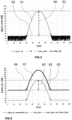
- the audio signal generated in accordance with embodiments using the dynamic range compression technique Dyn_Sin of the detection signal supplied as input, with a compression rate adapted to match the useful dynamic range Dyn_Sout of the output signal, which is represented by graph 81 of the figure 8 respects the variations of the amplitude of the detection signal.
- the curve 81 of the figure 8 corresponds to curve 51 of the figure 5 , by being "picked up", i.e. compressed in the range of values (on the scale in decibels) between 30 dB SPL (A) and 80 dB SPL (A).
- curve 71 of the figure 7 and curve 81 of the figure 8 are superimposed on the figure 9 .
- the target detection signal is segmented so as to define several portions or zones in which there can be associated compression rates, called local dynamic range compression rates, which can be different from one zone to another.
- the graph shows, on the ordinate, the level of the audio signal in decibels (dB), denoted “Audio_Lev” as a function of the amplitude (in dB) of the target detection signal, denoted “Signal_Amp” and represented on the abscissa.
- the reference level giving 0 dB corresponds to the maximum level which is comfortable for the user, and which the user can adjust with the volume control.
- the dynamic Dyn_Sout of the audio signal is here 40 dB, between ⁇ 40 dB and 0 dB.
- the detection signal is segmented into three portions or zones, respectively Z1, Z2 and Z3, corresponding to respective intervals of its dynamic range, for example two-by-two contiguous zones.
- this is not limiting.
- the dynamics of the target detection signal can be subdivided into only two portions, or conversely into four or more portions.
- the first portion corresponds to the so-called “false signals” zone which corresponds (for example) to a dynamic range of 10 to 20 dB above the detection threshold.
- a second portion Z2 corresponds to the zone of signals called “average signals", from the end of zone Z1 up to, for example, 60dB above the detection threshold, followed by the portion Z3 corresponding to the zone of strong signals, after 60 dB above said threshold.
- the portions of the dynamics corresponding to the first and the last zone, Z1 and Z3 respectively, can thus be modified by local dynamic compression ratios lower than that which is applied to the portion of the dynamics corresponding to the zone Z2, with the aim, for example, of magnifying the target signals in the zone Z2 of the average signals.
- the various zones can be defined by linear segments. You can also use a smoothing to erase the breaks in slope at the "borders" between two contiguous zones, for example with a Spline type smoothing.
- the global dynamic compression that is sought does not prevent at least one local dynamic modification rate from being greater than or equal to unity.
- one or more zones of the dynamic range of the detection signal can be locally extended (we then speak of extension or dynamic range expansion, instead of compression of dynamic), although the dynamic is globally compressed, that is to say if we consider globally the entirety of this dynamic.
- At least some portions of the dynamics can be associated with respective timbres of the audio signal.
- each zone among zones Z1, Z2, Z3 and Zsat can be associated with a different timbre.
- the change in timbre can be done gradually when passing from one portion of the dynamics to another. In other words, the change in timbre of the acoustic signal between two contiguous portions of the dynamics of the detection signal is progressive from one to the other.
- the segmentation described above also makes it possible to apply the spectral enhancements associated with the target discrimination methods in a differentiated manner, according to the level of the received signal and therefore according to the dynamic zone in which it is located, it being observed that the Target discrimination accuracy is generally degraded for weak signals and for saturated signals.
- Several implementations can be considered, which are specified in the following.
- the oscillator that generates the final sound proceeds by wavetable reading.
- Each zone border is associated with a waveform calculated beforehand, for example according to a desired spectral content.
- the oscillator that generates the sound performs an interpolation between the two waveforms defined at the border of the activated zone. It is thus possible, for example, to reserve for the zone Z1 of the "false signals" (zone of the weakest signals, lost in the noise) a waveform whose spectrum is relatively "soft” and to reserve a waveform to the spectrum more "aggressive" for the signals in the zone Z3 of the dynamics whose amplitude is the highest. Similarly, waveforms reminiscent of the spectrum of saturated signals can be used for the strongest signals.
- variable spectral modification according to the level is to allow the ear of the user to improve the perception of level, without having recourse to a variation of frequency according to the level, which makes it possible to reserve the possibility of using a frequency variation in connection with discrimination information.
- Waveform reading makes it possible to generate various sounds, and even, with a single oscillator, to simulate third or fifth chords by generating waveform tables whose fundamental components are set to harmonics 4 , 5, 6 signal.
- the spectral change inside a zone can be obtained by subtracting two waveforms whose phase depends on the level of the detection signal at the input of the device.
- This synthesis mode allows the generation of signals of the pulse type of variable widths (pulse width modulation or PWM) by subtracting two signals of the “ sawtooth ” (or SAW) type . It is thus possible to generate signals whose spectral content varies radically according to the phase shift value, from a practically "flat" spectrum for low duty cycles, to a "square" signal (spectrum with a decrease in 1/f, without harmonics odd) for a duty cycle of 50% (see the spectra associated with the PWM signals above).
- An advantage of this type of synthesis is that it makes it possible to generate signals similar to PWM signals (with recognizable spectral shifts) while having control of the overall richness of the spectrum by acting on the basic signals (initially signals "sawtooth") used for subtraction.
- the spectral change within an area can be obtained by frequency modulations of the oscillator used for sound generation, using methods worked out by John Chowning in 1967.
- the spectral change within an area can be obtained by subtractive synthesis, for example by inserting into the path of the audio signal a filter whose characteristics are dynamically varied.
- the spectral changes can be obtained by additive synthesis, for example by implementing multiple audio oscillators whose mixture can be determined according to the desired frequency spectrum.
Landscapes
- Physics & Mathematics (AREA)
- Life Sciences & Earth Sciences (AREA)
- Engineering & Computer Science (AREA)
- General Physics & Mathematics (AREA)
- Electromagnetism (AREA)
- Remote Sensing (AREA)
- Environmental & Geological Engineering (AREA)
- Geology (AREA)
- General Life Sciences & Earth Sciences (AREA)
- Geophysics (AREA)
- Signal Processing (AREA)
- Acoustics & Sound (AREA)
- Tone Control, Compression And Expansion, Limiting Amplitude (AREA)
- Circuit For Audible Band Transducer (AREA)
- Compression, Expansion, Code Conversion, And Decoders (AREA)
- Geophysics And Detection Of Objects (AREA)
Applications Claiming Priority (1)
| Application Number | Priority Date | Filing Date | Title |
|---|---|---|---|
| FR2111596A FR3128795B1 (fr) | 2021-11-01 | 2021-11-01 | Restitution audio d’un signal de détection électromagnétique de métaux |
Publications (3)
| Publication Number | Publication Date |
|---|---|
| EP4174530A1 true EP4174530A1 (de) | 2023-05-03 |
| EP4174530B1 EP4174530B1 (de) | 2025-08-20 |
| EP4174530C0 EP4174530C0 (de) | 2025-08-20 |
Family
ID=81327455
Family Applications (1)
| Application Number | Title | Priority Date | Filing Date |
|---|---|---|---|
| EP22204318.4A Active EP4174530B1 (de) | 2021-11-01 | 2022-10-28 | Audiowiedergabe eines elektromagnetischen metalldetektionssignals |
Country Status (4)
| Country | Link |
|---|---|
| US (1) | US20230161067A1 (de) |
| EP (1) | EP4174530B1 (de) |
| CN (1) | CN116074691A (de) |
| FR (1) | FR3128795B1 (de) |
Citations (6)
| Publication number | Priority date | Publication date | Assignee | Title |
|---|---|---|---|---|
| US4594559A (en) | 1983-09-12 | 1986-06-10 | Bernzweig David S | Metal detector audio amplifier |
| US4644290A (en) | 1983-09-12 | 1987-02-17 | Bernzweig David S | Metal detector audio amplifier |
| DE4212363A1 (de) * | 1992-04-13 | 1993-10-14 | Klaus Ebinger Ing | Metalldetektor |
| DE29811404U1 (de) * | 1998-06-25 | 1998-09-10 | Fa. Ing. Klaus Ebinger, 51149 Köln | Sondenvorrichtung |
| WO2000015001A2 (en) * | 1998-09-09 | 2000-03-16 | Sonic Innovations, Inc. | Hearing aid device incorporating signal processing techniques |
| DE102005018590A1 (de) * | 2005-04-21 | 2006-12-07 | Mesutronic Gerätebau GmbH | Gerät zur Erkennung von metallischen Teilchen in einem Produktstrom |
Family Cites Families (6)
| Publication number | Priority date | Publication date | Assignee | Title |
|---|---|---|---|---|
| US6072885A (en) * | 1994-07-08 | 2000-06-06 | Sonic Innovations, Inc. | Hearing aid device incorporating signal processing techniques |
| US7078911B2 (en) * | 2003-02-06 | 2006-07-18 | Cehelnik Thomas G | Patent application for a computer motional command interface |
| EP2213226B1 (de) * | 2009-02-03 | 2012-06-13 | Heinrich Zimmermann | System, Verfahren und Vorrichtung zur Hördarstellung rhythmischer Parameter |
| AU2013200451C1 (en) * | 2011-11-03 | 2014-04-10 | Minelab Electronics Pty Limited | Method for separating target signals from unwanted signals in a metal detector |
| AU2013201248B2 (en) * | 2012-03-06 | 2014-02-27 | Minelab Electronics Pty Limited | A method for displaying metal detection information |
| JP7193772B2 (ja) * | 2018-03-23 | 2022-12-21 | ヤマハ株式会社 | ダイナミクス処理方法 |
-
2021
- 2021-11-01 FR FR2111596A patent/FR3128795B1/fr active Active
-
2022
- 2022-10-28 EP EP22204318.4A patent/EP4174530B1/de active Active
- 2022-10-31 US US17/977,984 patent/US20230161067A1/en active Pending
- 2022-11-01 CN CN202211357107.2A patent/CN116074691A/zh active Pending
Patent Citations (6)
| Publication number | Priority date | Publication date | Assignee | Title |
|---|---|---|---|---|
| US4594559A (en) | 1983-09-12 | 1986-06-10 | Bernzweig David S | Metal detector audio amplifier |
| US4644290A (en) | 1983-09-12 | 1987-02-17 | Bernzweig David S | Metal detector audio amplifier |
| DE4212363A1 (de) * | 1992-04-13 | 1993-10-14 | Klaus Ebinger Ing | Metalldetektor |
| DE29811404U1 (de) * | 1998-06-25 | 1998-09-10 | Fa. Ing. Klaus Ebinger, 51149 Köln | Sondenvorrichtung |
| WO2000015001A2 (en) * | 1998-09-09 | 2000-03-16 | Sonic Innovations, Inc. | Hearing aid device incorporating signal processing techniques |
| DE102005018590A1 (de) * | 2005-04-21 | 2006-12-07 | Mesutronic Gerätebau GmbH | Gerät zur Erkennung von metallischen Teilchen in einem Produktstrom |
Non-Patent Citations (5)
| Title |
|---|
| ANONYMOUS: "DEUS V5 - USER'S MANUAL", 4 July 2018 (2018-07-04), XP055936228, Retrieved from the Internet <URL:https://smhttp-ssl-37061.nexcesscdn.net/media/_docs/Manual/EN/XP_DEUS_5_Manual_EN.pdf> [retrieved on 20220628] * |
| GENE FERGUSON ET AL.: "Auditory signais for enhanced operator performance with hand-held mine detector", DÉTECTION AND REMEDIATION TECHNOLOGIES FOR MINES AND MINELIKE TARGETS V, vol. 4038, 2000 |
| GIFFORD VINCE: "Outlaw Operator Instruction Manual", 12 June 2012 (2012-06-12), XP055933183, Retrieved from the Internet <URL:https://www.metaldetector.com/media/_docs/Manual/EN/Tesoro_Outlaw_Manual.pdf> [retrieved on 20220620] * |
| HARRY NEUTEBOOM ET AL: "A DSP-Based Hearing Instrument IC", IEEE JOURNAL OF SOLID-STATE CIRCUITS, IEEE, USA, vol. 32, no. 11, 1 November 1997 (1997-11-01), XP011060607, ISSN: 0018-9200 * |
| NANCY L. VAUSE: "Auditory issues in Hand-Held Landmine Detector", DÉTECTION AND REMEDIATION TECHNOLOQJES FOR MINES AND MINELIKE TARGETS IV, vol. 3710, April 1999 (1999-04-01) |
Also Published As
| Publication number | Publication date |
|---|---|
| US20230161067A1 (en) | 2023-05-25 |
| CN116074691A (zh) | 2023-05-05 |
| FR3128795A1 (fr) | 2023-05-05 |
| FR3128795B1 (fr) | 2023-12-22 |
| EP4174530B1 (de) | 2025-08-20 |
| EP4174530C0 (de) | 2025-08-20 |
Similar Documents
| Publication | Publication Date | Title |
|---|---|---|
| CN108196683B (zh) | 利用波形的声音到触觉效应转换系统 | |
| EP2920783B1 (de) | Verfahren und system zur erzeugung von schallfeldern | |
| US10601385B2 (en) | Recording level adjustment using a distance to a sound source | |
| KR101880764B1 (ko) | 파형을 이용한 사운드 대 햅틱 효과 변환 시스템 | |
| RU2569914C2 (ru) | Возбуждение параметрических громкоговорителей | |
| JP2009188474A5 (de) | ||
| JP2005318598A (ja) | 信号処理におけるまたはそれに関する改善 | |
| EP0994464A1 (de) | Verfahren und Vorrichtung zur Vergrösserung der Bandbreite von einem schmalbandigen Signal und solch eine Vorrichtung aufweisende Telefoneinrichtung | |
| CN106560722A (zh) | 基于超声噪声的声纳 | |
| EP2113913A1 (de) | Verfahren und System zur Wiederherstellung von Niedrigfrequenzen in einem Audiosignal | |
| EP4174530B1 (de) | Audiowiedergabe eines elektromagnetischen metalldetektionssignals | |
| EP3050319B1 (de) | Hochgenaue schallwiedergabevorrichtung | |
| CN109541608A (zh) | 一种电子设备及其声波测距方法 | |
| US8254590B2 (en) | System and method for intelligibility enhancement of audio information | |
| US8223990B1 (en) | Audio noise attenuation | |
| FR3120449A1 (fr) | Procédé de détermination d’une direction de propagation d’une source sonore par création de signaux sinusoïdaux à partir des signaux sonores reçus par des microphones. | |
| Hots et al. | Loudness of sounds with a subcritical bandwidth: A challenge to current loudness models? | |
| JP2007189627A (ja) | 音響装置 | |
| WO2007026305A2 (en) | Method of amplitude modulating a message signal in the audible frequency range onto a carrier signal in the ultrasonic frequency range | |
| JP5573288B2 (ja) | 収音装置および放収音装置 | |
| CN106797517A (zh) | 用于净化音频信号的多耳mmse分析技术 | |
| FR2757301A1 (fr) | Dispositif d'avertissement de la presence d'un signal | |
| WO2021118352A1 (en) | Generating an audio signal associated with a virtual sound source | |
| JP6124432B2 (ja) | 情報送信装置、情報送信プログラム、情報受信装置、情報受信プログラム、及び情報通信方法 | |
| CN103688555B (zh) | 用于减少扬声器的失真的方法及装置、音频再现设备 |
Legal Events
| Date | Code | Title | Description |
|---|---|---|---|
| PUAI | Public reference made under article 153(3) epc to a published international application that has entered the european phase |
Free format text: ORIGINAL CODE: 0009012 |
|
| STAA | Information on the status of an ep patent application or granted ep patent |
Free format text: STATUS: THE APPLICATION HAS BEEN PUBLISHED |
|
| AK | Designated contracting states |
Kind code of ref document: A1 Designated state(s): AL AT BE BG CH CY CZ DE DK EE ES FI FR GB GR HR HU IE IS IT LI LT LU LV MC ME MK MT NL NO PL PT RO RS SE SI SK SM TR |
|
| STAA | Information on the status of an ep patent application or granted ep patent |
Free format text: STATUS: REQUEST FOR EXAMINATION WAS MADE |
|
| 17P | Request for examination filed |
Effective date: 20231102 |
|
| RBV | Designated contracting states (corrected) |
Designated state(s): AL AT BE BG CH CY CZ DE DK EE ES FI FR GB GR HR HU IE IS IT LI LT LU LV MC ME MK MT NL NO PL PT RO RS SE SI SK SM TR |
|
| GRAP | Despatch of communication of intention to grant a patent |
Free format text: ORIGINAL CODE: EPIDOSNIGR1 |
|
| STAA | Information on the status of an ep patent application or granted ep patent |
Free format text: STATUS: GRANT OF PATENT IS INTENDED |
|
| RIC1 | Information provided on ipc code assigned before grant |
Ipc: H03G 3/30 20060101ALI20250220BHEP Ipc: G01V 3/165 20060101AFI20250220BHEP |
|
| INTG | Intention to grant announced |
Effective date: 20250311 |
|
| RAP3 | Party data changed (applicant data changed or rights of an application transferred) |
Owner name: SARL XPLORER |
|
| RIN1 | Information on inventor provided before grant (corrected) |
Inventor name: VERN, JEAN-LOUIS |
|
| GRAS | Grant fee paid |
Free format text: ORIGINAL CODE: EPIDOSNIGR3 |
|
| GRAA | (expected) grant |
Free format text: ORIGINAL CODE: 0009210 |
|
| STAA | Information on the status of an ep patent application or granted ep patent |
Free format text: STATUS: THE PATENT HAS BEEN GRANTED |
|
| AK | Designated contracting states |
Kind code of ref document: B1 Designated state(s): AL AT BE BG CH CY CZ DE DK EE ES FI FR GB GR HR HU IE IS IT LI LT LU LV MC ME MK MT NL NO PL PT RO RS SE SI SK SM TR |
|
| REG | Reference to a national code |
Ref country code: GB Ref legal event code: FG4D Free format text: NOT ENGLISH |
|
| REG | Reference to a national code |
Ref country code: CH Ref legal event code: EP |
|
| REG | Reference to a national code |
Ref country code: IE Ref legal event code: FG4D Free format text: LANGUAGE OF EP DOCUMENT: FRENCH |
|
| REG | Reference to a national code |
Ref country code: DE Ref legal event code: R096 Ref document number: 602022019730 Country of ref document: DE |
|
| U01 | Request for unitary effect filed |
Effective date: 20250919 |
|
| U07 | Unitary effect registered |
Designated state(s): AT BE BG DE DK EE FI FR IT LT LU LV MT NL PT RO SE SI Effective date: 20250926 |
|
| U20 | Renewal fee for the european patent with unitary effect paid |
Year of fee payment: 4 Effective date: 20251028 |
|
| PG25 | Lapsed in a contracting state [announced via postgrant information from national office to epo] |
Ref country code: IS Free format text: LAPSE BECAUSE OF FAILURE TO SUBMIT A TRANSLATION OF THE DESCRIPTION OR TO PAY THE FEE WITHIN THE PRESCRIBED TIME-LIMIT Effective date: 20251220 |
|
| PG25 | Lapsed in a contracting state [announced via postgrant information from national office to epo] |
Ref country code: NO Free format text: LAPSE BECAUSE OF FAILURE TO SUBMIT A TRANSLATION OF THE DESCRIPTION OR TO PAY THE FEE WITHIN THE PRESCRIBED TIME-LIMIT Effective date: 20251120 |
|
| PG25 | Lapsed in a contracting state [announced via postgrant information from national office to epo] |
Ref country code: HR Free format text: LAPSE BECAUSE OF FAILURE TO SUBMIT A TRANSLATION OF THE DESCRIPTION OR TO PAY THE FEE WITHIN THE PRESCRIBED TIME-LIMIT Effective date: 20250820 |
|
| PG25 | Lapsed in a contracting state [announced via postgrant information from national office to epo] |
Ref country code: GR Free format text: LAPSE BECAUSE OF FAILURE TO SUBMIT A TRANSLATION OF THE DESCRIPTION OR TO PAY THE FEE WITHIN THE PRESCRIBED TIME-LIMIT Effective date: 20251121 |
|
| PG25 | Lapsed in a contracting state [announced via postgrant information from national office to epo] |
Ref country code: PL Free format text: LAPSE BECAUSE OF FAILURE TO SUBMIT A TRANSLATION OF THE DESCRIPTION OR TO PAY THE FEE WITHIN THE PRESCRIBED TIME-LIMIT Effective date: 20250820 |
|
| PG25 | Lapsed in a contracting state [announced via postgrant information from national office to epo] |
Ref country code: RS Free format text: LAPSE BECAUSE OF FAILURE TO SUBMIT A TRANSLATION OF THE DESCRIPTION OR TO PAY THE FEE WITHIN THE PRESCRIBED TIME-LIMIT Effective date: 20251120 |
|
| PG25 | Lapsed in a contracting state [announced via postgrant information from national office to epo] |
Ref country code: ES Free format text: LAPSE BECAUSE OF FAILURE TO SUBMIT A TRANSLATION OF THE DESCRIPTION OR TO PAY THE FEE WITHIN THE PRESCRIBED TIME-LIMIT Effective date: 20250820 |
|
| PG25 | Lapsed in a contracting state [announced via postgrant information from national office to epo] |
Ref country code: SM Free format text: LAPSE BECAUSE OF FAILURE TO SUBMIT A TRANSLATION OF THE DESCRIPTION OR TO PAY THE FEE WITHIN THE PRESCRIBED TIME-LIMIT Effective date: 20250820 |
|
| PG25 | Lapsed in a contracting state [announced via postgrant information from national office to epo] |
Ref country code: CZ Free format text: LAPSE BECAUSE OF FAILURE TO SUBMIT A TRANSLATION OF THE DESCRIPTION OR TO PAY THE FEE WITHIN THE PRESCRIBED TIME-LIMIT Effective date: 20250820 |
|
| PG25 | Lapsed in a contracting state [announced via postgrant information from national office to epo] |
Ref country code: SK Free format text: LAPSE BECAUSE OF FAILURE TO SUBMIT A TRANSLATION OF THE DESCRIPTION OR TO PAY THE FEE WITHIN THE PRESCRIBED TIME-LIMIT Effective date: 20250820 |