EP4174498B1 - Messsystem zur analyse von hochfrequenzsignalen und betriebsverfahren dafür - Google Patents
Messsystem zur analyse von hochfrequenzsignalen und betriebsverfahren dafür Download PDFInfo
- Publication number
- EP4174498B1 EP4174498B1 EP21204629.6A EP21204629A EP4174498B1 EP 4174498 B1 EP4174498 B1 EP 4174498B1 EP 21204629 A EP21204629 A EP 21204629A EP 4174498 B1 EP4174498 B1 EP 4174498B1
- Authority
- EP
- European Patent Office
- Prior art keywords
- measurement system
- reflective
- pcb
- planar face
- light
- Prior art date
- Legal status (The legal status is an assumption and is not a legal conclusion. Google has not performed a legal analysis and makes no representation as to the accuracy of the status listed.)
- Active
Links
Images

Classifications
-
- G—PHYSICS
- G01—MEASURING; TESTING
- G01R—MEASURING ELECTRIC VARIABLES; MEASURING MAGNETIC VARIABLES
- G01R29/00—Arrangements for measuring or indicating electric quantities not covered by groups G01R19/00 - G01R27/00
- G01R29/08—Measuring electromagnetic field characteristics
- G01R29/0864—Measuring electromagnetic field characteristics characterised by constructional or functional features
- G01R29/0878—Sensors; antennas; probes; detectors
- G01R29/0885—Sensors; antennas; probes; detectors using optical probes, e.g. electro-optical, luminescent, glow discharge, or optical interferometers
-
- G—PHYSICS
- G01—MEASURING; TESTING
- G01R—MEASURING ELECTRIC VARIABLES; MEASURING MAGNETIC VARIABLES
- G01R1/00—Details of instruments or arrangements of the types included in groups G01R5/00 - G01R13/00 and G01R31/00
- G01R1/20—Modifications of basic electric elements for use in electric measuring instruments; Structural combinations of such elements with such instruments
- G01R1/24—Transmission-line, e.g. waveguide, measuring sections, e.g. slotted section
-
- G—PHYSICS
- G01—MEASURING; TESTING
- G01R—MEASURING ELECTRIC VARIABLES; MEASURING MAGNETIC VARIABLES
- G01R33/00—Arrangements or instruments for measuring magnetic variables
- G01R33/02—Measuring direction or magnitude of magnetic fields or magnetic flux
- G01R33/032—Measuring direction or magnitude of magnetic fields or magnetic flux using magneto-optic devices, e.g. Faraday or Cotton-Mouton effect
-
- G—PHYSICS
- G01—MEASURING; TESTING
- G01R—MEASURING ELECTRIC VARIABLES; MEASURING MAGNETIC VARIABLES
- G01R33/00—Arrangements or instruments for measuring magnetic variables
- G01R33/20—Arrangements or instruments for measuring magnetic variables involving magnetic resonance
- G01R33/24—Arrangements or instruments for measuring magnetic variables involving magnetic resonance for measuring direction or magnitude of magnetic fields or magnetic flux
- G01R33/26—Arrangements or instruments for measuring magnetic variables involving magnetic resonance for measuring direction or magnitude of magnetic fields or magnetic flux using optical pumping
Definitions
- the present disclosure relates to signal analysis in microwave communication, and in particular to a measurement system for analysing RF signals and a method of operating the measurement system.
- Atom-based quantum effects may be used in developing quantum sensors for various physical quantities, as is known in the art.
- atomic vapor may exhibit sensitive responses to external electromagnetic radio-frequency (RF) fields, ranging from several to hundreds of gigahertz (GHz). This coincides with a microwave frequency range between 300 MHz and 300 GHz, respectively.
- RF radio-frequency
- the present disclosure aims to improve RF signal analysis of the background art.
- An objective is to make RF signal analysis more sensitive, more robust and less burdensome.
- a first aspect of the present disclosure relates to a measurement system for analysing RF signals.
- the measurement system comprises a optically transparent enclosure comprising an optically pumpable gas, and a printed circuit board, PCB, comprising an electrical transmission line for guiding the RF signal to be analyzed through the enclosure and a reflective planar face.
- the measurement system further comprises an optical pump for emitting preferably coherent light onto the reflective planar face, and a detector for detecting an optical property of the emitted light being reflected by the reflective planar face.
- the gas may comprise an alkali metal, preferably Rubidium.
- the transmission line may comprise an insulator layer sandwiched between conductor layers.
- the transmission line may include one of: a microstrip, and a coplanar waveguide with ground.
- the transmission line may include one of: a reflective coating, and a polished conductor layer.
- the reflective coating may comprise one of: a reflective dielectric coating comprising a quarterwave stack of alternating high and low index layers, and a reflective metal coating.
- the reflective planar face of the PCB (12A, 12B) may have a reflectance for the emitted light in excess of 80%.
- the emitted light may have a wavelength in accordance with an energy transition of the gas, preferably 780 nm or 795 nm.
- the optical pump may be arranged to emit the light in a continuous wave, CW, mode or in a pulsed mode.
- the optical pump may be arranged to emit the light perpendicularly to a propagation direction of the RF signal.
- Propagation directions of the emitted light and the reflected light may form an intermediate angle of at most 174°, preferably at most 160°, more preferably at most 140°, and most preferably 90°.
- the detector and the optical pump may be arranged non-coaxially in accordance with the intermediate angle.
- the detector may comprise one of: a photodiode, and a camera.
- the PCB may comprise two electrical transmission lines on respective reflective planar faces of the PCB; and the measurement system may comprise two optical pumps for emitting light in accordance with an energy transition of the gas, and two detectors for detecting an optical property of the emitted light emitted by the respective optical pump and reflected by the respective reflective planar face.
- a second aspect of the present disclosure relates to a method of operating a measurement system for analysing RF signals.
- the measurement system comprises a optically transparent enclosure comprising an optically pumpable gas, a printed circuit board, PCB, comprising an electrical transmission line, an optical pump, and a detector.
- the PCB comprises a reflective planar face.
- the method comprises guiding the RF signal to be analyzed through the enclosure via the transmission line, emitting preferably coherent light onto the reflective planar face, and detecting an optical property of the emitted light being reflected by the reflective planar face.
- the present disclosure proposes using a surface of a PCB to reflect light / laser beams, coating and/or polishing the surface of the PCB to improve reflectivity, and choosing the right material for optimizing reflectivity for a particular wavelength.
- FIG. 1 illustrates a first embodiment of a measurement system 1 according to the present disclosure for analysing RF signals.
- the measurement system 1 comprises an optically transparent enclosure 11 comprising an optically pumpable gas.
- the optically transparent enclosure 11 may comprise an optically transparent body or window made of optically transparent material such as borosilicate glass or aluminosciliate glass.
- the enclosure 11 may be a gas cell / atomic vapor cell.
- the gas may comprise an alkali metal, preferably Rubidium.
- Cesium may be used, or even non-alkali metals such as Helium.
- the measurement system 1 further comprises - without loss of generality - a PCB 12A comprising an electrical transmission line 121-123 for guiding the RF signal to be analyzed through the enclosure 11.
- the transmission line 121-123 may comprise an insulator layer 122 sandwiched between conductor layers 121, 123.
- the conductor 121 is configured to guide the RF signal to be analyzed through the enclosure 11, and any conductors 123 may relate to a ground potential. Responsive to RF signal propagation along the conductor 121, a non-radiative electromagnetic field emerges in a near-field region of the same.
- a magnetic portion thereof is illustrated in FIGs. 2 and 3 as closed field lines around the respective conductor 121, whereas field lines of an electric portion thereof (not shown) run perpendicularly to the field lines of the magnetic portion and terminate perpendicularly in the conductors 121, 123.
- the transmission line 121-123 may include one of: a microstrip (see FIG. 2 below), and a coplanar waveguide with ground (see FIG. 3 below).
- the emerging non-radiative electromagnetic field should be able to extend outside the PCB 12A, where the electromagnetic field of the RF signal may interact with the gas particles of the enclosure 11. More specifically, a respective absorption rate of frequency components of the RF signal increases with a respective energy of the frequency components. As such, for a given duration of the emerging non-radiative electromagnetic field, high-energy frequency components achieve a more exhaustive population inversion of the gas particles from the initial state/level to the excited state/level than low-energy frequency components, corresponding to intensity-dependent filtering.
- the PCB 12A further comprises a reflective planar face.
- the PCB 12A, 12B may include one of: a reflective coating 124; and a polished conductor layer 121, 123.
- the reflective coating 124 may comprise one of: a reflective dielectric coating comprising a quarterwave stack of alternating high and low index layers, and a reflective metal coating.
- a spectral width of the reflection band and the achievable reflectivity for a given number of layer pairs depends on the ratio of the refractive indices of the layer materials. For example, a large refractive index ratio yields a broad reflection band.
- reflective metallic coatings a surface of which may be oxidation-protected for maintaining a reflection property of the same.
- the reflective planar face of the PCB 12A may have a reflectance for the emitted light in excess of 80%. This may be achieved by reflective dielectric coatings based on a quarterwave stack comprising ⁇ 5 pairs of Ta 2 O 5 /SiO 2 in the reflection band 700-900nm. Similar results may be obtained using pairs of TiO 2 /SiO 2 layers. On the other hand, the reflective dielectric coatings should be made as thin as possible in order not to shield the emerging near field. A reflectancy in excess of 80% in the reflection band 700-900nm may also be achieved by reflective metallic surfaces, e.g., polished conductor layers 121, 123 made of one of: aluminum, copper, silver, and gold.
- reflective metallic surfaces e.g., polished conductor layers 121, 123 made of one of: aluminum, copper, silver, and gold.
- the measurement system 1 further comprises an optical pump 13 for emitting preferably coherent light onto the reflective planar face.
- an optical pump 13 for emitting preferably coherent light onto the reflective planar face.
- a laser source may be deployed for emitting coherent light.
- optical pumping and optical readout may realized by a single pump (as described in this implementation) or by separate pumps. In a setup with separate optical pumps, it would be beneficial if both beams overlap well with the electromagnetic field of the RF signal. If sensing is performed using Rydberg atoms, at least one more optical pump is needed for excitation to the Rydberg state.
- the optical pump 13 may be arranged to emit the light in a continuous wave, CW, mode or in a pulsed mode.
- the emitted light may have a wavelength in accordance with an energy transition of the gas, preferably 780 nm or 795 nm specifically for Rubidium, such that the atoms of the gas may be pumped from a ground energy state/level to highly excited initial energy states/levels wherein an outermost electron is substantially farther away from a nucleus as in the initial energy state/level.
- the initial energy state of a quantum system based on the atoms of the gas may comprise a Rydberg state.
- Rydberg states have multiple energy transitions in the GHz-THz range so that they are sensitive to excitation by magnetic fields, and particularly by electric fields, in a wide frequency range. Excitation to Rydberg state may be achieved using at least one further optical pump in addition to said 780/795 nm optical pumps.
- the optical pump 13 may be arranged to emit the light perpendicularly to a propagation direction of the RF signal.
- the RF signal to be analyzed propagates perpendicular to a drawing plane of FIG. 1 , whereas the emitted light propagates within the drawing plane.
- Propagation directions of the emitted light and the reflected light may form an intermediate angle 15 of at most 174°, preferably at most 160°, more preferably at most 140°, and most preferably 90°.
- directing a laser beam closely along, i.e., substantially parallel to, a surface as known in the art should be avoided.
- the measurement system 1 further comprises a detector 14 for detecting an optical property of the emitted light being reflected by the reflective planar face.
- the optical property may comprise an optical intensity or a photon count.
- the detector 14 may comprise one of: a photodiode for punctiform detection, and a camera for spatially resolved detection in accordance with an interaction of the emerging near field of the RF signal to be analyzed and the incident/reflected light beams having spatially resolved intensities (see an exemplary beam intensity profile indicated in FIG. 1 between the optical pump 13 and the enclosure 11).
- the spatially resolved optical pumping results in spatially resolved population of the initial energy state/level of the quantum system formed by the optically pumpable gas, and thus a spatially resolved (cap)ability of the quantum system to be ionized easily by absorption when exposed to external electro-magnetic RF fields.
- Such a (near) field may be induced around the electrical transmission line 121-123 when guiding an RF signal to be analyzed through the enclosure 11.
- the detector 14 and the optical pump 13 may be arranged non-coaxially in accordance with the intermediate angle 15.
- An intermediate angle of 90° may simplify the non-coaxial arrangement, whereas larger intermediate angles 15 of less than 180° may further improve a reflection property of the reflective planar face.
- only the beam for optical readout needs to be imaged/reflected to the optical detector.
- Presence of a magnetic or electric field may be used to cause splitting/shifts of the atomic energy levels in accordance with Zeeman or Stark splitting, which ensures availability of gas particles in an initial state for each frequency in a desired frequency range, such as an RF / microwave frequency range between 300 MHz and 300 GHz, respectively.
- a desired frequency range such as an RF / microwave frequency range between 300 MHz and 300 GHz, respectively.
- filtering may be possible up to the THz regime.
- Zeeman splitting may refer to splitting of a spectral line into several components in the presence of a static magnetic field.
- Stark splitting the electric-field analogue of Zeeman splitting, may refer to splitting of a spectral line into several components in the presence of a static electric field.
- FIGs. 2, 3 illustrate various embodiments of a PCB 12A, 12B according to the present disclosure for guiding RF signals to be analyzed through an enclosure 11 of the measurement system 1.
- the depicted PCBs 12A, 12B respectively comprise an electrical transmission line 121-123 for guiding the RF signal to be analyzed through the enclosure 11 of the measurement system 1.
- the respective transmission line 121-123 may comprise an insulator layer 122 sandwiched between conductor layers 121, 123.
- the respective transmission line 121-123 includes a microstrip in FIG. 2 , and a coplanar waveguide with ground in FIG. 3 .
- the respective PCB 12A, 12B comprises a reflective planar face in accordance with what has been set out above.
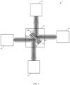
- FIG. 4 illustrates a second embodiment of a measurement system 1 according to the present disclosure for analysing RF signals.
- the PCB 12A, 12B may comprise two electrical transmission lines 121-123 on respective reflective planar faces of the PCB 12A, 12B.
- the PCB 12B comprises two coplanar waveguides with ground arranged back-to-back.
- this embodiment of the measurement system 1 may comprise two optical pumps 13 for emitting light in accordance with an energy transition of the gas, and two detectors 14 for detecting an optical property of the emitted light emitted by the respective optical pump 13 and reflected by the respective reflective planar face. This may reduce a space requirement of such a twin quantum sensor.
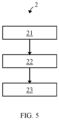
- FIG. 5 illustrates an embodiment of a method of operating the measurement systems 1 of FIGs. 1 and 2 .
- the measurement system 1 to be operated comprises a optically transparent enclosure 11 comprising an optically pumpable gas, a printed circuit board, PCB 12A, 12B comprising an electrical transmission line 121-123, an optical pump 13, and a detector 14.
- the PCB 12A, 12B further comprises a reflective planar face.
- the method 2 comprises guiding 21 the RF signal to be analyzed through the enclosure 11 via the transmission line 121-123.
- the method 2 comprises emitting 22 preferably coherent light onto the reflective planar face.
- the method 2 comprises detecting 23 an optical property of the emitted light being reflected by the planar face.
Landscapes
- Physics & Mathematics (AREA)
- General Physics & Mathematics (AREA)
- Electromagnetism (AREA)
- Engineering & Computer Science (AREA)
- Power Engineering (AREA)
- Condensed Matter Physics & Semiconductors (AREA)
- Investigating Or Analysing Materials By Optical Means (AREA)
- Nonlinear Science (AREA)
- Optics & Photonics (AREA)
- Plasma & Fusion (AREA)
Claims (15)
- Messsystem (1) zum Analysieren von HF-Signalen, umfassendein optisch transparentes Gehäuse (11), umfassend ein optisch pumpbares Gas;eine Leiterplatte, PCB (12A, 12B), umfassend eine elektrische Übertragungsleitung (121-123) zum Führen des HF-Signals, das durch das Gehäuse (11) zu analysieren ist, und eine reflektierende planare Fläche;eine optische Pumpe (13) zum Emittieren von vorzugsweise kohärentem Licht auf die reflektierende planare Fläche; undeinen Detektor (14) zum Erfassen einer optischen Eigenschaft des emittierten Lichts, das durch die reflektierende planare Fläche reflektiert wird.
- Messsystem (1) nach Anspruch 1,
das Gas umfassend ein Alkalimetall, vorzugsweise Rubidium. - Messsystem (1) nach einem der vorstehenden Ansprüche,
die Übertragungsleitung (121-123) umfassend eine Isolatorschicht (122), die zwischen den Leiterschichten (121, 123) dazwischenliegend angeordnet ist. - Messsystem (1) nach Anspruch 3,
wobei die Übertragungsleitung (121-123) eines einschließt von:- einem Mikrostreifen; und- einem koplanaren Wellenleiter mit Masse. - Messsystem (1) nach einem der vorstehenden Ansprüche, wobei die PCB (12A, 12B) eines einschließt von:- einer reflektierenden Beschichtung (124); und- einer polierten Leiterschicht (121, 123).
- Messsystem (1) nach Anspruch 5,
die reflektierende Beschichtung (124) umfassend eines von:- einer reflektierenden dielektrischen Beschichtung, umfassend einen Viertelwellenstapel von abwechselnden Schichten mit hohem und niedrigem Index; und- einer reflektierenden Metallbeschichtung. - Messsystem (1) nach einem der vorstehenden Ansprüche,
wobei die reflektierende planare Fläche der PCB (12A, 12B) einen Reflexionsgrad für das emittierte Licht im Überschuss von 80 % aufweist. - Messsystem (1) nach einem der vorstehenden Ansprüche,
wobei das emittierte Licht eine Wellenlänge gemäß einem Energieübergang des Gases, vorzugsweise 780 nm oder 795 nm, aufweist. - Messsystem (1) nach einem der vorstehenden Ansprüche,
wobei die optische Pumpe (13) eingerichtet ist, um das Licht in einem Modus einer kontinuierlichen Welle, CW-Modus, oder in einem gepulsten Modus zu emittieren. - Messsystem (1) nach einem der vorstehenden Ansprüche,
wobei die optische Pumpe (13) eingerichtet ist, um das Licht senkrecht zu einer Ausbreitungsrichtung des HF-Signals zu emittieren. - Messsystem (1) nach einem der vorstehenden Ansprüche,
wobei Ausbreitungsrichtungen des emittierten Lichts und des reflektierten Lichts einen Zwischenwinkel (15) von höchstens 174°, vorzugsweise höchstens 160°, mehr bevorzugt höchstens 140° und am meisten bevorzugt 90° bilden. - Messsystem (1) nach Anspruch 11,
wobei der Detektor (14) und die optische Pumpe (13) gemäß dem Zwischenwinkel (15) nicht koaxial eingerichtet sind. - Messsystem (1) nach einem der vorstehenden Ansprüche,
der Detektor (14) umfassend eines von:- einer Fotodiode; und- einer Kamera. - Messsystem (1) nach einem der vorstehenden Ansprüche,die PCB (12A, 12B) umfassend zwei elektrische Übertragungsleitungen (121-123) auf jeweiligen reflektierenden planaren Flächen der PCB (12A, 12B); unddas Messsystem (1) umfassend- zwei optische Pumpen (13) zum Emittieren von Licht gemäß einem Energieübergang des Gases; und- zwei Detektoren (14) zum Erfassen einer optischen Eigenschaft des emittierten Lichts, das durch die jeweilige optische Pumpe (13) emittiert und durch die jeweilige reflektierende planare Fläche reflektiert wird.
- Verfahren (2) zum Betreiben eines Messsystems (1) zum Analysieren von HF-Signalen, das Messsystem (1) umfassendein optisch transparentes Gehäuse (11), umfassend ein optisch pumpbares Gas;eine Leiterplatte, PCB (12A, 12B), umfassend eine elektrische Übertragungsleitung (121-123) und eine reflektierende planare Fläche;eine optische Pumpe (13); undeinen Detektor (14);das Verfahren (2) umfassendLeiten (21) des HF-Signals, das durch das Gehäuse (11) analysiert werden soll, über die Übertragungsleitung (121-123);Emittieren (22) von vorzugsweise kohärentem Licht auf die reflektierende planare Fläche; undErfassen (23) einer optischen Eigenschaft des emittierten Lichts, das durch die reflektierende planare Fläche reflektiert wird.
Priority Applications (2)
| Application Number | Priority Date | Filing Date | Title |
|---|---|---|---|
| EP21204629.6A EP4174498B8 (de) | 2021-10-26 | 2021-10-26 | Messsystem zur analyse von hochfrequenzsignalen und betriebsverfahren dafür |
| US17/949,774 US12332290B2 (en) | 2021-10-26 | 2022-09-21 | Measurement system for analysing radio frequency signals, and method of operating the same |
Applications Claiming Priority (1)
| Application Number | Priority Date | Filing Date | Title |
|---|---|---|---|
| EP21204629.6A EP4174498B8 (de) | 2021-10-26 | 2021-10-26 | Messsystem zur analyse von hochfrequenzsignalen und betriebsverfahren dafür |
Publications (3)
| Publication Number | Publication Date |
|---|---|
| EP4174498A1 EP4174498A1 (de) | 2023-05-03 |
| EP4174498B1 true EP4174498B1 (de) | 2023-10-04 |
| EP4174498B8 EP4174498B8 (de) | 2023-11-15 |
Family
ID=78695453
Family Applications (1)
| Application Number | Title | Priority Date | Filing Date |
|---|---|---|---|
| EP21204629.6A Active EP4174498B8 (de) | 2021-10-26 | 2021-10-26 | Messsystem zur analyse von hochfrequenzsignalen und betriebsverfahren dafür |
Country Status (2)
| Country | Link |
|---|---|
| US (1) | US12332290B2 (de) |
| EP (1) | EP4174498B8 (de) |
Families Citing this family (3)
| Publication number | Priority date | Publication date | Assignee | Title |
|---|---|---|---|---|
| EP4174498B8 (de) * | 2021-10-26 | 2023-11-15 | Rohde & Schwarz GmbH & Co. KG | Messsystem zur analyse von hochfrequenzsignalen und betriebsverfahren dafür |
| EP4184184B8 (de) * | 2021-11-19 | 2023-11-15 | Rohde & Schwarz GmbH & Co. KG | Messsystem und verfahren zur analyse von hf-signalen |
| US12306237B2 (en) * | 2023-09-07 | 2025-05-20 | Quantum Valley Ideas Laboratories | Detecting phase properties of radio frequency waves |
Family Cites Families (11)
| Publication number | Priority date | Publication date | Assignee | Title |
|---|---|---|---|---|
| GB201522640D0 (en) | 2015-12-22 | 2016-02-03 | Isis Innovation | Electromagnetic frequency converter |
| EP4542237A3 (de) * | 2017-12-18 | 2025-06-25 | Rydberg Technologies Inc. | Messelement für atombasiertes elektromagnetisches feld und messsystem |
| JP7034485B2 (ja) * | 2018-09-28 | 2022-03-14 | 国立研究開発法人産業技術総合研究所 | 電磁波測定装置 |
| WO2020140148A1 (en) * | 2018-12-31 | 2020-07-09 | Quantum Valley Ideas Laboratories | Imaging of electromagnetic fields |
| US10509065B1 (en) * | 2018-12-31 | 2019-12-17 | Quantum Valley Ideas Laboratories | Imaging of electromagnetic fields |
| US10979147B2 (en) * | 2019-03-11 | 2021-04-13 | Government Of The United States Of America, As Represented By The Secretary Of Commerce | Rydberg atom mixer and determining phase of modulated carrier radiation |
| US11435386B2 (en) * | 2019-03-15 | 2022-09-06 | Government Of The United States Of America, As Represented By The Secretary Of Commerce | Si-traceable Rydberg atom radiofrequency power meter and determining power of radio frequency radiation |
| US11592469B2 (en) * | 2020-05-29 | 2023-02-28 | Rydberg Technologies Inc. | Atom-based closed-loop control for electromagnetic radiation measurement, communications, and information processing |
| DE112022002980T5 (de) * | 2021-07-06 | 2024-03-28 | Sri International | Quantenelektromagnetischer feldsensor |
| US11843420B1 (en) * | 2021-09-10 | 2023-12-12 | ColdQuanta, Inc. | Radio-frequency receiver pumped to high-azimuthal rydberg states |
| EP4174498B8 (de) * | 2021-10-26 | 2023-11-15 | Rohde & Schwarz GmbH & Co. KG | Messsystem zur analyse von hochfrequenzsignalen und betriebsverfahren dafür |
-
2021
- 2021-10-26 EP EP21204629.6A patent/EP4174498B8/de active Active
-
2022
- 2022-09-21 US US17/949,774 patent/US12332290B2/en active Active
Also Published As
| Publication number | Publication date |
|---|---|
| US20230126884A1 (en) | 2023-04-27 |
| EP4174498B8 (de) | 2023-11-15 |
| EP4174498A1 (de) | 2023-05-03 |
| US12332290B2 (en) | 2025-06-17 |
Similar Documents
| Publication | Publication Date | Title |
|---|---|---|
| US12332290B2 (en) | Measurement system for analysing radio frequency signals, and method of operating the same | |
| Yang et al. | Resonant transmission of microwaves through a narrow metallic slit | |
| Garcia-Vidal et al. | Transmission and focusing of light in one-dimensional periodically nanostructured metals | |
| Miyazaki et al. | Squeezing visible light waves into a 3-nm-thick and 55-nm-long plasmon cavity | |
| Girlando et al. | Raman spectra of thin organic films enhanced by plasmon surface polaritons on holographic metal gratings | |
| US7688274B2 (en) | Integrated filter in antenna-based detector | |
| Liao et al. | Combined system for efficient excitation and capture of LSP resonances and flexible control of SPP transmissions | |
| US5625284A (en) | Electric field sensor having sensor head with unbalanced electric field shield to shield branched optical waveguides against an applied electric field | |
| KR101467241B1 (ko) | 갭으로 단절된 불연속 도파로를 가지는 표면 플라즈몬 폴라리톤 소자 및 이를 이용한 표면 플라즈몬 폴라리톤 모드 생성 장치 및 방법 | |
| Yang et al. | PCB-based electrically tunable resonator for VHF band Rydberg atomic enhancement sensing | |
| US5012212A (en) | Open resonator for electromagnetic waves having a polarized coupling region | |
| US20140233882A1 (en) | Suppression of back reflection in a waveguide | |
| Edelmann et al. | Coupling of terahertz radiation to metallic wire using end‐fire technique | |
| EP1926982B1 (de) | Wellenleiter sowie vorrichtung und erkennungsverfahren damit | |
| KR101129223B1 (ko) | 표면 플라즈몬 공명 현상을 이용한 전광 논리소자 및 광변조기 | |
| JP2025163017A (ja) | 固体量子センサモジュールおよびセンサ装置 | |
| CN107923932B (zh) | 光调制元件及电场传感器 | |
| Spammer et al. | Distributed dual‐wavelength Sagnac impact sensor | |
| Kawalec et al. | Spectroscopic measurements of the evanescent wave polarization state | |
| Michalsky et al. | Tunable and switchable lasing in a ZnO microwire cavity at room temperature | |
| CN118777714A (zh) | 高频量子微波电场计 | |
| Imai et al. | Scattering pattern measurement and analysis of sputtered-glass optical waveguides for integrated optics | |
| Yakovlev et al. | Waveguide modes as a sensitive probe of superthin surface metal films | |
| US20070177150A1 (en) | Surface plasmon resonance biosensor using coupled surface plasmons to decrease width of reflectivity dip | |
| KR101557229B1 (ko) | 다양한 논리 연산들이 가능한 플라즈모닉 논리 소자 및 이를 이용한 논리 연산 방법 |
Legal Events
| Date | Code | Title | Description |
|---|---|---|---|
| PUAI | Public reference made under article 153(3) epc to a published international application that has entered the european phase |
Free format text: ORIGINAL CODE: 0009012 |
|
| STAA | Information on the status of an ep patent application or granted ep patent |
Free format text: STATUS: REQUEST FOR EXAMINATION WAS MADE |
|
| 17P | Request for examination filed |
Effective date: 20220607 |
|
| AK | Designated contracting states |
Kind code of ref document: A1 Designated state(s): AL AT BE BG CH CY CZ DE DK EE ES FI FR GB GR HR HU IE IS IT LI LT LU LV MC MK MT NL NO PL PT RO RS SE SI SK SM TR |
|
| P01 | Opt-out of the competence of the unified patent court (upc) registered |
Effective date: 20230525 |
|
| GRAP | Despatch of communication of intention to grant a patent |
Free format text: ORIGINAL CODE: EPIDOSNIGR1 |
|
| STAA | Information on the status of an ep patent application or granted ep patent |
Free format text: STATUS: GRANT OF PATENT IS INTENDED |
|
| GRAS | Grant fee paid |
Free format text: ORIGINAL CODE: EPIDOSNIGR3 |
|
| INTG | Intention to grant announced |
Effective date: 20230718 |
|
| GRAA | (expected) grant |
Free format text: ORIGINAL CODE: 0009210 |
|
| STAA | Information on the status of an ep patent application or granted ep patent |
Free format text: STATUS: THE PATENT HAS BEEN GRANTED |
|
| AK | Designated contracting states |
Kind code of ref document: B1 Designated state(s): AL AT BE BG CH CY CZ DE DK EE ES FI FR GB GR HR HU IE IS IT LI LT LU LV MC MK MT NL NO PL PT RO RS SE SI SK SM TR |
|
| REG | Reference to a national code |
Ref country code: GB Ref legal event code: FG4D |
|
| REG | Reference to a national code |
Ref country code: CH Ref legal event code: PLX Ref country code: CH Ref legal event code: EP |
|
| REG | Reference to a national code |
Ref country code: DE Ref legal event code: R096 Ref document number: 602021005611 Country of ref document: DE |
|
| REG | Reference to a national code |
Ref country code: IE Ref legal event code: FG4D |
|
| RBV | Designated contracting states (corrected) |
Designated state(s): AL AT BE BG CY CZ DE DK EE ES FI FR GB GR HR HU IS IT LT LU LV MC MK MT NL NO PL PT RO RS SE SI SK SM TR |
|
| REG | Reference to a national code |
Ref country code: LT Ref legal event code: MG9D |
|
| REG | Reference to a national code |
Ref country code: NL Ref legal event code: MP Effective date: 20231004 |
|
| REG | Reference to a national code |
Ref country code: AT Ref legal event code: MK05 Ref document number: 1618258 Country of ref document: AT Kind code of ref document: T Effective date: 20231004 |
|
| PG25 | Lapsed in a contracting state [announced via postgrant information from national office to epo] |
Ref country code: NL Free format text: LAPSE BECAUSE OF FAILURE TO SUBMIT A TRANSLATION OF THE DESCRIPTION OR TO PAY THE FEE WITHIN THE PRESCRIBED TIME-LIMIT Effective date: 20231004 |
|
| PG25 | Lapsed in a contracting state [announced via postgrant information from national office to epo] |
Ref country code: GR Free format text: LAPSE BECAUSE OF FAILURE TO SUBMIT A TRANSLATION OF THE DESCRIPTION OR TO PAY THE FEE WITHIN THE PRESCRIBED TIME-LIMIT Effective date: 20240105 |
|
| PG25 | Lapsed in a contracting state [announced via postgrant information from national office to epo] |
Ref country code: IS Free format text: LAPSE BECAUSE OF FAILURE TO SUBMIT A TRANSLATION OF THE DESCRIPTION OR TO PAY THE FEE WITHIN THE PRESCRIBED TIME-LIMIT Effective date: 20240204 |
|
| PG25 | Lapsed in a contracting state [announced via postgrant information from national office to epo] |
Ref country code: LT Free format text: LAPSE BECAUSE OF FAILURE TO SUBMIT A TRANSLATION OF THE DESCRIPTION OR TO PAY THE FEE WITHIN THE PRESCRIBED TIME-LIMIT Effective date: 20231004 |
|
| PG25 | Lapsed in a contracting state [announced via postgrant information from national office to epo] |
Ref country code: AT Free format text: LAPSE BECAUSE OF FAILURE TO SUBMIT A TRANSLATION OF THE DESCRIPTION OR TO PAY THE FEE WITHIN THE PRESCRIBED TIME-LIMIT Effective date: 20231004 |
|
| PG25 | Lapsed in a contracting state [announced via postgrant information from national office to epo] |
Ref country code: ES Free format text: LAPSE BECAUSE OF FAILURE TO SUBMIT A TRANSLATION OF THE DESCRIPTION OR TO PAY THE FEE WITHIN THE PRESCRIBED TIME-LIMIT Effective date: 20231004 |
|
| PG25 | Lapsed in a contracting state [announced via postgrant information from national office to epo] |
Ref country code: LT Free format text: LAPSE BECAUSE OF FAILURE TO SUBMIT A TRANSLATION OF THE DESCRIPTION OR TO PAY THE FEE WITHIN THE PRESCRIBED TIME-LIMIT Effective date: 20231004 Ref country code: IS Free format text: LAPSE BECAUSE OF FAILURE TO SUBMIT A TRANSLATION OF THE DESCRIPTION OR TO PAY THE FEE WITHIN THE PRESCRIBED TIME-LIMIT Effective date: 20240204 Ref country code: GR Free format text: LAPSE BECAUSE OF FAILURE TO SUBMIT A TRANSLATION OF THE DESCRIPTION OR TO PAY THE FEE WITHIN THE PRESCRIBED TIME-LIMIT Effective date: 20240105 Ref country code: ES Free format text: LAPSE BECAUSE OF FAILURE TO SUBMIT A TRANSLATION OF THE DESCRIPTION OR TO PAY THE FEE WITHIN THE PRESCRIBED TIME-LIMIT Effective date: 20231004 Ref country code: BG Free format text: LAPSE BECAUSE OF FAILURE TO SUBMIT A TRANSLATION OF THE DESCRIPTION OR TO PAY THE FEE WITHIN THE PRESCRIBED TIME-LIMIT Effective date: 20240104 Ref country code: AT Free format text: LAPSE BECAUSE OF FAILURE TO SUBMIT A TRANSLATION OF THE DESCRIPTION OR TO PAY THE FEE WITHIN THE PRESCRIBED TIME-LIMIT Effective date: 20231004 Ref country code: PT Free format text: LAPSE BECAUSE OF FAILURE TO SUBMIT A TRANSLATION OF THE DESCRIPTION OR TO PAY THE FEE WITHIN THE PRESCRIBED TIME-LIMIT Effective date: 20240205 |
|
| PG25 | Lapsed in a contracting state [announced via postgrant information from national office to epo] |
Ref country code: SE Free format text: LAPSE BECAUSE OF FAILURE TO SUBMIT A TRANSLATION OF THE DESCRIPTION OR TO PAY THE FEE WITHIN THE PRESCRIBED TIME-LIMIT Effective date: 20231004 Ref country code: RS Free format text: LAPSE BECAUSE OF FAILURE TO SUBMIT A TRANSLATION OF THE DESCRIPTION OR TO PAY THE FEE WITHIN THE PRESCRIBED TIME-LIMIT Effective date: 20231004 Ref country code: PL Free format text: LAPSE BECAUSE OF FAILURE TO SUBMIT A TRANSLATION OF THE DESCRIPTION OR TO PAY THE FEE WITHIN THE PRESCRIBED TIME-LIMIT Effective date: 20231004 Ref country code: NO Free format text: LAPSE BECAUSE OF FAILURE TO SUBMIT A TRANSLATION OF THE DESCRIPTION OR TO PAY THE FEE WITHIN THE PRESCRIBED TIME-LIMIT Effective date: 20240104 Ref country code: LV Free format text: LAPSE BECAUSE OF FAILURE TO SUBMIT A TRANSLATION OF THE DESCRIPTION OR TO PAY THE FEE WITHIN THE PRESCRIBED TIME-LIMIT Effective date: 20231004 Ref country code: HR Free format text: LAPSE BECAUSE OF FAILURE TO SUBMIT A TRANSLATION OF THE DESCRIPTION OR TO PAY THE FEE WITHIN THE PRESCRIBED TIME-LIMIT Effective date: 20231004 |
|
| REG | Reference to a national code |
Ref country code: BE Ref legal event code: MM Effective date: 20231031 |
|
| PG25 | Lapsed in a contracting state [announced via postgrant information from national office to epo] |
Ref country code: LU Free format text: LAPSE BECAUSE OF NON-PAYMENT OF DUE FEES Effective date: 20231026 |
|
| PG25 | Lapsed in a contracting state [announced via postgrant information from national office to epo] |
Ref country code: LU Free format text: LAPSE BECAUSE OF NON-PAYMENT OF DUE FEES Effective date: 20231026 |
|
| REG | Reference to a national code |
Ref country code: DE Ref legal event code: R097 Ref document number: 602021005611 Country of ref document: DE |
|
| PG25 | Lapsed in a contracting state [announced via postgrant information from national office to epo] |
Ref country code: DK Free format text: LAPSE BECAUSE OF FAILURE TO SUBMIT A TRANSLATION OF THE DESCRIPTION OR TO PAY THE FEE WITHIN THE PRESCRIBED TIME-LIMIT Effective date: 20231004 |
|
| PG25 | Lapsed in a contracting state [announced via postgrant information from national office to epo] |
Ref country code: CZ Free format text: LAPSE BECAUSE OF FAILURE TO SUBMIT A TRANSLATION OF THE DESCRIPTION OR TO PAY THE FEE WITHIN THE PRESCRIBED TIME-LIMIT Effective date: 20231004 |
|
| PG25 | Lapsed in a contracting state [announced via postgrant information from national office to epo] |
Ref country code: SK Free format text: LAPSE BECAUSE OF FAILURE TO SUBMIT A TRANSLATION OF THE DESCRIPTION OR TO PAY THE FEE WITHIN THE PRESCRIBED TIME-LIMIT Effective date: 20231004 |
|
| PG25 | Lapsed in a contracting state [announced via postgrant information from national office to epo] |
Ref country code: SM Free format text: LAPSE BECAUSE OF FAILURE TO SUBMIT A TRANSLATION OF THE DESCRIPTION OR TO PAY THE FEE WITHIN THE PRESCRIBED TIME-LIMIT Effective date: 20231004 Ref country code: SK Free format text: LAPSE BECAUSE OF FAILURE TO SUBMIT A TRANSLATION OF THE DESCRIPTION OR TO PAY THE FEE WITHIN THE PRESCRIBED TIME-LIMIT Effective date: 20231004 Ref country code: RO Free format text: LAPSE BECAUSE OF FAILURE TO SUBMIT A TRANSLATION OF THE DESCRIPTION OR TO PAY THE FEE WITHIN THE PRESCRIBED TIME-LIMIT Effective date: 20231004 Ref country code: IT Free format text: LAPSE BECAUSE OF FAILURE TO SUBMIT A TRANSLATION OF THE DESCRIPTION OR TO PAY THE FEE WITHIN THE PRESCRIBED TIME-LIMIT Effective date: 20231004 Ref country code: EE Free format text: LAPSE BECAUSE OF FAILURE TO SUBMIT A TRANSLATION OF THE DESCRIPTION OR TO PAY THE FEE WITHIN THE PRESCRIBED TIME-LIMIT Effective date: 20231004 Ref country code: DK Free format text: LAPSE BECAUSE OF FAILURE TO SUBMIT A TRANSLATION OF THE DESCRIPTION OR TO PAY THE FEE WITHIN THE PRESCRIBED TIME-LIMIT Effective date: 20231004 Ref country code: CZ Free format text: LAPSE BECAUSE OF FAILURE TO SUBMIT A TRANSLATION OF THE DESCRIPTION OR TO PAY THE FEE WITHIN THE PRESCRIBED TIME-LIMIT Effective date: 20231004 |
|
| PLBE | No opposition filed within time limit |
Free format text: ORIGINAL CODE: 0009261 |
|
| STAA | Information on the status of an ep patent application or granted ep patent |
Free format text: STATUS: NO OPPOSITION FILED WITHIN TIME LIMIT |
|
| PG25 | Lapsed in a contracting state [announced via postgrant information from national office to epo] |
Ref country code: MC Free format text: LAPSE BECAUSE OF FAILURE TO SUBMIT A TRANSLATION OF THE DESCRIPTION OR TO PAY THE FEE WITHIN THE PRESCRIBED TIME-LIMIT Effective date: 20231004 |
|
| PG25 | Lapsed in a contracting state [announced via postgrant information from national office to epo] |
Ref country code: MC Free format text: LAPSE BECAUSE OF FAILURE TO SUBMIT A TRANSLATION OF THE DESCRIPTION OR TO PAY THE FEE WITHIN THE PRESCRIBED TIME-LIMIT Effective date: 20231004 Ref country code: BE Free format text: LAPSE BECAUSE OF NON-PAYMENT OF DUE FEES Effective date: 20231031 |
|
| 26N | No opposition filed |
Effective date: 20240705 |
|
| PG25 | Lapsed in a contracting state [announced via postgrant information from national office to epo] |
Ref country code: SI Free format text: LAPSE BECAUSE OF FAILURE TO SUBMIT A TRANSLATION OF THE DESCRIPTION OR TO PAY THE FEE WITHIN THE PRESCRIBED TIME-LIMIT Effective date: 20231004 |
|
| PG25 | Lapsed in a contracting state [announced via postgrant information from national office to epo] |
Ref country code: SI Free format text: LAPSE BECAUSE OF FAILURE TO SUBMIT A TRANSLATION OF THE DESCRIPTION OR TO PAY THE FEE WITHIN THE PRESCRIBED TIME-LIMIT Effective date: 20231004 |
|
| PG25 | Lapsed in a contracting state [announced via postgrant information from national office to epo] |
Ref country code: FI Free format text: LAPSE BECAUSE OF FAILURE TO SUBMIT A TRANSLATION OF THE DESCRIPTION OR TO PAY THE FEE WITHIN THE PRESCRIBED TIME-LIMIT Effective date: 20231004 |
|
| PG25 | Lapsed in a contracting state [announced via postgrant information from national office to epo] |
Ref country code: CY Free format text: LAPSE BECAUSE OF FAILURE TO SUBMIT A TRANSLATION OF THE DESCRIPTION OR TO PAY THE FEE WITHIN THE PRESCRIBED TIME-LIMIT; INVALID AB INITIO Effective date: 20211026 |
|
| PG25 | Lapsed in a contracting state [announced via postgrant information from national office to epo] |
Ref country code: TR Free format text: LAPSE BECAUSE OF FAILURE TO SUBMIT A TRANSLATION OF THE DESCRIPTION OR TO PAY THE FEE WITHIN THE PRESCRIBED TIME-LIMIT Effective date: 20231004 |
|
| PGFP | Annual fee paid to national office [announced via postgrant information from national office to epo] |
Ref country code: DE Payment date: 20251020 Year of fee payment: 5 |
|
| PGFP | Annual fee paid to national office [announced via postgrant information from national office to epo] |
Ref country code: GB Payment date: 20251024 Year of fee payment: 5 |
|
| PGFP | Annual fee paid to national office [announced via postgrant information from national office to epo] |
Ref country code: FR Payment date: 20251027 Year of fee payment: 5 |
|
| PG25 | Lapsed in a contracting state [announced via postgrant information from national office to epo] |
Ref country code: HU Free format text: LAPSE BECAUSE OF FAILURE TO SUBMIT A TRANSLATION OF THE DESCRIPTION OR TO PAY THE FEE WITHIN THE PRESCRIBED TIME-LIMIT; INVALID AB INITIO Effective date: 20211026 |