EP4174452A1 - Propagation time measurement device - Google Patents
Propagation time measurement device Download PDFInfo
- Publication number
- EP4174452A1 EP4174452A1 EP21853437.8A EP21853437A EP4174452A1 EP 4174452 A1 EP4174452 A1 EP 4174452A1 EP 21853437 A EP21853437 A EP 21853437A EP 4174452 A1 EP4174452 A1 EP 4174452A1
- Authority
- EP
- European Patent Office
- Prior art keywords
- signal
- transducer
- propagation time
- reverberation
- reception
- Prior art date
- Legal status (The legal status is an assumption and is not a legal conclusion. Google has not performed a legal analysis and makes no representation as to the accuracy of the status listed.)
- Granted
Links
Images




Classifications
-
- G—PHYSICS
- G01—MEASURING; TESTING
- G01F—MEASURING VOLUME, VOLUME FLOW, MASS FLOW OR LIQUID LEVEL; METERING BY VOLUME
- G01F1/00—Measuring the volume flow or mass flow of fluid or fluent solid material wherein the fluid passes through a meter in a continuous flow
- G01F1/66—Measuring the volume flow or mass flow of fluid or fluent solid material wherein the fluid passes through a meter in a continuous flow by measuring frequency, phase shift or propagation time of electromagnetic or other waves, e.g. using ultrasonic flowmeters
- G01F1/667—Arrangements of transducers for ultrasonic flowmeters; Circuits for operating ultrasonic flowmeters
-
- G—PHYSICS
- G01—MEASURING; TESTING
- G01F—MEASURING VOLUME, VOLUME FLOW, MASS FLOW OR LIQUID LEVEL; METERING BY VOLUME
- G01F1/00—Measuring the volume flow or mass flow of fluid or fluent solid material wherein the fluid passes through a meter in a continuous flow
- G01F1/66—Measuring the volume flow or mass flow of fluid or fluent solid material wherein the fluid passes through a meter in a continuous flow by measuring frequency, phase shift or propagation time of electromagnetic or other waves, e.g. using ultrasonic flowmeters
- G01F1/662—Constructional details
-
- G—PHYSICS
- G01—MEASURING; TESTING
- G01F—MEASURING VOLUME, VOLUME FLOW, MASS FLOW OR LIQUID LEVEL; METERING BY VOLUME
- G01F25/00—Testing or calibration of apparatus for measuring volume, volume flow or liquid level or for metering by volume
- G01F25/10—Testing or calibration of apparatus for measuring volume, volume flow or liquid level or for metering by volume of flowmeters
Definitions
- the present invention relates to a technique for measuring the propagation time of an acoustic signal.
- acoustic flowmeter a device in practical use measure the propagation time of an acoustic signal propagating inside a pipe with a sensor externally mounted on the pipe.
- the devices nondestructively measure the flow velocity and the flow rate of a fluid flowing in the pipe based on the propagation time.
- Such a device typically uses ultrasound as an acoustic signal, and is referred to as, for example, an ultrasonic flowmeter.
- Patent Literature 1 describes a device that uses a pair of upstream and downstream ultrasonic transducers on a pipe to determine the flow rate of a fluid based on the difference in a propagation time between ultrasound propagating in the flow direction of the fluid and ultrasound propagating in the direction opposite to the flow direction.
- the device in Patent Literature 1 calculates, as the propagation time difference, the cross-correlation between the signal received by the upstream ultrasonic transducer and the signal received by the downstream ultrasonic transducer.
- Patent Literature 1 Japanese Unexamined Patent Application Publication No. 2017-187310
- transducers that receive acoustic signals such as ultrasound cannot stop immediately after they stop receiving acoustic signals, and output electric signals (reception signals) containing reverberation.
- Any reverberation contained in a reception signal can be noise that affects accurate determination of the propagation time and undermine accurate determination of the flow velocity and the flow rate of the fluid flowing through the pipe.
- one or more aspects of the present invention are directed to a technique for determining a propagation time accurately.
- the technique according to one or more aspects of the present invention has the structure below.
- a propagation time measurement device includes a plurality of transducers and a signal processor.
- the plurality of transducers are at different positions with respect to a pipe through which a fluid flows.
- the plurality of transducers include a first transducer that converts a transmission signal as an electrical signal to an acoustic signal and a second transducer that receives the acoustic signal transmitted from the first transducer through the fluid in the pipe and converts the received acoustic signal to a reception signal as an electrical signal.
- the signal processor removes reverberation from the reception signal and determines a propagation time of the acoustic signal from the first transducer to the second transducer by cross-correlation analysis between the transmission signal and the reception signal from which the reverberation has been removed.
- the signal processor determines a propagation time of the acoustic signal from the first transducer to the second transducer by cross-correlation analysis between the transmission signal and the reception signal from which the reverberation has yet to be removed, removes, as the reverberation, a signal component at and after a time point based on the determined propagation time, and redetermines the propagation time of the acoustic signal from the first transducer to the second transducer by cross-correlation analysis between the transmission signal and the reception signal from which the reverberation has been removed.
- the reverberation contained in the reception signal affects determination of the propagation time.
- the time point at which the reverberation occurs can thus be determined accurately based on the propagation time determined using the reception signal from which the reverberation has yet to be removed.
- the above structure removes, as reverberation, any signal component at and after the time point determined as above from the reception signal and uses the reception signal from which the reverberation has been removed to redetermine the propagation time.
- the reverberation can thus be removed accurately, and the propagation time can be determined accurately.
- calculating the propagation time can avoid use of unintended signal values (signal values representing the reverberation). This reduces the processing time for calculating the propagation time and the power consumption used to calculate the propagation time.
- the receiving transducer is expected to receive an acoustic signal with the same duration as the transmission signal after the propagation time elapses.
- any signal component after the acoustic signal is received serves as reverberation.
- the time point may be a time point at which a total time of the propagation time determined by the cross-correlation analysis between the transmission signal and the reception signal from which the reverberation has yet to be removed and a duration of the transmission signal elapses from when the transmission signal is input into the first transducer.
- the reverberation can be removed more accurately to allow the propagation time to be determined more accurately.
- a propagation time measurement device includes a plurality of transducers and a signal processor.
- the plurality of transducers are at different positions with respect to a pipe through which a fluid flows.
- the plurality of transducers include a first transducer that converts a transmission signal as an electrical signal to an acoustic signal and a second transducer that receives the acoustic signal transmitted from the first transducer through the fluid in the pipe and converts the received acoustic signal to a reception signal as an electrical signal.
- the signal processor removes reverberation from the reception signal and determines a propagation time of the acoustic signal from the first transducer to the second transducer by cross-correlation analysis between the transmission signal and the reception signal from which the reverberation has been removed.
- the signal processor approximates an envelope of a waveform of the reception signal from which the reverberation has yet to be removed, determines a threshold based on the envelope, and removes, as the reverberation, a signal component at and after a time point at which a signal value of the reception signal converges to or below the determined threshold.
- the waveform of the reception signal defines an envelope with a relatively high value, whereas the reverberation has a relatively low signal value.
- the time point at which the reverberation occurs can thus be determined accurately based on the envelope.
- the above structure approximates the envelope from the reception signal and removes, from the reception signal, as reverberation, any signal component at and after the time point at which the signal value converges to or below a threshold based on the envelope.
- the reception signal from which the reverberation has been removed is then used to determine the propagation time.
- the reverberation can thus be removed accurately, and the propagation time can be determined accurately.
- calculating the propagation time can avoid use of unintended signal values (signal values representing the reverberation). This reduces the processing time for calculating the propagation time and the power consumption used to calculate the propagation time.
- the signal processor may determine a value obtained by reducing a peak of the envelope by a predetermined factor as the threshold. In the second aspect, the signal processor may determine, as the threshold, one of a plurality of discrete values at a predetermined ordinal position from a greatest discrete value included in the envelope.
- a propagation time measurement device includes a plurality of transducers and a signal processor.
- the plurality of transducers are at different positions with respect to a pipe through which a fluid flows.
- the plurality of transducers include a first transducer that converts a transmission signal as an electrical signal to an acoustic signal and a second transducer that receives the acoustic signal transmitted from the first transducer through the fluid in the pipe and converts the received acoustic signal to a reception signal as an electrical signal.
- the signal processor removes reverberation from the reception signal and determines a propagation time of the acoustic signal from the first transducer to the second transducer by cross-correlation analysis between the transmission signal and the reception signal from which the reverberation has been removed.
- the signal processor removes, as the reverberation, a signal component at and after a time point at which a signal value of the reception signal converges to or below a peak at a predetermined ordinal position from a highest peak of a plurality of peaks shown by the reception signal from which the reverberation has yet to be removed.
- the reception signal shows multiple peaks that gradually increase and then gradually decrease.
- the reverberation has a relatively low signal value.
- the time point at which the reverberation occurs can thus be determined accurately based on the multiple peaks.
- the above structure uses one of the multiple peaks at the predetermined ordinal position from the highest peak to remove, from the reception signal, as reverberation, any signal component at and after the time point at which the signal value converges to or below the threshold, and determines the propagation time using the reception signal from which the reverberation has been removed.
- the reverberation can thus be removed accurately, and the propagation time can be determined accurately.
- calculating the propagation time can avoid use of unintended signal values (signal values representing the reverberation). This reduces the processing time for calculating the propagation time and the power consumption used to calculate the propagation time.
- the structure in each of the first, second, and third aspects may further include a storage that prestores information about the time point.
- the signal processor may remove the reverberation based on the information prestored in the storage.
- the information about the time point may or may not simply indicate the time point.
- the information about the time point may indicate the propagation time determined using the reception signal from which the reverberation has yet to be removed or indicate the threshold based on the envelope or the multiple peaks.
- the signal processor may obtain information about the time point using a plurality of reception signals resulting from a plurality of transmission operations from the first transducer and resulting from a plurality of reception operations at the second transducer. This allows the time point at which the reverberation occurs to be determined more accurately. This thus allows the reverberation to be removed more accurately and the propagation time to be determined more accurately.
- the first transducer and the second transducer may be opposite to each other across the pipe. In each of the first, second, and third aspects, the first transducer and the second transducer may be at different positions in a longitudinal direction of the pipe.
- the structure in each of the first, second, and third aspects may further include a switch that performs switching to cause the second transducer to receive an input of the transmission signal and transmit an acoustic signal and to cause the first transducer to receive the acoustic signal transmitted from the second transducer and output the reception signal.
- the signal processor may further remove reverberation from the reception signal output from the first transducer, and determine a propagation time of the acoustic signal from the second transducer to the first transducer by cross-correlation analysis between the transmission signal input into the second transducer and the reception signal output from the first transducer and from which the reverberation has been removed. This allows accurate determination of the propagation time of the acoustic signal propagating downstream and the propagation time of the acoustic signal propagating upstream for the same propagation path.
- the signal processor may determine at least one of a flow velocity or a flow rate of the fluid in the pipe based on a difference between the propagation time of the acoustic signal from the first transducer to the second transducer and the propagation time of the acoustic signal from the second transducer to the first transducer. This allows information about the fluid in the pipe to be determined highly accurately.
- One or more aspects of the present invention may be directed to a propagation time measurement device including at least one of the above components or to, for example, a flow velocity measurement device, a flow rate measurement device, a flowmeter, or a flow sensor.
- One or more aspects of the present invention may be directed to a propagation time measurement method, a flow velocity measurement method, or a flow rate measurement method including at least one of the above processes.
- One or more aspects of the present invention may be directed to a program for implementing any of these methods or to a non-transitory storage medium storing the program.
- the present invention may be implemented by combining the above components and processes in any possible manner.
- the technique according to the above aspects of the present invention allows a propagation time to be determined accurately.
- a propagation time measurement device 1 includes two or more transducers 101 to receive an acoustic signal transmitted from one transducer (e.g., a transducer 101a) with another transducer (e.g., a transducer 101b) and determine the time (propagation time) taken for the acoustic signal to propagate on a path between the two transducers.
- the transducers 101 are at different positions with respect to a pipe 120. The acoustic signal propagating between the two transducers 101 thus travels through (crosses) the pipe 120.
- the propagation time of the acoustic signal is not constant but varies in accordance with the state (e.g., flow velocity, flow rate, or any bubbles or foreign matter) of a fluid 121 flowing in the pipe 120.
- the propagation time measured by the propagation time measurement device 1 can be used to measure the state of the fluid 121 in the pipe 120 nondestructively.
- the fluid 121 can be any substance that can transmit acoustic signals, including a liquid or a gas. Acoustic signals are typically ultrasonic but may include audible sound waves.
- the propagation time measurement device 1 uses cross-correlation analysis to calculate the propagation time.
- a transmission signal is an electric signal for driving a transmitting transducer 101
- a reception signal is an electric signal output from a receiving transducer 101.
- the propagation time measurement device 1 calculates the cross-correlation function between the transmission signal and the reception signal.
- the propagation time measurement device 1 determines the lag (time delay) of the reception signal to the transmission signal based on the position of the maximum peak in the cross-correlation function. This lag corresponds to the propagation time of the acoustic signal from the transmitting transducer 101 to the receiving transducer 101.
- the receiving transducer 101 cannot stop immediately after stopping receiving an acoustic signal.
- the reception signal thus contains reverberation. Any reverberation contained in the reception signal can be noise that can cause, for example, peaks to occur at temporal positions different from the actual propagation time in the cross-correlation function and can undermine accurate determination of the propagation time.
- the flow velocity and the flow rate of the fluid 121 flowing in the pipe 120 cannot be determined accurately. Flowmeters that can measure low flow rates are now awaited to measure the propagation time with the accuracy of, for example, nanosecond order to picosecond order.
- the propagation time measurement device 1 removes the reverberation from the reception signal and uses the resultant reception signal to determine the propagation time. More specifically, the propagation time measurement device 1 removes the reverberation with one of the first to third methods described below. Removing the reverberation is any process that excludes the signal value representing the reverberation from cross-correlation analysis (from calculation of the cross-correlation function). For example, the removal process may include setting (cutting) the signal value corresponding to the reverberation to zero or distinguishing the signal value representing the reverberation from other signal values.
- the propagation time measurement device 1 determines the propagation time by analyzing the cross-correlation between the transmission signal and the reception signal from which the reverberation has yet to be removed, and removes, as reverberation, any signal component at and after the time point based on the determined propagation time. The propagation time measurement device 1 then redetermines the propagation time by analyzing the cross-correlation between the transmission signal and the reception signal from which the reverberation has been removed.
- the reverberation contained in the reception signal affects determination of the propagation time.
- the time point at which the reverberation occurs can thus be determined accurately based on the propagation time determined using the reception signal from which the reverberation has yet to be removed.
- the first method removes, as reverberation, any signal component at and after the time point determined as above from the reception signal and uses the reception signal from which the reverberation has been removed to redetermine the propagation time. This allows the reverberation to be removed accurately, the correct peak (peak at a position corresponding to the actual propagation time) to be detected accurately from the cross-correlation function, and the propagation time to be determined accurately.
- the propagation time measurement device 1 approximates, from the reception signal from which the reverberation has yet to be removed, the envelope of the waveform of the reception signal, determines a threshold based on the approximated envelope, and removes, as reverberation, any signal component at and after the time point at which the signal value converges to or below the determined threshold.
- the waveform of the reception signal defines an envelope with a relatively high value, whereas the reverberation has a relatively low signal value.
- the time point at which the reverberation occurs can thus be determined accurately based on the envelope.
- the envelope is approximated from the reception signal, and any signal component at and after the time point at which the signal value converges to or below the threshold based on the envelope is removed from the reception signal as reverberation.
- the reception signal from which the reverberation has been removed is then used to determine the propagation time. This allows the reverberation to be removed accurately, the correct peak to be detected accurately from the cross-correlation function, and the propagation time to be determined accurately.
- the propagation time measurement device 1 removes, as reverberation, any signal component at and after the time point at which the signal value converges to or below the peak at a predetermined ordinal position from the highest peak of the multiple peaks shown by the reception signal from which the reverberation has yet to be removed.
- the reception signal shows multiple peaks that gradually increase and then gradually decrease.
- the reverberation has a relatively low signal value.
- the time point at which the reverberation occurs can thus be determined accurately based on the multiple peaks.
- the third method uses one of the multiple peaks at the predetermined ordinal position from the highest peak as a threshold to remove, as reverberation, any signal component at and after the time point at which the signal value converges to or below the threshold from the reception signal and determines the propagation time using the reception signal from which the reverberation has been removed. This allows the reverberation to be removed accurately, the correct peak to be detected accurately from the cross-correlation function, and the propagation time to be determined accurately.
- calculating the propagation time can avoid use of unintended signal values (signal values representing the reverberation). This reduces the processing time for calculating the propagation time and the power consumption used to calculate the propagation time.
- FIG. 1 is schematic block diagram of the propagation time measurement device 1.
- FIG. 2 is a cross-sectional view of example transducers mounted on a pipe.
- the propagation time measurement device 1 according to the present embodiment nondestructively measures the flow velocity and the flow rate of the fluid 121 flowing in the pipe 120.
- the device is also referred to as an ultrasonic flowmeter or an ultrasonic flow sensor.
- the propagation time measurement device 1 includes a main body 100 and the multiple transducers 101.
- the main body 100 and each transducer 101 are connected with a cable.
- the structure includes two transducers 101, or more specifically, a first transducer 101a upstream in the longitudinal direction of the pipe 120 and a second transducer 101b downstream from the first transducer 101a.
- the two transducers are hereafter referred to as the first transducer 101a and the second transducer 101b when distinguished from each other and simply as transducers 101 or a transducer 101 when described commonly.
- the structure may include three or more transducers 101, rather than two transducers 101.
- the transducers 101 convert an electrical signal to an acoustic signal and an acoustic signal to an electric signal.
- the transducers 101 may also be referred to as transducers.
- the transducers 101 may be, for example, piezoelectric elements that use the piezoelectric effect to convert a force to a voltage and a voltage to a force.
- each transducer 101 is buried in a resin clamp 30. With the clamp 30 holding the pipe 120, the two transducers 101a and 101b are opposite to each other across the pipe 120.
- the line segment connecting the two transducers 101a and 101b extends at a predetermined angle ⁇ with the axis of the pipe 120.
- the angle ⁇ is the propagation angle of the acoustic signal.
- the propagation angle ⁇ may be 0 ⁇ ⁇ ⁇ 90 degrees, or more specifically, 20 ⁇ ⁇ ⁇ 60 degrees to use transit-time described below, although the angle may be set to any angle.
- the main body 100 mainly includes a control circuit 102, a digital-to-analog (D/A) converter 103, an analog-to-digital (A/D) converter 104, a switch 105, and an output device 106.
- the control circuit 102 controls the components of the propagation time measurement device 1 and performs, for example, signal processing and computations.
- the D/A converter 103 performs D/A conversion and signal amplification based on a transmission signal (digital data) input from the control circuit 102 and outputs the resulting transmission signal (analog signal) at a predetermined voltage to one of the transducers 101.
- the A/D converter 104 converts a reception signal (analog signal) input from another transducer 101 to digital data at predetermined sampling intervals and outputs the resulting reception signal (digital data) to the control circuit 102.
- the switch 105 switches the connection of the D/A converter 103 and the A/D converter 104 with the first transducer 101a and the second transducer 101b.
- the transducer 101 connected to the D/A converter 103 serves as a transmitter.
- the transducer 101 connected to the A/D converter 104 serves as a receiver.
- the output device 106 outputs information such as the results of signal processing and computations performed by the control circuit 102.
- the output device 106 is a display.
- the main body 100 may also include an input device (e.g., buttons or a touch panel) for user operations and a communication circuit (e.g., Wi-Fi module) to transmit information to an external device (e.g., an external computer or a server).
- an input device e.
- the control circuit 102 includes a transmission signal generator 110, a signal processor 111, and a storage 112.
- the transmission signal generator 110 generates transmission signal data for measurement and outputs the data to the D/A converter 103.
- the signal processor 111 calculates the propagation time of the acoustic signal based on the transmission signal and the reception signal and also calculates the flow velocity, the flow rate, or both of the fluid based on the propagation time.
- the signal processor 111 also removes reverberation from the reception signal. In the present embodiment, the signal processor 111 removes reverberation using the first method described above.
- the storage 112 stores waveform data that defines the waveform of the transmission signal.
- the transmission signal generator 110 reads the waveform data from the storage 112 and generates transmission signal data.
- the control circuit 102 is, for example, a computer including a central processing unit (CPU), a random-access memory (RAM), a nonvolatile storage (e.g., read-only memory or ROM, a flash memory, or a hard disk drive), and an input-output (I/O) device.
- the CPU loads the program stored in the storage into the RAM and executes the program to implement the transmission signal generator 110 and the signal processor 111.
- Any computer may be used.
- the computer may be a personal computer, an embedded computer, a smartphone, or a tablet.
- control circuit 102 may be implemented by a circuit such as an application-specific integrated circuit (ASIC) or a field-programmable gate array (FPGA).
- ASIC application-specific integrated circuit
- FPGA field-programmable gate array
- distributed computing and cloud computing may allow the control circuit 102 to work together with other computers to perform the processing described later.
- the pipe 120 may be formed from any material, and have any size and any shape.
- the pipe 120 may be a metal pipe or a resin pipe.
- the pipe 120 may be sized in accordance with the standard defined by Japanese Industrial Standards (JIS) or the American National Standards Institute (ANSI), or sized individually.
- JIS Japanese Industrial Standards
- ANSI American National Standards Institute
- the method in the present embodiment allows highly accurate measurement of low flow rates, and thus is particularly effective in measuring small pipes, such as 1/8-inch pipes (OD: 3.18 mm, ID: 1.59 mm), 1/4-inch pipes (OD: 6.35 mm, ID: 3.97 mm), and 1/2-inch pipes (OD: 12.70 mm, ID: 9.53 mm).
- the pipe may be bent or curved, rather than straight, and may have any cross section.
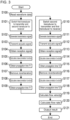
- the measurement performed by the propagation time measurement device 1 will be described with reference to the flowchart in FIG. 3 .
- step S100 the transmission signal generator 110 in the control circuit 102 reads the waveform data about a transmission signal from the storage 112.
- step S101 the control circuit 102 controls the switch 105 to connect the D/A converter 103 to the first transducer 101a and the A/D converter 104 to the second transducer 101b.
- the first transducer 101a thus serves as a transmitter, and the second transducer 101b as a receiver.
- step S102 the transmission signal generator 110 generates a transmission signal based on the waveform data read in step S100 and outputs the signal to the D/A converter 103.
- the transmission signal is temporarily stored in a RAM (work memory) for cross-correlation analysis performed later.
- step S103 the transmission signal resulting from D/A conversion and amplification performed by the D/A converter 103 is input into the first transducer 101a, which then transmits an acoustic signal based on the transmission signal.
- FIG. 4A is a diagram of an example transmission signal, with the horizontal axis representing time and the vertical axis representing the signal value.
- FIG. 4B is a diagram of an example acoustic signal based on the transmission signal in FIG. 4A , with the horizontal axis representing time and the vertical axis representing the sound pressure.
- the amplitude of the acoustic signal is not constant despite the constant amplitude of the transmission signal due to the frequency response of the transducer.
- the acoustic signal travels through the clamp 30, the pipe 120, and the fluid 121 to the second transducer 101b.
- step S104 the second transducer 101b converts the received acoustic signal to a reception signal and outputs the reception signal to the A/D converter 104.
- FIG. 4C is a diagram of an example reception signal, with the horizontal axis representing time and the vertical axis representing the signal value. In FIG. 4C , the vertical axis is enlarged relative to the vertical axis in FIG. 4A .
- the acoustic signal is attenuated through propagation.
- the reception signal has an amplitude (a voltage) on the order of about 1/100 to 1/1000 of the transmission signal.
- the transmission signal in FIG. 4A has an amplitude of about 30 V
- the reception signal resulting from A/D conversion performed by the A/D converter 104 enters the control circuit 102 and is temporarily stored into the RAM (work memory).
- step S105 the signal processor 111 reads the transmission signal and the reception signal from the RAM and calculates the cross-correlation function between the two signals.
- FIG. 4D is a diagram of an example cross-correlation function, showing an area near the maximum peak alone in an enlarged manner. The horizontal axis represents time (time shift), and the vertical axis represents the value of cross-correlation normalized to have the maximum peak height of 1.
- the cross-correlation function is a known technique, and is not described in detail herein.
- step S106 the signal processor 111 determines the temporal position of the maximum peak (vertex) in the cross-correlation function calculated in step S105 as a propagation time T1 of the acoustic signal from the first transducer 101a to the second transducer 101b.
- the propagation time T1 is affected by, for example, reverberation of the reception signal and deviates from the actual propagation time.
- the cross-correlation function calculated in step S105 is represented as discrete data.
- the points at which the cross-correlation function data is obtained may not match the peak (vertex) position.
- the signal processor 111 may thus approximate the shape of the waveform of the maximum peak and around the maximum peak (the waveform of the maximum peak) from the discrete data of the cross-correlation function and then estimate the position of the maximum peak.
- the signal processor 111 may transform the data near the maximum peak in the cross-correlation function to phase data by Hilbert transform.
- the resultant data may then be linearly approximated to use the zero crossing point (the position at which the phase is zero) on the approximate line as the position of the maximum peak.
- the signal processor 111 may estimate the shape of the waveform of the maximum peak by interpolating the data near the maximum peak in the cross-correlation function by polynomial approximation to determine the vertex position. Such processing allows determination of the position at which the cross-correlation is maximum, or more specifically, the propagation time of the acoustic signal, with a resolution higher than the sampling intervals of A/D conversion.
- step S107 the signal processor 111 removes, as reverberation, any signal component at and after the time point based on the propagation time T1 determined in step S106 from the reception signal read in step S105.
- the receiving transducer is expected to receive an acoustic signal with the same duration as the transmission signal after the propagation time elapses. Any signal component contained in the reception signal after the acoustic signal is received is expected to be reverberation. Thus, as shown in FIG.
- the signal processor 111 removes, from the reception signal, as reverberation, any signal component at and after the time point at which the total time of the propagation time T1 and a duration T0 of the transmission signal elapses from when the transmission signal is input into the first transducer 101a.
- the reverberation can thus be removed accurately.
- step S108 the signal processor 111 calculates the cross-correlation function between the transmission signal read in step S105 and the reception signal from which the reverberation has been removed in step S107.
- step S109 the signal processor 111 determines the temporal position of the maximum peak (vertex) in the cross-correlation function calculated in step S108 as a propagation time T1' of the acoustic signal from the first transducer 101a to the second transducer 101b. With the reverberation being removed from the reception signal, the propagation time T1' determined in this step is close to the actual propagation time.
- step S110 the control circuit 102 controls the switch 105 to connect the D/A converter 103 to the second transducer 101b and the A/D converter 104 to the first transducer 100a.
- the transmitting transducer is switched to the receiving transducer and the receiving transducer is to the transmitting transducer.
- the processing in subsequent steps 5111 to S118 is the same as the processing in steps S102 to S109 (except that the first transducer 101a is replaced with the second transducer 101b and the second transducer 101b with the first transducer 101a).
- a propagation time T2 of the acoustic signal from the second transducer 101b to the first transducer 101a is determined from the cross-correlation function based on the reception signal from which the reverberation has yet to be removed.
- a propagation time T2' of the acoustic signal from the second transducer 101b to the first transducer 101a is determined from the cross-correlation function based on the reception signal from which the reverberation has been removed.
- the processing described above determines the propagation time T1' of the acoustic signal from the first transducer 101a to the second transducer 101b and the propagation time T2' of the acoustic signal from the second transducer 101b to the first transducer 101a.
- a time difference occurs between the propagation time T1' and the propagation time T2' in accordance with the flow velocity of the fluid 121.
- the propagation time T1' and the propagation time T2' can be used to calculate the flow velocity and the flow rate of the fluid 121.
- the propagation time T1' and the propagation time T2' are accurately determined after the reverberation is removed, thus allowing the flow velocity and flow rate of the fluid 121 to be determined accurately as well.
- step S119 the signal processor 111 determines a flow velocity V of the fluid 121 with the formula below.
- V L 2 cos ⁇ 1 Tba ⁇ To ⁇ 1 Tab ⁇ To
- V is the flow velocity of the fluid
- L is the length of the propagation path in the pipe
- ⁇ is the propagation angle
- Tab is the propagation time T1' from the upstream transducer to the downstream transducer
- Tba is the propagation time T2' from the downstream transducer to the upstream transducer
- To is the propagation time for a non-fluid portion.
- the propagation time To for the non-fluid portion is, for example, the time for the acoustic signal to propagate through the clamp 30 and the pipe 120, and can be predetermined through experiment or simulation based on the specifications of the pipe 120 (e.g., the inner diameter, outer diameter, or material).
- step S120 the signal processor 111 determines a flow rate Q of the fluid with the formula below.
- Q V ⁇ A
- Q is the flow rate of the fluid
- V is the flow velocity of the fluid
- A is the hollow cross-section of the pipe.
- the hollow cross-section A is known in this example.
- step S121 the signal processor 111 outputs the processing results (e.g., the propagation time, the flow velocity, and the flow rate) to the output device 106.
- the processing results e.g., the propagation time, the flow velocity, and the flow rate
- the structure in the present embodiment described above allows the time point at which reverberation occurs to be determined accurately based on the propagation time determined using the reception signal from which the reverberation has yet to be removed.
- the structure then removes, as the reverberation, any signal component at and after the time point determined as above from the reception signal, and uses the resultant reception signal to redetermine the propagation time.
- the reverberation can thus be removed accurately, and the propagation time can be determined accurately.
- the structure can be used in highly-accurate measurement situations such as measuring a low flow rate.
- calculating the propagation time can avoid use of unintended signal values (signal values representing the reverberation). This reduces the processing time for calculating the propagation time and the power consumption used to calculate the propagation time.
- a propagation time measurement device 1 according to a second embodiment of the present invention removes reverberation with the second method described above.
- the basic structure is the same as in the first embodiment.
- the second embodiment will be described focusing on the difference from the first embodiment.
- FIG. 7 is a flowchart of measurement performed by the propagation time measurement device 1 according to the second embodiment.
- the same step numbers denote the same processing steps in the flowchart in the first embodiment ( FIG. 3 ).
- step S200 the signal processor 111 reads the reception signal from the RAM and approximates the envelope of the waveform of the reception signal, as shown in FIG. 8 .
- the envelope can be determined with a known technique and will not be described in detail.
- step S201 the signal processor 111 determines a value obtained by reducing the peak of the envelope determined in step S200 by a predetermined factor as a threshold and detects a time Ta taken for the signal value to converge to or below the determined threshold from the reception signal read in step S200.
- the predetermined factor is not limited, but is, for example, 1/2 times.
- step S202 the signal processor 111 removes, as reverberation, any signal component after the time Ta detected in step S201 from the reception signal read in step S200, as shown in FIG. 8 .
- step S203 the signal processor 111 reads the transmission signal from the RAM and calculates the cross-correlation function between the read transmission signal and the reception signal from which the reverberation has been removed in step S202.
- step S204 the signal processor 111 determines the temporal position of the maximum peak (vertex) in the cross-correlation function calculated in step S203 as the propagation time T1' of the acoustic signal from the first transducer 101a to the second transducer 101b. With the reverberation being removed from the reception signal, the propagation time T1' determined in this step is close to the actual propagation time.
- the processing in steps S110 to S113 is the same as in the first embodiment.
- the processing in steps S210 to S214 is the same as the processing in steps S200 to S204 (except that the first transducer 101a is replaced with the second transducer 101b and the second transducer 101b with the first transducer 100a).
- the signal processor 111 determines, as a threshold, a value obtained by reducing the peak of the envelope determined in step S210 by a predetermined factor and detects a time Tb taken for the signal value to converge to or below the determined threshold from the reception signal read in step S210.
- step S214 a propagation time T2' of the acoustic signal from the second transducer 101b to the first transducer 101a is determined from the cross-correlation function based on the reception signal from which the reverberation has been removed.
- the processing in steps S119 to S121 is the same as in the first embodiment.
- the structure according to the present embodiment described above determines, as a threshold, the envelope of the waveform of the reception signal from which the reverberation has yet to be removed and determines the value obtained by reducing the peak of the determined envelope by the predetermined factor.
- the structure then removes any signal component at and after the time point at which the signal value converges to or below the determined threshold as reverberation and uses the reception signal from which the reverberation has been removed to determine the propagation time.
- the reverberation can thus be removed accurately, and the propagation time can be determined accurately.
- the structure can be used in highly-accurate measurement situations such as measuring a low flow rate.
- calculating the propagation time can avoid use of unintended signal values (signal values representing the reverberation). This reduces the processing time for calculating the propagation time and the power consumption used to calculate the propagation time.
- a propagation time measurement device 1 according to a third embodiment of the present invention removes reverberation with the second method described above.
- the specific method for removing reverberation differs from the method in the second embodiment.
- the basic structure is the same as in the above embodiments.
- the third embodiment will be described focusing on the difference from the above embodiments.
- FIG. 9 is a flowchart of measurement performed by the propagation time measurement device 1 according to the third embodiment.
- the same step numbers denote the same processing steps in the flowchart in the second embodiment ( FIG. 7 ).
- the processing in steps S100 to S104 and step S200 is the same as in the second embodiment.
- the envelope data determined in step S200 is discrete data.
- the time intervals of the multiple discrete values included in the envelope are not limited, but are equivalent to the time intervals of the multiple peaks shown by the reception signal, or more specifically, identical to the time intervals of the multiple peaks shown by the transmission signal.
- step S301 the signal processor 111 determines, as a threshold, one of the multiple discrete values at a predetermined ordinal position from the greatest value included in the envelope determined in step S200.
- the signal processor 111 detects a time Ta taken for the signal value to converge to or below the determined threshold from the reception signal read in step S200.
- the predetermined ordinal position is not limited, but is, for example, the tenth position.
- step S302 the signal processor 111 removes, as reverberation, any signal component at and after the time Ta detected in step S301 from the reception signal read in step S200, as shown in FIG. 10 .
- step S303 the signal processor 111 reads the transmission signal from the RAM and calculates the cross-correlation function between the read transmission signal and the reception signal from which the reverberation has been removed in step S302.
- step S304 the signal processor 111 determines the temporal position of the maximum peak (vertex) in the cross-correlation function calculated in step S303 as a propagation time T1' of the acoustic signal from the first transducer 101a to the second transducer 101b. With the reverberation being removed from the reception signal, the propagation time T1' determined in this step is close to the actual propagation time.
- step S110 to S113 and step S210 is the same as in the second embodiment.
- the processing in steps S311 to S314 is the same as the processing in steps S301 to S304 (except that the first transducer 101a is replaced with the second transducer 101b and the second transducer 101b with the first transducer 100a).
- the signal processor 111 determines, as a threshold, one of the multiple discrete values at a predetermined ordinal position from the greatest value included in the envelope determined in step S210.
- the signal processor 111 detects a time Tb taken for the signal value to converge to or below the determined threshold from the reception signal read in step S210.
- step S314 a propagation time T2' of the acoustic signal from the second transducer 101b to the first transducer 101a is determined from the cross-correlation function based on the reception signal from which the reverberation has been removed.
- the processing in steps S119 to S121 is the same as in the second embodiment.
- the structure according to the present embodiment described above determines the envelope of the waveform of the reception signal from which the reverberation has yet to be removed and determines, as a threshold, one of the multiple discrete values at the predetermined ordinal position from the greatest value included in the determined envelope.
- the structure then removes any signal component at and after the time point at which the signal value converges to or below the determined threshold as reverberation and uses the reception signal from which the reverberation has been removed to determine the propagation time.
- the reverberation can thus be removed accurately, and the propagation time can be determined accurately.
- the structure can be used in highly-accurate measurement situations such as measuring a low flow rate. Additionally, calculating the propagation time can avoid use of unintended signal values (signal values representing the reverberation). This reduces the processing time for calculating the propagation time and the power consumption used to calculate the propagation time.
- a propagation time measurement device 1 according to a fourth embodiment of the present invention removes reverberation with the third method described above.
- the basic structure is the same as in the above embodiments.
- the fourth embodiment will be described focusing on the difference from the above embodiments.
- FIG. 11 is a flowchart of measurement performed by the propagation time measurement device 1 according to the fourth embodiment.
- the same step numbers denote the same processing steps in the flowchart in the first embodiment ( FIG. 3 ).
- step S400 the signal processor 111 reads the reception signal from the RAM and determines, as a threshold, one of the multiple peaks at the predetermined ordinal position from the highest peak shown by the reception signal. The signal processor 111 then detects a time Ta taken for the signal value to converge to or below the determined threshold from the reception signal.
- the predetermined ordinal position is not limited, but is, for example, the tenth position.
- step S401 the signal processor 111 removes, as reverberation, any signal component at and after the time Ta detected in step S400 from the reception signal read in step S400, as shown in FIG. 12 .
- step S402 the signal processor 111 reads the transmission signal from the RAM and calculates the cross-correlation function between the read transmission signal and the reception signal from which the reverberation has been removed in step S401.
- step S403 the signal processor 111 determines the temporal position of the maximum peak (vertex) in the cross-correlation function calculated in step S402 as a propagation time T1' of the acoustic signal from the first transducer 101a to the second transducer 101b. With the reverberation being removed from the reception signal, the propagation time T1' determined in this step is close to the actual propagation time.
- the processing in steps S110 to S113 is the same as in the first embodiment.
- the processing in steps S410 to S413 is the same as the processing in steps S400 to S403 (except that the first transducer 101a is replaced with the second transducer 101b and the second transducer 101b with the first transducer 100a).
- the signal processor 111 reads the reception signal (the reception signal obtained in step S113) from the RAM and determines, as a threshold, one of the multiple peaks at the predetermined ordinal position from the highest peak shown by the reception signal. The signal processor 111 then detects a time Tb taken for the signal value to converge to or below the threshold from the reception signal.
- step S413 a propagation time T2' of the acoustic signal from the second transducer 101b to the first transducer 101a is determined from the cross-correlation function based on the reception signal from which the reverberation has been removed.
- the processing in steps S119 to S121 is the same as in the first embodiment.
- the structure according to the present embodiment described above determines, as a threshold, one of the multiple peaks at the predetermined ordinal position from the highest peak shown by the reception signal from which the reverberation has yet to be removed.
- the structure then removes any signal component at and after the time point at which the signal value converges to or below the determined threshold as reverberation and uses the reception signal from which the reverberation has been removed to determine the propagation time.
- the reverberation can thus be removed accurately, and the propagation time can be determined accurately.
- the structure can be used in highly-accurate measurement situations such as measuring a low flow rate. Additionally, calculating the propagation time can avoid use of unintended signal values (signal values representing the reverberation).
- a reception signal sampled at certain periods (resolutions) may not include any peak that is to occur in the reception signals.
- the structures in the first to third embodiments may be expected to determine the propagation time more accurately, the structures involve more processes such as determining a tentative propagation time or determining the envelope.
- the embodiments described above are mere examples of the present invention.
- the present invention is not limited to the specific embodiments described above, but may be modified variously within the scope of the technical ideas of the invention.
- the measured propagation time is used to calculate the flow velocity and the flow rate of the fluid.
- the flow velocity and the flow rate are not calculated.
- the propagation time measurement device may simply measure the propagation time (at least one of the propagation time T1' or the propagation time T2').
- the propagation angle ⁇ may be 90 degrees for simply measuring the propagation time.
- the clamp-on device to clamp the pipe is used.
- the device may be incorporated in the pipe.
- the transducers may be three or more transducers, including transducer pairs for propagating acoustic signals downstream and transducer pairs for propagating acoustic signals upstream.
- the transmitting transducer and the receiving transducer may be at any different positions with respect to the pipe, rather than being opposite to each other across the pipe or at different positions in the longitudinal direction of the pipe.
- the storage 112 may prestore information about the time point at which reverberation occurs, and the signal processor 111 may remove the reverberation based on the information stored in the storage 112.
- the information about the time point at which reverberation occurs may or may not simply indicate the time point (e.g., the time T1 + the time T0 or the time T2 + the time T0 in the first embodiment or the time Ta or the time Tb in the second to fourth embodiments).
- the information about the time point at which reverberation occurs may indicate the propagation time (the propagation time T1 or the propagation time T2 in the first embodiment) determined using the reception signal containing reverberation.
- the information about the time point at which reverberation occurs may indicate a threshold (the thresholds used in the second to fourth embodiments) based on the envelope or multiple peaks.
- the information about the time point at which reverberation occurs is obtained in the same manner as described in the first to fourth embodiments in, for example, premeasurement.
- the signal processor 111 instead of determining the information about the time point at which reverberation occurs, the signal processor 111 reads the same information from the storage 112. For example, to obtain the propagation time T1' with the method in the first embodiment, the processing in steps S101 to S106 in FIG. 3 is performed in the premeasurement. The signal processor 111 then stores the determined propagation time T1 into the storage 112. In measurement, the processing in steps S101 to S104 is performed, and the signal processor 111 reads the propagation time T1 from the storage 112 and performs the processing in steps S107 to S109.
- the pair of transducers may transmit and receive the acoustic signal multiple times in measurement of the propagation time T1' or the propagation time T2'.
- the signal processor 111 may then use the multiple reception signals resulting from the multiple transmission and reception operations to obtain information about the time point at which reverberation occurs.
- the combination of multiple reception signals can apparently increase the resolution, and thus the use of multiple reception signals allows the time point at which the reverberation occurs to be determined more accurately. For example, the propagation time T1, the propagation time T2, the envelope, and the peaks of the reception signal can be determined more accurately. This thus allows the reverberation to be removed more accurately and the propagation time to be determined more accurately.
- the time Ta for removing the reverberation from the reception signal obtained by the second transducer 101b (corresponding to the acoustic signal from the first transducer 101a to the second transducer 101b) and the time Tb for removing the reverberation from the reception signal obtained by the first transducer 101a (corresponding to the acoustic signal from the second transducer 101b to the first transducer 101a) are determined separately.
- the manner of determining the times Ta and Tb is not limited to this example. For example, one of the time Ta or the time Tb may be detected, and the detected time may also be used as the other of the time Ta or the time Tb. This reduces the processing load and the processing time.
- the time Ta alone is detected, and the time Ta is used as the time Tb.
- one of the propagation time T1 or the propagation time T2 may also be used as the other of the propagation time T1 or the propagation time T2.
- one of the two thresholds for determining the two times Ta and Tb may also be used as the other of the two thresholds. This can also reduce the processing load and the processing time.
- a propagation time measurement device (1) comprising:
- a propagation time measurement device (1) comprising:
- a propagation time measurement device (1) comprising:
Landscapes
- Physics & Mathematics (AREA)
- Electromagnetism (AREA)
- Fluid Mechanics (AREA)
- General Physics & Mathematics (AREA)
- Measuring Volume Flow (AREA)
- Measurement Of Velocity Or Position Using Acoustic Or Ultrasonic Waves (AREA)
Abstract
Description
- The present invention relates to a technique for measuring the propagation time of an acoustic signal.
- Known devices in practical use measure the propagation time of an acoustic signal propagating inside a pipe with a sensor externally mounted on the pipe. The devices nondestructively measure the flow velocity and the flow rate of a fluid flowing in the pipe based on the propagation time. Such a device typically uses ultrasound as an acoustic signal, and is referred to as, for example, an ultrasonic flowmeter.
- For example,
Patent Literature 1 describes a device that uses a pair of upstream and downstream ultrasonic transducers on a pipe to determine the flow rate of a fluid based on the difference in a propagation time between ultrasound propagating in the flow direction of the fluid and ultrasound propagating in the direction opposite to the flow direction. The device inPatent Literature 1 calculates, as the propagation time difference, the cross-correlation between the signal received by the upstream ultrasonic transducer and the signal received by the downstream ultrasonic transducer. - Patent Literature 1:
Japanese Unexamined Patent Application Publication No. 2017-187310 - However, transducers that receive acoustic signals such as ultrasound cannot stop immediately after they stop receiving acoustic signals, and output electric signals (reception signals) containing reverberation. Any reverberation contained in a reception signal can be noise that affects accurate determination of the propagation time and undermine accurate determination of the flow velocity and the flow rate of the fluid flowing through the pipe.
- In response to the above issue, one or more aspects of the present invention are directed to a technique for determining a propagation time accurately.
- The technique according to one or more aspects of the present invention has the structure below.
- A propagation time measurement device according to a first aspect of the present invention includes a plurality of transducers and a signal processor. The plurality of transducers are at different positions with respect to a pipe through which a fluid flows. The plurality of transducers include a first transducer that converts a transmission signal as an electrical signal to an acoustic signal and a second transducer that receives the acoustic signal transmitted from the first transducer through the fluid in the pipe and converts the received acoustic signal to a reception signal as an electrical signal. The signal processor removes reverberation from the reception signal and determines a propagation time of the acoustic signal from the first transducer to the second transducer by cross-correlation analysis between the transmission signal and the reception signal from which the reverberation has been removed. The signal processor determines a propagation time of the acoustic signal from the first transducer to the second transducer by cross-correlation analysis between the transmission signal and the reception signal from which the reverberation has yet to be removed, removes, as the reverberation, a signal component at and after a time point based on the determined propagation time, and redetermines the propagation time of the acoustic signal from the first transducer to the second transducer by cross-correlation analysis between the transmission signal and the reception signal from which the reverberation has been removed.
- The reverberation contained in the reception signal affects determination of the propagation time. The time point at which the reverberation occurs can thus be determined accurately based on the propagation time determined using the reception signal from which the reverberation has yet to be removed. The above structure removes, as reverberation, any signal component at and after the time point determined as above from the reception signal and uses the reception signal from which the reverberation has been removed to redetermine the propagation time. The reverberation can thus be removed accurately, and the propagation time can be determined accurately. Additionally, calculating the propagation time can avoid use of unintended signal values (signal values representing the reverberation). This reduces the processing time for calculating the propagation time and the power consumption used to calculate the propagation time.
- The receiving transducer is expected to receive an acoustic signal with the same duration as the transmission signal after the propagation time elapses. In the reception signal, any signal component after the acoustic signal is received serves as reverberation. In the first aspect, the time point may be a time point at which a total time of the propagation time determined by the cross-correlation analysis between the transmission signal and the reception signal from which the reverberation has yet to be removed and a duration of the transmission signal elapses from when the transmission signal is input into the first transducer. The reverberation can be removed more accurately to allow the propagation time to be determined more accurately.
- A propagation time measurement device according to a second aspect of the present invention includes a plurality of transducers and a signal processor. The plurality of transducers are at different positions with respect to a pipe through which a fluid flows. The plurality of transducers include a first transducer that converts a transmission signal as an electrical signal to an acoustic signal and a second transducer that receives the acoustic signal transmitted from the first transducer through the fluid in the pipe and converts the received acoustic signal to a reception signal as an electrical signal. The signal processor removes reverberation from the reception signal and determines a propagation time of the acoustic signal from the first transducer to the second transducer by cross-correlation analysis between the transmission signal and the reception signal from which the reverberation has been removed. The signal processor approximates an envelope of a waveform of the reception signal from which the reverberation has yet to be removed, determines a threshold based on the envelope, and removes, as the reverberation, a signal component at and after a time point at which a signal value of the reception signal converges to or below the determined threshold.
- The waveform of the reception signal defines an envelope with a relatively high value, whereas the reverberation has a relatively low signal value. The time point at which the reverberation occurs can thus be determined accurately based on the envelope. The above structure approximates the envelope from the reception signal and removes, from the reception signal, as reverberation, any signal component at and after the time point at which the signal value converges to or below a threshold based on the envelope. The reception signal from which the reverberation has been removed is then used to determine the propagation time. The reverberation can thus be removed accurately, and the propagation time can be determined accurately. Additionally, calculating the propagation time can avoid use of unintended signal values (signal values representing the reverberation). This reduces the processing time for calculating the propagation time and the power consumption used to calculate the propagation time.
- In the second aspect, the signal processor may determine a value obtained by reducing a peak of the envelope by a predetermined factor as the threshold. In the second aspect, the signal processor may determine, as the threshold, one of a plurality of discrete values at a predetermined ordinal position from a greatest discrete value included in the envelope.
- A propagation time measurement device according to a third aspect of the present invention includes a plurality of transducers and a signal processor. The plurality of transducers are at different positions with respect to a pipe through which a fluid flows. The plurality of transducers include a first transducer that converts a transmission signal as an electrical signal to an acoustic signal and a second transducer that receives the acoustic signal transmitted from the first transducer through the fluid in the pipe and converts the received acoustic signal to a reception signal as an electrical signal. The signal processor removes reverberation from the reception signal and determines a propagation time of the acoustic signal from the first transducer to the second transducer by cross-correlation analysis between the transmission signal and the reception signal from which the reverberation has been removed. The signal processor removes, as the reverberation, a signal component at and after a time point at which a signal value of the reception signal converges to or below a peak at a predetermined ordinal position from a highest peak of a plurality of peaks shown by the reception signal from which the reverberation has yet to be removed.
- The reception signal shows multiple peaks that gradually increase and then gradually decrease. The reverberation has a relatively low signal value. The time point at which the reverberation occurs can thus be determined accurately based on the multiple peaks. The above structure uses one of the multiple peaks at the predetermined ordinal position from the highest peak to remove, from the reception signal, as reverberation, any signal component at and after the time point at which the signal value converges to or below the threshold, and determines the propagation time using the reception signal from which the reverberation has been removed. The reverberation can thus be removed accurately, and the propagation time can be determined accurately. Additionally, calculating the propagation time can avoid use of unintended signal values (signal values representing the reverberation). This reduces the processing time for calculating the propagation time and the power consumption used to calculate the propagation time.
- The structure in each of the first, second, and third aspects may further include a storage that prestores information about the time point. The signal processor may remove the reverberation based on the information prestored in the storage. The information about the time point may or may not simply indicate the time point. For example, the information about the time point may indicate the propagation time determined using the reception signal from which the reverberation has yet to be removed or indicate the threshold based on the envelope or the multiple peaks.
- In each of the first, second, and third aspects, the signal processor may obtain information about the time point using a plurality of reception signals resulting from a plurality of transmission operations from the first transducer and resulting from a plurality of reception operations at the second transducer. This allows the time point at which the reverberation occurs to be determined more accurately. This thus allows the reverberation to be removed more accurately and the propagation time to be determined more accurately.
- In each of the first, second, and third aspects, the first transducer and the second transducer may be opposite to each other across the pipe. In each of the first, second, and third aspects, the first transducer and the second transducer may be at different positions in a longitudinal direction of the pipe.
- The structure in each of the first, second, and third aspects may further include a switch that performs switching to cause the second transducer to receive an input of the transmission signal and transmit an acoustic signal and to cause the first transducer to receive the acoustic signal transmitted from the second transducer and output the reception signal. The signal processor may further remove reverberation from the reception signal output from the first transducer, and determine a propagation time of the acoustic signal from the second transducer to the first transducer by cross-correlation analysis between the transmission signal input into the second transducer and the reception signal output from the first transducer and from which the reverberation has been removed. This allows accurate determination of the propagation time of the acoustic signal propagating downstream and the propagation time of the acoustic signal propagating upstream for the same propagation path.
- The signal processor may determine at least one of a flow velocity or a flow rate of the fluid in the pipe based on a difference between the propagation time of the acoustic signal from the first transducer to the second transducer and the propagation time of the acoustic signal from the second transducer to the first transducer. This allows information about the fluid in the pipe to be determined highly accurately.
- One or more aspects of the present invention may be directed to a propagation time measurement device including at least one of the above components or to, for example, a flow velocity measurement device, a flow rate measurement device, a flowmeter, or a flow sensor. One or more aspects of the present invention may be directed to a propagation time measurement method, a flow velocity measurement method, or a flow rate measurement method including at least one of the above processes. One or more aspects of the present invention may be directed to a program for implementing any of these methods or to a non-transitory storage medium storing the program. The present invention may be implemented by combining the above components and processes in any possible manner.
- The technique according to the above aspects of the present invention allows a propagation time to be determined accurately.
-
- [
FIG. 1] FIG. 1 is a schematic diagram of a propagation time measurement device. - [
FIG. 2] FIG. 2 is a cross-sectional view of example transducers mounted on a pipe. - [
FIG. 3] FIG. 3 is a flowchart of measurement performed by a propagation time measurement device according to a first embodiment. - [
FIG. 4] FIG. 4A is a diagram of an example transmission signal,FIG. 4B is a diagram of an example acoustic signal based on the transmission signal inFIG. 4A , -
FIG. 4C is a diagram of an example reception signal, andFIG. 4D is a diagram of an example cross-correlation function. - [
FIG. 5] FIG. 5A is a diagram of an example cross-correlation function, andFIG. 5B is a diagram of an example of Hilbert transform. - [
FIG. 6] FIG. 6 is a diagram describing removal of reverberation in the first embodiment. - [
FIG. 7] FIG. 7 is a flowchart of measurement performed by a propagation time measurement device according to a second embodiment. - [
FIG. 8] FIG. 8 is diagram describing removal of reverberation in the second embodiment. - [
FIG. 9] FIG. 9 is a flowchart of measurement performed by a propagation time measurement device according to a third embodiment. - [
FIG. 10] FIG. 10 is a diagram describing removal of reverberation in the third embodiment. - [
FIG. 11] FIG. 11 is a flowchart of measurement performed by a propagation time measurement device according to a fourth embodiment. - [
FIG. 12] FIG. 12 is a diagram describing removal of reverberation in the fourth embodiment. - An example use of a propagation time measurement device will be described with reference to
FIG. 1 . - A propagation
time measurement device 1 includes two ormore transducers 101 to receive an acoustic signal transmitted from one transducer (e.g., atransducer 101a) with another transducer (e.g., atransducer 101b) and determine the time (propagation time) taken for the acoustic signal to propagate on a path between the two transducers. Thetransducers 101 are at different positions with respect to apipe 120. The acoustic signal propagating between the twotransducers 101 thus travels through (crosses) thepipe 120. The propagation time of the acoustic signal is not constant but varies in accordance with the state (e.g., flow velocity, flow rate, or any bubbles or foreign matter) of a fluid 121 flowing in thepipe 120. Thus, the propagation time measured by the propagationtime measurement device 1 can be used to measure the state of the fluid 121 in thepipe 120 nondestructively. - The fluid 121 can be any substance that can transmit acoustic signals, including a liquid or a gas. Acoustic signals are typically ultrasonic but may include audible sound waves.
- The propagation
time measurement device 1 uses cross-correlation analysis to calculate the propagation time. For example, a transmission signal is an electric signal for driving a transmittingtransducer 101, and a reception signal is an electric signal output from a receivingtransducer 101. The propagationtime measurement device 1 calculates the cross-correlation function between the transmission signal and the reception signal. The propagationtime measurement device 1 then determines the lag (time delay) of the reception signal to the transmission signal based on the position of the maximum peak in the cross-correlation function. This lag corresponds to the propagation time of the acoustic signal from the transmittingtransducer 101 to the receivingtransducer 101. - When the signal waveform of the transmission signal is retained sufficiently in the reception signal, a distinctive peak occurs in the cross-correlation function. Thus, the lag (or propagation time) between the two signals can be determined accurately. However, the receiving
transducer 101 cannot stop immediately after stopping receiving an acoustic signal. The reception signal thus contains reverberation. Any reverberation contained in the reception signal can be noise that can cause, for example, peaks to occur at temporal positions different from the actual propagation time in the cross-correlation function and can undermine accurate determination of the propagation time. Thus, the flow velocity and the flow rate of the fluid 121 flowing in thepipe 120 cannot be determined accurately. Flowmeters that can measure low flow rates are now awaited to measure the propagation time with the accuracy of, for example, nanosecond order to picosecond order. - The propagation
time measurement device 1 removes the reverberation from the reception signal and uses the resultant reception signal to determine the propagation time. More specifically, the propagationtime measurement device 1 removes the reverberation with one of the first to third methods described below. Removing the reverberation is any process that excludes the signal value representing the reverberation from cross-correlation analysis (from calculation of the cross-correlation function). For example, the removal process may include setting (cutting) the signal value corresponding to the reverberation to zero or distinguishing the signal value representing the reverberation from other signal values. - With the first method, the propagation
time measurement device 1 determines the propagation time by analyzing the cross-correlation between the transmission signal and the reception signal from which the reverberation has yet to be removed, and removes, as reverberation, any signal component at and after the time point based on the determined propagation time. The propagationtime measurement device 1 then redetermines the propagation time by analyzing the cross-correlation between the transmission signal and the reception signal from which the reverberation has been removed. - The reverberation contained in the reception signal affects determination of the propagation time. The time point at which the reverberation occurs can thus be determined accurately based on the propagation time determined using the reception signal from which the reverberation has yet to be removed. The first method removes, as reverberation, any signal component at and after the time point determined as above from the reception signal and uses the reception signal from which the reverberation has been removed to redetermine the propagation time. This allows the reverberation to be removed accurately, the correct peak (peak at a position corresponding to the actual propagation time) to be detected accurately from the cross-correlation function, and the propagation time to be determined accurately.
- With the second method, the propagation
time measurement device 1 approximates, from the reception signal from which the reverberation has yet to be removed, the envelope of the waveform of the reception signal, determines a threshold based on the approximated envelope, and removes, as reverberation, any signal component at and after the time point at which the signal value converges to or below the determined threshold. - The waveform of the reception signal defines an envelope with a relatively high value, whereas the reverberation has a relatively low signal value. The time point at which the reverberation occurs can thus be determined accurately based on the envelope. With the second method, the envelope is approximated from the reception signal, and any signal component at and after the time point at which the signal value converges to or below the threshold based on the envelope is removed from the reception signal as reverberation. The reception signal from which the reverberation has been removed is then used to determine the propagation time. This allows the reverberation to be removed accurately, the correct peak to be detected accurately from the cross-correlation function, and the propagation time to be determined accurately.
- With the third method, the propagation
time measurement device 1 removes, as reverberation, any signal component at and after the time point at which the signal value converges to or below the peak at a predetermined ordinal position from the highest peak of the multiple peaks shown by the reception signal from which the reverberation has yet to be removed. - The reception signal shows multiple peaks that gradually increase and then gradually decrease. The reverberation has a relatively low signal value. The time point at which the reverberation occurs can thus be determined accurately based on the multiple peaks. The third method uses one of the multiple peaks at the predetermined ordinal position from the highest peak as a threshold to remove, as reverberation, any signal component at and after the time point at which the signal value converges to or below the threshold from the reception signal and determines the propagation time using the reception signal from which the reverberation has been removed. This allows the reverberation to be removed accurately, the correct peak to be detected accurately from the cross-correlation function, and the propagation time to be determined accurately.
- With any of the first to third methods, calculating the propagation time (specifically, calculating the cross-correlation function) can avoid use of unintended signal values (signal values representing the reverberation). This reduces the processing time for calculating the propagation time and the power consumption used to calculate the propagation time.
- The specific structure of the propagation
time measurement device 1 will be described with reference toFIGs. 1 and2 .FIG. 1 is schematic block diagram of the propagationtime measurement device 1.FIG. 2 is a cross-sectional view of example transducers mounted on a pipe. The propagationtime measurement device 1 according to the present embodiment nondestructively measures the flow velocity and the flow rate of the fluid 121 flowing in thepipe 120. The device is also referred to as an ultrasonic flowmeter or an ultrasonic flow sensor. - The propagation
time measurement device 1 includes amain body 100 and themultiple transducers 101. Themain body 100 and eachtransducer 101 are connected with a cable. In the present embodiment, the structure includes twotransducers 101, or more specifically, afirst transducer 101a upstream in the longitudinal direction of thepipe 120 and asecond transducer 101b downstream from thefirst transducer 101a. The two transducers are hereafter referred to as thefirst transducer 101a and thesecond transducer 101b when distinguished from each other and simply astransducers 101 or atransducer 101 when described commonly. The structure may include three ormore transducers 101, rather than twotransducers 101. - The
transducers 101 convert an electrical signal to an acoustic signal and an acoustic signal to an electric signal. Thetransducers 101 may also be referred to as transducers. For example, thetransducers 101 may be, for example, piezoelectric elements that use the piezoelectric effect to convert a force to a voltage and a voltage to a force. As shown inFIG. 2 , eachtransducer 101 is buried in aresin clamp 30. With theclamp 30 holding thepipe 120, the twotransducers pipe 120. The line segment connecting the twotransducers pipe 120. This clamp structure facilitates mounting of thetransducers 101 onto the existingpipe 120 at appropriate positions (without any modification to the pipe 120). Any grease or gel applied between thepipe 120 and theclamp 30 can tightly connect thepipe 120 and theclamp 30 together and increase the acoustic impedance matching between them. The angle θ is the propagation angle of the acoustic signal. The propagation angle θ may be 0 < θ < 90 degrees, or more specifically, 20 < θ < 60 degrees to use transit-time described below, although the angle may be set to any angle. - The
main body 100 mainly includes acontrol circuit 102, a digital-to-analog (D/A)converter 103, an analog-to-digital (A/D)converter 104, aswitch 105, and anoutput device 106. Thecontrol circuit 102 controls the components of the propagationtime measurement device 1 and performs, for example, signal processing and computations. The D/A converter 103 performs D/A conversion and signal amplification based on a transmission signal (digital data) input from thecontrol circuit 102 and outputs the resulting transmission signal (analog signal) at a predetermined voltage to one of thetransducers 101. The A/D converter 104 converts a reception signal (analog signal) input from anothertransducer 101 to digital data at predetermined sampling intervals and outputs the resulting reception signal (digital data) to thecontrol circuit 102. Theswitch 105 switches the connection of the D/A converter 103 and the A/D converter 104 with thefirst transducer 101a and thesecond transducer 101b. Thetransducer 101 connected to the D/A converter 103 serves as a transmitter. Thetransducer 101 connected to the A/D converter 104 serves as a receiver. Theoutput device 106 outputs information such as the results of signal processing and computations performed by thecontrol circuit 102. For example, theoutput device 106 is a display. Themain body 100 may also include an input device (e.g., buttons or a touch panel) for user operations and a communication circuit (e.g., Wi-Fi module) to transmit information to an external device (e.g., an external computer or a server). - As shown in
FIG. 1 , thecontrol circuit 102 includes atransmission signal generator 110, asignal processor 111, and astorage 112. Thetransmission signal generator 110 generates transmission signal data for measurement and outputs the data to the D/A converter 103. Thesignal processor 111 calculates the propagation time of the acoustic signal based on the transmission signal and the reception signal and also calculates the flow velocity, the flow rate, or both of the fluid based on the propagation time. Thesignal processor 111 also removes reverberation from the reception signal. In the present embodiment, thesignal processor 111 removes reverberation using the first method described above. Thestorage 112 stores waveform data that defines the waveform of the transmission signal. Thetransmission signal generator 110 reads the waveform data from thestorage 112 and generates transmission signal data. - The
control circuit 102 is, for example, a computer including a central processing unit (CPU), a random-access memory (RAM), a nonvolatile storage (e.g., read-only memory or ROM, a flash memory, or a hard disk drive), and an input-output (I/O) device. In this case, the CPU loads the program stored in the storage into the RAM and executes the program to implement thetransmission signal generator 110 and thesignal processor 111. Any computer may be used. For example, the computer may be a personal computer, an embedded computer, a smartphone, or a tablet. In some embodiments, all or part of the functions provided by thecontrol circuit 102 may be implemented by a circuit such as an application-specific integrated circuit (ASIC) or a field-programmable gate array (FPGA). In some embodiments, distributed computing and cloud computing may allow thecontrol circuit 102 to work together with other computers to perform the processing described later. - The
pipe 120 may be formed from any material, and have any size and any shape. For example, thepipe 120 may be a metal pipe or a resin pipe. Thepipe 120 may be sized in accordance with the standard defined by Japanese Industrial Standards (JIS) or the American National Standards Institute (ANSI), or sized individually. The method in the present embodiment allows highly accurate measurement of low flow rates, and thus is particularly effective in measuring small pipes, such as 1/8-inch pipes (OD: 3.18 mm, ID: 1.59 mm), 1/4-inch pipes (OD: 6.35 mm, ID: 3.97 mm), and 1/2-inch pipes (OD: 12.70 mm, ID: 9.53 mm). The pipe may be bent or curved, rather than straight, and may have any cross section. - The measurement performed by the propagation
time measurement device 1 will be described with reference to the flowchart inFIG. 3 . - In step S100, the
transmission signal generator 110 in thecontrol circuit 102 reads the waveform data about a transmission signal from thestorage 112. - In step S101, the
control circuit 102 controls theswitch 105 to connect the D/A converter 103 to thefirst transducer 101a and the A/D converter 104 to thesecond transducer 101b. Thefirst transducer 101a thus serves as a transmitter, and thesecond transducer 101b as a receiver. - In step S102, the
transmission signal generator 110 generates a transmission signal based on the waveform data read in step S100 and outputs the signal to the D/A converter 103. The transmission signal is temporarily stored in a RAM (work memory) for cross-correlation analysis performed later. - In step S103, the transmission signal resulting from D/A conversion and amplification performed by the D/
A converter 103 is input into thefirst transducer 101a, which then transmits an acoustic signal based on the transmission signal.FIG. 4A is a diagram of an example transmission signal, with the horizontal axis representing time and the vertical axis representing the signal value.FIG. 4B is a diagram of an example acoustic signal based on the transmission signal inFIG. 4A , with the horizontal axis representing time and the vertical axis representing the sound pressure. In this example, the amplitude of the acoustic signal is not constant despite the constant amplitude of the transmission signal due to the frequency response of the transducer. The acoustic signal travels through theclamp 30, thepipe 120, and the fluid 121 to thesecond transducer 101b. - In step S104, the
second transducer 101b converts the received acoustic signal to a reception signal and outputs the reception signal to the A/D converter 104.FIG. 4C is a diagram of an example reception signal, with the horizontal axis representing time and the vertical axis representing the signal value. InFIG. 4C , the vertical axis is enlarged relative to the vertical axis inFIG. 4A . The acoustic signal is attenuated through propagation. Thus, the reception signal has an amplitude (a voltage) on the order of about 1/100 to 1/1000 of the transmission signal. For example, the transmission signal inFIG. 4A has an amplitude of about 30 V, whereas the reception signal inFIG. 4C has an amplitude of about 10 mV. Additionally, various noise components including reverberation are contained in the reception signal, as shown inFIG. 4C . The reception signal resulting from A/D conversion performed by the A/D converter 104 enters thecontrol circuit 102 and is temporarily stored into the RAM (work memory). - In step S105, the
signal processor 111 reads the transmission signal and the reception signal from the RAM and calculates the cross-correlation function between the two signals.FIG. 4D is a diagram of an example cross-correlation function, showing an area near the maximum peak alone in an enlarged manner. The horizontal axis represents time (time shift), and the vertical axis represents the value of cross-correlation normalized to have the maximum peak height of 1. The cross-correlation function is a known technique, and is not described in detail herein. - In step S106, the
signal processor 111 determines the temporal position of the maximum peak (vertex) in the cross-correlation function calculated in step S105 as a propagation time T1 of the acoustic signal from thefirst transducer 101a to thesecond transducer 101b. The propagation time T1 is affected by, for example, reverberation of the reception signal and deviates from the actual propagation time. - Due to the limitation on digital signal processing, the cross-correlation function calculated in step S105 is represented as discrete data. Thus, as in
FIG. 5A , the points at which the cross-correlation function data is obtained (the points indicated by solid circles) may not match the peak (vertex) position. In step S106, thesignal processor 111 may thus approximate the shape of the waveform of the maximum peak and around the maximum peak (the waveform of the maximum peak) from the discrete data of the cross-correlation function and then estimate the position of the maximum peak. For example, as shown inFIG. 5B , thesignal processor 111 may transform the data near the maximum peak in the cross-correlation function to phase data by Hilbert transform. The resultant data may then be linearly approximated to use the zero crossing point (the position at which the phase is zero) on the approximate line as the position of the maximum peak. In some embodiments, thesignal processor 111 may estimate the shape of the waveform of the maximum peak by interpolating the data near the maximum peak in the cross-correlation function by polynomial approximation to determine the vertex position. Such processing allows determination of the position at which the cross-correlation is maximum, or more specifically, the propagation time of the acoustic signal, with a resolution higher than the sampling intervals of A/D conversion. - In step S107, the
signal processor 111 removes, as reverberation, any signal component at and after the time point based on the propagation time T1 determined in step S106 from the reception signal read in step S105. The receiving transducer is expected to receive an acoustic signal with the same duration as the transmission signal after the propagation time elapses. Any signal component contained in the reception signal after the acoustic signal is received is expected to be reverberation. Thus, as shown inFIG. 6 , thesignal processor 111 removes, from the reception signal, as reverberation, any signal component at and after the time point at which the total time of the propagation time T1 and a duration T0 of the transmission signal elapses from when the transmission signal is input into thefirst transducer 101a. The reverberation can thus be removed accurately. - In step S108, the
signal processor 111 calculates the cross-correlation function between the transmission signal read in step S105 and the reception signal from which the reverberation has been removed in step S107. - In step S109, the
signal processor 111 determines the temporal position of the maximum peak (vertex) in the cross-correlation function calculated in step S108 as a propagation time T1' of the acoustic signal from thefirst transducer 101a to thesecond transducer 101b. With the reverberation being removed from the reception signal, the propagation time T1' determined in this step is close to the actual propagation time. - In step S110, the
control circuit 102 controls theswitch 105 to connect the D/A converter 103 to thesecond transducer 101b and the A/D converter 104 to the first transducer 100a. In other words, the transmitting transducer is switched to the receiving transducer and the receiving transducer is to the transmitting transducer. The processing in subsequent steps 5111 to S118 is the same as the processing in steps S102 to S109 (except that thefirst transducer 101a is replaced with thesecond transducer 101b and thesecond transducer 101b with thefirst transducer 101a). In step S115, a propagation time T2 of the acoustic signal from thesecond transducer 101b to thefirst transducer 101a is determined from the cross-correlation function based on the reception signal from which the reverberation has yet to be removed. In step S118, a propagation time T2' of the acoustic signal from thesecond transducer 101b to thefirst transducer 101a is determined from the cross-correlation function based on the reception signal from which the reverberation has been removed. - The processing described above determines the propagation time T1' of the acoustic signal from the
first transducer 101a to thesecond transducer 101b and the propagation time T2' of the acoustic signal from thesecond transducer 101b to thefirst transducer 101a. When the fluid 121 flows in thepipe 120, a time difference occurs between the propagation time T1' and the propagation time T2' in accordance with the flow velocity of thefluid 121. Thus, the propagation time T1' and the propagation time T2' can be used to calculate the flow velocity and the flow rate of thefluid 121. The propagation time T1' and the propagation time T2' are accurately determined after the reverberation is removed, thus allowing the flow velocity and flow rate of the fluid 121 to be determined accurately as well. - In step S119, the
signal processor 111 determines a flow velocity V of the fluid 121 with the formula below.
- In the formula, V is the flow velocity of the fluid, L is the length of the propagation path in the pipe, θ is the propagation angle, Tab is the propagation time T1' from the upstream transducer to the downstream transducer, Tba is the propagation time T2' from the downstream transducer to the upstream transducer, and To is the propagation time for a non-fluid portion. The propagation time To for the non-fluid portion is, for example, the time for the acoustic signal to propagate through the
clamp 30 and thepipe 120, and can be predetermined through experiment or simulation based on the specifications of the pipe 120 (e.g., the inner diameter, outer diameter, or material). - In step S120, the
signal processor 111 determines a flow rate Q of the fluid with the formula below.
- In the formula, Q is the flow rate of the fluid, V is the flow velocity of the fluid, and A is the hollow cross-section of the pipe. The hollow cross-section A is known in this example.
- In step S121, the
signal processor 111 outputs the processing results (e.g., the propagation time, the flow velocity, and the flow rate) to theoutput device 106. - The structure in the present embodiment described above allows the time point at which reverberation occurs to be determined accurately based on the propagation time determined using the reception signal from which the reverberation has yet to be removed. The structure then removes, as the reverberation, any signal component at and after the time point determined as above from the reception signal, and uses the resultant reception signal to redetermine the propagation time. The reverberation can thus be removed accurately, and the propagation time can be determined accurately. Thus, the structure can be used in highly-accurate measurement situations such as measuring a low flow rate. Additionally, calculating the propagation time can avoid use of unintended signal values (signal values representing the reverberation). This reduces the processing time for calculating the propagation time and the power consumption used to calculate the propagation time.
- A propagation
time measurement device 1 according to a second embodiment of the present invention removes reverberation with the second method described above. The basic structure is the same as in the first embodiment. Thus, the second embodiment will be described focusing on the difference from the first embodiment. -
FIG. 7 is a flowchart of measurement performed by the propagationtime measurement device 1 according to the second embodiment. The same step numbers denote the same processing steps in the flowchart in the first embodiment (FIG. 3 ). - The processing in steps S100 to S104 is the same as in the first embodiment. In step S200, the
signal processor 111 reads the reception signal from the RAM and approximates the envelope of the waveform of the reception signal, as shown inFIG. 8 . The envelope can be determined with a known technique and will not be described in detail. - In step S201, the
signal processor 111 determines a value obtained by reducing the peak of the envelope determined in step S200 by a predetermined factor as a threshold and detects a time Ta taken for the signal value to converge to or below the determined threshold from the reception signal read in step S200. The predetermined factor is not limited, but is, for example, 1/2 times. - In step S202, the
signal processor 111 removes, as reverberation, any signal component after the time Ta detected in step S201 from the reception signal read in step S200, as shown inFIG. 8 . - In step S203, the
signal processor 111 reads the transmission signal from the RAM and calculates the cross-correlation function between the read transmission signal and the reception signal from which the reverberation has been removed in step S202. - In step S204, the
signal processor 111 determines the temporal position of the maximum peak (vertex) in the cross-correlation function calculated in step S203 as the propagation time T1' of the acoustic signal from thefirst transducer 101a to thesecond transducer 101b. With the reverberation being removed from the reception signal, the propagation time T1' determined in this step is close to the actual propagation time. - The processing in steps S110 to S113 is the same as in the first embodiment. The processing in steps S210 to S214 is the same as the processing in steps S200 to S204 (except that the
first transducer 101a is replaced with thesecond transducer 101b and thesecond transducer 101b with the first transducer 100a). In step S211, thesignal processor 111 determines, as a threshold, a value obtained by reducing the peak of the envelope determined in step S210 by a predetermined factor and detects a time Tb taken for the signal value to converge to or below the determined threshold from the reception signal read in step S210. In step S214, a propagation time T2' of the acoustic signal from thesecond transducer 101b to thefirst transducer 101a is determined from the cross-correlation function based on the reception signal from which the reverberation has been removed. The processing in steps S119 to S121 is the same as in the first embodiment. - The structure according to the present embodiment described above determines, as a threshold, the envelope of the waveform of the reception signal from which the reverberation has yet to be removed and determines the value obtained by reducing the peak of the determined envelope by the predetermined factor. The structure then removes any signal component at and after the time point at which the signal value converges to or below the determined threshold as reverberation and uses the reception signal from which the reverberation has been removed to determine the propagation time. The reverberation can thus be removed accurately, and the propagation time can be determined accurately. Thus, the structure can be used in highly-accurate measurement situations such as measuring a low flow rate. Additionally, calculating the propagation time can avoid use of unintended signal values (signal values representing the reverberation). This reduces the processing time for calculating the propagation time and the power consumption used to calculate the propagation time.
- A propagation
time measurement device 1 according to a third embodiment of the present invention removes reverberation with the second method described above. The specific method for removing reverberation differs from the method in the second embodiment. The basic structure is the same as in the above embodiments. Thus, the third embodiment will be described focusing on the difference from the above embodiments. -
FIG. 9 is a flowchart of measurement performed by the propagationtime measurement device 1 according to the third embodiment. The same step numbers denote the same processing steps in the flowchart in the second embodiment (FIG. 7 ). - The processing in steps S100 to S104 and step S200 is the same as in the second embodiment. The envelope data determined in step S200 is discrete data. The time intervals of the multiple discrete values included in the envelope are not limited, but are equivalent to the time intervals of the multiple peaks shown by the reception signal, or more specifically, identical to the time intervals of the multiple peaks shown by the transmission signal.
- In step S301, the
signal processor 111 determines, as a threshold, one of the multiple discrete values at a predetermined ordinal position from the greatest value included in the envelope determined in step S200. Thesignal processor 111 then detects a time Ta taken for the signal value to converge to or below the determined threshold from the reception signal read in step S200. The predetermined ordinal position is not limited, but is, for example, the tenth position. - In step S302, the
signal processor 111 removes, as reverberation, any signal component at and after the time Ta detected in step S301 from the reception signal read in step S200, as shown inFIG. 10 . - In step S303, the
signal processor 111 reads the transmission signal from the RAM and calculates the cross-correlation function between the read transmission signal and the reception signal from which the reverberation has been removed in step S302. - In step S304, the
signal processor 111 determines the temporal position of the maximum peak (vertex) in the cross-correlation function calculated in step S303 as a propagation time T1' of the acoustic signal from thefirst transducer 101a to thesecond transducer 101b. With the reverberation being removed from the reception signal, the propagation time T1' determined in this step is close to the actual propagation time. - The processing in steps S110 to S113 and step S210 is the same as in the second embodiment. The processing in steps S311 to S314 is the same as the processing in steps S301 to S304 (except that the
first transducer 101a is replaced with thesecond transducer 101b and thesecond transducer 101b with the first transducer 100a). In step S311, thesignal processor 111 determines, as a threshold, one of the multiple discrete values at a predetermined ordinal position from the greatest value included in the envelope determined in step S210. Thesignal processor 111 then detects a time Tb taken for the signal value to converge to or below the determined threshold from the reception signal read in step S210. In step S314, a propagation time T2' of the acoustic signal from thesecond transducer 101b to thefirst transducer 101a is determined from the cross-correlation function based on the reception signal from which the reverberation has been removed. The processing in steps S119 to S121 is the same as in the second embodiment. - The structure according to the present embodiment described above determines the envelope of the waveform of the reception signal from which the reverberation has yet to be removed and determines, as a threshold, one of the multiple discrete values at the predetermined ordinal position from the greatest value included in the determined envelope. The structure then removes any signal component at and after the time point at which the signal value converges to or below the determined threshold as reverberation and uses the reception signal from which the reverberation has been removed to determine the propagation time. The reverberation can thus be removed accurately, and the propagation time can be determined accurately. Thus, the structure can be used in highly-accurate measurement situations such as measuring a low flow rate. Additionally, calculating the propagation time can avoid use of unintended signal values (signal values representing the reverberation). This reduces the processing time for calculating the propagation time and the power consumption used to calculate the propagation time.
- A propagation
time measurement device 1 according to a fourth embodiment of the present invention removes reverberation with the third method described above. The basic structure is the same as in the above embodiments. Thus, the fourth embodiment will be described focusing on the difference from the above embodiments. -
FIG. 11 is a flowchart of measurement performed by the propagationtime measurement device 1 according to the fourth embodiment. The same step numbers denote the same processing steps in the flowchart in the first embodiment (FIG. 3 ). - The processing in steps S100 to S104 is the same as in the first embodiment. In step S400, the
signal processor 111 reads the reception signal from the RAM and determines, as a threshold, one of the multiple peaks at the predetermined ordinal position from the highest peak shown by the reception signal. Thesignal processor 111 then detects a time Ta taken for the signal value to converge to or below the determined threshold from the reception signal. The predetermined ordinal position is not limited, but is, for example, the tenth position. - In step S401, the
signal processor 111 removes, as reverberation, any signal component at and after the time Ta detected in step S400 from the reception signal read in step S400, as shown inFIG. 12 . - In step S402, the
signal processor 111 reads the transmission signal from the RAM and calculates the cross-correlation function between the read transmission signal and the reception signal from which the reverberation has been removed in step S401. - In step S403, the
signal processor 111 determines the temporal position of the maximum peak (vertex) in the cross-correlation function calculated in step S402 as a propagation time T1' of the acoustic signal from thefirst transducer 101a to thesecond transducer 101b. With the reverberation being removed from the reception signal, the propagation time T1' determined in this step is close to the actual propagation time. - The processing in steps S110 to S113 is the same as in the first embodiment. The processing in steps S410 to S413 is the same as the processing in steps S400 to S403 (except that the
first transducer 101a is replaced with thesecond transducer 101b and thesecond transducer 101b with the first transducer 100a). In step S410, thesignal processor 111 reads the reception signal (the reception signal obtained in step S113) from the RAM and determines, as a threshold, one of the multiple peaks at the predetermined ordinal position from the highest peak shown by the reception signal. Thesignal processor 111 then detects a time Tb taken for the signal value to converge to or below the threshold from the reception signal. In step S413, a propagation time T2' of the acoustic signal from thesecond transducer 101b to thefirst transducer 101a is determined from the cross-correlation function based on the reception signal from which the reverberation has been removed. The processing in steps S119 to S121 is the same as in the first embodiment. - The structure according to the present embodiment described above determines, as a threshold, one of the multiple peaks at the predetermined ordinal position from the highest peak shown by the reception signal from which the reverberation has yet to be removed. The structure then removes any signal component at and after the time point at which the signal value converges to or below the determined threshold as reverberation and uses the reception signal from which the reverberation has been removed to determine the propagation time. The reverberation can thus be removed accurately, and the propagation time can be determined accurately. Thus, the structure can be used in highly-accurate measurement situations such as measuring a low flow rate. Additionally, calculating the propagation time can avoid use of unintended signal values (signal values representing the reverberation). This reduces the processing time for calculating the propagation time and the power consumption used to calculate the propagation time. A reception signal sampled at certain periods (resolutions) may not include any peak that is to occur in the reception signals. In such cases, although the structures in the first to third embodiments may be expected to determine the propagation time more accurately, the structures involve more processes such as determining a tentative propagation time or determining the envelope.
- The embodiments described above are mere examples of the present invention. The present invention is not limited to the specific embodiments described above, but may be modified variously within the scope of the technical ideas of the invention. For example, in the device according to each of the above embodiments, after measurement of the propagation time of the acoustic signal, the measured propagation time is used to calculate the flow velocity and the flow rate of the fluid. In some embodiments, the flow velocity and the flow rate are not calculated. The propagation time measurement device may simply measure the propagation time (at least one of the propagation time T1' or the propagation time T2'). The propagation angle θ may be 90 degrees for simply measuring the propagation time. In the above embodiments, the clamp-on device to clamp the pipe is used. In some embodiments, the device may be incorporated in the pipe. The transducers may be three or more transducers, including transducer pairs for propagating acoustic signals downstream and transducer pairs for propagating acoustic signals upstream. The transmitting transducer and the receiving transducer may be at any different positions with respect to the pipe, rather than being opposite to each other across the pipe or at different positions in the longitudinal direction of the pipe.
- The
storage 112 may prestore information about the time point at which reverberation occurs, and thesignal processor 111 may remove the reverberation based on the information stored in thestorage 112. The information about the time point at which reverberation occurs may or may not simply indicate the time point (e.g., the time T1 + the time T0 or the time T2 + the time T0 in the first embodiment or the time Ta or the time Tb in the second to fourth embodiments). For example, the information about the time point at which reverberation occurs may indicate the propagation time (the propagation time T1 or the propagation time T2 in the first embodiment) determined using the reception signal containing reverberation. The information about the time point at which reverberation occurs may indicate a threshold (the thresholds used in the second to fourth embodiments) based on the envelope or multiple peaks. The information about the time point at which reverberation occurs is obtained in the same manner as described in the first to fourth embodiments in, for example, premeasurement. In measurement, instead of determining the information about the time point at which reverberation occurs, thesignal processor 111 reads the same information from thestorage 112. For example, to obtain the propagation time T1' with the method in the first embodiment, the processing in steps S101 to S106 inFIG. 3 is performed in the premeasurement. Thesignal processor 111 then stores the determined propagation time T1 into thestorage 112. In measurement, the processing in steps S101 to S104 is performed, and thesignal processor 111 reads the propagation time T1 from thestorage 112 and performs the processing in steps S107 to S109. - The pair of transducers may transmit and receive the acoustic signal multiple times in measurement of the propagation time T1' or the propagation time T2'. The
signal processor 111 may then use the multiple reception signals resulting from the multiple transmission and reception operations to obtain information about the time point at which reverberation occurs. The combination of multiple reception signals can apparently increase the resolution, and thus the use of multiple reception signals allows the time point at which the reverberation occurs to be determined more accurately. For example, the propagation time T1, the propagation time T2, the envelope, and the peaks of the reception signal can be determined more accurately. This thus allows the reverberation to be removed more accurately and the propagation time to be determined more accurately. - In the second to fourth embodiments, the time Ta for removing the reverberation from the reception signal obtained by the
second transducer 101b (corresponding to the acoustic signal from thefirst transducer 101a to thesecond transducer 101b) and the time Tb for removing the reverberation from the reception signal obtained by thefirst transducer 101a (corresponding to the acoustic signal from thesecond transducer 101b to thefirst transducer 101a) are determined separately. However, the manner of determining the times Ta and Tb is not limited to this example. For example, one of the time Ta or the time Tb may be detected, and the detected time may also be used as the other of the time Ta or the time Tb. This reduces the processing load and the processing time. For example, the time Ta alone is detected, and the time Ta is used as the time Tb. This eliminates the processing in steps S210 and S211 inFIG. 7 (detection of the envelope, determination of the threshold, and detection of the time Tb), the processing in steps S210 and S311 inFIG. 9 (detection of the envelope, determination of the threshold, and detection of the time Tb), and the processing in step S410 inFIG. 11 (determination of the threshold and detection of the time Tb). - Similarly, in the first embodiment, one of the propagation time T1 or the propagation time T2 may also be used as the other of the propagation time T1 or the propagation time T2. In the second to fourth embodiments, one of the two thresholds for determining the two times Ta and Tb may also be used as the other of the two thresholds. This can also reduce the processing load and the processing time.
- A propagation time measurement device (1), comprising:
- a plurality of transducers (101a, 101b) at different positions with respect to a pipe (120) through which a fluid (121) flows, the plurality of transducers (101a, 101b) including a first transducer (101a) configured to convert a transmission signal as an electrical signal to an acoustic signal and a second transducer (101b) configured to receive the acoustic signal transmitted from the first transducer (101a) through the fluid (121) in the pipe (120) and convert the received acoustic signal to a reception signal as an electrical signal; and
- a signal processor (111) configured to remove reverberation from the reception signal and determine a propagation time of the acoustic signal from the first transducer to the second transducer by cross-correlation analysis between the transmission signal and the reception signal from which the reverberation has been removed,
- wherein the signal processor (111)
- determines a propagation time of the acoustic signal from the first transducer (101a) to the second transducer (101b) by cross-correlation analysis between the transmission signal and the reception signal from which the reverberation has yet to be removed,
- removes, as the reverberation, a signal component at and after a time point based on the determined propagation time, and
- redetermines the propagation time of the acoustic signal from the first transducer (101a) to the second transducer (101b) by cross-correlation analysis between the transmission signal and the reception signal from which the reverberation has been removed.
- A propagation time measurement device (1), comprising:
- a plurality of transducers (101a, 101b) at different positions with respect to a pipe (120) through which a fluid (121) flows, the plurality of transducers (101a, 101b) including a first transducer (101a) configured to convert a transmission signal as an electrical signal to an acoustic signal and a second transducer (101b) configured to receive the acoustic signal transmitted from the first transducer (101a) through the fluid (121) in the pipe (120) and convert the received acoustic signal to a reception signal as an electrical signal; and
- a signal processor (111) configured to remove reverberation from the reception signal and determine a propagation time of the acoustic signal from the first transducer to the second transducer by cross-correlation analysis between the transmission signal and the reception signal from which the reverberation has been removed,
- wherein the signal processor (111) approximates an envelope of a waveform of the reception signal from which the reverberation has yet to be removed, determines a threshold based on the envelope, and removes, as the reverberation, a signal component at and after a time point at which a signal value of the reception signal converges to or below the determined threshold.
- A propagation time measurement device (1), comprising:
- a plurality of transducers (101a, 101b) at different positions with respect to a pipe (120) through which a fluid (121) flows, the plurality of transducers (101a, 101b) including a first transducer (101a) configured to convert a transmission signal as an electrical signal to an acoustic signal and a second transducer (101b) configured to receive the acoustic signal transmitted from the first transducer (101a) through the fluid (121) in the pipe (120) and convert the received acoustic signal to a reception signal as an electrical signal; and
- a signal processor (111) configured to remove reverberation from the reception signal and determine a propagation time of the acoustic signal from the first transducer to the second transducer by cross-correlation analysis between the transmission signal and the reception signal from which the reverberation has been removed,
- wherein the signal processor (111) removes, as the reverberation, a signal component at and after a time point at which a signal value of the reception signal converges to or below a peak at a predetermined ordinal position from a highest peak of a plurality of peaks shown by the reception signal from which the reverberation has yet to be removed.
-
1: propagation time measurement device 30: clamp 100: main body 101: transducer 101a: first transducer 101b: second transducer 102: control circuit 103: D/A converter 104: A/D converter 105: switch 106: output device 112: 110: transmission signal generator 111: signal processor 120: pipe 121: fluid
Claims (12)
- A propagation time measurement device, comprising:a plurality of transducers at different positions with respect to a pipe through which a fluid flows, the plurality of transducers including a first transducer configured to convert a transmission signal as an electrical signal to an acoustic signal and a second transducer configured to receive the acoustic signal transmitted from the first transducer through the fluid in the pipe and convert the received acoustic signal to a reception signal as an electrical signal; anda signal processor configured to remove reverberation from the reception signal and determine a propagation time of the acoustic signal from the first transducer to the second transducer by cross-correlation analysis between the transmission signal and the reception signal from which the reverberation has been removed,wherein the signal processordetermines a propagation time of the acoustic signal from the first transducer to the second transducer by cross-correlation analysis between the transmission signal and the reception signal from which the reverberation has yet to be removed,removes, as the reverberation, a signal component at and after a time point based on the determined propagation time, andredetermines the propagation time of the acoustic signal from the first transducer to the second transducer by cross-correlation analysis between the transmission signal and the reception signal from which the reverberation has been removed.
- The propagation time measurement device according to claim 1, wherein
the time point is a time point at which a total time of the propagation time determined by the cross-correlation analysis between the transmission signal and the reception signal from which the reverberation has yet to be removed and a duration of the transmission signal elapses from when the transmission signal is input into the first transducer. - A propagation time measurement device, comprising:a plurality of transducers at different positions with respect to a pipe through which a fluid flows, the plurality of transducers including a first transducer configured to convert a transmission signal as an electrical signal to an acoustic signal and a second transducer configured to receive the acoustic signal transmitted from the first transducer through the fluid in the pipe and convert the received acoustic signal to a reception signal as an electrical signal; anda signal processor configured to remove reverberation from the reception signal and determine a propagation time of the acoustic signal from the first transducer to the second transducer by cross-correlation analysis between the transmission signal and the reception signal from which the reverberation has been removed,wherein the signal processor approximates an envelope of a waveform of the reception signal from which the reverberation has yet to be removed, determines a threshold based on the envelope, and removes, as the reverberation, a signal component at and after a time point at which a signal value of the reception signal converges to or below the determined threshold.
- The propagation time measurement device according to claim 3, wherein
the signal processor determines a value obtained by reducing a peak of the envelope by a predetermined factor as the threshold. - The propagation time measurement device according to claim 3, wherein
the signal processor determines, as the threshold, one of a plurality of discrete values at a predetermined ordinal position from a greatest discrete value included in the envelope. - A propagation time measurement device, comprising:a plurality of transducers at different positions with respect to a pipe through which a fluid flows, the plurality of transducers including a first transducer configured to convert a transmission signal as an electrical signal to an acoustic signal and a second transducer configured to receive the acoustic signal transmitted from the first transducer through the fluid in the pipe and convert the received acoustic signal to a reception signal as an electrical signal; anda signal processor configured to remove reverberation from the reception signal and determine a propagation time of the acoustic signal from the first transducer to the second transducer by cross-correlation analysis between the transmission signal and the reception signal from which the reverberation has been removed,wherein the signal processor removes, as the reverberation, a signal component at and after a time point at which a signal value of the reception signal converges to or below a peak at a predetermined ordinal position from a highest peak of a plurality of peaks shown by the reception signal from which the reverberation has yet to be removed.
- The propagation time measurement device according to any one of claims 1 to 6, further comprising:a storage configured to prestore information about the time point,wherein the signal processor removes the reverberation based on the information prestored in the storage.
- The propagation time measurement device according to any one of claims 1 to 7, wherein
the signal processor obtains information about the time point using a plurality of reception signals resulting from a plurality of transmission operations from the first transducer and resulting from a plurality of reception operations at the second transducer. - The propagation time measurement device according to any one of claims 1 to 8, wherein
the first transducer and the second transducer are opposite to each other across the pipe. - The propagation time measurement device according to any one of claims 1 to 9, wherein
the first transducer and the second transducer are at different positions in a longitudinal direction of the pipe. - The propagation time measurement device according to any one of claims 1 to 10, further comprising:a switch configured to perform switching to cause the second transducer to receive an input of the transmission signal and transmit an acoustic signal and to cause the first transducer to receive the acoustic signal transmitted from the second transducer and output the reception signal,wherein the signal processor further removes reverberation from the reception signal output from the first transducer, and determines a propagation time of the acoustic signal from the second transducer to the first transducer by cross-correlation analysis between the transmission signal input into the second transducer and the reception signal output from the first transducer and from which the reverberation has been removed.
- The propagation time measurement device according to claim 11, wherein
the signal processor determines at least one of a flow velocity or a flow rate of the fluid in the pipe based on a difference between the propagation time of the acoustic signal from the first transducer to the second transducer and the propagation time of the acoustic signal from the second transducer to the first transducer.
Applications Claiming Priority (2)
| Application Number | Priority Date | Filing Date | Title |
|---|---|---|---|
| JP2020135276A JP7615562B2 (en) | 2020-08-07 | 2020-08-07 | Propagation time measuring device |
| PCT/JP2021/027198 WO2022030251A1 (en) | 2020-08-07 | 2021-07-20 | Propagation time measurement device |
Publications (3)
| Publication Number | Publication Date |
|---|---|
| EP4174452A1 true EP4174452A1 (en) | 2023-05-03 |
| EP4174452A4 EP4174452A4 (en) | 2024-07-24 |
| EP4174452B1 EP4174452B1 (en) | 2025-04-23 |
Family
ID=80117339
Family Applications (1)
| Application Number | Title | Priority Date | Filing Date |
|---|---|---|---|
| EP21853437.8A Active EP4174452B1 (en) | 2020-08-07 | 2021-07-20 | Propagation time measurement device |
Country Status (6)
| Country | Link |
|---|---|
| US (1) | US12292319B2 (en) |
| EP (1) | EP4174452B1 (en) |
| JP (1) | JP7615562B2 (en) |
| CN (1) | CN116075698B (en) |
| TW (1) | TWI772111B (en) |
| WO (1) | WO2022030251A1 (en) |
Families Citing this family (1)
| Publication number | Priority date | Publication date | Assignee | Title |
|---|---|---|---|---|
| JP2024010554A (en) * | 2022-07-12 | 2024-01-24 | オムロン株式会社 | Control device and wheel mouse |
Family Cites Families (35)
| Publication number | Priority date | Publication date | Assignee | Title |
|---|---|---|---|---|
| DE3132526C2 (en) * | 1981-08-18 | 1984-11-15 | Deutsche Forschungs- und Versuchsanstalt für Luft- und Raumfahrt e.V., 5000 Köln | Method and device for measuring transit time differences of ultrasonic pulses for determining flow fields, in particular of velocity components in gaseous media |
| JPH11118551A (en) * | 1997-10-15 | 1999-04-30 | Matsushita Electric Ind Co Ltd | Ultrasonic propagation time measuring method and ultrasonic flow rate measuring device using the same |
| EP1243901A4 (en) | 1999-06-24 | 2006-07-05 | Matsushita Electric Industrial Co Ltd | FLOW METER |
| JP4556253B2 (en) * | 1999-06-24 | 2010-10-06 | パナソニック株式会社 | Flowmeter |
| JP2002286517A (en) * | 2001-03-27 | 2002-10-03 | Babcock Hitachi Kk | Acoustic gas flow meter and gas flow measurement method |
| JP2003279396A (en) | 2002-03-25 | 2003-10-02 | Kaijo Corp | Ultrasonic flow meter |
| JP3716274B2 (en) * | 2002-11-26 | 2005-11-16 | 松下電器産業株式会社 | Ultrasonic flow meter and ultrasonic flow measurement method |
| US6745632B1 (en) * | 2003-06-03 | 2004-06-08 | Joseph Ernest Dryer | Method for measuring ultrasonic transit times |
| KR100861827B1 (en) * | 2003-11-10 | 2008-10-07 | 마츠시타 덴끼 산교 가부시키가이샤 | Ultrasonic flow meter and manufacturing method thereof |
| JP4233445B2 (en) * | 2003-12-24 | 2009-03-04 | 旭有機材工業株式会社 | Ultrasonic flow meter |
| JP4788235B2 (en) * | 2005-08-16 | 2011-10-05 | パナソニック株式会社 | Fluid flow measuring device |
| CN101385386B (en) * | 2006-03-03 | 2012-05-09 | 日本电信电话株式会社 | Reverberation removal device, reverberation removal method |
| JP4953001B2 (en) | 2007-03-29 | 2012-06-13 | 東京電力株式会社 | Flow rate measuring device, flow rate measuring method, and computer program |
| JP2009004916A (en) * | 2007-06-19 | 2009-01-08 | Ricoh Elemex Corp | Ultrasonic output device |
| KR101646540B1 (en) * | 2008-11-21 | 2016-08-08 | 아우로 테크놀로지스 | Converter and method for converting an audio signal |
| JP4983787B2 (en) | 2008-12-24 | 2012-07-25 | 横河電機株式会社 | Ultrasonic measuring instrument |
| JP5326697B2 (en) * | 2009-03-13 | 2013-10-30 | 横河電機株式会社 | Ultrasonic measuring instrument |
| JP5280927B2 (en) * | 2009-04-14 | 2013-09-04 | 古野電気株式会社 | Sonic velocity measuring device and sonic velocity measuring method |
| CN102297712B (en) * | 2011-07-12 | 2012-09-05 | 北京理工大学 | Method for measuring propagation time of ultrasonic echo |
| JP5371066B2 (en) * | 2011-11-04 | 2013-12-18 | 正道 岩佐 | Ultrasonic sensor and ultrasonic flow meter using the same |
| JP2013185891A (en) | 2012-03-07 | 2013-09-19 | Tokyo Institute Of Technology | Device and method for ultrasonic flow metering |
| US9689726B2 (en) | 2012-07-09 | 2017-06-27 | Texas Instruments Incorporated | Flow meter |
| JP6078779B2 (en) * | 2012-08-03 | 2017-02-15 | パナソニックIpマネジメント株式会社 | Gas shut-off device |
| JP2014115255A (en) * | 2012-12-12 | 2014-06-26 | Panasonic Corp | Ultrasound sensor |
| JP2015190817A (en) * | 2014-03-28 | 2015-11-02 | パナソニックIpマネジメント株式会社 | ultrasonic sensor |
| JP2016156665A (en) * | 2015-02-24 | 2016-09-01 | 横河電機株式会社 | Ultrasonic flow meter |
| JP2016169964A (en) * | 2015-03-11 | 2016-09-23 | 横河電機株式会社 | Ultrasonic flow meter |
| JP6249111B2 (en) * | 2015-04-13 | 2017-12-20 | 株式会社村田製作所 | Ultrasonic sensor and control method thereof |
| JP2017187310A (en) * | 2016-04-01 | 2017-10-12 | 株式会社ソニック | Ultrasonic flowmeter |
| CN106448692A (en) * | 2016-07-04 | 2017-02-22 | Tcl集团股份有限公司 | RETF reverberation elimination method and system optimized by use of voice existence probability |
| CN105954539A (en) * | 2016-07-11 | 2016-09-21 | 南京世海声学科技有限公司 | Method for reducing ADCP transducer blind area |
| CN106710602B (en) * | 2016-12-29 | 2020-03-17 | 南方科技大学 | Acoustic reverberation time estimation method and device |
| JP2018128264A (en) | 2017-02-06 | 2018-08-16 | アズビル株式会社 | Ultrasonic flowmeter and flow measurement method |
| CN110622034B (en) * | 2017-05-11 | 2023-10-20 | 皇家飞利浦有限公司 | Reverberation Artifact Removal in Ultrasound Diagnostic Images |
| CN108490395B (en) * | 2018-02-02 | 2019-06-07 | 广州视源电子科技股份有限公司 | Sound source positioning method and device |
-
2020
- 2020-08-07 JP JP2020135276A patent/JP7615562B2/en active Active
-
2021
- 2021-07-19 TW TW110126346A patent/TWI772111B/en active
- 2021-07-20 CN CN202180058825.7A patent/CN116075698B/en active Active
- 2021-07-20 US US18/006,397 patent/US12292319B2/en active Active
- 2021-07-20 EP EP21853437.8A patent/EP4174452B1/en active Active
- 2021-07-20 WO PCT/JP2021/027198 patent/WO2022030251A1/en not_active Ceased
Also Published As
| Publication number | Publication date |
|---|---|
| TWI772111B (en) | 2022-07-21 |
| JP7615562B2 (en) | 2025-01-17 |
| EP4174452B1 (en) | 2025-04-23 |
| EP4174452A4 (en) | 2024-07-24 |
| CN116075698B (en) | 2026-01-13 |
| US20230324208A1 (en) | 2023-10-12 |
| JP2022030938A (en) | 2022-02-18 |
| CN116075698A (en) | 2023-05-05 |
| WO2022030251A1 (en) | 2022-02-10 |
| TW202206781A (en) | 2022-02-16 |
| US12292319B2 (en) | 2025-05-06 |
Similar Documents
| Publication | Publication Date | Title |
|---|---|---|
| JP3616324B2 (en) | Ultrasonic flow meter by propagation time difference method | |
| US12146776B2 (en) | Propagation time measurement device | |
| EP2636999B1 (en) | Ultrasonic measuring device | |
| WO2012120984A1 (en) | Treatment liquid flow rate meter | |
| EP4174452B1 (en) | Propagation time measurement device | |
| US11885656B2 (en) | Flow-rate measuring apparatus capable of accurately measuring flow rate of fluid with reflecting viscosity of fluid | |
| JP4548482B2 (en) | Ultrasonic flow meter, 2-type combined ultrasonic flow meter | |
| JP5321106B2 (en) | Ultrasonic measuring instrument | |
| CN205262553U (en) | Liquid ultrasonic flowmeter's detecting system | |
| TWI799951B (en) | Propagation Time Measuring Device | |
| KR101306480B1 (en) | Thickness monitoring method and apparatus | |
| EP3940345B1 (en) | Flow rate measurement device | |
| JP3973920B2 (en) | Clamp-on type ultrasonic flowmeter | |
| JP4904099B2 (en) | Pulse signal propagation time measurement device and ultrasonic flow measurement device | |
| RU118743U1 (en) | ULTRASONIC FLOW METER | |
| EP4439019B1 (en) | Ultrasonic flowmeter, and measuring method | |
| JP2010151583A (en) | Ultrasonic flow measuring device | |
| JP2005241407A (en) | Ultrasonic flow meter calibration method, ultrasonic flow velocity meter calibration method, ultrasonic flow meter, ultrasonic flow velocity meter, detector | |
| JP2022109346A (en) | Ultrasonic flowmeter | |
| CN204963816U (en) | Ultrasonic thickness gauge | |
| JPH0739964B2 (en) | Ultrasonic flow meter | |
| JP2022109347A (en) | Ultrasonic flowmeter | |
| JP2006194634A (en) | Doppler type ultrasonic flow meter, method for adjusting transmission voltage to ultrasonic transducer in Doppler type ultrasonic flow meter, and method for monitoring fluid state in pipe | |
| JP2006098420A (en) | Ultrasonic flow meter | |
| JP2008170211A (en) | Ultrasonic flow meter |
Legal Events
| Date | Code | Title | Description |
|---|---|---|---|
| STAA | Information on the status of an ep patent application or granted ep patent |
Free format text: STATUS: THE INTERNATIONAL PUBLICATION HAS BEEN MADE |
|
| PUAI | Public reference made under article 153(3) epc to a published international application that has entered the european phase |
Free format text: ORIGINAL CODE: 0009012 |
|
| STAA | Information on the status of an ep patent application or granted ep patent |
Free format text: STATUS: REQUEST FOR EXAMINATION WAS MADE |
|
| 17P | Request for examination filed |
Effective date: 20230125 |
|
| AK | Designated contracting states |
Kind code of ref document: A1 Designated state(s): AL AT BE BG CH CY CZ DE DK EE ES FI FR GB GR HR HU IE IS IT LI LT LU LV MC MK MT NL NO PL PT RO RS SE SI SK SM TR |
|
| DAV | Request for validation of the european patent (deleted) | ||
| DAX | Request for extension of the european patent (deleted) | ||
| A4 | Supplementary search report drawn up and despatched |
Effective date: 20240625 |
|
| RIC1 | Information provided on ipc code assigned before grant |
Ipc: G01F 1/667 20220101ALI20240619BHEP Ipc: G01F 1/66 20220101AFI20240619BHEP |
|
| GRAP | Despatch of communication of intention to grant a patent |
Free format text: ORIGINAL CODE: EPIDOSNIGR1 |
|
| STAA | Information on the status of an ep patent application or granted ep patent |
Free format text: STATUS: GRANT OF PATENT IS INTENDED |
|
| RIC1 | Information provided on ipc code assigned before grant |
Ipc: G01F 1/667 20220101ALI20241203BHEP Ipc: G01F 1/66 20220101AFI20241203BHEP |
|
| INTG | Intention to grant announced |
Effective date: 20241212 |
|
| GRAS | Grant fee paid |
Free format text: ORIGINAL CODE: EPIDOSNIGR3 |
|
| GRAA | (expected) grant |
Free format text: ORIGINAL CODE: 0009210 |
|
| STAA | Information on the status of an ep patent application or granted ep patent |
Free format text: STATUS: THE PATENT HAS BEEN GRANTED |
|
| AK | Designated contracting states |
Kind code of ref document: B1 Designated state(s): AL AT BE BG CH CY CZ DE DK EE ES FI FR GB GR HR HU IE IS IT LI LT LU LV MC MK MT NL NO PL PT RO RS SE SI SK SM TR |
|
| REG | Reference to a national code |
Ref country code: GB Ref legal event code: FG4D |
|
| REG | Reference to a national code |
Ref country code: CH Ref legal event code: EP |
|
| REG | Reference to a national code |
Ref country code: DE Ref legal event code: R096 Ref document number: 602021029772 Country of ref document: DE |
|
| REG | Reference to a national code |
Ref country code: IE Ref legal event code: FG4D |
|
| REG | Reference to a national code |
Ref country code: NL Ref legal event code: MP Effective date: 20250423 |
|
| PG25 | Lapsed in a contracting state [announced via postgrant information from national office to epo] |
Ref country code: NL Free format text: LAPSE BECAUSE OF FAILURE TO SUBMIT A TRANSLATION OF THE DESCRIPTION OR TO PAY THE FEE WITHIN THE PRESCRIBED TIME-LIMIT Effective date: 20250423 |
|
| REG | Reference to a national code |
Ref country code: AT Ref legal event code: MK05 Ref document number: 1788135 Country of ref document: AT Kind code of ref document: T Effective date: 20250423 |
|
| PG25 | Lapsed in a contracting state [announced via postgrant information from national office to epo] |
Ref country code: FI Free format text: LAPSE BECAUSE OF FAILURE TO SUBMIT A TRANSLATION OF THE DESCRIPTION OR TO PAY THE FEE WITHIN THE PRESCRIBED TIME-LIMIT Effective date: 20250423 Ref country code: PT Free format text: LAPSE BECAUSE OF FAILURE TO SUBMIT A TRANSLATION OF THE DESCRIPTION OR TO PAY THE FEE WITHIN THE PRESCRIBED TIME-LIMIT Effective date: 20250825 Ref country code: ES Free format text: LAPSE BECAUSE OF FAILURE TO SUBMIT A TRANSLATION OF THE DESCRIPTION OR TO PAY THE FEE WITHIN THE PRESCRIBED TIME-LIMIT Effective date: 20250423 |
|
| PGFP | Annual fee paid to national office [announced via postgrant information from national office to epo] |
Ref country code: DE Payment date: 20250731 Year of fee payment: 5 |
|
| REG | Reference to a national code |
Ref country code: LT Ref legal event code: MG9D |
|
| PG25 | Lapsed in a contracting state [announced via postgrant information from national office to epo] |
Ref country code: NO Free format text: LAPSE BECAUSE OF FAILURE TO SUBMIT A TRANSLATION OF THE DESCRIPTION OR TO PAY THE FEE WITHIN THE PRESCRIBED TIME-LIMIT Effective date: 20250723 Ref country code: GR Free format text: LAPSE BECAUSE OF FAILURE TO SUBMIT A TRANSLATION OF THE DESCRIPTION OR TO PAY THE FEE WITHIN THE PRESCRIBED TIME-LIMIT Effective date: 20250724 |
|
| PG25 | Lapsed in a contracting state [announced via postgrant information from national office to epo] |
Ref country code: PL Free format text: LAPSE BECAUSE OF FAILURE TO SUBMIT A TRANSLATION OF THE DESCRIPTION OR TO PAY THE FEE WITHIN THE PRESCRIBED TIME-LIMIT Effective date: 20250423 |
|
| PG25 | Lapsed in a contracting state [announced via postgrant information from national office to epo] |
Ref country code: BG Free format text: LAPSE BECAUSE OF FAILURE TO SUBMIT A TRANSLATION OF THE DESCRIPTION OR TO PAY THE FEE WITHIN THE PRESCRIBED TIME-LIMIT Effective date: 20250423 |
|
| PG25 | Lapsed in a contracting state [announced via postgrant information from national office to epo] |
Ref country code: HR Free format text: LAPSE BECAUSE OF FAILURE TO SUBMIT A TRANSLATION OF THE DESCRIPTION OR TO PAY THE FEE WITHIN THE PRESCRIBED TIME-LIMIT Effective date: 20250423 |
|
| PG25 | Lapsed in a contracting state [announced via postgrant information from national office to epo] |
Ref country code: AT Free format text: LAPSE BECAUSE OF FAILURE TO SUBMIT A TRANSLATION OF THE DESCRIPTION OR TO PAY THE FEE WITHIN THE PRESCRIBED TIME-LIMIT Effective date: 20250423 |
|
| PG25 | Lapsed in a contracting state [announced via postgrant information from national office to epo] |
Ref country code: RS Free format text: LAPSE BECAUSE OF FAILURE TO SUBMIT A TRANSLATION OF THE DESCRIPTION OR TO PAY THE FEE WITHIN THE PRESCRIBED TIME-LIMIT Effective date: 20250723 |
|
| PG25 | Lapsed in a contracting state [announced via postgrant information from national office to epo] |
Ref country code: IS Free format text: LAPSE BECAUSE OF FAILURE TO SUBMIT A TRANSLATION OF THE DESCRIPTION OR TO PAY THE FEE WITHIN THE PRESCRIBED TIME-LIMIT Effective date: 20250823 |
|
| PG25 | Lapsed in a contracting state [announced via postgrant information from national office to epo] |
Ref country code: LV Free format text: LAPSE BECAUSE OF FAILURE TO SUBMIT A TRANSLATION OF THE DESCRIPTION OR TO PAY THE FEE WITHIN THE PRESCRIBED TIME-LIMIT Effective date: 20250423 |
|
| PG25 | Lapsed in a contracting state [announced via postgrant information from national office to epo] |
Ref country code: DK Free format text: LAPSE BECAUSE OF FAILURE TO SUBMIT A TRANSLATION OF THE DESCRIPTION OR TO PAY THE FEE WITHIN THE PRESCRIBED TIME-LIMIT Effective date: 20250423 Ref country code: SM Free format text: LAPSE BECAUSE OF FAILURE TO SUBMIT A TRANSLATION OF THE DESCRIPTION OR TO PAY THE FEE WITHIN THE PRESCRIBED TIME-LIMIT Effective date: 20250423 |
|
| PG25 | Lapsed in a contracting state [announced via postgrant information from national office to epo] |
Ref country code: CZ Free format text: LAPSE BECAUSE OF FAILURE TO SUBMIT A TRANSLATION OF THE DESCRIPTION OR TO PAY THE FEE WITHIN THE PRESCRIBED TIME-LIMIT Effective date: 20250423 |
|
| PG25 | Lapsed in a contracting state [announced via postgrant information from national office to epo] |
Ref country code: EE Free format text: LAPSE BECAUSE OF FAILURE TO SUBMIT A TRANSLATION OF THE DESCRIPTION OR TO PAY THE FEE WITHIN THE PRESCRIBED TIME-LIMIT Effective date: 20250423 |
|
| REG | Reference to a national code |
Ref country code: DE Ref legal event code: R097 Ref document number: 602021029772 Country of ref document: DE |
|
| PG25 | Lapsed in a contracting state [announced via postgrant information from national office to epo] |
Ref country code: SK Free format text: LAPSE BECAUSE OF FAILURE TO SUBMIT A TRANSLATION OF THE DESCRIPTION OR TO PAY THE FEE WITHIN THE PRESCRIBED TIME-LIMIT Effective date: 20250423 |
|
| PG25 | Lapsed in a contracting state [announced via postgrant information from national office to epo] |
Ref country code: IT Free format text: LAPSE BECAUSE OF FAILURE TO SUBMIT A TRANSLATION OF THE DESCRIPTION OR TO PAY THE FEE WITHIN THE PRESCRIBED TIME-LIMIT Effective date: 20250423 |
|
| REG | Reference to a national code |
Ref country code: CH Ref legal event code: H13 Free format text: ST27 STATUS EVENT CODE: U-0-0-H10-H13 (AS PROVIDED BY THE NATIONAL OFFICE) Effective date: 20260224 |
|
| PLBE | No opposition filed within time limit |
Free format text: ORIGINAL CODE: 0009261 |
|
| STAA | Information on the status of an ep patent application or granted ep patent |
Free format text: STATUS: NO OPPOSITION FILED WITHIN TIME LIMIT |
|
| REG | Reference to a national code |
Ref country code: CH Ref legal event code: L10 Free format text: ST27 STATUS EVENT CODE: U-0-0-L10-L00 (AS PROVIDED BY THE NATIONAL OFFICE) Effective date: 20260304 |
|
| PG25 | Lapsed in a contracting state [announced via postgrant information from national office to epo] |
Ref country code: RO Free format text: LAPSE BECAUSE OF FAILURE TO SUBMIT A TRANSLATION OF THE DESCRIPTION OR TO PAY THE FEE WITHIN THE PRESCRIBED TIME-LIMIT Effective date: 20250423 |
|
| PG25 | Lapsed in a contracting state [announced via postgrant information from national office to epo] |
Ref country code: LU Free format text: LAPSE BECAUSE OF NON-PAYMENT OF DUE FEES Effective date: 20250720 |
|
| GBPC | Gb: european patent ceased through non-payment of renewal fee |
Effective date: 20250723 |
|
| REG | Reference to a national code |
Ref country code: BE Ref legal event code: MM Effective date: 20250731 |
|
| 26N | No opposition filed |
Effective date: 20260126 |
|
| PG25 | Lapsed in a contracting state [announced via postgrant information from national office to epo] |
Ref country code: GB Free format text: LAPSE BECAUSE OF NON-PAYMENT OF DUE FEES Effective date: 20250723 |
|
| PG25 | Lapsed in a contracting state [announced via postgrant information from national office to epo] |
Ref country code: BE Free format text: LAPSE BECAUSE OF NON-PAYMENT OF DUE FEES Effective date: 20250731 |
|
| PG25 | Lapsed in a contracting state [announced via postgrant information from national office to epo] |
Ref country code: FR Free format text: LAPSE BECAUSE OF NON-PAYMENT OF DUE FEES Effective date: 20250731 |
|
| PG25 | Lapsed in a contracting state [announced via postgrant information from national office to epo] |
Ref country code: CH Free format text: LAPSE BECAUSE OF NON-PAYMENT OF DUE FEES Effective date: 20250731 |
|
| PG25 | Lapsed in a contracting state [announced via postgrant information from national office to epo] |
Ref country code: LT Free format text: LAPSE BECAUSE OF FAILURE TO SUBMIT A TRANSLATION OF THE DESCRIPTION OR TO PAY THE FEE WITHIN THE PRESCRIBED TIME-LIMIT Effective date: 20250423 |
|
| PG25 | Lapsed in a contracting state [announced via postgrant information from national office to epo] |
Ref country code: IE Free format text: LAPSE BECAUSE OF NON-PAYMENT OF DUE FEES Effective date: 20250720 |
|
| PG25 | Lapsed in a contracting state [announced via postgrant information from national office to epo] |
Ref country code: MC Free format text: LAPSE BECAUSE OF FAILURE TO SUBMIT A TRANSLATION OF THE DESCRIPTION OR TO PAY THE FEE WITHIN THE PRESCRIBED TIME-LIMIT Effective date: 20250423 |
|
| PG25 | Lapsed in a contracting state [announced via postgrant information from national office to epo] |
Ref country code: SE Free format text: LAPSE BECAUSE OF FAILURE TO SUBMIT A TRANSLATION OF THE DESCRIPTION OR TO PAY THE FEE WITHIN THE PRESCRIBED TIME-LIMIT Effective date: 20250423 Ref country code: CY Free format text: LAPSE BECAUSE OF FAILURE TO SUBMIT A TRANSLATION OF THE DESCRIPTION OR TO PAY THE FEE WITHIN THE PRESCRIBED TIME-LIMIT Effective date: 20250423 |