EP4174449A1 - Sensor device - Google Patents
Sensor device Download PDFInfo
- Publication number
- EP4174449A1 EP4174449A1 EP21829903.0A EP21829903A EP4174449A1 EP 4174449 A1 EP4174449 A1 EP 4174449A1 EP 21829903 A EP21829903 A EP 21829903A EP 4174449 A1 EP4174449 A1 EP 4174449A1
- Authority
- EP
- European Patent Office
- Prior art keywords
- sensor device
- substrate
- sensor
- temperature
- region
- Prior art date
- Legal status (The legal status is an assumption and is not a legal conclusion. Google has not performed a legal analysis and makes no representation as to the accuracy of the status listed.)
- Withdrawn
Links
Images


Classifications
-
- H—ELECTRICITY
- H05—ELECTRIC TECHNIQUES NOT OTHERWISE PROVIDED FOR
- H05K—PRINTED CIRCUITS; CASINGS OR CONSTRUCTIONAL DETAILS OF ELECTRIC APPARATUS; MANUFACTURE OF ASSEMBLAGES OF ELECTRICAL COMPONENTS
- H05K1/00—Printed circuits
- H05K1/02—Details
- H05K1/0277—Bendability or stretchability details
- H05K1/028—Bending or folding regions of flexible printed circuits
-
- G—PHYSICS
- G01—MEASURING; TESTING
- G01D—MEASURING NOT SPECIALLY ADAPTED FOR A SPECIFIC VARIABLE; ARRANGEMENTS FOR MEASURING TWO OR MORE VARIABLES NOT COVERED IN A SINGLE OTHER SUBCLASS; TARIFF METERING APPARATUS; MEASURING OR TESTING NOT OTHERWISE PROVIDED FOR
- G01D11/00—Component parts of measuring arrangements not specially adapted for a specific variable
- G01D11/24—Housings ; Casings for instruments
- G01D11/245—Housings for sensors
-
- H—ELECTRICITY
- H05—ELECTRIC TECHNIQUES NOT OTHERWISE PROVIDED FOR
- H05K—PRINTED CIRCUITS; CASINGS OR CONSTRUCTIONAL DETAILS OF ELECTRIC APPARATUS; MANUFACTURE OF ASSEMBLAGES OF ELECTRICAL COMPONENTS
- H05K2201/00—Indexing scheme relating to printed circuits covered by H05K1/00
- H05K2201/05—Flexible printed circuits [FPCs]
-
- H—ELECTRICITY
- H05—ELECTRIC TECHNIQUES NOT OTHERWISE PROVIDED FOR
- H05K—PRINTED CIRCUITS; CASINGS OR CONSTRUCTIONAL DETAILS OF ELECTRIC APPARATUS; MANUFACTURE OF ASSEMBLAGES OF ELECTRICAL COMPONENTS
- H05K2201/00—Indexing scheme relating to printed circuits covered by H05K1/00
- H05K2201/10—Details of components or other objects attached to or integrated in a printed circuit board
- H05K2201/10007—Types of components
- H05K2201/10037—Printed or non-printed battery
-
- H—ELECTRICITY
- H05—ELECTRIC TECHNIQUES NOT OTHERWISE PROVIDED FOR
- H05K—PRINTED CIRCUITS; CASINGS OR CONSTRUCTIONAL DETAILS OF ELECTRIC APPARATUS; MANUFACTURE OF ASSEMBLAGES OF ELECTRICAL COMPONENTS
- H05K2201/00—Indexing scheme relating to printed circuits covered by H05K1/00
- H05K2201/10—Details of components or other objects attached to or integrated in a printed circuit board
- H05K2201/10007—Types of components
- H05K2201/10151—Sensor
Definitions
- the present invention relates to a sensor device that has flexibility and that detects temperature and humidity.
- a sensor device that senses temperature, humidity, illuminance, and the like and uses results of sensing to control an air conditioning apparatus in order to reduce energy consumption while maintaining comfortability in a building.
- the housings of most of conventional sensor devices are formed of hard materials to protect the insides thereof. There is, however, a problem when such a sensor device is to be attached to a curved wall surface or the like that a member such as a spacer that compensates a curved part to ensure an attachment planar surface is required and increases time, labor, and costs for attachment.
- Exterior bodies of conventional sensor devices are provided with an opening for exposing a detection surface of a temperature/humidity sensor to external environment.
- sensor devices that are to be installed at outdoor locations exposed to rain and at washrooms and the like where there is a likelihood of water droplets spattering are required to have a waterproof structure.
- the opening of the exterior body that exposes the detection surface of the temperature/humidity sensor is thus generally provided with a waterproof moisture-permeable cover that allows moisture to pass therethrough while preventing entering of water droplets.
- a sensor device 10 includes a flexible substrate 11, a temperature/humidity sensor 21, an illuminance sensor 22, a controller 23, a battery 24, an antenna 25, and an exterior body 12.
- Such a flexible substrate 11 having flexibility may be a substrate that is constituted by a base material in which a thin soft base film having insulation properties and a conductive metal such as copper foil are bonded together, and an electric circuit formed on the base material.
- the flexible substrate 11 can be produced by forming wiring on a base film, such as a PET film, a PEN film, or a polyimide film, by printing of conductive ink.
- the temperature/humidity sensor 21 detects temperature and humidity at a detection surface 21a and has a waterproof moisture-permeable material 21b that covers the detection surface 21a.
- the waterproof moisture-permeable material 21b is, for example, bonded to the temperature/humidity sensor 21 via an adhesive layer and the like.
- the waterproof moisture-permeable material 21b is bonded directly to the exterior body 12 by insert-molding or the like or bonded thereto via an adhesive layer and the like.
- the waterproof moisture-permeable material 21b is a functional material that exerts waterproofness in a direction from one surface side to the other surface side and exerts permeability to water vapor.
- the waterproof moisture-permeable material may be in a form of fabric or may be in a form of membrane (form of film).
- the waterproof moisture-permeable material may be constituted by a plurality of layers.
- an opening 12a that exposes the waterproof moisture-permeable material 21b constituting the temperature/humidity sensor 21 is formed.
- Such an opening 12a may be, for example, an opening of a size that exposes the entire surface of the waterproof moisture-permeable material 21b or a region of the surface excluding a peripheral part.
- the shape of the opening 12a is not particularly limited and may be various shapes including a circular shape, a polygonal shape, and the like in plan view.
- the temperature/humidity sensor 21 is disposed such that an exposed surface 21bf of the waterproof moisture-permeable material 21b constituting the temperature/humidity sensor 21 is at a position closer than the central position in the thickness direction t of the sensor device 10 to the surface 10a that is one surface. More specifically, the temperature/humidity sensor 21 is disposed such that the exposed surface 21bf of the waterproof moisture-permeable material 21b is at the same position as the position of the surface 10a of the sensor device 10 or is in the vicinity of the surface 10a.
- the temperature/humidity sensor 21 is included together with the illuminance sensor 22, as with the present embodiment, by disposing both the temperature/humidity sensor 21 and the illuminance sensor 22 at the second region 11B of the flexible substrate 11, the temperature/humidity sensor 21 and the illuminance sensor 22 are disposed adjacent and close to each other. It is thus possible to improve the design by reducing the size of the opening, compared with a sensor device in the related art in which a temperature/humidity sensor and an illuminance sensor are disposed to be away from each other.
- the upper surface part 33b can be thermally insulated in the thickness direction t.
- the weight of the spacer member 33 can be reduced. It is thus possible to improve the measurement accuracy, reduce the weight, and further improve the flexibility in the sensor device 30.
- the opening 42a that exposes a waterproof moisture-permeable material 51b constituting the temperature/humidity sensor 51 is formed at the exterior body 42.
- Such an opening 42a may be, for example, an opening of a size that exposes the entire surface of the waterproof moisture-permeable material 51b or a region of the surface excluding a peripheral part.
- the shape of the opening 42a is not particularly limited and may be various shapes including a circular shape, a polygonal shape, and the like in plan view.
Landscapes
- Engineering & Computer Science (AREA)
- Microelectronics & Electronic Packaging (AREA)
- Physics & Mathematics (AREA)
- General Physics & Mathematics (AREA)
- Testing Or Calibration Of Command Recording Devices (AREA)
Abstract
Description
- The present invention relates to a sensor device that has flexibility and that detects temperature and humidity.
- There is a sensor device that senses temperature, humidity, illuminance, and the like and uses results of sensing to control an air conditioning apparatus in order to reduce energy consumption while maintaining comfortability in a building. By installing such a sensor device at a required place in a building and providing the sensor device with information required for optimal control of cooling, heating, ventilation, air-conditioning, and an illumination system, it is possible to use the sensor device to more efficiently control the amount of energy used in the building.
- The housings of most of conventional sensor devices are formed of hard materials to protect the insides thereof. There is, however, a problem when such a sensor device is to be attached to a curved wall surface or the like that a member such as a spacer that compensates a curved part to ensure an attachment planar surface is required and increases time, labor, and costs for attachment.
- Thus, for example, PTL 1 discloses a wireless sensor device that is attachable also to a curved surface. Such a wireless sensor device uses a flexible sheet as an exterior body to be attachable also to a curved surface and the like.
- Exterior bodies of conventional sensor devices are provided with an opening for exposing a detection surface of a temperature/humidity sensor to external environment. Among such conventional sensor devices, sensor devices that are to be installed at outdoor locations exposed to rain and at washrooms and the like where there is a likelihood of water droplets spattering are required to have a waterproof structure. The opening of the exterior body that exposes the detection surface of the temperature/humidity sensor is thus generally provided with a waterproof moisture-permeable cover that allows moisture to pass therethrough while preventing entering of water droplets.
-
- In a conventional sensor device, however, an exterior body is provided with an opening that is larger than a detection surface of a temperature/humidity sensor, and the opening is provided with a waterproof moisture-permeable cover. Thus, it is necessary to use a large-sized waterproof moisture-permeable cover. Therefore, there is a problem that the costs of the entirety of the sensor device is increased due to the high-cost waterproof moisture-permeable cover.
- In addition, since the waterproof moisture-permeable cover is constituted by a hard material, there is also a problem in a flexible sensor device that a region in which flexibility is impaired is increased when a large-sized waterproof moisture-permeable cover is used.
- The present invention has been made in consideration of such circumstances, and an object of the present invention is to provide a sensor device that exerts favorable flexibility over the entirety of the device and that can be manufactured at low costs.
- To solve the aforementioned problems, the present invention provides the following means.
- A sensor device in the present invention is a sensor device having flexibility and including a flexible substrate, a temperature/humidity sensor that is connected to the flexible substrate, and an exterior body that is formed of a soft material. The temperature/humidity sensor has a waterproof moisture-permeable material that covers a detection surface. The exterior body has an opening that exposes the waterproof moisture-permeable material. The flexible substrate is bonded at at least a peripheral part of the flexible substrate to the exterior body.
- In the present invention, the temperature/humidity sensor may be disposed such that an exposed surface of the waterproof moisture-permeable material is at a position closer than a central position in a thickness direction of the sensor device to one surface.
- In the present invention, a gap between a surface edge portion of the opening of the exterior body and the exposed surface of the waterproof moisture-permeable material may be in a range of 5 mm or less.
- In the present invention, the flexible substrate may have a bent region, a first region that is provided at one side with the bent region as a boundary, and a second region that is provided at another side, the second region may be disposed at a position closer than the first region to the opening of the exterior body, and the temperature/humidity sensor may be disposed at the second region of the flexible substrate.
- The present invention may further include an illuminance sensor that is provided at the second region.
- In the present invention, a battery that supplies electric power to the temperature/humidity sensor may be provided at the first region.
- In the present invention, the flexible substrate may be constituted by a first substrate and a second substrate that are electrically connected to each other, the second substrate may be disposed at a position closer than the first substrate to the opening of the exterior body, the temperature/humidity sensor may be disposed at the second substrate, and a spacer member may be provided at a surface of the second substrate opposite to a surface of the second substrate facing the opening of the exterior body.
- The present invention may further include an illuminance sensor that is provided at the second substrate.
- In the present invention, a battery that supplies electric power to the temperature/humidity sensor may be provided at the first substrate.
- According to the present invention, it is possible to provide a sensor device that exerts favorable flexibility over the entirety of the device and that can be manufactured at low costs.
-
- [
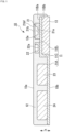
Fig. 1] Fig. 1 is a schematic sectional view illustrating one example of a configuration of a sensor device according to a first embodiment of the present invention. - [
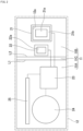
Fig. 2] Fig. 2 is a plan view of the sensor device inFig. 1 . - [
Fig. 3] Fig. 3 is a principal-part enlarged sectional view illustrating a temperature/humidity sensor of the sensor device inFig. 1 and the periphery thereof. - [
Fig. 4] Fig. 4 is a schematic sectional view illustrating one example of a configuration of a sensor device according to a second embodiment of the present invention. - [
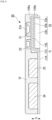
Fig. 5] Fig. 5 is a schematic sectional view illustrating one example of a configuration of a sensor device according to a third embodiment of the present invention. - Hereinafter, a sensor device as one embodiment to which the present invention is applied will be described with reference to the drawings. Each of the following embodiments is described specifically for better understanding of the gist of the invention and is not intended to limit the present invention unless otherwise specified. In addition, in the drawings used in the following description, there are cases where principal parts are illustrated in an enlarged manner for convenience of easy understanding of the features of the present invention. The dimensional ratios and the like of constituent elements are thus not necessarily the same as the actual ones.
- A sensor device in a first embodiment of the present invention will be described.
-
Fig. 1 is a schematic sectional view illustrating one example of a configuration of the sensor device according to the first embodiment of the present invention, andFig. 2 is a plan view of the sensor device inFig. 1 . - As illustrated in
Fig. 1 andFig. 2 , asensor device 10 includes aflexible substrate 11, a temperature/humidity sensor 21, anilluminance sensor 22, acontroller 23, abattery 24, anantenna 25, and anexterior body 12. - The
flexible substrate 11 in the present embodiment is a substrate (flexible substrate) having flexibility. - Such a
flexible substrate 11 having flexibility may be a substrate that is constituted by a base material in which a thin soft base film having insulation properties and a conductive metal such as copper foil are bonded together, and an electric circuit formed on the base material. For example, theflexible substrate 11 can be produced by forming wiring on a base film, such as a PET film, a PEN film, or a polyimide film, by printing of conductive ink. - The
flexible substrate 11 is bent at abent portion 11C (bent region) that is an intermediate portion in the longitudinal direction into a crank shape. In the following description, one side of theflexible substrate 11 with thebent portion 11C as a boundary is referred to as afirst region 11A, and the other side thereof is referred to as asecond region 11B. - The
flexible substrate 11 is bent at a first bending line L1 in a thickness direction t of thesensor device 10 from thefirst region 11A extending along abottom surface 10b of thesensor device 10 and is further bent at a second bending line L2 in the vicinity of the center of thesensor device 10 in the thickness direction t so as to extend parallel to asurface 10a of thesensor device 10, thereby forming thesecond region 11B. - The
first region 11A of theflexible substrate 11 constitutes a portion of thebottom surface 10b that is to be bonded to a wall surface or the like to which thesensor device 10 is attached. Thesecond region 11B of theflexible substrate 11 is disposed at a position closer than thefirst region 11A to thesurface 10a of thesensor device 10. - The
controller 23, thebattery 24, and theantenna 25 are provided at thefirst region 11A of theflexible substrate 11. Meanwhile, the temperature/humidity sensor 21 and theilluminance sensor 22 are provided at thesecond region 11B of theflexible substrate 11. - The temperature/
humidity sensor 21 detects temperature and humidity at adetection surface 21a and has a waterproof moisture-permeable material 21b that covers thedetection surface 21a. The waterproof moisture-permeable material 21b is, for example, bonded to the temperature/humidity sensor 21 via an adhesive layer and the like. In addition, the waterproof moisture-permeable material 21b is bonded directly to theexterior body 12 by insert-molding or the like or bonded thereto via an adhesive layer and the like. The waterproof moisture-permeable material 21b is a functional material that exerts waterproofness in a direction from one surface side to the other surface side and exerts permeability to water vapor. The waterproof moisture-permeable material may be in a form of fabric or may be in a form of membrane (form of film). In addition, the waterproof moisture-permeable material may be constituted by a plurality of layers. - The
illuminance sensor 22 detects the amount of light that is incident on adetection surface 22a. As the temperature/humidity sensor 21 and theilluminance sensor 22, commercially available thin sensor chips are usable as long as the sensor chips are sensors of types mountable on an IC chip. - The
controller 23 outputs (transmits) information signals of temperature, humidity, and illuminance from theantenna 25 on the basis of a temperature signal, a humidity signal, and an illuminance signal that are input from the temperature/humidity sensor 21 and theilluminance sensor 22. The information signal that is output from theantenna 25 is preferably a signal that meets the LPWA standard capable of covering a wide area with low power consumption. An example of a communication protocol is a LoRa method: Chirp Spread Spectrum modulation. - The material and the shape of the
antenna 25, and the method of manufacturing theantenna 25 are not limited as long as theantenna 25 is configured to wirelessly transmit signals that are from the temperature/humidity sensor 21 and theilluminance sensor 22 and belongs to a thin, planar, small, or micro antenna. - On the
battery 24, a solar battery is not mounted, and a primary battery is mounted as an internal power source. As the primary battery, an inexpensive primary battery distributed in the market is preferable, and a coin-type primary battery is suitably usable. On thesensor device 10, a solar battery is not mounted, and only a primary battery is mounted as an internal power source to ensure the flexibility of the entirety of thesensor device 10. Consequently, compared with a sensor device constituted by a resin case as a housing and a printed circuit board and a sensor device on which a solar battery is mounted, the costs for manufacturing thesensor device 10 can be significantly reduced. In addition, there is no problem in operation in a state without a light source, for example, during night. Thebattery 24, however, may be constituted by a secondary battery depending on the applications and the specifications thereof. - The
exterior body 12 is bonded to at least a peripheral part of theflexible substrate 11 and is formed so as to cover the temperature/humidity sensor 21, theilluminance sensor 22, thecontroller 23, thebattery 24, and theantenna 25 that are disposed at theflexible substrate 11. Theexterior body 12 is bonded to theflexible substrate 11 by, for example, insert-molding or the like. In the present embodiment, by bonding a peripheral part of theexterior body 12 to theflexible substrate 11 and aspacer member 13, the waterproofness of the inside of thesensor device 10 is ensured. - At the
exterior body 12, anopening 12a that exposes the waterproof moisture-permeable material 21b constituting the temperature/humidity sensor 21 is formed. Such anopening 12a may be, for example, an opening of a size that exposes the entire surface of the waterproof moisture-permeable material 21b or a region of the surface excluding a peripheral part. The shape of theopening 12a is not particularly limited and may be various shapes including a circular shape, a polygonal shape, and the like in plan view. - Such an
exterior body 12 is formed of a soft material having softness at least at a room temperature so as to be capable of following the deformation of theflexible substrate 11. Examples of the soft material are rubber materials, such as silicone rubber and acrylic rubber, and various types of resins, such as foamed materials of foamed urethane resin and the like, but are not particularly limited. Theexterior body 12 is preferably formed of a light-transmitting material, for example, a transparent rubber material or a transparent resin. By using such a transparent rubber material or a transparent resin in theexterior body 12, it is possible to cause light to be incident on theilluminance sensor 22 even when thedetection surface 22a of theilluminance sensor 22 is covered by theexterior body 12. - In the present embodiment, the temperature/
humidity sensor 21 is disposed such that an exposed surface 21bf of the waterproof moisture-permeable material 21b constituting the temperature/humidity sensor 21 is at a position closer than the central position in the thickness direction t of thesensor device 10 to thesurface 10a that is one surface. More specifically, the temperature/humidity sensor 21 is disposed such that the exposed surface 21bf of the waterproof moisture-permeable material 21b is at the same position as the position of thesurface 10a of thesensor device 10 or is in the vicinity of thesurface 10a. - In one example, as illustrated in the enlarged sectional view of
Fig. 3 , the temperature/humidity sensor 21 is preferably disposed at the second region 11b of theflexible substrate 11 such that a gap Δd between a surface edge portion of theopening 12a of theexterior body 12 and the exposed surface 21bf of the waterproof moisture-permeable material 21b is in a range of 5 mm or less. - As described above, the waterproof moisture-
permeable material 21b constituting the temperature/humidity sensor 21 is disposed so as to be at the same position as the position of thesurface 10a of thesensor device 10 or be in the vicinity thereof, and thesecond region 11B of theflexible substrate 11 is disposed at a position closer than thefirst region 11A to theopening 12a of theexterior body 12 in the thickness direction t. A step generated between thefirst region 11A and thesecond region 11B is compensated with thespacer member 13. Thespacer member 13 supports thesecond region 11B of theflexible substrate 11. - The
spacer member 13 is provided at a face 11Bb of thesecond region 11B opposite to a face 11Ba of thesecond region 11B facing theopening 12a of theexterior body 12. Thespacer member 13 is formed of, for example, a film or the like made of a PET resin having flexibility. In the present embodiment, thespacer member 13 has a solid structure without cavities in the inside thereof. It is thus possible to maintain the strength of thespacer member 13 to be high. - According to the
sensor device 10 in the present embodiment having the above configuration, the temperature/humidity sensor 21 having the waterproof moisture-permeable material 21b of a small size that covers thedetection surface 21a is used, and theexterior body 12 is provided with an opening that exposes the waterproof moisture-permeable material 21b. Therefore, compared with a structure in which, as with a conventional sensor device, a side surface or the like of an exterior body is provided with a large opening and in which a waterproof moisture-permeable cover is stuck to the opening from the outer side, the size of the waterproof moisture-permeable material 21b can be reduced remarkably. It is thus possible to reduce the costs relating to the expensive waterproof moisture-permeable material and possible to manufacture thesensor device 10 at low costs. - In addition, as with the present embodiment, by using the temperature/
humidity sensor 21 including the small-sized waterproof moisture-permeable material 21b, there is less likelihood of the waterproof moisture-permeable material, which is a hard material, decreasing the flexibility of thesensor device 10, compared with a configuration in which, as with the related art, an exterior body is provided with a large-sized waterproof moisture-permeable material. It is thus possible to provide thesensor device 10 having favorable flexibility over the entirety of the device. - In addition, as with the present embodiment, by bending the
flexible substrate 11 into a crank shape by thebent portion 11C, forming thesecond region 11B at a position closer than thefirst region 11A to thesurface 10a of thesensor device 10, and disposing the temperature/humidity sensor 21 at thesecond region 11B, it is possible to raise the temperature/humidity sensor 21 to a position close to thesurface 10a of thesensor device 10. It is thus possible to expose thedetection surface 21a of the temperature/humidity sensor 21 sufficiently to the outside air through the waterproof moisture-permeable material 21b, even when the size of theopening 12a formed at theexterior body 12 is reduced to expose the waterproof moisture-permeable material 21b of the temperature/humidity sensor 21, and possible to achieve both maintaining of the design by reducing the diameter of theopening 12a and precise measurement of temperature and humidity. - Further, when the temperature/
humidity sensor 21 is included together with theilluminance sensor 22, as with the present embodiment, by disposing both the temperature/humidity sensor 21 and theilluminance sensor 22 at thesecond region 11B of theflexible substrate 11, the temperature/humidity sensor 21 and theilluminance sensor 22 are disposed adjacent and close to each other. It is thus possible to improve the design by reducing the size of the opening, compared with a sensor device in the related art in which a temperature/humidity sensor and an illuminance sensor are disposed to be away from each other. - It is preferable that an adhesive layer (not illustrated) for sticking the
sensor device 10 to a structure or the like be provided on the side of thebottom surface 10b of thesensor device 10 in the present embodiment. As the adhesive layer, a commercially available industrial double-sided adhesive tape is usable. A re-peelable industrial double-sided adhesive tape is more preferably used. The surfaces of the adhesive layer on both sides may be re-peelable adhesive surfaces. It is particularly preferable to use an industrial double-sided adhesive tape of a one-side re-peelable type in which a surface on the side of thebottom surface 10b of thesensor device 10 is a general-purpose adhesive surface and in which a surface on the other side is a re-peelable adhesive surface. - As the commercially available industrial double-sided adhesive tape, for example, a DAITAC (registered trademark) industrial double-sided adhesive tape, manufactured by DIC Corporation, is usable. Examples of the industrial double-sided adhesive tape of the one-side re-peelable type are DAITAC (registered trademark) industrial double-sided adhesive tapes, manufactured by DIC Corporation, having the product numbers of "#8800DR", "#8612DFT", "#8616DJ-50", "#8616DJ black(N)", and the like.
- On the side of the
surface 10a of thesensor device 10, a decoration layer formed of a light-shielding rubber sheet or the like may be further formed to improve the design. In this case, openings may be provided at parts that overlap the temperature/humidity sensor 21 and theilluminance sensor 22. - A sensor device in a second embodiment of the present invention will be described.
-
Fig. 4 is a schematic sectional view illustrating one example of a configuration of the sensor device according to the second embodiment of the present invention. In the following description, the same configurations as those in the above-described first embodiment are given identical numerals, and duplicate description thereof is omitted. - As illustrated in
Fig. 4 , in asensor device 30, aspacer member 33 that compensates a step between thesecond region 11B and thefirst region 11A of theflexible substrate 11 has a box structure constituted by aperipheral part 33a and anupper surface part 33b. In other words, thespacer member 33 has aspace portion 33c that is defined by theperipheral part 33a and theupper surface part 33b. Thespacer member 33 may have a hollow structure having a space portion in the inside thereof. - By providing the
spacer member 33 with thespace portion 33c, theupper surface part 33b can be thermally insulated in the thickness direction t. In addition, the weight of thespacer member 33 can be reduced. It is thus possible to improve the measurement accuracy, reduce the weight, and further improve the flexibility in thesensor device 30. - A sensor device in a third embodiment of the present invention will be described.
-
Fig. 5 is a schematic sectional view illustrating one example of a configuration of the sensor device according to the third embodiment of the present invention. In the following description, the same configurations as those in the above-described first embodiment are given identical numerals, and duplicate description thereof is omitted. - As illustrated in
Fig. 5 , in asensor device 40, a flexible substrate 41 is constituted by the two substrates of afirst substrate 41A and asecond substrate 41B. - The
first substrate 41A constituting the flexible substrate 41 is formed along abottom surface 40b of thesensor device 40. Thesecond substrate 41B constituting the flexible substrate 41 is formed so as to overlap a portion of thefirst substrate 41A in the thickness direction t, to be spaced from thefirst substrate 41A in the thickness direction t, and to be closer than thefirst substrate 41A to asurface 40a of thesensor device 40. - In addition, a connection portion 41C that electrically connects the
first substrate 41A and thesecond substrate 41B to each other is formed between a portion in the vicinity of the center of thefirst substrate 41A and an end portion of thesecond substrate 41B. Aspacer member 43 is formed between thefirst substrate 41A and thesecond substrate 41B that are spaced from each other in the thickness direction t. - The
spacer member 43 is provided at a face 41Bb of thesecond substrate 41B opposite to a face 41Ba of thesecond substrate 41B facing anopening 42a of anexterior body 42. Such aspacer member 43 supports thesecond substrate 41B such that thesecond substrate 41B is closer than thefirst substrate 41A to thesurface 40a of thesensor device 40. - In the present embodiment, a
controller 53, abattery 54, and an antenna (not illustrated) are disposed at thefirst substrate 41A. In addition, a temperature/humidity sensor 51 and anilluminance sensor 52 are disposed adjacent to each other at thesecond substrate 41B. - By thus disposing the temperature/
humidity sensor 51 and theilluminance sensor 52 at thesecond substrate 41B that is provided closer than thefirst substrate 41A to thesurface 40a of thesensor device 40, it is possible to dispose the temperature/humidity sensor 51 and theilluminance sensor 52 on the side of thesurface 40a of thesensor device 40. - The
exterior body 42 is bonded to a peripheral part of the flexible substrate 41 and an end portion of thespacer member 43 and is formed so as to cover the temperature/humidity sensor 51, theilluminance sensor 52, thecontroller 53, thebattery 54, and the antenna (not illustrated) that are disposed at the flexible substrate 41. Also in the present embodiment, by bonding a peripheral part of theexterior body 42 to the peripheral part of the flexible substrate 41 and to the end portion of thespacer member 43, the waterproofness in the inside of thesensor device 40 is ensured. - The
opening 42a that exposes a waterproof moisture-permeable material 51b constituting the temperature/humidity sensor 51 is formed at theexterior body 42. Such anopening 42a may be, for example, an opening of a size that exposes the entire surface of the waterproof moisture-permeable material 51b or a region of the surface excluding a peripheral part. The shape of theopening 42a is not particularly limited and may be various shapes including a circular shape, a polygonal shape, and the like in plan view. - Such an
exterior body 42 is formed of a soft material having softness at least at a room temperature so as to be capable of following the deformation of the flexible substrate 41. Examples of the soft material are rubber materials, such as silicone rubber, and various types of resins, such as an epoxy resin, but are not particularly limited. Theexterior body 42 is preferably formed of a light-transmitting material, for example, a transparent rubber material or a transparent resin. - In such a sensor device in the third embodiment, the flexible substrate 41 is not provided with a bent portion and is constituted by the two substrates of the
first substrate 41A and thesecond substrate 41B, and thesecond substrate 41B is disposed to be spaced from thefirst substrate 41A and to be closer than thefirst substrate 41A to thesurface 40a of thesensor device 40. Consequently, processing of bending the flexible substrate 41 is not necessary in the manufacture of thesensor device 40. It is thus possible to manufacture thesensor device 40 at lower costs. - While some embodiments of the present invention have been described above, these embodiments are presented as examples and are not intended to limit the scope of the invention. These embodiments can be implemented in the other various forms, and various omissions, replacements, and changes can be performed in these embodiments within a range that does not depart from the spirit of the invention. The embodiments and modifications thereof are included in the scope and the gist of the invention and also included in the invention disclosed in the claims and the scope equivalent thereto.
- For example, in each of the embodiments described above, a configuration in which the temperature/humidity sensor and the illuminance sensor are included as sensors is presented as an example. The present invention, however, may have a configuration without the illuminance sensor as long as the present invention includes at least the temperature/humidity sensor. In this case, it is not necessary to use a light-transmitting (transparent) material in the exterior body. For example, a flexible and light-transmitting material such as black rubber is also usable as the exterior body. In addition, any functional sensors other than the illuminance sensor may be included.
- Further, for example, in each of the embodiments described above, a configuration in which the temperature/humidity sensor and the illuminance sensor are provided at the second region or the second substrate that constitutes the flexible substrate and in which the battery, the controller, and the antenna are provided at the first region or the first substrate that constitutes the flexible substrate is presented as an example. However, it is sufficient that at least the temperature/humidity sensor be disposed at the second region or the second substrate of the flexible substrate that is present at a position closer to the surface of the sensor device. One or a plurality of any other members (the controller, the battery, the antenna, and the like) may be provided at the second region or the second substrate that constitutes the flexible substrate. The arrangement layout of these members are not limited.
- In each of the embodiment described above, the
flexible substrate 11 is bent in a crank shape in a sectional view (for example,Fig. 1 ). Theflexible substrate 11 is, however, not limited thereto and may be bent in a U-shape in a sectional view. In this case, the temperature/humidity sensor and the illuminance sensor (or at least the temperature/humidity sensor) may be provided on one main surface side of theflexible substrate 11 and may be electrically connected via a conductive portion such as a through hole to any other member such as a battery or the like formed on the other main surface side. - In addition, in the
flexible substrate 11, thefirst region 11A and thesecond region 11B are provided at different heights (levels) in the thickness direction t (for example,Fig. 1 ). Thefirst region 11A and thesecond region 11B are, however, not limited thereto and may be provided at the same height in the thickness direction. In other words, theflexible substrate 11 may not have the bent portion, and thefirst region 11A and thesecond region 11B may constitute an identical plane or a substantially identical plane. In this case, to suppress heat transmission from an attached surface to which thesensor device 10 is attached, a heat insulating layer constituted by a heat insulating sheet or the like may be provided at a surface of theflexible substrate 11 opposite to a surface thereof at which the temperature/humidity sensor 21 is provided. By thus simply configuring theflexible substrate 11, it is possible to manufacture thesensor device 10 at low costs. - The sensor device in the present invention has favorable flexibility and can achieve a low-cost sensor device by reducing costs relating to an expensive waterproof moisture-permeable material. Therefore, for example, an operator at a work site can easily attach and detach the sensor device having flexibility to and from a plurality of portions of a column and the like under construction. Consequently, it is possible to accurately grasp the work environment of the site and possible to manage the health state of the operator by measuring, at an appropriate position near the operator, the temperature and the humidity at the site. Accordingly, it is possible to suitably use the sensor device of the present invention at various work sites of construction, building, and the like.
-
- 10
- sensor device
- 11
- flexible substrate
- 11A
- first region
- 11B
- second region
- 11C
- bent portion
- 12
- exterior body
- 13
- spacer member
- 21
- temperature/humidity sensor
- 21b
- waterproof moisture-permeable material
- 22
- illuminance sensor
- 23
- controller
- 24
- battery
- 25
- antenna
Claims (9)
- A sensor device having flexibility and comprising a flexible substrate, a temperature/humidity sensor that is connected to the flexible substrate, and an exterior body that is formed of a soft material,wherein the temperature/humidity sensor has a waterproof moisture-permeable material that covers a detection surface,wherein the exterior body has an opening that exposes the waterproof moisture-permeable material, andwherein the flexible substrate is bonded at at least a peripheral part of the flexible substrate to the exterior body.
- The sensor device according to claim 1, wherein the temperature/humidity sensor is disposed such that an exposed surface of the waterproof moisture-permeable material is at a position closer than a central position in a thickness direction of the sensor device to one surface.
- The sensor device according to claim 2, wherein a gap between a surface edge portion of the opening of the exterior body and the exposed surface of the waterproof moisture-permeable material is in a range of 5 mm or less.
- The sensor device according to any one of claims 1 to 3,wherein the flexible substrate has a bent region, a first region that is provided at one side with the bent region as a boundary, and a second region that is provided at another side,wherein the second region is disposed at a position closer than the first region to the opening of the exterior body, andwherein the temperature/humidity sensor is disposed at the second region of the flexible substrate.
- The sensor device according to claim 4, further comprising an illuminance sensor that is provided at the second region.
- The sensor device according to claim 4, wherein a battery that supplies electric power to the temperature/humidity sensor is provided at the first region.
- The sensor device according to any one of claims 1 to 3 wherein the flexible substrate is constituted by a first substrate and a second substrate that are electrically connected to each other,wherein the second substrate is disposed at a position closer than the first substrate to the opening of the exterior body,wherein the temperature/humidity sensor is disposed at the second substrate, andwherein a spacer member is provided at a surface of the second substrate opposite to a surface of the second substrate facing the opening of the exterior body.
- The sensor device according to claim 7, further comprising an illuminance sensor that is provided at the second substrate.
- The sensor device according to claim 7, wherein a battery that supplies electric power to the temperature/humidity sensor is provided at the first substrate.
Applications Claiming Priority (2)
| Application Number | Priority Date | Filing Date | Title |
|---|---|---|---|
| JP2020110084 | 2020-06-26 | ||
| PCT/JP2021/022017 WO2021261257A1 (en) | 2020-06-26 | 2021-06-10 | Sensor device |
Publications (2)
| Publication Number | Publication Date |
|---|---|
| EP4174449A1 true EP4174449A1 (en) | 2023-05-03 |
| EP4174449A4 EP4174449A4 (en) | 2024-06-19 |
Family
ID=79281114
Family Applications (1)
| Application Number | Title | Priority Date | Filing Date |
|---|---|---|---|
| EP21829903.0A Withdrawn EP4174449A4 (en) | 2020-06-26 | 2021-06-10 | SENSOR DEVICE |
Country Status (4)
| Country | Link |
|---|---|
| US (1) | US12150246B2 (en) |
| EP (1) | EP4174449A4 (en) |
| JP (1) | JP7173412B2 (en) |
| WO (1) | WO2021261257A1 (en) |
Families Citing this family (3)
| Publication number | Priority date | Publication date | Assignee | Title |
|---|---|---|---|---|
| JP6722737B2 (en) * | 2018-09-28 | 2020-07-15 | 富士通株式会社 | Sensor device |
| CN114755263B (en) * | 2022-06-16 | 2022-09-27 | 苏州大学 | Auxiliary device for detecting moisture and heat performance of fabric |
| US11821759B1 (en) | 2022-09-20 | 2023-11-21 | Soochow University | Auxiliary device for detecting damp-hot performance of fabric |
Family Cites Families (7)
| Publication number | Priority date | Publication date | Assignee | Title |
|---|---|---|---|---|
| US20140076026A1 (en) | 2012-09-20 | 2014-03-20 | Therm-O-Disc, Incorporated | Relative humidity sensor |
| JP6533380B2 (en) * | 2013-11-11 | 2019-06-19 | 日本特殊陶業株式会社 | Sensor |
| JP6641701B2 (en) * | 2014-03-14 | 2020-02-05 | 株式会社リコー | Atmosphere sensor, method for manufacturing the same, and method for manufacturing printed matter |
| KR102288437B1 (en) * | 2014-11-21 | 2021-08-10 | 삼성전자주식회사 | A foldable electronic device |
| US10338132B2 (en) * | 2016-04-19 | 2019-07-02 | Analog Devices Global | Wear-out monitor device |
| EP3751236B1 (en) | 2018-02-06 | 2023-10-18 | DIC Corporation | Wireless sensor device and wireless sensor device kit |
| JP6722737B2 (en) * | 2018-09-28 | 2020-07-15 | 富士通株式会社 | Sensor device |
-
2021
- 2021-06-10 WO PCT/JP2021/022017 patent/WO2021261257A1/en not_active Ceased
- 2021-06-10 US US18/009,186 patent/US12150246B2/en active Active
- 2021-06-10 JP JP2022531728A patent/JP7173412B2/en active Active
- 2021-06-10 EP EP21829903.0A patent/EP4174449A4/en not_active Withdrawn
Also Published As
| Publication number | Publication date |
|---|---|
| US12150246B2 (en) | 2024-11-19 |
| JPWO2021261257A1 (en) | 2021-12-30 |
| JP7173412B2 (en) | 2022-11-16 |
| US20230262884A1 (en) | 2023-08-17 |
| WO2021261257A1 (en) | 2021-12-30 |
| EP4174449A4 (en) | 2024-06-19 |
Similar Documents
| Publication | Publication Date | Title |
|---|---|---|
| US12150246B2 (en) | Sensor device | |
| EP3741099B1 (en) | Electronic device conduit structure and electronic device including same | |
| EP2633232B1 (en) | Lighting assembly | |
| EP4271153A1 (en) | Electronic device comprising heat dissipation structure | |
| JP6403929B1 (en) | Operation equipment | |
| US12232267B2 (en) | Electronics assembly | |
| EP3364664B1 (en) | Microphone unit | |
| EP3751236B1 (en) | Wireless sensor device and wireless sensor device kit | |
| CN102401252A (en) | LED module, LED light bar and manufacturing method of LED module | |
| JP4315986B2 (en) | Electronic device with light emitting diode | |
| JP7158528B2 (en) | Network communication device with electrostatic protection function | |
| US20210262863A1 (en) | Sensor device | |
| JP2017058279A (en) | Sensor module and sensor device including the same | |
| US11229122B2 (en) | Increasing exposure of integrated circuit components | |
| CN212933536U (en) | Fingerprint module and photosensitive module combined structure and electronic device | |
| JP2020014172A (en) | Beacon device with waterproof structure | |
| JP4138762B2 (en) | Heat sensor | |
| EP4010208B1 (en) | Tire electronics assembly | |
| CN119811213B (en) | A display module with an isolated beacon structure | |
| CN108489556B (en) | Combined heart rate module | |
| JP2020194849A (en) | Electronic apparatus | |
| CN112822315A (en) | Mobile terminal | |
| US20110290990A1 (en) | construction unit, comprising a light detector, and a process to assemble such construction unit to a carrier, such as printed circuit card | |
| JPWO2017126456A1 (en) | Communication device |
Legal Events
| Date | Code | Title | Description |
|---|---|---|---|
| STAA | Information on the status of an ep patent application or granted ep patent |
Free format text: STATUS: THE INTERNATIONAL PUBLICATION HAS BEEN MADE |
|
| PUAI | Public reference made under article 153(3) epc to a published international application that has entered the european phase |
Free format text: ORIGINAL CODE: 0009012 |
|
| STAA | Information on the status of an ep patent application or granted ep patent |
Free format text: STATUS: REQUEST FOR EXAMINATION WAS MADE |
|
| 17P | Request for examination filed |
Effective date: 20221228 |
|
| AK | Designated contracting states |
Kind code of ref document: A1 Designated state(s): AL AT BE BG CH CY CZ DE DK EE ES FI FR GB GR HR HU IE IS IT LI LT LU LV MC MK MT NL NO PL PT RO RS SE SI SK SM TR |
|
| DAV | Request for validation of the european patent (deleted) | ||
| DAX | Request for extension of the european patent (deleted) | ||
| A4 | Supplementary search report drawn up and despatched |
Effective date: 20240521 |
|
| RIC1 | Information provided on ipc code assigned before grant |
Ipc: G01D 11/30 20060101ALI20240515BHEP Ipc: G01D 11/24 20060101AFI20240515BHEP |
|
| STAA | Information on the status of an ep patent application or granted ep patent |
Free format text: STATUS: EXAMINATION IS IN PROGRESS |
|
| STAA | Information on the status of an ep patent application or granted ep patent |
Free format text: STATUS: THE APPLICATION HAS BEEN WITHDRAWN |
|
| 17Q | First examination report despatched |
Effective date: 20250925 |
|
| 18W | Application withdrawn |
Effective date: 20251001 |