EP4174433A1 - Heat exchanger for power electronics - Google Patents
Heat exchanger for power electronics Download PDFInfo
- Publication number
- EP4174433A1 EP4174433A1 EP22204246.7A EP22204246A EP4174433A1 EP 4174433 A1 EP4174433 A1 EP 4174433A1 EP 22204246 A EP22204246 A EP 22204246A EP 4174433 A1 EP4174433 A1 EP 4174433A1
- Authority
- EP
- European Patent Office
- Prior art keywords
- heat exchanger
- power electronics
- fluid
- flow
- fluid pathways
- Prior art date
- Legal status (The legal status is an assumption and is not a legal conclusion. Google has not performed a legal analysis and makes no representation as to the accuracy of the status listed.)
- Granted
Links
Images




Classifications
-
- F—MECHANICAL ENGINEERING; LIGHTING; HEATING; WEAPONS; BLASTING
- F24—HEATING; RANGES; VENTILATING
- F24F—AIR-CONDITIONING; AIR-HUMIDIFICATION; VENTILATION; USE OF AIR CURRENTS FOR SCREENING
- F24F1/00—Room units for air-conditioning, e.g. separate or self-contained units or units receiving primary air from a central station
- F24F1/06—Separate outdoor units, e.g. outdoor unit to be linked to a separate room comprising a compressor and a heat exchanger
- F24F1/20—Electric components for separate outdoor units
- F24F1/24—Cooling of electric components
-
- F—MECHANICAL ENGINEERING; LIGHTING; HEATING; WEAPONS; BLASTING
- F28—HEAT EXCHANGE IN GENERAL
- F28F—DETAILS OF HEAT-EXCHANGE AND HEAT-TRANSFER APPARATUS, OF GENERAL APPLICATION
- F28F3/00—Plate-like or laminated elements; Assemblies of plate-like or laminated elements
- F28F3/12—Elements constructed in the shape of a hollow panel, e.g. with channels
-
- F—MECHANICAL ENGINEERING; LIGHTING; HEATING; WEAPONS; BLASTING
- F24—HEATING; RANGES; VENTILATING
- F24F—AIR-CONDITIONING; AIR-HUMIDIFICATION; VENTILATION; USE OF AIR CURRENTS FOR SCREENING
- F24F13/00—Details common to, or for air-conditioning, air-humidification, ventilation or use of air currents for screening
- F24F13/22—Means for preventing condensation or evacuating condensate
- F24F13/222—Means for preventing condensation or evacuating condensate for evacuating condensate
-
- F—MECHANICAL ENGINEERING; LIGHTING; HEATING; WEAPONS; BLASTING
- F24—HEATING; RANGES; VENTILATING
- F24F—AIR-CONDITIONING; AIR-HUMIDIFICATION; VENTILATION; USE OF AIR CURRENTS FOR SCREENING
- F24F13/00—Details common to, or for air-conditioning, air-humidification, ventilation or use of air currents for screening
- F24F13/30—Arrangement or mounting of heat-exchangers
-
- H—ELECTRICITY
- H05—ELECTRIC TECHNIQUES NOT OTHERWISE PROVIDED FOR
- H05K—PRINTED CIRCUITS; CASINGS OR CONSTRUCTIONAL DETAILS OF ELECTRIC APPARATUS; MANUFACTURE OF ASSEMBLAGES OF ELECTRICAL COMPONENTS
- H05K7/00—Constructional details common to different types of electric apparatus
- H05K7/20—Modifications to facilitate cooling, ventilating, or heating
- H05K7/2089—Modifications to facilitate cooling, ventilating, or heating for power electronics, e.g. for inverters for controlling motor
- H05K7/20936—Liquid coolant with phase change
-
- F—MECHANICAL ENGINEERING; LIGHTING; HEATING; WEAPONS; BLASTING
- F28—HEAT EXCHANGE IN GENERAL
- F28D—HEAT-EXCHANGE APPARATUS, NOT PROVIDED FOR IN ANOTHER SUBCLASS, IN WHICH THE HEAT-EXCHANGE MEDIA DO NOT COME INTO DIRECT CONTACT
- F28D21/00—Heat-exchange apparatus not covered by any of the groups F28D1/00 - F28D20/00
- F28D2021/0019—Other heat exchangers for particular applications; Heat exchange systems not otherwise provided for
- F28D2021/0068—Other heat exchangers for particular applications; Heat exchange systems not otherwise provided for for refrigerant cycles
- F28D2021/0071—Evaporators
Definitions
- the mating surfaces of the plates 32, 34 can include precision surfaces formed from a process having highly accurate and precise dimensional control, such as through computer numerical control (CNC) machining process and/or net shape, or near net shape manufacturing process.
- CNC computer numerical control
- a sealing material can be disposed between the plates 32, 34 to aide in preventing leakage from the fluid circuit.
- the flow of fluid 22 enters the heat exchanger 14 at the heat exchanger inlet 26 and is distributed to the fluid pathways 20 via the inlet manifold 30.
- the heat exchanger 14 conducts thermal energy from the power electronics devices 12 and thermal energy is exchanged with the flow of fluid 22 flowing through the fluid pathways 20, resulting in cooling of the power electronics devices 12.
- the vapor flow of fluid 22 is then collected at the outlet manifold 28 and exits the heat exchanger 14 at the heat exchanger outlet 24.
- the flow of fluid 22 provided to the heat exchanger 14 is diverted from the condenser 72 and in some embodiments enters the heat exchanger 14 in a liquid phase with 0% vapor quality or up to 20% vapor quality.
Landscapes
- Engineering & Computer Science (AREA)
- Mechanical Engineering (AREA)
- General Engineering & Computer Science (AREA)
- Chemical & Material Sciences (AREA)
- Combustion & Propulsion (AREA)
- Microelectronics & Electronic Packaging (AREA)
- Physics & Mathematics (AREA)
- Thermal Sciences (AREA)
- Cooling Or The Like Of Electrical Apparatus (AREA)
- Heat-Exchange Devices With Radiators And Conduit Assemblies (AREA)
- Air-Conditioning For Vehicles (AREA)
Abstract
Description
- The present invention pertains to the art of heat exchangers, and more particularly to heat exchangers for cooling power electronics.
- Power electronics devices such as motor drives generate waste heat during operation of the device. Additionally, when the power electronics devices heat up the operational efficiency of the devices can degrade adding to the amount of heat generated. When utilized in a refrigeration system to drive, for example, a compressor of the refrigeration system, effective thermal integration of these devices can be important aspect to the system's overall efficiency and reliability. Consequently, a goal of the system integrator is to maintain these components within a range of operating temperatures which will maximize the system efficiency. Accordingly, there remains a need in the art for heat exchangers configured to closely integrate with power electronic devices which can maintain optimal temperatures for these components under a variety of load conditions.
- According to a first aspect of the invention, a power electronics assembly is provided. The power electronics assembly includes one or more power electronics devices, and a heat exchanger to which the one or more power electronics devices are mounted. The heat exchanger includes one or more fluid pathways extending through the heat exchanger to transfer thermal energy from the one or more power electronics devices into a flow of fluid passing through the one or more fluid pathways. The flow of fluid is a flow of liquid refrigerant diverted from a condenser of a heating, ventilation, and air conditioning (HVAC) system. The one or more power electronics devices includes at least one power electronics device located on each opposing lateral side of the heat exchanger.
- The heat exchanger may include multiple columns of the fluid pathways arranged between the opposing lateral sides of the heat exchanger.
- Each column of the multiple columns of fluid pathways may define an independent fluid circuit.
- Each column of fluid pathways may be configured to cool the at least one power electronics device at the lateral side of the heat exchanger nearest each column.
- The one or more fluid pathways may include one or more fins extending inwardly from a pathway inner wall.
- Each fin of the one or more fins may have a fin height in the range of 0.2 millimeters to 0.5 millimeters.
- One or more condensate drainage passages may be formed in an exterior surface of the heat exchanger configured to drain condensate formed on one or more of the one or more power electronics devices or on the heat exchanger.
- The one or more condensate drainage passages may have a T-shaped cross-section.
- The one or more fluid pathways may extend off of horizontal along a fluid pathway length.
- According to a second aspect of the invention, a method of cooling one or more power electronics devices is provided. The method includes securing the one or more power electronics devices to a heat exchanger. The heat exchanger includes one or more fluid pathways. A flow of fluid is circulated through one or more fluid pathways to transfer thermal energy from the one or more power electronics devices to the flow of fluid passing through the one or more fluid pathways. The flow of fluid is a flow of liquid refrigerant diverted from a condenser of a heating, ventilation, and air conditioning (HVAC) system. At least one power electronics device is located on each opposing lateral side of the heat exchanger.
- The heat exchanger may include multiple columns of the fluid pathways arranged between the opposing lateral sides of the heat exchanger.
- A first flow of fluid may be circulated through a first column of fluid pathways, and a second flow of fluid may be circulated through a second column of fluid pathways.
- A first power electronics device located at a first lateral side of the heat exchanger may be cooled via the first flow of fluid and a second power electronics device located at a second lateral side of the heat exchanger may be cooled via the second flow of fluid.
- The one or more fluid pathways may include one or more fins extending inwardly from a pathway inner wall.
- Each fin of the one or more fins may have a fin height in the range of 0.2 millimeters to 0.5 millimeters.
- Condensate formed on one or more of the one or more power electronics devices or on the heat exchanger may be drained via one or more condensate drainage passages formed in an exterior surface of the heat exchanger.
- The one or more condensate drainage passages may have a T-shaped cross-section.
- The one or more fluid pathways may extend off or horizontal along a fluid pathway length.
- The following descriptions should not be considered limiting. Certain exemplary embodiments of the invention, will now be described, with reference to the accompanying drawings, in which like elements are numbered alike.
-
FIG. 1 shows an exemplary power electronics assembly; -
FIG. 2 shows an exemplary heating, ventilation, and air conditioning (HVAC) system; -
FIG. 3 shows a heat exchanger of an exemplary power electronics assembly; -
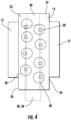
FIG. 4 shows an exemplary heat exchanger having multiple fluid pathway columns; -
FIG. 5 shows an exemplary heat exchanger having multiple fluid pathway columns; -
FIG. 6 shows a cross-sectional view of an exemplary fluid pathway having internal fins; -
FIG. 7 shows a perspective view of an exemplary fin structure; -
FIG. 8 shows an exemplary helix angle of a fin of a fluid pathway; -
FIG. 9 shows a cross-sectional view of an exemplary heat exchanger having condensate drainage passages; and -
FIG. 10 shows a view of an exemplary heat exchanger showing an orientation of fluid pathways. - A detailed description of one or more embodiments of the disclosed apparatus and method are presented herein by way of exemplification and not limitation with reference to the Figures.
- Illustrated in
FIG. 1 is an embodiment of apower electronics assembly 10. Thepower electronics assembly 10 includes one or morepower electronics devices 12 mounted to aheat exchanger 14 utilized to reject and dissipate thermal energy generated by thepower electronics devices 12 during operation. In some embodiments, thepower electronics devices 12 include a variable frequency drive (VFD) operably connected to acompressor 16 of a heating, ventilation, and air conditioning (HVAC)system 18. - Referring to
FIG. 2 , theHVAC system 18 includes, for example, avapor compression circuit 70 including thecompressor 16, acondenser 72, anexpansion device 74 and anevaporator 76 arranged in series and having a volume of refrigerant flowing therethrough. Thepower electronics assembly 10 is connected to thevapor compression circuit 70 such that a portion of the flow of liquid refrigerant exiting thecondenser 72 is diverted through theheat exchanger 14, bypassing theexpansion device 74 and is directed from theheat exchanger 14 to theevaporator 76. The liquid refrigerant from thecondenser 72 absorbs thermal energy generated by thepower electronics devices 12. This thermal energy generated by thepower electronics devices 12 may cause the refrigerant passing through theheat exchanger 14 to boil, changing phase of the refrigerant from liquid to vapor inside theheat exchanger 14. - Referring now to
FIG. 3 , theexemplary heat exchanger 14 is illustrated in more detail. As shown, theheat exchanger 14 includes a plurality of enclosedfluid pathways 20 enabling a flow offluid 22 such as, for example, refrigerant, glycol, or water to flow therein. Thefluid pathways 20 extend between a heat exchanger inlet 26 through which the flow offluid 22 enters theheat exchanger 14, and aheat exchanger outlet 24 through which the flow offluid 22 exits theheat exchanger 14. Theheat exchanger inlet 26 is connected to thefluid pathways 20 via aninlet manifold 30 to distribute the flow offluid 22 to thefluid pathways 20, and similarly theheat exchanger outlet 24 is connected to thefluid pathways 20 via anoutlet manifold 28. Immediately downstream of theinlet manifold 30,orifices 80 of different diameters, increasing with increasing distance from theheat exchanger inlet 26 are provided to distribute the flow offluid 22 from theinlet manifold 30 equally among all of thefluid pathways 20. The enhancement features described in the following text will be in thefluid pathways 20 downstream of therespective orifices 80. - In some embodiments, the
heat exchanger 14 is formed from a metal material, such as aluminum, aluminum alloy, steel, steel alloy, copper, copper alloy, or the like, and referring again toFIG. 1 , may be formed from two ormore plates plates fluid pathways 20, theinlet manifold 30, theoutlet manifold 28, the heat exchanger inlet 26 and/or theheat exchanger outlet 24 formed therein. The mating surfaces of theplates plates plates - In operation, the flow of
fluid 22, liquid refrigerant from thecondenser 72, enters theheat exchanger 14 at theheat exchanger inlet 26 and is distributed to thefluid pathways 20 via theinlet manifold 30. Theheat exchanger 14 conducts thermal energy from thepower electronics devices 12 and thermal energy is exchanged with the flow offluid 22 flowing through thefluid pathways 20, resulting in cooling of thepower electronics devices 12. The vapor flow offluid 22 is then collected at theoutlet manifold 28 and exits theheat exchanger 14 at theheat exchanger outlet 24. The flow offluid 22 provided to theheat exchanger 14 is diverted from thecondenser 72 and in some embodiments enters theheat exchanger 14 in a liquid phase with 0% vapor quality or up to 20% vapor quality. The presently disclosedheat exchanger 14 may be operated to ensure the vapor quality of the flow offluid 22 exiting theheat exchanger 14 has a vapor quality of from about 25% to about 80%, or in another embodiment from about 40% to about 60%, or in yet another embodiment from about 45% to about 55%, or about 50%. The vapor quality change happens as the heat frompower electronics devices 12 is absorbed by the flow and used for phase change of the liquid refrigerant to vapor while travelling from theheat exchanger inlet 26 to theheat exchanger outlet 24. In the present disclosure, features of theheat exchanger 14 are disclosed which improve performance of theheat exchanger 14, many of which are features to improve boiling performance of the flow offluid 22, the refrigerant from thecondenser 72. - Referring now to
FIG. 4 , in some embodiments,power electronics devices 12 are installed to bothlateral sides 36 of theheat exchanger 14. To accomplish cooling of thepower electronics devices 12 in such configurations, theheat exchanger 14 may have one, or two ormore pathway columns 38 offluid pathways 20 arranged between the lateral sides 36. This may increase the flow offluid 22 through theheat exchanger 14, and enable the fluid 22 to be in closer proximity to the respective power electronics devices 12 (as compared to a single column positioned in the center of the lateral sides 36). In such configurations, theheat exchanger 14 may have an additionalmiddle plate 40 between theplates pathway column 38 is formed. The columns can be adjacent to each other to increase thermal mass of theheat exchanger 14 or in a staggered arrangement to reduce the thermal mass hence weight of theheat exchanger 14. - In some embodiments, such as shown in
FIG. 4 , the twopathway columns 38 share acommon inlet manifold 30 and acommon outlet manifold 28. In other embodiments, such as illustrated inFIG. 5 , afirst pathway column 38a utilizes afirst inlet manifold 30a and afirst outlet manifold 28a having a first flow of fluid 22a defining a first circuit. Similarly, asecond pathway column 38b utilizes asecond inlet manifold 30b and asecond outlet manifold 28b having a second flow of fluid 22b defining a second circuit. Having separate first and second circuits in theheat exchanger 14 allows for the flow of each fluid 22a, 22b to be tuned separately to meet the cooling requirements for the power electronics devices at eachlateral side 36 of theheat exchanger 14. For example, in some embodiments, the fluid pathways 20a of thefirst pathway column 38a may be the same configuration as the fluid pathways 20b of thesecond pathway column 38b, or the configurations may be different having, for example, different pathway sizes, internal or external features, different materials, or the like. Further, a number of pathways in each of thepathway columns pathway column - Referring now to
FIG. 6 and 7 , in some embodiments, thefluid pathways 20 include a plurality offins 42 extending radially inwardly from a pathwayinner wall 44 to afin tip 46. Eachfin 42 has acircumferential base width 48 and acircumferential tip width 50, as well as a circumferential fin spacing 52 betweenadjacent fins 42, defined at the pathwayinner wall 44. In some embodiments, thetip width 50 is in the range of 0.01 millimeters to 0.1 millimeters. Additionally, thefin spacing 52 may be in the range of 0.05 millimeters and 0.5 millimeters. Thefins 42 further each have afin height 54 from the pathwayinner wall 44 to thefin tip 46. Thefin height 54 may be in a range of, for example, 0.2 millimeters to 0.5 millimeters, depending on a pathway hydraulic diameter, which in some embodiments is in the range of 5 millimeters to 20 millimeters. In some embodiments, a number offins 42 in afluid pathway 20 is in the range of 30-80fins 42. The plurality offins 42 may extend substantially linearly parallel to a pathwaycentral axis 56 or alternatively may extend helically about the pathwaycentral axis 56 along a length of thepathway 20, at ahelix angle 82 in the range of 10 degrees to 30 degrees, such as shown inFIG. 8 . Additionally, referring again toFIG. 7 , thefins 42 have anapex angle 84 between adjacent sidewalls of thefins 42, which may be in the range of 20 degrees to 60 degrees. - Referring now to
FIG. 9 , a heat exchangerouter wall 58 may includecondensate drainage passages 60 located between adjacentpower electronics devices 12. During operation, condensate may form on the cooler walls of the heat exchangerouter wall 58. Thecondensate drainage passages 60, when present, collect the condensate and drain the condensate away from thepower electronics devices 12. In some embodiments, thecondensate drainage passages 60 have a T-shaped cross-section to contain the condensate and drain the condensate away from the power electronics devices. Referring now toFIG. 10 , thefluid pathways 20 may extend in a direction off of horizontal along the fluid pathway length. This promotes drainage of the flow offluid 22 from theheat exchanger 14 via gravity when theHVAC system 18 is deactivated. In some embodiments, such as shown, thefluid pathways 20 are chevron-shaped along the fluid pathway length, while in other embodiments thefluid pathways 20 are simply inclined in one direction relative to horizontal. Other configurations offluid pathways 20 are contemplated within the scope of the present disclosure. - The configurations of
heat exchangers 14 andpower electronics assemblies 10 disclosed herein increase heat transfer area in thefluid pathways 20 and promote convective evaporation and boiling of the flow offluid 22 in theheat exchanger 14 to improve heat transfer rate of theheat exchanger 14. Further, the configurations reduce a volume ofheat exchanger 14 for cooling thepower electronics devices 12. - The term "about" is intended to include the degree of error associated with measurement of the particular quantity based upon the equipment available at the time of filing the application.
- The terminology used herein is for the purpose of describing particular embodiments only and is not intended to be limiting of the present invention. As used herein, the singular forms "a", "an" and "the" are intended to include the plural forms as well, unless the context clearly indicates otherwise. It will be further understood that the terms "comprises" and/or "comprising," when used in this specification, specify the presence of stated features, integers, steps, operations, elements, and/or components, but do not preclude the presence or addition of one or more other features, integers, steps, operations, element components, and/or groups thereof.
- While the present invention has been described with reference to an exemplary embodiment or embodiments, it will be understood by those skilled in the art that various changes may be made and equivalents may be substituted for elements thereof without departing from the scope of the present invention. In addition, many modifications may be made to adapt a particular situation or material to the teachings of the present disclosure without departing from the essential scope thereof. Therefore, it is intended that the present invention not be limited to the particular embodiment disclosed as the best mode contemplated for carrying out this present invention, but that the present invention will include all embodiments falling within the scope of the claims.
Claims (15)
- A power electronics assembly (10), comprising:one or more power electronics devices (12); anda heat exchanger (14) to which the one or more power electronics devices (12) are mounted, the heat exchanger (14) comprising:
one or more fluid pathways (20, 20a, 20b) extending through the heat exchanger (14) to transfer thermal energy from the one or more power electronics devices (12) into a flow of fluid (22, 22a, 22b) passing through the one or more fluid pathways (20, 20a, 20b);wherein the flow of fluid (22, 22a, 22b) is a flow of liquid refrigerant diverted from a condenser (72) of a heating, ventilation, and air conditioning (HVAC) system (18);wherein the one or more power electronics devices (12) includes at least one power electronics device (12) located on each opposing lateral side (36) of the heat exchanger (14). - The power electronics assembly (10) of claim 1, wherein the heat exchanger (14) includes multiple columns (38, 38a, 38b) of the fluid pathways (20, 20a, 20b) arranged between the opposing lateral sides (36) of the heat exchanger (14).
- The power electronics assembly (10) of claim 2, wherein each column (38a, 38b) of the multiple columns of fluid pathways (20a, 20b) defines an independent fluid circuit.
- The power electronics assembly (10) of claims 2 or 3, wherein each column (38, 38a, 38b) of fluid pathways (20, 20a, 20b) is configured to cool the at least one power electronics device (12) at the lateral side (36) of the heat exchanger (14) nearest each column (38, 38a, 38b).
- The power electronics assembly (10) of any preceding claim, wherein the one or more fluid pathways (20, 20a, 20b) include one or more fins (42) extending inwardly from a pathway inner wall (44);
wherein optionally each fin (42) of the one or more fins (42) has a fin height (54) in the range of 0.2 millimeters to 0.5 millimeters. - The power electronics assembly (10) of any preceding claim, further comprising one or more condensate drainage passages (60) formed in an exterior surface (58) of the heat exchanger (14) configured to drain condensate formed on one or more of the one or more power electronics devices (12) or on the heat exchanger (14).
- The power electronics assembly (10) of claim 6, wherein the one or more condensate drainage passages (60) have a T-shaped cross-section.
- The power electronics assembly (10) of any preceding claim, wherein the one or more fluid pathways (20, 20a, 20b) extend off of horizontal along a fluid pathway length.
- A method of cooling one or more power electronics devices (12), comprising:securing the one or more power electronics devices (12) to a heat exchanger (14), the heat exchanger (14) comprising one or more fluid pathways (20, 20a, 20b);circulating a flow of fluid (22, 22a, 22b) through one or more fluid pathways (20, 20a, 20b) to transfer thermal energy from the one or more power electronics devices (12) to the flow of fluid (22, 22a, 22b) passing through the one or more fluid pathways (20, 20a, 20b);wherein the flow of fluid (22, 22a, 22b) is a flow of liquid refrigerant diverted from a condenser (72) of a heating, ventilation, and air conditioning (HVAC) system (18);wherein at least one power electronics device (12) is located on each opposing lateral side (36) of the heat exchanger (14).
- The method of claim 9, wherein the heat exchanger includes multiple columns (38, 38a, 38b) of the fluid pathways (20) arranged between the opposing lateral sides (36) of the heat exchanger (14).
- The method of claim 10, further comprising:circulating a first flow of fluid (22, 22a) through a first column (38a, 38) of fluid pathways (20, 20a); andcirculating a second flow of fluid (22b, 22b) through a second column (38b, 38) of fluid pathways (20, 20b).
- The method of claim 11, further comprising:cooling a first power electronics device (12) disposed at a first lateral side (36) of the heat exchanger (14) via the first flow of fluid (22, 22a); andcooling a second power electronics device (12) disposed at a second lateral side (36) of the heat exchanger (14) via the second flow of fluid (22, 22b).
- The method of any of claims 9 to 12, wherein the one or more fluid pathways (20, 20a, 20b) include one or more fins (42) extending inwardly from a pathway inner wall (44);
wherein optionally each fin (42) of the one or more fins (42) has a fin height (54) in the range of 0.2 millimeters to 0.5 millimeters. - The method of any of claims 9 to 13, further comprising draining condensate formed on one or more of the one or more power electronics devices (12) or on the heat exchanger (14) via one or more condensate drainage passages (60) formed in an exterior surface (58) of the heat exchanger (14);
wherein optionally the one or more condensate drainage passages (60) have a T-shaped cross-section. - The method of any of claims 9 to 14, wherein the one or more fluid pathways (20, 20a, 20b) extend off or horizontal along a fluid pathway length.
Applications Claiming Priority (1)
| Application Number | Priority Date | Filing Date | Title |
|---|---|---|---|
| US202163272359P | 2021-10-27 | 2021-10-27 |
Publications (2)
| Publication Number | Publication Date |
|---|---|
| EP4174433A1 true EP4174433A1 (en) | 2023-05-03 |
| EP4174433B1 EP4174433B1 (en) | 2026-03-18 |
Family
ID=84044574
Family Applications (1)
| Application Number | Title | Priority Date | Filing Date |
|---|---|---|---|
| EP22204246.7A Active EP4174433B1 (en) | 2021-10-27 | 2022-10-27 | Heating ventilation and air conditioning system with heat exchanger for power electronics |
Country Status (3)
| Country | Link |
|---|---|
| US (1) | US20230128951A1 (en) |
| EP (1) | EP4174433B1 (en) |
| CN (1) | CN116033707A (en) |
Citations (5)
| Publication number | Priority date | Publication date | Assignee | Title |
|---|---|---|---|---|
| US5978220A (en) * | 1996-10-23 | 1999-11-02 | Asea Brown Boveri Ag | Liquid cooling device for a high-power semiconductor module |
| US20090250195A1 (en) * | 2006-06-14 | 2009-10-08 | Toyota Jidosha Kabushiki Kaisha | Heat sink and cooler |
| US20130058041A1 (en) * | 2010-04-21 | 2013-03-07 | Fuji Electric Co., Ltd. | Semiconductor module and cooler |
| WO2013105487A1 (en) * | 2012-01-13 | 2013-07-18 | パナソニック株式会社 | Heat exchanger |
| US20200373223A1 (en) * | 2019-05-23 | 2020-11-26 | Ovh | Water block assembly |
Family Cites Families (10)
| Publication number | Priority date | Publication date | Assignee | Title |
|---|---|---|---|---|
| FR2702830A1 (en) * | 1993-02-04 | 1994-09-23 | France Etat Armement | Thermo-electric installation comprising modular plate heat exchangers. |
| JP5958744B2 (en) * | 2012-04-16 | 2016-08-02 | パナソニックIpマネジメント株式会社 | Finned tube heat exchanger |
| JP2014129905A (en) * | 2012-12-28 | 2014-07-10 | Daikin Ind Ltd | Refrigeration device |
| US20160123637A1 (en) * | 2014-10-29 | 2016-05-05 | Alliance For Sustainable Energy, Llc | Two-phase heat exchanger for cooling electrical components |
| JP6729269B2 (en) * | 2016-10-11 | 2020-07-22 | パナソニック株式会社 | Refrigerator and its control method |
| JP6709179B2 (en) * | 2017-02-02 | 2020-06-10 | 株式会社ケーヒン | Power converter |
| CN111164352B (en) * | 2017-10-04 | 2022-07-12 | 比泽尔制冷设备有限公司 | Refrigerant compressor arrangement |
| JP7033730B2 (en) * | 2018-07-11 | 2022-03-11 | パナソニックIpマネジメント株式会社 | Cooling device, battery temperature control system and vehicle |
| FR3105382B1 (en) * | 2019-12-20 | 2023-08-04 | Valeo Systemes Thermiques | Thermal regulation device and corresponding method of assembly |
| WO2021166204A2 (en) * | 2020-02-21 | 2021-08-26 | 三菱電機株式会社 | Air conditioning device |
-
2022
- 2022-10-20 US US18/048,265 patent/US20230128951A1/en active Pending
- 2022-10-26 CN CN202211317688.7A patent/CN116033707A/en active Pending
- 2022-10-27 EP EP22204246.7A patent/EP4174433B1/en active Active
Patent Citations (5)
| Publication number | Priority date | Publication date | Assignee | Title |
|---|---|---|---|---|
| US5978220A (en) * | 1996-10-23 | 1999-11-02 | Asea Brown Boveri Ag | Liquid cooling device for a high-power semiconductor module |
| US20090250195A1 (en) * | 2006-06-14 | 2009-10-08 | Toyota Jidosha Kabushiki Kaisha | Heat sink and cooler |
| US20130058041A1 (en) * | 2010-04-21 | 2013-03-07 | Fuji Electric Co., Ltd. | Semiconductor module and cooler |
| WO2013105487A1 (en) * | 2012-01-13 | 2013-07-18 | パナソニック株式会社 | Heat exchanger |
| US20200373223A1 (en) * | 2019-05-23 | 2020-11-26 | Ovh | Water block assembly |
Also Published As
| Publication number | Publication date |
|---|---|
| CN116033707A (en) | 2023-04-28 |
| EP4174433B1 (en) | 2026-03-18 |
| US20230128951A1 (en) | 2023-04-27 |
Similar Documents
| Publication | Publication Date | Title |
|---|---|---|
| US10677503B2 (en) | Heat exchanger | |
| WO2008124637A2 (en) | Heat exchanger | |
| WO2015045105A1 (en) | Heat exchanger and air conditioner using same | |
| EP1373809A1 (en) | Apparatus and method for discharging vapour and liquid | |
| EP4175436B1 (en) | Refrigerant cooled heat sink for power electronic modules | |
| US12408311B2 (en) | Combined liquid and air cooled power electronics assembly | |
| US20230128951A1 (en) | Heat exchanger for power electronics | |
| EP4174432A1 (en) | Enhanced channel configuration for heat exchanger to cool power electronics | |
| US11988421B2 (en) | Heat exchanger for power electronics | |
| US12453043B2 (en) | Mechanically expanded microfin tube liquid cooled heat sink | |
| US12590716B2 (en) | Cooling system with intermediate chamber | |
| WO2025112029A1 (en) | Economizer for hvac&r system | |
| US20240414881A1 (en) | Cooling system for power electronics | |
| US20260049769A1 (en) | Heat exchanger for hvac&r system | |
| EP4398691A1 (en) | Cooling system for power electronics | |
| WO2019073395A1 (en) | A heating, ventilation, air conditioning, and refrigeration (hvac&r) system having an evaporator with a mesh eliminator assembly, and a method of constructing a mesh eliminator assembly | |
| CN117063029A (en) | Condenser subcooler for cooler | |
| JP2018009719A (en) | Evaporator with cool storage function |
Legal Events
| Date | Code | Title | Description |
|---|---|---|---|
| PUAI | Public reference made under article 153(3) epc to a published international application that has entered the european phase |
Free format text: ORIGINAL CODE: 0009012 |
|
| STAA | Information on the status of an ep patent application or granted ep patent |
Free format text: STATUS: THE APPLICATION HAS BEEN PUBLISHED |
|
| AK | Designated contracting states |
Kind code of ref document: A1 Designated state(s): AL AT BE BG CH CY CZ DE DK EE ES FI FR GB GR HR HU IE IS IT LI LT LU LV MC ME MK MT NL NO PL PT RO RS SE SI SK SM TR |
|
| P01 | Opt-out of the competence of the unified patent court (upc) registered |
Effective date: 20230527 |
|
| STAA | Information on the status of an ep patent application or granted ep patent |
Free format text: STATUS: REQUEST FOR EXAMINATION WAS MADE |
|
| 17P | Request for examination filed |
Effective date: 20231103 |
|
| RBV | Designated contracting states (corrected) |
Designated state(s): AL AT BE BG CH CY CZ DE DK EE ES FI FR GB GR HR HU IE IS IT LI LT LU LV MC ME MK MT NL NO PL PT RO RS SE SI SK SM TR |
|
| STAA | Information on the status of an ep patent application or granted ep patent |
Free format text: STATUS: EXAMINATION IS IN PROGRESS |
|
| 17Q | First examination report despatched |
Effective date: 20240319 |
|
| GRAP | Despatch of communication of intention to grant a patent |
Free format text: ORIGINAL CODE: EPIDOSNIGR1 |
|
| STAA | Information on the status of an ep patent application or granted ep patent |
Free format text: STATUS: GRANT OF PATENT IS INTENDED |
|
| INTG | Intention to grant announced |
Effective date: 20251010 |
|
| GRAS | Grant fee paid |
Free format text: ORIGINAL CODE: EPIDOSNIGR3 |
|
| GRAA | (expected) grant |
Free format text: ORIGINAL CODE: 0009210 |
|
| STAA | Information on the status of an ep patent application or granted ep patent |
Free format text: STATUS: THE PATENT HAS BEEN GRANTED |
|
| AK | Designated contracting states |
Kind code of ref document: B1 Designated state(s): AL AT BE BG CH CY CZ DE DK EE ES FI FR GB GR HR HU IE IS IT LI LT LU LV MC ME MK MT NL NO PL PT RO RS SE SI SK SM TR |
|
| REG | Reference to a national code |
Ref country code: CH Ref legal event code: F10 Free format text: ST27 STATUS EVENT CODE: U-0-0-F10-F00 (AS PROVIDED BY THE NATIONAL OFFICE) Effective date: 20260318 Ref country code: GB Ref legal event code: FG4D |
|
| REG | Reference to a national code |
Ref country code: DE Ref legal event code: R096 Ref document number: 602022032482 Country of ref document: DE |
|
| REG | Reference to a national code |
Ref country code: IE Ref legal event code: FG4D |
|
| REG | Reference to a national code |
Ref country code: NL Ref legal event code: FP |