EP4174419A1 - Refrigerator door with replaceable door face - Google Patents
Refrigerator door with replaceable door face Download PDFInfo
- Publication number
- EP4174419A1 EP4174419A1 EP21833480.3A EP21833480A EP4174419A1 EP 4174419 A1 EP4174419 A1 EP 4174419A1 EP 21833480 A EP21833480 A EP 21833480A EP 4174419 A1 EP4174419 A1 EP 4174419A1
- Authority
- EP
- European Patent Office
- Prior art keywords
- hook
- locking hook
- disposed
- door
- replaceable
- Prior art date
- Legal status (The legal status is an assumption and is not a legal conclusion. Google has not performed a legal analysis and makes no representation as to the accuracy of the status listed.)
- Granted
Links
Images





Classifications
-
- F—MECHANICAL ENGINEERING; LIGHTING; HEATING; WEAPONS; BLASTING
- F25—REFRIGERATION OR COOLING; COMBINED HEATING AND REFRIGERATION SYSTEMS; HEAT PUMP SYSTEMS; MANUFACTURE OR STORAGE OF ICE; LIQUEFACTION SOLIDIFICATION OF GASES
- F25D—REFRIGERATORS; COLD ROOMS; ICE-BOXES; COOLING OR FREEZING APPARATUS NOT OTHERWISE PROVIDED FOR
- F25D23/00—General constructional features
- F25D23/02—Doors; Covers
-
- F—MECHANICAL ENGINEERING; LIGHTING; HEATING; WEAPONS; BLASTING
- F25—REFRIGERATION OR COOLING; COMBINED HEATING AND REFRIGERATION SYSTEMS; HEAT PUMP SYSTEMS; MANUFACTURE OR STORAGE OF ICE; LIQUEFACTION SOLIDIFICATION OF GASES
- F25D—REFRIGERATORS; COLD ROOMS; ICE-BOXES; COOLING OR FREEZING APPARATUS NOT OTHERWISE PROVIDED FOR
- F25D23/00—General constructional features
- F25D23/02—Doors; Covers
- F25D23/028—Details
-
- E—FIXED CONSTRUCTIONS
- E05—LOCKS; KEYS; WINDOW OR DOOR FITTINGS; SAFES
- E05B—LOCKS; ACCESSORIES THEREFOR; HANDCUFFS
- E05B65/00—Locks or fastenings for special use
- E05B65/0042—For refrigerators or cold rooms
-
- F—MECHANICAL ENGINEERING; LIGHTING; HEATING; WEAPONS; BLASTING
- F25—REFRIGERATION OR COOLING; COMBINED HEATING AND REFRIGERATION SYSTEMS; HEAT PUMP SYSTEMS; MANUFACTURE OR STORAGE OF ICE; LIQUEFACTION SOLIDIFICATION OF GASES
- F25D—REFRIGERATORS; COLD ROOMS; ICE-BOXES; COOLING OR FREEZING APPARATUS NOT OTHERWISE PROVIDED FOR
- F25D2201/00—Insulation
- F25D2201/10—Insulation with respect to heat
- F25D2201/12—Insulation with respect to heat using an insulating packing material
-
- F—MECHANICAL ENGINEERING; LIGHTING; HEATING; WEAPONS; BLASTING
- F25—REFRIGERATION OR COOLING; COMBINED HEATING AND REFRIGERATION SYSTEMS; HEAT PUMP SYSTEMS; MANUFACTURE OR STORAGE OF ICE; LIQUEFACTION SOLIDIFICATION OF GASES
- F25D—REFRIGERATORS; COLD ROOMS; ICE-BOXES; COOLING OR FREEZING APPARATUS NOT OTHERWISE PROVIDED FOR
- F25D2400/00—General features of, or devices for refrigerators, cold rooms, ice-boxes, or for cooling or freezing apparatus not covered by any other subclass
- F25D2400/18—Aesthetic features
Definitions
- the present invention relates to the technical field of household appliances, and particularly to a refrigerator door with a replaceable door panel.
- a refrigerator has already become one of indispensable household appliances.
- the refrigerator is also required to exist as a decoration in the household environment in addition to as a household appliance; before buying the refrigerator, the user usually has many requirements for the refrigerator such as color and pattern, and a single appearance of the refrigerator affects the user's buying demands.
- a service life of the refrigerator may usually be in a range of 8 years to 10 years, during use of the refrigerator by the user, the appearance of the refrigerator once bought cannot satisfy the user's demands for long-term adjustment as the environment and scenario change.
- a refrigerator door with a replaceable door panel solves the problem about replacement of the door panel of the refrigerator door, but the decorative door panel after the replacement has a risk of breakage due to instable fixation, which affects the use of the refrigerator and is not conducive in satisfying the consumer's demands.
- An object of the present invention is to provide a refrigerator door with a replaceable door panel, which is capable of satisfying the replacement of a decorative panel on a front side of the refrigerator door, and meanwhile ensuring the engagement stability of the decorative panel and the foam door body in a plurality of directions.
- an embodiment of the present invention provides a refrigerator door with a replaceable door panel, wherein the refrigerator door comprises:
- the press latch comprises a button assembly, a first locking hook and a second locking hook, wherein when the button assembly is in an unpressed state, the first locking hook interlocks with the second locking hook, and a front end of the first locking hook is locked in the lock hole.
- the button assembly when the button assembly is in a pressed state, the second locking hook and the first locking hook are unlocked, and the front end of the first locking hook disengages from the lock hole.
- the foam door body comprises a peripheral trim strip
- a receiving hole is disposed in the peripheral trim strip
- the button assembly is received in the receiving hole; wherein the button assembly comprises a button portion and a push rod portion, and the button portion is exposed from the receiving hole.
- the button portion comprises a stop
- a receiving groove is disposed in the receiving hole, wherein when the button assembly is in the unpressed state, the stop is received in the receiving groove.
- the button assembly comprises an elastic member
- the elastic member is sleeved outside the push rod portion and received in the receiving hole, wherein a resisting portion protrudes from an interior of the receiving hole, and opposite ends of the elastic member elastically abut against the button portion and the resisting portion, respectively.
- an opening portion is disposed on a side of the box facing towards the receiving hole, the opening portion is communicated with the receiving hole, and the first locking hook and the second locking hook are assembled in a receiving space in an interior of the box.
- a lower end of the first hook comprises an extension portion which is opposite to the decorative panel in the front-rear direction, and the lock hole is disposed on the extension portion; wherein the hook is inserted through the opening portion into the receiving space in the up-down direction, and the lock hole is locked with the front end of the first locking hook.
- a hook-catching groove is disposed at a rear end of the first locking hook
- a hook is disposed at a front end of the second locking hook
- a lever portion extends at a rear end of the second locking hook
- the push rod portion pushes against an end face of the lever portion in parallel with the lever portion.
- a front end of the first locking hook comprises a notched slot
- the notched slot has opposite first slot wall and second slot wall, wherein the hook pushes down the first slot wall, and the second slot wall catches the lock hole.
- a first rotating shaft is disposed between the first locking hook and a side wall of the box in the foam door body
- a first torsion spring is disposed on the first rotating shaft, wherein the first torsion spring drives the first locking hook to rotate about the first rotating shaft, and the second slot wall disengages from the lock hole
- a second rotating shaft is disposed between the second locking hook and the box, a second torsion spring is disposed on the second rotating shaft, the second torsion spring drives the second locking hook to rotate about the second rotating shaft, and the hook catches the hook-catching groove.
- the present invention provides a refrigerator door with a replaceable door panel.
- the latch assembly and the stopper in the foam door body engaging the two differently-structured hooks on the rear side of the decorative panel respectively, the displacement of the decorative panel in the up-down direction and front-rear direction is limited simultaneously; since screws are not used for fixation, and instead the simple engagement structures are employed, the assembling between the decorative panel and the foam door body is stabler, the risk of the breakage of the decorative panel is smaller, and meanwhile the detachment is simpler and more convenient.
- a refrigerator door 100 with a replaceable door panel comprises: a foam door body 10, and a decorative panel 20 detachably connected to the foam door body 10; a press latch and a limiting member 141 are disposed on the foam door body 10; a first hook 22 and a second hook 23 opposed to each other are disposed on a rear side of the decorative panel 20 facing towards the foam door body 10, a lock hole 224 being disposed on the first hook 22; when the decorative panel 20 is assembled to a front side of the foam door body 10, a front end of the press latch catches the lock hole 224 to limit a displacement of the decorative panel 20 in an up-down direction; the second hook 23 engages the limiting member 141 to limit the displacement of the decorative panel 20 in a front-rear direction.
- the press latch comprises a button assembly 30, a first locking hook 50 and a second locking hook 60.
- the first locking hook 50 interlocks with the second locking hook 60, and a front end of the first locking hook 50 is locked in the lock hole 224;
- FIG 6, FIG 7 and FIG 8C when the button assembly 30 is in a pressed state, the second locking hook 60 and the first locking hook 50 are unlocked, and the front end of the first locking hook 50 disengages from the lock hole 224.
- the foam door body 10 comprises a peripheral trim strip 11, a receiving hole 12 may be disposed on a side of the peripheral trim strip 11, and the button assembly 30 may be received in the receiving hole, wherein the button assembly 30 comprises a button portion 31 and a push rod portion 32, and the button portion 31 may be exposed from the receiving hole 12 to facilitate the user to press the button portion 31.
- one of a top trim strip and a bottom trim strip of the peripheral trim strip 11 is provided with the receiving hole 12, so that the user may release the interlocking relationship between the first locking hook 50, the second locking hook 60 and the first hook 22 by pressing down or up the button portion 31, thereby facilitating the detachment of the decorative panel 20.
- the receiving hole 12 is disposed in the top trim strip of the peripheral trim strip 11.
- the button portion 31 comprises a stop 33, which protrudes from a side wall of the button portion 31; a receiving groove 121 is disposed on an inner wall of the receiving hole; wherein the button assembly 30 is received in the receiving hole 12, and the stop 33 is received in the receiving groove 121.
- an elastic member 34 is sleeved outside the push rod portion 32 of the button assembly 30; a resisting portion 122 protrudes from the inner wall of the receiving hole 12, and the resisting portion 122 protrudes toward an interior of the receiving hole 12; when the button assembly 30 is received in the receiving hole 12, opposite ends of the elastic member 34 elastically abut against the button portion 31 and the resisting portion 122, respectively.
- an end of the push rod portion 32 away from the button portion 31 protrudes from the resisting portion 122 and extends toward the second locking hook 60.
- the push rod portion 32 moves toward the second locking hook 60, and the elastic member 34 is compressed between the button portion 31 and the resisting portion 122; after the button portion 31 is released, the compressed elastic member 34 extends to provide an elastic force, and the button portion 31 and the push rod portion 32 return from the pressed state to the unpressed state under action of the elastic force.
- the stop 33 slides in the receiving groove 121. After the button portion 31 returns, the stop 33 is stopped by an end groove wall (or an upper end groove wall) of the receiving groove 121 and does not move any more, thereby preventing the button portion 31 from ejecting out of the receiving hole 12 after the return and disengaging from the receiving hole 12.
- a box 40 is also disposed in the foam door body 10, and the box 40 may be integrally formed with the peripheral trim strip 11.
- An opening portion 42 is disposed on a side of the box 40 facing towards the receiving hole 12, and communicates a receiving space 41 in the interior of the box 40 with the receiving hole 12.
- the button portion 31 is pressed so that the push rod portion 32 extends through the opening portion 42 into the receiving space 41 and abuts against a lever portion 61 of the second locking hook 60.
- the first locking hook 50 and the second locking hook 60 that may be interlocked are respectively received in the receiving space 41 in the box 40, and the first locking hook 50 and the second locking hook 60 are pivotally connected to a side wall of the box 40.
- a first rotating shaft 53 is disposed between the first locking hook 50 and the side wall of the box 40, a first torsion spring is disposed on the first rotating shaft 53, the first torsion spring is sleeved in the first rotating shaft 53, a fixe end of the torsion spring is fixed to the side wall of the box 40, and a free end of the torsion spring interacts with the first locking hook 50, wherein the first torsion spring provides a torsional force causing the first locking hook 50 to rotate around the first rotating shaft 53.
- a second rotating shaft 63 is disposed between the second locking hook 60 and the side wall of the box 40, a second torsion spring is disposed on the second rotating shaft 63, the second torsion spring is sleeved in the second rotating shaft 63, a fixed end of the second torsion spring is fixed to the side wall of the box 40, and a free end of the second torsion spring interacts with the second locking hook 60, wherein the second torsion spring provides a torsional force causing the second locking hook 60 to rotate around the second rotating shaft 63, and a hook 61 at a front end of the second locking hook 60 catches a hook-catching groove 51 at a rear end of the first locking hook 50.
- the torsion force provided by the first torsion spring causes the first locking hook 50 to rotate clockwise around the first rotating shaft 53, and then a second arm 522 of a notched slot 52 at the front end of the first locking hook 50 has a tendency to disengage from the lock hole 224; the torsional force provided by the second torsion spring causes the second locking hook 60 to rotate counterclockwise around the second rotating shaft 63, and the hook 61 at the front end of the second locking hook 60 has a tendency to catch the hook-catching groove 51.
- the first torsion spring when the first hook 22 is not inserted into a first hook groove 13, the first torsion spring is in a natural state (or a force-not-received state), and the second torsion spring is in a torsional state (or a force-received state). At this time, the torsional force provided by the second torsion spring causes the hook 61 at the front end of the second locking hook 60 to have a tendency to catch the hook-catching groove 51 at the rear end of the first locking hook 50.
- the first hook 22 when the first hook 22 is inserted into the first hook groove 13, an extension portion 223 presses against a first arm portion 521 by using the dead weight of the decorative panel 20 and the frame 21, the first locking hook 50 pivots around the first rotating shaft 53, and the first torsion spring is twisted. At this time, the hook 61 smoothly catches the hook-catching groove 51 by virtue of a counterclockwise acting force applied by the second torsion spring on the second locking hook 60.
- the first hook 22 is inserted into the first hook groove 13; after the front end of the first locking hook 50 and the lock hole 224 interlock each other, the torsion force generated by the first torsion spring is smaller than a gravitational force generated by the decorative panel 20 and the frame 21, to maintain the locked state of the first locking hook 50 and the lock hole 224.
- a direction of the torsional force generated by the first torsion spring is opposite to a direction of a pressing force by which the extension portion 223 of the first hook 22 presses against the first arm portion 521.
- the button portion 31 is pressed so that the push rod portion 32 extends into the receiving space 41 and pushes against the lever portion 62 at the rear end of the second locking hook 60.
- a pushing force applied by the push rod portion 32 on the lever portion 62 is greater than the torsional force exerted by the second torsion spring on the second locking hook 60.
- the second locking hook 60 pivots around the second rotating shaft 63, the hook 61 at the front end of the second locking hook 60 is lifted upward, the hook 61 disengages from the hook-catching groove 51 at the rear end of the first locking hook 50, and the second locking hook 60 and the first locking hook 50 are unlocked.
- the first torsion spring in the counterclockwise torsional state rotates clockwise to return to the natural state, driving the second arm portion 522 of the notched slot 52 at the front end of the first locking hook 50 to disengage from the lock hole 224, and the first hook 22 and the first locking hook 50 are unlocked. Furthermore, the limitation of the displacement of the first hook 22 and the first locking hook 50 in the up-down direction is released, the first hook 22 may be removed from the first hook groove 13, and the limitation of the displacement of the decorative panel 20 and the foam door body 10 in the up-down direction is also released.
- the hook-catching groove 51 is disposed at a rear end of the first locking hook 50
- the hook 61 is disposed at a front end of the second locking hook 60
- the lever portion 62 extends at a rear end of the second locking hook 60
- the hook 61 catches the hook-catching groove 51
- the first locking hook 50 interlocks with the second locking hook 60
- the first locking hook 50 interlocks with the lock hole 224 of the first hook 22
- the button assembly 30 is in the pressed state
- one end of the push rod portion 32 pushes against the lever portion 62
- the hook 62 disengages from the hook-catching groove 51
- the first locking hook 50 and the second locking hook 60 are unlocked.
- the push rod portion 32 pushes against an end face 321 of the lever portion 62 in parallel with the lever portion
- a frame 21 is disposed on a rear side of the decorative panel 20, and attached and fixed to the rear side of the decorative panel 20.
- the frame 21 comprises a first hook 22 and a second hook 23 which are disposed oppositely.
- the structure of the first hook 22 is different from the structure of the second hook 23, wherein the first hook 22 is disposed close an upper end of the frame 21, and the second hook 23 is disposed close to a lower end of the frame 21.
- the positions of the first hook and second hook are not limited thereto. In other embodiments of the present invention, the first hook is disposed close to the lower end of the frame, and the second hook is disposed close to the upper end of the frame.
- the first hook 22 is formed by bending from the upper end of the frame 21, for example, a sheet metal structure.
- the first hook 22 comprises a first connecting portion 221 and a first bent portion 222.
- the frame 21 and the first bent portion 222 are respectively connected to opposite ends of the first connecting portion 221.
- the first bent portion 222 is parallel to the frame 21 and the decorative panel 20.
- the lower end of the first bent portion 222 comprises an extension portion 223 which is opposite to the decorative panel 20 in the front-rear direction, that is, the extension portion 223 is parallel to and opposite to the decorative panel 20, and the lock hole 224 is disposed on the extension portion 223.
- the first hook groove 13 is disposed on the front side of the foam door body 10.
- the first hook groove 13 may be formed on the peripheral trim strip 11.
- the box 40 is disposed at the bottom of the first hook groove 13. The interior of the first hook groove 13 is communicated with the opening portion 42 of the box 40.
- the first hook 22 when the first hook 22 is mounted in the first hook groove 13, the first hook 22 is inserted into the first hook groove 13 and moves towards the bottom of the first hook groove 13 in the up-down direction.
- the extension portion 223 of the first hook 22 is inserted through the opening portion 42 into the receiving space 41, the extension portion 223 presses down against a first slot wall 521 of the notched slot 52 at the front end of the first locking hook 50, the first locking hook 50 pivots, a second slot wall 522 of the notched slot 51 catches the lock hole 224, and the first hook 22 and the first locking hook 50 snap-fit each other, thereby limiting the displacement of the first hook 22 in the up-down direction, and further limiting the displacement of the decorative panel 20 in the up-down direction.
- the rear side of the frame 21 further comprises a second hook 23, the second hook 23 comprises a second connecting portion 231 and a second bent portion 232, the lower end of the frame 21 and the second bent portion 232 are respectively disposed at opposite ends of the second connecting portion 231, and the second bent portion 232 is parallel and opposite to the decorative panel 20.
- the bottom trim strip of the peripheral trim strip 11 of the foam door body 10 is provided with a second hook groove 14, a stopper 141 is disposed at an opening on a front side of the second hook groove 14, and a rear side of the stopper 141 comprises an elastic resisting portion 142.
- the elastic resisting portion 142 elastically pushes the second bent portion 232 in the front-rear direction.
- the elastic resisting portion 142 elastically pushes the second bent portion 232 backward in the second hook groove 14, so that the decorative panel 20 fits on the front side of the foam door body 10. There is no gap between the decorative panel 20 and the foam door body 10, so that a more beautiful appearance is presented.
- one end of the elastic resisting portion 142 is connected to a top end of the stopper 141, the other end of the elastic resisting portion 142 is suspended at the lower end of the stopper 141, and the elastic resisting portion 142 extends obliquely downward along a top end of the stopper 141 towards a rear groove wall of the second hook groove 14.
- the rear groove wall of the second hook groove 14 is disposed opposite to the stopper 141, a positioning bump 15 is disposed on the rear groove wall, a positioning recess 233 is disposed on the second bent portion 223, wherein the second hook 23 catches the second hook groove 14, and under the elastic pushing of the elastic resisting portion 142, the positioning recess 233 and the positioning bump 15 snap-fit each other, thereby limiting the displacement of the second hook 23 in the left-right direction, so that the second hook 23 is engaged in the second hook groove 14 more stably.
- the first hook 22 is provided with reinforcing ribs 225
- the second hook 23 is provided with reinforcing ribs 234, wherein the reinforcing ribs 225, 234 are respectively used to enhance a load-bearing capacity of the hooks and improve the stability of the refrigerator door.
- the assembling process of the refrigerator door 100 with a replaceable door panel roughly comprises: allowing the first hook 22 and the second hook 23 of the frame 21 at the rear side of the decorative panel 20 to catch the corresponding first hook groove 13 and the second hook groove 14, respectively.
- the engagement process of the first hook 22 and the first hook groove 13 is as follows: the extension portion 223 of the first hook 22 presses against the first arm portion 521 at the front end of the first locking hook 50, the first locking hook 50 pivots, the second arm portion 522 at the front end of the first locking hook 22 catches the lock hole on the extension portion 223, and the first locking hook 50 is locked with the first hook 22; the first locking hook 50 pivots, the hook-catching groove 51 at the rear end of the first locking hook 50 engages with the hook 61 at the front end of the second locking hook 60, and the first locking hook 50 is locked with the second locking hook 60;
- the engagement process of the second hook 23 and the second hook groove 14 is as follows: the second hook 23 is inserted into the second hook groove 14, and pushes the decorative panel 20 to move towards the rear side of the second hook groove 14, the second hook 23 falls into the bottom of the second hook groove 14, and the elastic resisting portion 142 at the rear side of the stopper 141 elastically pushes against the second bent portion 232 of the second hook 23.
- a process of detaching the decorative panel 20 and the foam door body 10 roughly comprises: First, the button portion 31 is pushed, the push rod portion 32 pushes against the lever portion 62 at the rear end of the second locking hook 60, the second locking hook 60 pivots around the second rotating shaft 63, the hook 62 at the front end of the second locking hook 60 disengages from the hook-catching groove 51 at the rear end of the first locking hook 50, and the interlocking of the second locking hook 60 and the first locking hook 50 is released; At this time, the first locking hook 50 pivots under the action of the first torsion spring, the second arm portion 522 of the notched slot 52 at the front end of the first locking hook 50 disengages from the lock hole 224 of the first hook 22, and the first hook 22 and the first locking hook 50 are unlocked; Next, the decorative panel 10 is moved in the up-down direction, the first hook 22 disengages from the first insertion groove 13, the second hook 23 disengages from the second insertion groove 14, and the decorative panel 20 is
- the invention provides a decorative panel with a replaceable door panel.
- the latch assembly and the stopper in the foam door body engaging the two differently-structured hooks on the rear side of the decorative panel respectively, the displacement of the decorative panel in the up-down direction and front-rear direction is limited simultaneously; since screws are not used for fixation, and instead the simple engagement structures are employed, the assembling between the decorative panel and the foam door body is stabler, the risk of the breakage of the decorative panel is smaller, and meanwhile the detachment is simpler and more convenient.
Landscapes
- Engineering & Computer Science (AREA)
- Chemical & Material Sciences (AREA)
- Combustion & Propulsion (AREA)
- Physics & Mathematics (AREA)
- Mechanical Engineering (AREA)
- Thermal Sciences (AREA)
- General Engineering & Computer Science (AREA)
- Refrigerator Housings (AREA)
Abstract
Description
- The present invention relates to the technical field of household appliances, and particularly to a refrigerator door with a replaceable door panel.
- Along with constant development of science and technology, a refrigerator has already become one of indispensable household appliances. In current application, as the user's demands increase, the refrigerator is also required to exist as a decoration in the household environment in addition to as a household appliance; before buying the refrigerator, the user usually has many requirements for the refrigerator such as color and pattern, and a single appearance of the refrigerator affects the user's buying demands. In addition, since a service life of the refrigerator may usually be in a range of 8 years to 10 years, during use of the refrigerator by the user, the appearance of the refrigerator once bought cannot satisfy the user's demands for long-term adjustment as the environment and scenario change.
- Therefore, a refrigerator door with a replaceable door panel solves the problem about replacement of the door panel of the refrigerator door, but the decorative door panel after the replacement has a risk of breakage due to instable fixation, which affects the use of the refrigerator and is not conducive in satisfying the consumer's demands.
- An object of the present invention is to provide a refrigerator door with a replaceable door panel, which is capable of satisfying the replacement of a decorative panel on a front side of the refrigerator door, and meanwhile ensuring the engagement stability of the decorative panel and the foam door body in a plurality of directions.
- In order to achieve one of the above object, an embodiment of the present invention provides a refrigerator door with a replaceable door panel, wherein the refrigerator door comprises:
- a foam door body, and a decorative panel detachably connected to the foam door body;
- a press latch and a limiting member are disposed on the foam door body;
- a first hook and a second hook opposed to each other are disposed on a rear side of the decorative panel facing towards the foam door body, a lock hole being disposed on the first hook;
- wherein when the decorative panel is assembled to a front side of the foam door body, a front end of the press latch catches the lock hole to limit a displacement of the decorative panel in an up-down direction; the second hook engages the limiting member to limit a displacement of the decorative panel in a front-rear direction.
- As an optional embodiment, wherein the press latch comprises a button assembly, a first locking hook and a second locking hook, wherein when the button assembly is in an unpressed state, the first locking hook interlocks with the second locking hook, and a front end of the first locking hook is locked in the lock hole.
- As an optional embodiment, wherein when the button assembly is in a pressed state, the second locking hook and the first locking hook are unlocked, and the front end of the first locking hook disengages from the lock hole.
- As an optional embodiment, wherein the foam door body comprises a peripheral trim strip, a receiving hole is disposed in the peripheral trim strip, and the button assembly is received in the receiving hole; wherein the button assembly comprises a button portion and a push rod portion, and the button portion is exposed from the receiving hole.
- As an optional embodiment, wherein the button portion comprises a stop, a receiving groove is disposed in the receiving hole, wherein when the button assembly is in the unpressed state, the stop is received in the receiving groove.
- As an optional embodiment, wherein the button assembly comprises an elastic member, the elastic member is sleeved outside the push rod portion and received in the receiving hole, wherein a resisting portion protrudes from an interior of the receiving hole, and opposite ends of the elastic member elastically abut against the button portion and the resisting portion, respectively.
- As an optional embodiment, wherein a box is also disposed in the foam door body, an opening portion is disposed on a side of the box facing towards the receiving hole, the opening portion is communicated with the receiving hole, and the first locking hook and the second locking hook are assembled in a receiving space in an interior of the box.
- As an optional embodiment, wherein a lower end of the first hook comprises an extension portion which is opposite to the decorative panel in the front-rear direction, and the lock hole is disposed on the extension portion; wherein the hook is inserted through the opening portion into the receiving space in the up-down direction, and the lock hole is locked with the front end of the first locking hook.
- As an optional embodiment, wherein a hook-catching groove is disposed at a rear end of the first locking hook, a hook is disposed at a front end of the second locking hook, and a lever portion extends at a rear end of the second locking hook; when the button assembly is in the unpressed state, the hook catches the hook-catching groove, and the first locking hook interlocks with the second locking hook; when the button assembly is in the pressed state, the push rod portion pushes against the lever portion, the hook disengages from the hook-catching groove, and the first locking hook and the second locking hook are unlocked.
- As an optional embodiment, wherein when the button assembly is in the pressed state, the push rod portion pushes against an end face of the lever portion in parallel with the lever portion.
- As an optional embodiment, wherein a front end of the first locking hook comprises a notched slot, the notched slot has opposite first slot wall and second slot wall, wherein the hook pushes down the first slot wall, and the second slot wall catches the lock hole.
- As an optional embodiment, wherein a first rotating shaft is disposed between the first locking hook and a side wall of the box in the foam door body, a first torsion spring is disposed on the first rotating shaft, wherein the first torsion spring drives the first locking hook to rotate about the first rotating shaft, and the second slot wall disengages from the lock hole; and a second rotating shaft is disposed between the second locking hook and the box, a second torsion spring is disposed on the second rotating shaft, the second torsion spring drives the second locking hook to rotate about the second rotating shaft, and the hook catches the hook-catching groove.
- As compared with the prior art, the present invention provides a refrigerator door with a replaceable door panel. With the latch assembly and the stopper in the foam door body engaging the two differently-structured hooks on the rear side of the decorative panel respectively, the displacement of the decorative panel in the up-down direction and front-rear direction is limited simultaneously; since screws are not used for fixation, and instead the simple engagement structures are employed, the assembling between the decorative panel and the foam door body is stabler, the risk of the breakage of the decorative panel is smaller, and meanwhile the detachment is simpler and more convenient.
-
-
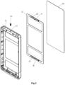
FIG. 1 is a view of a refrigerator door with a replaceable door panel according to the present invention. -
FIG. 2 andFIG 3 are exploded views of the refrigerator door with a replaceable door panel inFIG 1 as viewed from different angles of view. -
FIG. 4 and FIG 5 are respectively enlarged views of dashed region A and dashed region B inFIG 3 . -
FIG. 6 is a view of a button assembly inFIG 2 . -
FIG. 7 is a cross-sectional view of the foam door body inFIG 2 . -
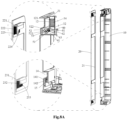
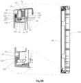
FIG. 8A through FIG 8B are cross-sectional views of the refrigerator door with the replaceable door panel ofFIG 1 during the assembling. -
FIG 8C is a cross-sectional view of the button assembly of the refrigerator door with the replaceable door panel ofFIG 1 when in a pressed state. - The present invention will be described in detail below in combination with embodiments shown in the figures. However, these embodiments do not limit the present invention, and structural or functional changes made by those having ordinary skill in the art according to these embodiments are all included in the protection scope of the present invention.
- As shown in
FIG 1 through FIG 7 , arefrigerator door 100 with a replaceable door panel comprises: afoam door body 10, and adecorative panel 20 detachably connected to thefoam door body 10; a press latch and a limitingmember 141 are disposed on thefoam door body 10; afirst hook 22 and asecond hook 23 opposed to each other are disposed on a rear side of thedecorative panel 20 facing towards thefoam door body 10, alock hole 224 being disposed on thefirst hook 22; when thedecorative panel 20 is assembled to a front side of thefoam door body 10, a front end of the press latch catches thelock hole 224 to limit a displacement of thedecorative panel 20 in an up-down direction; thesecond hook 23 engages the limitingmember 141 to limit the displacement of thedecorative panel 20 in a front-rear direction. - As shown in
FIG 6, FIG 7 andFIG 8B , the press latch comprises abutton assembly 30, afirst locking hook 50 and asecond locking hook 60. When thebutton assembly 30 is in an unpressed state, the first locking hook 50 interlocks with thesecond locking hook 60, and a front end of thefirst locking hook 50 is locked in thelock hole 224; As shown inFIG 6, FIG 7 andFIG 8C , when thebutton assembly 30 is in a pressed state, thesecond locking hook 60 and thefirst locking hook 50 are unlocked, and the front end of thefirst locking hook 50 disengages from thelock hole 224. - Further referring to
FIG 1 through FIG 7 , thefoam door body 10 comprises aperipheral trim strip 11, areceiving hole 12 may be disposed on a side of theperipheral trim strip 11, and thebutton assembly 30 may be received in the receiving hole, wherein thebutton assembly 30 comprises abutton portion 31 and apush rod portion 32, and thebutton portion 31 may be exposed from the receivinghole 12 to facilitate the user to press thebutton portion 31. - In a preferred embodiment, one of a top trim strip and a bottom trim strip of the
peripheral trim strip 11 is provided with thereceiving hole 12, so that the user may release the interlocking relationship between thefirst locking hook 50, thesecond locking hook 60 and thefirst hook 22 by pressing down or up thebutton portion 31, thereby facilitating the detachment of thedecorative panel 20. In the present embodiment, thereceiving hole 12 is disposed in the top trim strip of theperipheral trim strip 11. - As shown in
FIG 6 and FIG 7 , thebutton portion 31 comprises astop 33, which protrudes from a side wall of thebutton portion 31; a receivinggroove 121 is disposed on an inner wall of the receiving hole; wherein thebutton assembly 30 is received in the receivinghole 12, and thestop 33 is received in the receivinggroove 121. - Furthermore, an
elastic member 34 is sleeved outside thepush rod portion 32 of thebutton assembly 30; a resistingportion 122 protrudes from the inner wall of the receivinghole 12, and the resistingportion 122 protrudes toward an interior of thereceiving hole 12; when thebutton assembly 30 is received in thereceiving hole 12, opposite ends of theelastic member 34 elastically abut against thebutton portion 31 and the resistingportion 122, respectively. - In the present embodiment, an end of the
push rod portion 32 away from thebutton portion 31 protrudes from the resistingportion 122 and extends toward thesecond locking hook 60. After thebutton portion 31 is pressed, thepush rod portion 32 moves toward thesecond locking hook 60, and theelastic member 34 is compressed between thebutton portion 31 and the resistingportion 122; after thebutton portion 31 is released, the compressedelastic member 34 extends to provide an elastic force, and thebutton portion 31 and thepush rod portion 32 return from the pressed state to the unpressed state under action of the elastic force. - In addition, during the returning process of the
button portion 31, thestop 33 slides in thereceiving groove 121. After thebutton portion 31 returns, thestop 33 is stopped by an end groove wall (or an upper end groove wall) of the receivinggroove 121 and does not move any more, thereby preventing thebutton portion 31 from ejecting out of the receivinghole 12 after the return and disengaging from the receivinghole 12. - As shown in
FIG 7 , abox 40 is also disposed in thefoam door body 10, and thebox 40 may be integrally formed with theperipheral trim strip 11. Anopening portion 42 is disposed on a side of thebox 40 facing towards thereceiving hole 12, and communicates areceiving space 41 in the interior of thebox 40 with thereceiving hole 12. Thebutton portion 31 is pressed so that thepush rod portion 32 extends through theopening portion 42 into thereceiving space 41 and abuts against alever portion 61 of thesecond locking hook 60. - The
first locking hook 50 and thesecond locking hook 60 that may be interlocked are respectively received in thereceiving space 41 in thebox 40, and thefirst locking hook 50 and thesecond locking hook 60 are pivotally connected to a side wall of thebox 40. - Specifically, a first rotating
shaft 53 is disposed between thefirst locking hook 50 and the side wall of thebox 40, a first torsion spring is disposed on the first rotatingshaft 53, the first torsion spring is sleeved in the first rotatingshaft 53, a fixe end of the torsion spring is fixed to the side wall of thebox 40, and a free end of the torsion spring interacts with thefirst locking hook 50, wherein the first torsion spring provides a torsional force causing thefirst locking hook 50 to rotate around the first rotatingshaft 53. A second rotatingshaft 63 is disposed between thesecond locking hook 60 and the side wall of thebox 40, a second torsion spring is disposed on the second rotatingshaft 63, the second torsion spring is sleeved in the second rotatingshaft 63, a fixed end of the second torsion spring is fixed to the side wall of thebox 40, and a free end of the second torsion spring interacts with thesecond locking hook 60, wherein the second torsion spring provides a torsional force causing thesecond locking hook 60 to rotate around the second rotatingshaft 63, and ahook 61 at a front end of thesecond locking hook 60 catches a hook-catchinggroove 51 at a rear end of thefirst locking hook 50. - In the present embodiment, for example, the torsion force provided by the first torsion spring causes the
first locking hook 50 to rotate clockwise around the first rotatingshaft 53, and then asecond arm 522 of anotched slot 52 at the front end of thefirst locking hook 50 has a tendency to disengage from thelock hole 224; the torsional force provided by the second torsion spring causes thesecond locking hook 60 to rotate counterclockwise around the second rotatingshaft 63, and thehook 61 at the front end of thesecond locking hook 60 has a tendency to catch the hook-catchinggroove 51. - It needs to be appreciated that when the
first hook 22 is not inserted into afirst hook groove 13, the first torsion spring is in a natural state (or a force-not-received state), and the second torsion spring is in a torsional state (or a force-received state). At this time, the torsional force provided by the second torsion spring causes thehook 61 at the front end of thesecond locking hook 60 to have a tendency to catch the hook-catchinggroove 51 at the rear end of thefirst locking hook 50. - In addition, when the
first hook 22 is inserted into thefirst hook groove 13, anextension portion 223 presses against afirst arm portion 521 by using the dead weight of thedecorative panel 20 and theframe 21, the first locking hook 50 pivots around the first rotatingshaft 53, and the first torsion spring is twisted. At this time, thehook 61 smoothly catches the hook-catchinggroove 51 by virtue of a counterclockwise acting force applied by the second torsion spring on thesecond locking hook 60. Thefirst hook 22 is inserted into thefirst hook groove 13; after the front end of thefirst locking hook 50 and thelock hole 224 interlock each other, the torsion force generated by the first torsion spring is smaller than a gravitational force generated by thedecorative panel 20 and theframe 21, to maintain the locked state of thefirst locking hook 50 and thelock hole 224. In addition, since the first locking hook 50 pivots, a direction of the torsional force generated by the first torsion spring is opposite to a direction of a pressing force by which theextension portion 223 of thefirst hook 22 presses against thefirst arm portion 521. - In addition, the
button portion 31 is pressed so that thepush rod portion 32 extends into thereceiving space 41 and pushes against thelever portion 62 at the rear end of thesecond locking hook 60. A pushing force applied by thepush rod portion 32 on thelever portion 62 is greater than the torsional force exerted by the second torsion spring on thesecond locking hook 60. Thesecond locking hook 60 pivots around the secondrotating shaft 63, thehook 61 at the front end of thesecond locking hook 60 is lifted upward, thehook 61 disengages from the hook-catchinggroove 51 at the rear end of thefirst locking hook 50, and thesecond locking hook 60 and thefirst locking hook 50 are unlocked. In the absence of of the constraint of thesecond locking hook 60, the first torsion spring in the counterclockwise torsional state rotates clockwise to return to the natural state, driving thesecond arm portion 522 of the notchedslot 52 at the front end of thefirst locking hook 50 to disengage from thelock hole 224, and thefirst hook 22 and thefirst locking hook 50 are unlocked. Furthermore, the limitation of the displacement of thefirst hook 22 and thefirst locking hook 50 in the up-down direction is released, thefirst hook 22 may be removed from thefirst hook groove 13, and the limitation of the displacement of thedecorative panel 20 and thefoam door body 10 in the up-down direction is also released. - As shown in
FIG 7 ,FIG 8B andFIG 8C , the hook-catchinggroove 51 is disposed at a rear end of thefirst locking hook 50, thehook 61 is disposed at a front end of thesecond locking hook 60, and thelever portion 62 extends at a rear end of thesecond locking hook 60; when thedecorative panel 20 is assembled on the front side of thefoam door body 10, and when thebutton assembly 30 is in the unpressed state, thehook 61 catches the hook-catchinggroove 51, thefirst locking hook 50 interlocks with thesecond locking hook 60, and thefirst locking hook 50 interlocks with thelock hole 224 of thefirst hook 22; when thebutton assembly 30 is in the pressed state, one end of thepush rod portion 32 pushes against thelever portion 62, thehook 62 disengages from the hook-catchinggroove 51, and thefirst locking hook 50 and thesecond locking hook 60 are unlocked. When thebutton assembly 30 is in the pressed state, thepush rod portion 32 pushes against anend face 321 of thelever portion 62 in parallel with thelever portion 62. - As shown in
FIG 3 through FIG 5 , aframe 21 is disposed on a rear side of thedecorative panel 20, and attached and fixed to the rear side of thedecorative panel 20. Theframe 21 comprises afirst hook 22 and asecond hook 23 which are disposed oppositely. In the present embodiment, the structure of thefirst hook 22 is different from the structure of thesecond hook 23, wherein thefirst hook 22 is disposed close an upper end of theframe 21, and thesecond hook 23 is disposed close to a lower end of theframe 21. However, the positions of the first hook and second hook are not limited thereto. In other embodiments of the present invention, the first hook is disposed close to the lower end of the frame, and the second hook is disposed close to the upper end of the frame. - As shown in
FIG. 4 , thefirst hook 22 is formed by bending from the upper end of theframe 21, for example, a sheet metal structure. Thefirst hook 22 comprises a first connectingportion 221 and a firstbent portion 222. Theframe 21 and the firstbent portion 222 are respectively connected to opposite ends of the first connectingportion 221. The firstbent portion 222 is parallel to theframe 21 and thedecorative panel 20. The lower end of the firstbent portion 222 comprises anextension portion 223 which is opposite to thedecorative panel 20 in the front-rear direction, that is, theextension portion 223 is parallel to and opposite to thedecorative panel 20, and thelock hole 224 is disposed on theextension portion 223. - As shown in
FIG. 7 andFIG. 8A , corresponding to thefirst hook 22, thefirst hook groove 13 is disposed on the front side of thefoam door body 10. In one embodiment, thefirst hook groove 13 may be formed on theperipheral trim strip 11. In the present embodiment, thebox 40 is disposed at the bottom of thefirst hook groove 13. The interior of thefirst hook groove 13 is communicated with the openingportion 42 of thebox 40. - With reference to
FIG 8A through FIG 8B , when thefirst hook 22 is mounted in thefirst hook groove 13, thefirst hook 22 is inserted into thefirst hook groove 13 and moves towards the bottom of thefirst hook groove 13 in the up-down direction. Theextension portion 223 of thefirst hook 22 is inserted through the openingportion 42 into the receivingspace 41, theextension portion 223 presses down against afirst slot wall 521 of the notchedslot 52 at the front end of thefirst locking hook 50, thefirst locking hook 50 pivots, asecond slot wall 522 of the notchedslot 51 catches thelock hole 224, and thefirst hook 22 and thefirst locking hook 50 snap-fit each other, thereby limiting the displacement of thefirst hook 22 in the up-down direction, and further limiting the displacement of thedecorative panel 20 in the up-down direction. - As shown in
FIG. 3 ,FIG. 5 ,FIG. 7 andFIG 8B , the rear side of theframe 21 further comprises asecond hook 23, thesecond hook 23 comprises a second connectingportion 231 and a secondbent portion 232, the lower end of theframe 21 and the secondbent portion 232 are respectively disposed at opposite ends of the second connectingportion 231, and the secondbent portion 232 is parallel and opposite to thedecorative panel 20. - Corresponding to the
second hook 23, the bottom trim strip of theperipheral trim strip 11 of thefoam door body 10 is provided with asecond hook groove 14, astopper 141 is disposed at an opening on a front side of thesecond hook groove 14, and a rear side of thestopper 141 comprises an elastic resistingportion 142. - When the
second hook 23 is inserted into thesecond hook groove 14, the elastic resistingportion 142 elastically pushes the secondbent portion 232 in the front-rear direction. Preferably, the elastic resistingportion 142 elastically pushes the secondbent portion 232 backward in thesecond hook groove 14, so that thedecorative panel 20 fits on the front side of thefoam door body 10. There is no gap between thedecorative panel 20 and thefoam door body 10, so that a more beautiful appearance is presented. - In a preferred embodiment, one end of the elastic resisting
portion 142 is connected to a top end of thestopper 141, the other end of the elastic resistingportion 142 is suspended at the lower end of thestopper 141, and the elastic resistingportion 142 extends obliquely downward along a top end of thestopper 141 towards a rear groove wall of thesecond hook groove 14. - As shown in
FIG. 8A , the rear groove wall of thesecond hook groove 14 is disposed opposite to thestopper 141, apositioning bump 15 is disposed on the rear groove wall, apositioning recess 233 is disposed on the secondbent portion 223, wherein thesecond hook 23 catches thesecond hook groove 14, and under the elastic pushing of the elastic resistingportion 142, thepositioning recess 233 and thepositioning bump 15 snap-fit each other, thereby limiting the displacement of thesecond hook 23 in the left-right direction, so that thesecond hook 23 is engaged in thesecond hook groove 14 more stably. - In addition, in the present embodiment, the
first hook 22 is provided with reinforcingribs 225, and thesecond hook 23 is provided with reinforcingribs 234, wherein the reinforcingribs - As shown in
FIG. 8A andFIG 8B , the assembling process of therefrigerator door 100 with a replaceable door panel roughly comprises: allowing thefirst hook 22 and thesecond hook 23 of theframe 21 at the rear side of thedecorative panel 20 to catch the correspondingfirst hook groove 13 and thesecond hook groove 14, respectively. - The engagement process of the
first hook 22 and thefirst hook groove 13 is as follows: theextension portion 223 of thefirst hook 22 presses against thefirst arm portion 521 at the front end of thefirst locking hook 50, thefirst locking hook 50 pivots, thesecond arm portion 522 at the front end of thefirst locking hook 22 catches the lock hole on theextension portion 223, and thefirst locking hook 50 is locked with thefirst hook 22; thefirst locking hook 50 pivots, the hook-catchinggroove 51 at the rear end of thefirst locking hook 50 engages with thehook 61 at the front end of thesecond locking hook 60, and thefirst locking hook 50 is locked with thesecond locking hook 60; - The engagement process of the
second hook 23 and thesecond hook groove 14 is as follows: thesecond hook 23 is inserted into thesecond hook groove 14, and pushes thedecorative panel 20 to move towards the rear side of thesecond hook groove 14, thesecond hook 23 falls into the bottom of thesecond hook groove 14, and the elastic resistingportion 142 at the rear side of thestopper 141 elastically pushes against the secondbent portion 232 of thesecond hook 23. - As shown in
FIG 8C , a process of detaching thedecorative panel 20 and thefoam door body 10 roughly comprises:
First, thebutton portion 31 is pushed, thepush rod portion 32 pushes against thelever portion 62 at the rear end of thesecond locking hook 60, thesecond locking hook 60 pivots around the secondrotating shaft 63, thehook 62 at the front end of thesecond locking hook 60 disengages from the hook-catchinggroove 51 at the rear end of thefirst locking hook 50, and the interlocking of thesecond locking hook 60 and thefirst locking hook 50 is released; At this time, thefirst locking hook 50 pivots under the action of the first torsion spring, thesecond arm portion 522 of the notchedslot 52 at the front end of thefirst locking hook 50 disengages from thelock hole 224 of thefirst hook 22, and thefirst hook 22 and thefirst locking hook 50 are unlocked; Next, thedecorative panel 10 is moved in the up-down direction, thefirst hook 22 disengages from thefirst insertion groove 13, thesecond hook 23 disengages from thesecond insertion groove 14, and thedecorative panel 20 is removed from the front side of thefoam door body 10. - To sum up, the invention provides a decorative panel with a replaceable door panel. With the latch assembly and the stopper in the foam door body engaging the two differently-structured hooks on the rear side of the decorative panel respectively, the displacement of the decorative panel in the up-down direction and front-rear direction is limited simultaneously; since screws are not used for fixation, and instead the simple engagement structures are employed, the assembling between the decorative panel and the foam door body is stabler, the risk of the breakage of the decorative panel is smaller, and meanwhile the detachment is simpler and more convenient.
- It should be understood that although the description is described according to the embodiments, not every embodiment only comprises one independent technical solution, that such a description manner is only for the sake of clarity, that those skilled in the art should take the description as an integral part, and that the technical solutions in the embodiments may be suitably combined to form other embodiments understandable by those skilled in the art.
- The detailed descriptions set forth above are merely specific illustrations of feasible embodiments of the present invention, and are not intended to limit the scope of protection of the present invention. All equivalent embodiments or modifications that do not depart from the art spirit of the present invention should fall within the scope of protection of the present invention.
Claims (12)
- A refrigerator door with a replaceable door panel, wherein the refrigerator door comprises:a foam door body, and a decorative panel detachably connected to the foam door body;a press latch and a limiting member are disposed on the foam door body;a first hook and a second hook opposed to each other are disposed on a rear side of the decorative panel facing towards the foam door body, a lock hole being disposed on the first hook;wherein when the decorative panel is assembled to a front side of the foam door body, a front end of the press latch catches the lock hole to limit a displacement of the decorative panel in an up-down direction; the second hook engages the limiting member to limit a displacement of the decorative panel in a front-rear direction.
- The refrigerator door with a replaceable door panel according to claim 1, wherein the press latch comprises a button assembly, a first locking hook and a second locking hook, wherein when the button assembly is in an unpressed state, the first locking hook interlocks with the second locking hook, and a front end of the first locking hook is locked in the lock hole.
- The refrigerator door with a replaceable door panel according to claim 2, wherein when the button assembly is in a pressed state, the second locking hook and the first locking hook are unlocked, and the front end of the first locking hook disengages from the lock hole.
- The refrigerator door with a replaceable door panel according to claim 2, wherein the foam door body comprises a peripheral trim strip, a receiving hole is disposed in the peripheral trim strip, and the button assembly is received in the receiving hole; wherein the button assembly comprises a button portion and a push rod portion, and the button portion is exposed from the receiving hole.
- The refrigerator door with a replaceable door panel according to claim 4, wherein the button portion comprises a stop, a receiving groove is disposed in the receiving hole, wherein when the button assembly is in the unpressed state, the stop is received in the receiving groove.
- The refrigerator door with a replaceable door panel according to claim 4, wherein the button assembly comprises an elastic member, the elastic member is sleeved outside the push rod portion and received in the receiving hole, wherein a resisting portion protrudes from an interior of the receiving hole, and opposite ends of the elastic member elastically abut against the button portion and the resisting portion, respectively.
- The refrigerator door with a replaceable door panel according to claim 4, wherein a box is also disposed in the foam door body, an opening portion is disposed on a side of the box facing towards the receiving hole, the opening portion is communicated with the receiving hole, and the first locking hook and the second locking hook are assembled in a receiving space in an interior of the box.
- The refrigerator door with a replaceable door panel according to claim 7, wherein a lower end of the first hook comprises an extension portion which is opposite to the decorative panel in the front-rear direction, and the lock hole is disposed on the extension portion; wherein the hook is inserted through the opening portion into the receiving space in the up-down direction, and the lock hole is locked with the front end of the first locking hook.
- The refrigerator door with a replaceable door panel according to claim 4, wherein a hook-catching groove is disposed at a rear end of the first locking hook, a hook is disposed at a front end of the second locking hook, and a lever portion extends at a rear end of the second locking hook; when the button assembly is in the unpressed state, the hook catches the hook-catching groove, and the first locking hook interlocks with the second locking hook; when the button assembly is in the pressed state, the push rod portion pushes against the lever portion, the hook disengages from the hook-catching groove, and the first locking hook and the second locking hook are unlocked.
- The refrigerator door with a replaceable door panel according to claim 9, wherein when the button assembly is in the pressed state, the push rod portion pushes against an end face of the lever portion in parallel with the lever portion.
- The refrigerator door with a replaceable door panel according to claim 9, wherein a front end of the first locking hook comprises a notched slot, the notched slot has opposite first slot wall and second slot wall, wherein the hook pushes down the first slot wall, and the second slot wall catches the lock hole.
- The refrigerator door with a replaceable door panel according to claim 11, wherein a first rotating shaft is disposed between the first locking hook and a side wall of the box in the foam door body, a first torsion spring is disposed on the first rotating shaft, wherein the first torsion spring drives the first locking hook to rotate about the first rotating shaft, and the second slot wall disengages from the lock hole; and a second rotating shaft is disposed between the second locking hook and the box, a second torsion spring is disposed on the second rotating shaft, the second torsion spring drives the second locking hook to rotate about the second rotating shaft, and the hook catches the hook-catching groove.
Applications Claiming Priority (2)
| Application Number | Priority Date | Filing Date | Title |
|---|---|---|---|
| CN202010623430.4A CN113865235B (en) | 2020-06-30 | 2020-06-30 | Refrigerator doors with replaceable fronts |
| PCT/CN2021/100880 WO2022001697A1 (en) | 2020-06-30 | 2021-06-18 | Refrigerator door with replaceable door face |
Publications (3)
| Publication Number | Publication Date |
|---|---|
| EP4174419A1 true EP4174419A1 (en) | 2023-05-03 |
| EP4174419A4 EP4174419A4 (en) | 2023-11-29 |
| EP4174419B1 EP4174419B1 (en) | 2026-01-07 |
Family
ID=78981987
Family Applications (1)
| Application Number | Title | Priority Date | Filing Date |
|---|---|---|---|
| EP21833480.3A Active EP4174419B1 (en) | 2020-06-30 | 2021-06-18 | Refrigerator door with a replaceable door panel |
Country Status (4)
| Country | Link |
|---|---|
| US (1) | US12449184B1 (en) |
| EP (1) | EP4174419B1 (en) |
| CN (1) | CN113865235B (en) |
| WO (1) | WO2022001697A1 (en) |
Families Citing this family (10)
| Publication number | Priority date | Publication date | Assignee | Title |
|---|---|---|---|---|
| EP4051066B1 (en) * | 2019-10-31 | 2025-12-24 | Kimberly-Clark Worldwide, Inc. | Dispensing device with replaceable front cover |
| CN113865235B (en) * | 2020-06-30 | 2023-02-17 | 青岛海尔电冰箱有限公司 | Refrigerator doors with replaceable fronts |
| CN114076479A (en) * | 2020-08-10 | 2022-02-22 | 青岛海尔特种电冰箱有限公司 | Refrigerator door with replaceable door face |
| USD1075858S1 (en) * | 2021-08-26 | 2025-05-20 | Jinlong Lin | Refrigerator door |
| CN116659151B (en) * | 2022-02-18 | 2026-01-30 | 青岛海尔电冰箱有限公司 | refrigerator |
| CN115900209A (en) * | 2022-11-25 | 2023-04-04 | 澳柯玛股份有限公司 | A push-to-open type fully-sealed fresh-keeping box |
| CN116086110B (en) * | 2023-02-01 | 2024-08-30 | 长虹美菱股份有限公司 | Quick-change panel of refrigerator door body and replacement method |
| CN116379691A (en) * | 2023-05-04 | 2023-07-04 | 长虹美菱股份有限公司 | Refrigerator door structure and refrigerator |
| CN116734554B (en) * | 2023-07-06 | 2025-09-16 | 海信冰箱有限公司 | Refrigerator door and refrigerator |
| CN117781572A (en) * | 2023-12-01 | 2024-03-29 | 长虹美菱股份有限公司 | Refrigerator door quick change panel and refrigerator |
Family Cites Families (67)
| Publication number | Priority date | Publication date | Assignee | Title |
|---|---|---|---|---|
| US3402578A (en) * | 1967-02-06 | 1968-09-24 | Long Mfg Company Inc | Pushbutton latch and lock mechanism |
| US3642164A (en) * | 1970-07-31 | 1972-02-15 | Vendo Co | Insulated cabinet construction for vending machines or the like |
| US3708997A (en) * | 1970-12-07 | 1973-01-09 | American Formed Plastics Corp | Refrigerator structure |
| DE2922384C2 (en) * | 1979-06-01 | 1984-02-23 | Bosch-Siemens Hausgeräte GmbH, 7000 Stuttgart | A built-in device, in particular a refrigerator or freezer, which can be used in a built-in niche of a tall kitchen cabinet or the like |
| US5007226A (en) * | 1989-05-01 | 1991-04-16 | Soltech, Inc. | Insulated refrigerator door construction |
| DE4334761A1 (en) * | 1993-10-12 | 1995-04-13 | Bosch Siemens Hausgeraete | Household appliance for installation in a furniture niche in a kitchenette or the like |
| DE19840416A1 (en) * | 1998-09-04 | 2000-03-09 | Bsh Bosch Siemens Hausgeraete | Refrigerator |
| CN2447706Y (en) * | 2000-10-19 | 2001-09-12 | 陈安军 | Refrigerator with transparent cover and moving door |
| JP3394524B2 (en) * | 2000-12-01 | 2003-04-07 | 三菱電機株式会社 | Refrigerator door and method of manufacturing refrigerator door |
| KR100518412B1 (en) * | 2003-03-19 | 2005-09-29 | 엘지전자 주식회사 | Structure for holding leftover water from a refrigerator dispenser |
| JP2006046793A (en) * | 2004-08-04 | 2006-02-16 | Matsushita Electric Ind Co Ltd | Refrigerator door |
| KR100577373B1 (en) * | 2004-10-25 | 2006-05-10 | 위니아만도 주식회사 | Decorative panel fastening structure of Kimchi storage |
| MX2007011420A (en) * | 2005-03-16 | 2007-10-12 | Lg Electronics Inc | Damper embedded in a home bar door of a refrigerator and method for manufacturing the same. |
| DE102005021607A1 (en) * | 2005-05-10 | 2006-11-23 | BSH Bosch und Siemens Hausgeräte GmbH | Door for a household appliance |
| US7942013B2 (en) * | 2006-01-03 | 2011-05-17 | Lg Electronics Inc. | Display for refrigerator and display mounting frame, display mounting structure comprising the same |
| US7770985B2 (en) * | 2006-02-15 | 2010-08-10 | Maytag Corporation | Kitchen appliance having floating glass panel |
| CN101131282A (en) * | 2006-08-22 | 2008-02-27 | 泰州乐金电子冷机有限公司 | Family pub for refrigerator |
| CN101131291B (en) * | 2006-08-22 | 2011-03-30 | 泰州乐金电子冷机有限公司 | Family pub for refrigerator |
| US7665810B2 (en) * | 2007-04-10 | 2010-02-23 | Maytag Corporation | Kitchen appliance having a floating glass panel |
| KR101350025B1 (en) * | 2007-06-05 | 2014-01-13 | 엘지전자 주식회사 | Home bar for refrigerator |
| KR101357339B1 (en) * | 2007-06-20 | 2014-02-03 | 엘지전자 주식회사 | Home bar for refrigerator |
| KR100877989B1 (en) * | 2007-11-15 | 2009-01-12 | 엘지전자 주식회사 | Refrigerator Door |
| KR101576672B1 (en) * | 2008-02-21 | 2015-12-10 | 엘지전자 주식회사 | Refrigerator and refrigerator door |
| KR100949288B1 (en) * | 2008-04-02 | 2010-03-25 | 엘지전자 주식회사 | Refrigerator door |
| EP2313721B1 (en) * | 2008-08-20 | 2019-06-05 | LG Electronics Inc. | Refrigerator and method of fabricating the same |
| KR101602223B1 (en) * | 2009-05-22 | 2016-03-10 | 엘지전자 주식회사 | Decorative panel and refrigerator with it |
| KR20110042786A (en) * | 2009-10-20 | 2011-04-27 | 삼성전자주식회사 | Method of manufacturing refrigerators and freezers |
| IT1399435B1 (en) * | 2010-04-13 | 2013-04-19 | Gatto S P A | DOOR FOR FURNITURE WITH REMOVABLE PANEL - INTERCHANGEABLE. |
| KR101752670B1 (en) * | 2010-08-11 | 2017-07-03 | 삼성전자주식회사 | Refrigerator |
| CN103201230B (en) * | 2010-09-14 | 2016-07-13 | 康宁股份有限公司 | Electric pallet and its installation |
| CN102620503A (en) * | 2011-01-28 | 2012-08-01 | 泰州乐金电子冷机有限公司 | Refrigerator door and refrigerator with same |
| DE102011109904A1 (en) * | 2011-02-03 | 2012-08-09 | Liebherr-Hausgeräte Ochsenhausen GmbH | household appliance |
| EP3508804B1 (en) * | 2011-08-05 | 2023-03-01 | LG Electronics Inc. | Refrigerator with inner door |
| CN102384627B (en) * | 2011-12-22 | 2014-01-15 | 合肥美的电冰箱有限公司 | Door body used for refrigerator and refrigerator with door body |
| KR102001134B1 (en) * | 2012-06-01 | 2019-07-17 | 엘지전자 주식회사 | Door for a refrigerator and method for manufacturing the same, decoration panel, method and apparatus for processing a transparent synthetic resine panel |
| JP5488747B2 (en) * | 2012-08-06 | 2014-05-14 | パナソニック株式会社 | refrigerator |
| CN102980356A (en) * | 2012-12-05 | 2013-03-20 | 合肥华凌股份有限公司 | Top cover structure for refrigeration equipment and refrigeration equipment with same |
| CN103499176B (en) * | 2013-09-30 | 2016-01-13 | 合肥华凌股份有限公司 | For top cover and the refrigerating plant with this top cover of refrigerating plant |
| CN104279821B (en) * | 2014-10-15 | 2016-08-17 | 合肥美的电冰箱有限公司 | Refrigerator door structure and refrigerator |
| KR101677334B1 (en) * | 2014-10-24 | 2016-11-17 | 엘지전자 주식회사 | Refrigerator door |
| KR101659180B1 (en) * | 2014-12-22 | 2016-09-22 | 엘지전자 주식회사 | Tuch sensor assembly and refrigerator door with Tuch sensor assembly |
| CN104457115B (en) * | 2014-12-23 | 2016-11-30 | 合肥美的电冰箱有限公司 | refrigerator door and refrigerator |
| US9435579B1 (en) * | 2015-04-10 | 2016-09-06 | Electrolux Home Products, Inc. | Insulated door assembly |
| KR102601889B1 (en) * | 2016-12-12 | 2023-11-15 | 엘지전자 주식회사 | Refrigerator |
| KR102602658B1 (en) * | 2016-12-12 | 2023-11-16 | 엘지전자 주식회사 | Refrigerator |
| KR102273092B1 (en) * | 2016-12-12 | 2021-07-06 | 엘지전자 주식회사 | Refrigerator |
| KR102828393B1 (en) * | 2016-12-15 | 2025-07-02 | 삼성전자주식회사 | Refrigerator |
| CN206420220U (en) * | 2016-12-30 | 2017-08-18 | 广东格兰仕集团有限公司 | The assembling structure of refrigerator door |
| KR102259753B1 (en) * | 2017-03-24 | 2021-06-02 | 엘지전자 주식회사 | Refrigerator |
| EP3378360B1 (en) * | 2017-03-24 | 2022-07-27 | LG Electronics Inc. | Refrigerator |
| CN107187349B (en) * | 2017-07-17 | 2023-02-03 | 联扬塑胶(深圳)有限公司 | Child safety seat attachment mechanism |
| CN207763338U (en) * | 2017-12-22 | 2018-08-24 | Tcl家用电器(合肥)有限公司 | Refrigerator doors and refrigerator |
| KR102574759B1 (en) * | 2018-10-23 | 2023-09-06 | 주식회사 위니아 | Assembling structure of Refrigerator door |
| WO2020213861A1 (en) * | 2019-04-15 | 2020-10-22 | Samsung Electronics Co., Ltd. | Refrigerator |
| KR102312667B1 (en) * | 2019-04-15 | 2021-10-15 | 삼성전자주식회사 | Refrigerator |
| CN210119057U (en) * | 2019-05-30 | 2020-02-28 | 青岛海信电子技术服务有限公司 | A kind of refrigerator |
| US10823483B1 (en) * | 2019-10-15 | 2020-11-03 | Haier Us Appliance Solutions, Inc. | Refrigerator appliance with heat transfer features for reducing condensation |
| CN113865235B (en) * | 2020-06-30 | 2023-02-17 | 青岛海尔电冰箱有限公司 | Refrigerator doors with replaceable fronts |
| CN113865231B (en) * | 2020-06-30 | 2023-07-14 | 青岛海尔电冰箱有限公司 | Refrigerator doors with replaceable fronts |
| CN113865182B (en) * | 2020-06-30 | 2023-02-03 | 青岛海尔电冰箱有限公司 | Refrigerator doors with replaceable fronts |
| CN113865236B (en) * | 2020-06-30 | 2023-02-17 | 青岛海尔电冰箱有限公司 | Refrigerator doors with replaceable fronts |
| CN113865237B (en) * | 2020-06-30 | 2023-01-20 | 青岛海尔电冰箱有限公司 | Refrigerator door with replaceable door face |
| CN113865234B (en) * | 2020-06-30 | 2022-11-29 | 青岛海尔电冰箱有限公司 | Refrigerator door with replaceable door face |
| CN113865232B (en) * | 2020-06-30 | 2022-07-26 | 青岛海尔电冰箱有限公司 | Refrigerator door with replaceable door face |
| CN113865233A (en) * | 2020-06-30 | 2021-12-31 | 青岛海尔电冰箱有限公司 | Refrigerator door with replaceable door face |
| CN114076480B (en) * | 2020-08-10 | 2023-01-20 | 青岛海尔特种电冰箱有限公司 | Refrigerator door with replaceable door face |
| CN114076479A (en) * | 2020-08-10 | 2022-02-22 | 青岛海尔特种电冰箱有限公司 | Refrigerator door with replaceable door face |
-
2020
- 2020-06-30 CN CN202010623430.4A patent/CN113865235B/en active Active
-
2021
- 2021-06-18 EP EP21833480.3A patent/EP4174419B1/en active Active
- 2021-06-18 US US18/013,226 patent/US12449184B1/en active Active
- 2021-06-18 WO PCT/CN2021/100880 patent/WO2022001697A1/en not_active Ceased
Also Published As
| Publication number | Publication date |
|---|---|
| EP4174419B1 (en) | 2026-01-07 |
| WO2022001697A1 (en) | 2022-01-06 |
| CN113865235B (en) | 2023-02-17 |
| CN113865235A (en) | 2021-12-31 |
| US12449184B1 (en) | 2025-10-21 |
| EP4174419A4 (en) | 2023-11-29 |
| US20230251024A1 (en) | 2023-08-10 |
Similar Documents
| Publication | Publication Date | Title |
|---|---|---|
| US12449184B1 (en) | Refrigerator door with replaceable door panel | |
| EP4174408B1 (en) | Refrigerator door with a replaceable door panel | |
| US12123639B2 (en) | Refrigerator door with replaceable door panel | |
| EP4174418B1 (en) | Refrigerator door with a replaceable door panel | |
| US12339054B2 (en) | Refrigerator door with replaceable door panel | |
| US12292227B2 (en) | Refrigerator door with replaceable door panel | |
| EP4174417B1 (en) | Refrigerator door with a replaceable door panel | |
| CN220247839U (en) | Lock body and lock | |
| CN208310494U (en) | Locking devicen | |
| TWM649551U (en) | Latch device and latch system | |
| CN209219337U (en) | By formula bracelet | |
| CN220327284U (en) | Lock hook structure and cooking utensil having the same | |
| JP6951604B1 (en) | Housing mounting structure | |
| CN216844830U (en) | Integrated kitchen | |
| CN217420831U (en) | Dishwasher door lock mechanism and dishwasher | |
| CN219396520U (en) | Multiplexing cutlery box | |
| CN113700394B (en) | Door lock and cooking machine with the door lock | |
| CN219699211U (en) | Adjustable anti-hooking wrist writing corrector | |
| CN220212760U (en) | Buckling structure and eggbeater | |
| CN218137962U (en) | Buckle tool | |
| CN111688448A (en) | Modular cover locking device of object shielding curtain |
Legal Events
| Date | Code | Title | Description |
|---|---|---|---|
| STAA | Information on the status of an ep patent application or granted ep patent |
Free format text: STATUS: THE INTERNATIONAL PUBLICATION HAS BEEN MADE |
|
| PUAI | Public reference made under article 153(3) epc to a published international application that has entered the european phase |
Free format text: ORIGINAL CODE: 0009012 |
|
| STAA | Information on the status of an ep patent application or granted ep patent |
Free format text: STATUS: REQUEST FOR EXAMINATION WAS MADE |
|
| 17P | Request for examination filed |
Effective date: 20221228 |
|
| AK | Designated contracting states |
Kind code of ref document: A1 Designated state(s): AL AT BE BG CH CY CZ DE DK EE ES FI FR GB GR HR HU IE IS IT LI LT LU LV MC MK MT NL NO PL PT RO RS SE SI SK SM TR |
|
| DAV | Request for validation of the european patent (deleted) | ||
| DAX | Request for extension of the european patent (deleted) | ||
| A4 | Supplementary search report drawn up and despatched |
Effective date: 20231026 |
|
| RIC1 | Information provided on ipc code assigned before grant |
Ipc: E05B 1/00 20060101ALI20231020BHEP Ipc: F25D 23/02 20060101AFI20231020BHEP |
|
| RIC1 | Information provided on ipc code assigned before grant |
Ipc: F25D 23/02 20060101AFI20250616BHEP |
|
| GRAP | Despatch of communication of intention to grant a patent |
Free format text: ORIGINAL CODE: EPIDOSNIGR1 |
|
| STAA | Information on the status of an ep patent application or granted ep patent |
Free format text: STATUS: GRANT OF PATENT IS INTENDED |
|
| INTG | Intention to grant announced |
Effective date: 20250729 |
|
| GRAS | Grant fee paid |
Free format text: ORIGINAL CODE: EPIDOSNIGR3 |
|
| GRAA | (expected) grant |
Free format text: ORIGINAL CODE: 0009210 |
|
| STAA | Information on the status of an ep patent application or granted ep patent |
Free format text: STATUS: THE PATENT HAS BEEN GRANTED |
|
| RAP3 | Party data changed (applicant data changed or rights of an application transferred) |
Owner name: CHONGQING HAIER REFRIGERATION ELECTRIC APPLIANCECO., LTD. Owner name: QINGDAO HAIER REFRIGERATOR CO., LTD Owner name: HAIER SMART HOME CO., LTD. |
|
| AK | Designated contracting states |
Kind code of ref document: B1 Designated state(s): AL AT BE BG CH CY CZ DE DK EE ES FI FR GB GR HR HU IE IS IT LI LT LU LV MC MK MT NL NO PL PT RO RS SE SI SK SM TR |
|
| REG | Reference to a national code |
Ref country code: CH Ref legal event code: F10 Free format text: ST27 STATUS EVENT CODE: U-0-0-F10-F00 (AS PROVIDED BY THE NATIONAL OFFICE) Effective date: 20260107 Ref country code: GB Ref legal event code: FG4D |
|
| REG | Reference to a national code |
Ref country code: DE Ref legal event code: R096 Ref document number: 602021046094 Country of ref document: DE |
|
| REG | Reference to a national code |
Ref country code: IE Ref legal event code: FG4D |
|
| REG | Reference to a national code |
Ref country code: NL Ref legal event code: MP Effective date: 20260107 |
|
| PG25 | Lapsed in a contracting state [announced via postgrant information from national office to epo] |
Ref country code: NL Free format text: LAPSE BECAUSE OF FAILURE TO SUBMIT A TRANSLATION OF THE DESCRIPTION OR TO PAY THE FEE WITHIN THE PRESCRIBED TIME-LIMIT Effective date: 20260107 |
|
| REG | Reference to a national code |
Ref country code: AT Ref legal event code: MK05 Ref document number: 1875832 Country of ref document: AT Kind code of ref document: T Effective date: 20260107 |
|
| PG25 | Lapsed in a contracting state [announced via postgrant information from national office to epo] |
Ref country code: RS Free format text: LAPSE BECAUSE OF FAILURE TO SUBMIT A TRANSLATION OF THE DESCRIPTION OR TO PAY THE FEE WITHIN THE PRESCRIBED TIME-LIMIT Effective date: 20260407 |
|
| PG25 | Lapsed in a contracting state [announced via postgrant information from national office to epo] |
Ref country code: ES Free format text: LAPSE BECAUSE OF FAILURE TO SUBMIT A TRANSLATION OF THE DESCRIPTION OR TO PAY THE FEE WITHIN THE PRESCRIBED TIME-LIMIT Effective date: 20260107 |
|
| PG25 | Lapsed in a contracting state [announced via postgrant information from national office to epo] |
Ref country code: PL Free format text: LAPSE BECAUSE OF FAILURE TO SUBMIT A TRANSLATION OF THE DESCRIPTION OR TO PAY THE FEE WITHIN THE PRESCRIBED TIME-LIMIT Effective date: 20260107 |
|
| PG25 | Lapsed in a contracting state [announced via postgrant information from national office to epo] |
Ref country code: GR Free format text: LAPSE BECAUSE OF FAILURE TO SUBMIT A TRANSLATION OF THE DESCRIPTION OR TO PAY THE FEE WITHIN THE PRESCRIBED TIME-LIMIT Effective date: 20260408 |
|
| REG | Reference to a national code |
Ref country code: LT Ref legal event code: MG9D |
|
| PG25 | Lapsed in a contracting state [announced via postgrant information from national office to epo] |
Ref country code: LT Free format text: LAPSE BECAUSE OF FAILURE TO SUBMIT A TRANSLATION OF THE DESCRIPTION OR TO PAY THE FEE WITHIN THE PRESCRIBED TIME-LIMIT Effective date: 20260107 |
|
| PGFP | Annual fee paid to national office [announced via postgrant information from national office to epo] |
Ref country code: DE Payment date: 20260612 Year of fee payment: 6 |
|
| PG25 | Lapsed in a contracting state [announced via postgrant information from national office to epo] |
Ref country code: NO Free format text: LAPSE BECAUSE OF FAILURE TO SUBMIT A TRANSLATION OF THE DESCRIPTION OR TO PAY THE FEE WITHIN THE PRESCRIBED TIME-LIMIT Effective date: 20260407 |
|
| PG25 | Lapsed in a contracting state [announced via postgrant information from national office to epo] |
Ref country code: FI Free format text: LAPSE BECAUSE OF FAILURE TO SUBMIT A TRANSLATION OF THE DESCRIPTION OR TO PAY THE FEE WITHIN THE PRESCRIBED TIME-LIMIT Effective date: 20260107 Ref country code: AT Free format text: LAPSE BECAUSE OF FAILURE TO SUBMIT A TRANSLATION OF THE DESCRIPTION OR TO PAY THE FEE WITHIN THE PRESCRIBED TIME-LIMIT Effective date: 20260107 Ref country code: SE Free format text: LAPSE BECAUSE OF FAILURE TO SUBMIT A TRANSLATION OF THE DESCRIPTION OR TO PAY THE FEE WITHIN THE PRESCRIBED TIME-LIMIT Effective date: 20260107 |
|
| PG25 | Lapsed in a contracting state [announced via postgrant information from national office to epo] |
Ref country code: HR Free format text: LAPSE BECAUSE OF FAILURE TO SUBMIT A TRANSLATION OF THE DESCRIPTION OR TO PAY THE FEE WITHIN THE PRESCRIBED TIME-LIMIT Effective date: 20260107 |
|
| PG25 | Lapsed in a contracting state [announced via postgrant information from national office to epo] |
Ref country code: PT Free format text: LAPSE BECAUSE OF FAILURE TO SUBMIT A TRANSLATION OF THE DESCRIPTION OR TO PAY THE FEE WITHIN THE PRESCRIBED TIME-LIMIT Effective date: 20260507 Ref country code: IS Free format text: LAPSE BECAUSE OF FAILURE TO SUBMIT A TRANSLATION OF THE DESCRIPTION OR TO PAY THE FEE WITHIN THE PRESCRIBED TIME-LIMIT Effective date: 20260507 |
|
| PG25 | Lapsed in a contracting state [announced via postgrant information from national office to epo] |
Ref country code: LV Free format text: LAPSE BECAUSE OF FAILURE TO SUBMIT A TRANSLATION OF THE DESCRIPTION OR TO PAY THE FEE WITHIN THE PRESCRIBED TIME-LIMIT Effective date: 20260107 |
|
| PG25 | Lapsed in a contracting state [announced via postgrant information from national office to epo] |
Ref country code: BG Free format text: LAPSE BECAUSE OF FAILURE TO SUBMIT A TRANSLATION OF THE DESCRIPTION OR TO PAY THE FEE WITHIN THE PRESCRIBED TIME-LIMIT Effective date: 20260107 |