EP4174416A1 - Refrigerator door having replaceable door surface - Google Patents
Refrigerator door having replaceable door surface Download PDFInfo
- Publication number
- EP4174416A1 EP4174416A1 EP21832151.1A EP21832151A EP4174416A1 EP 4174416 A1 EP4174416 A1 EP 4174416A1 EP 21832151 A EP21832151 A EP 21832151A EP 4174416 A1 EP4174416 A1 EP 4174416A1
- Authority
- EP
- European Patent Office
- Prior art keywords
- door
- front panel
- frame
- replaceable
- foam
- Prior art date
- Legal status (The legal status is an assumption and is not a legal conclusion. Google has not performed a legal analysis and makes no representation as to the accuracy of the status listed.)
- Granted
Links
Images



Classifications
-
- F—MECHANICAL ENGINEERING; LIGHTING; HEATING; WEAPONS; BLASTING
- F25—REFRIGERATION OR COOLING; COMBINED HEATING AND REFRIGERATION SYSTEMS; HEAT PUMP SYSTEMS; MANUFACTURE OR STORAGE OF ICE; LIQUEFACTION SOLIDIFICATION OF GASES
- F25D—REFRIGERATORS; COLD ROOMS; ICE-BOXES; COOLING OR FREEZING APPARATUS NOT OTHERWISE PROVIDED FOR
- F25D23/00—General constructional features
- F25D23/02—Doors; Covers
-
- E—FIXED CONSTRUCTIONS
- E05—LOCKS; KEYS; WINDOW OR DOOR FITTINGS; SAFES
- E05C—BOLTS OR FASTENING DEVICES FOR WINGS, SPECIALLY FOR DOORS OR WINDOWS
- E05C19/00—Other devices specially designed for securing wings, e.g. with suction cups
- E05C19/16—Devices holding the wing by magnetic or electromagnetic attraction
- E05C19/161—Devices holding the wing by magnetic or electromagnetic attraction magnetic gaskets
-
- F—MECHANICAL ENGINEERING; LIGHTING; HEATING; WEAPONS; BLASTING
- F25—REFRIGERATION OR COOLING; COMBINED HEATING AND REFRIGERATION SYSTEMS; HEAT PUMP SYSTEMS; MANUFACTURE OR STORAGE OF ICE; LIQUEFACTION SOLIDIFICATION OF GASES
- F25D—REFRIGERATORS; COLD ROOMS; ICE-BOXES; COOLING OR FREEZING APPARATUS NOT OTHERWISE PROVIDED FOR
- F25D23/00—General constructional features
- F25D23/02—Doors; Covers
- F25D23/028—Details
-
- F—MECHANICAL ENGINEERING; LIGHTING; HEATING; WEAPONS; BLASTING
- F25—REFRIGERATION OR COOLING; COMBINED HEATING AND REFRIGERATION SYSTEMS; HEAT PUMP SYSTEMS; MANUFACTURE OR STORAGE OF ICE; LIQUEFACTION SOLIDIFICATION OF GASES
- F25D—REFRIGERATORS; COLD ROOMS; ICE-BOXES; COOLING OR FREEZING APPARATUS NOT OTHERWISE PROVIDED FOR
- F25D2201/00—Insulation
- F25D2201/10—Insulation with respect to heat
- F25D2201/12—Insulation with respect to heat using an insulating packing material
-
- F—MECHANICAL ENGINEERING; LIGHTING; HEATING; WEAPONS; BLASTING
- F25—REFRIGERATION OR COOLING; COMBINED HEATING AND REFRIGERATION SYSTEMS; HEAT PUMP SYSTEMS; MANUFACTURE OR STORAGE OF ICE; LIQUEFACTION SOLIDIFICATION OF GASES
- F25D—REFRIGERATORS; COLD ROOMS; ICE-BOXES; COOLING OR FREEZING APPARATUS NOT OTHERWISE PROVIDED FOR
- F25D2323/00—General constructional features not provided for in other groups of this subclass
- F25D2323/02—Details of doors or covers not otherwise covered
-
- F—MECHANICAL ENGINEERING; LIGHTING; HEATING; WEAPONS; BLASTING
- F25—REFRIGERATION OR COOLING; COMBINED HEATING AND REFRIGERATION SYSTEMS; HEAT PUMP SYSTEMS; MANUFACTURE OR STORAGE OF ICE; LIQUEFACTION SOLIDIFICATION OF GASES
- F25D—REFRIGERATORS; COLD ROOMS; ICE-BOXES; COOLING OR FREEZING APPARATUS NOT OTHERWISE PROVIDED FOR
- F25D2400/00—General features of, or devices for refrigerators, cold rooms, ice-boxes, or for cooling or freezing apparatus not covered by any other subclass
- F25D2400/18—Aesthetic features
Definitions
- the present invention relates to the technical field of household appliances, and particularly to a refrigerator door with a replaceable door panel.
- a refrigerator has already become one of indispensable household appliances.
- the refrigerator is also required to exist as a decoration in the household environment in addition to as a household appliance; before buying the refrigerator, the user usually has many requirements for the refrigerator such as color and pattern, and a single appearance of the refrigerator affects the user's buying demands.
- a service life of the refrigerator can usually be in a range of 8 years to 10 years
- the appearance of the refrigerator once bought cannot satisfy the user's demands for long-term adjustment as the environment and scenario change; in another case, the door panel also has a risk of being broken during use and transportation of the refrigerator; in the above cases, if the whole door body of the refrigerator is replaced, the replacement cost is high and the use of the refrigerator is also affected, which is not conducive in satisfying the consumer's demands.
- An object of the present invention is to provide a refrigerator door with a replaceable door panel, which is capable of overcoming the impact exerted by an external force on a front panel during the transportation of the refrigerator.
- an embodiment of the present invention provides a refrigerator door with a replaceable door panel, wherein the refrigerator door comprises:
- the first limiting member is a stopper which is disposed in a receiving groove of the foam door body, the insertion plate portion is inserted in the receiving groove, and the stopper elastically pushes and resists against the insertion plate portion in an up-down direction;
- the second limiting member is a magnetic member, and the magnetic member and the frame magnetically attract each other in a front-rear direction perpendicular to the front panel.
- the frame is a metal frame, and the metal frame and the magnetic member magnetically attract each other in the front-rear direction perpendicular to the front panel.
- the stopper comprises a body portion and an elastic portion
- the elastic portion is disposed below the body portion, the elastic portion extends from an opening of the stopping groove towards rearward the stopping groove, and the elastic portion elastically pushes and resists against the insertion plate portion in the first direction.
- a front end of the elastic portion is connected to a front end of the body portion, and a rear end of the elastic portion is suspended below the body portion and spaced apart a gap from the body portion.
- the elastic portion extends obliquely downward along the front end of the body portion toward the rear end of the body portion.
- the hook comprises a bent portion, a positioning notch is disposed on the bent portion, wherein when the front panel is assembled on the front side of the foam door body, the bent portion is inserted in the hook groove, and the positioning notch and the positioning block snap-fit each other.
- both ends of the connecting portion are respectively connected with the bent portion and the frame, and the insertion plate portion is located on a lateral side of the connecting portion and protrudes in a direction away from the lateral side.
- the refrigerator door further comprises a handle portion comprising a front handle and a rear handle
- the front handle and the rear handle are respectively assembled in the receiving groove of the foam door body, and wherein a snap-fitting groove on the front handle and a boss of the rear handle snap-fit each other.
- the boss comprises a cavity, and a top end of the boss is provided with a through hole; a cap body is disposed on a side of the snap-fitting groove away from the boss, and the cap body has another cavity, the through hole communicates the cavity of the boss with the another cavity of the cap body, wherein a bolt passes through the cavity and the through hole of the boss in turn and enter the another cavity of the cap body, thereby locking the boss and the cap body to each other.
- the present invention provides a refrigerator door with a replaceable door panel, wherein the hook on the rear side of the front panel and the first limiting member on the foam door body engage each other to limit the front panel in the first direction, and the frame on the rear side of the front panel and the second limiting member of the foam door body engage each other to limit the front panel in the second direction, thereby achieving the limitation of the front panel in a plurality of different directions, and thereby significantly improving the strength of the refrigerator door with the replaceable door panel, and adapting to the influence exerted by the transportation and the drop condition on the refrigerator door with the replaceable door panel.
- the present invention provides a refrigerator door 100 with a replaceable door panel, comprising: a foam door body 10, and a front panel 20 detachably connected to the foam door body 10, wherein a first limiting member and a second limiting member are disposed on a front side of the foam door body 10; a frame 21 is disposed on a rear side of the front panel 20, the frame 21 is attached to a rear side of the front panel 20, a hook 30 is disposed on the frame 21, and the hook 30 has an insertion plate portion 33; when the front panel 20 is assembled on the front side of the foam door body 10, the first limiting member, in cooperation with the insertion plate portion 33, limits a displacement of the front panel in a first direction; the second limiting member, in cooperation of the frame 21, limits a displacement of the front panel 20 in a second direction.
- the first direction and the second direction are perpendicular to each other.
- the first limiting member is a stopper 90 which is disposed in a receiving groove 80 on a front side of the foam door body 10, wherein the insertion plate portion 33 of the hook 30 is horizontally inserted into the receiving groove 80, and is elastically resisted by the stopper 90 in an up-down direction;
- the second limiting member is a magnetic member 50 which is embedded in the foam door body 10. The magnetic member 50 and the frame 21 magnetically attract each other in a front-rear direction perpendicular to the front panel 20.
- the insertion plate portion 33 of the hook 30 is limited by the stopper 90 in the up-down direction, so that the displacement of the front panel 20 in the up-down direction is limited; the magnetic member 50 and the frame 21 magnetically attract each other in the front-rear direction perpendicular to the front panel 20, so that the displacement of the front panel 20 in the front-rear direction is limited. Therefore, after the front panel 20 is assembled to the front side of the foam door body 10, the front panel 20 will not move in the up-down direction and the front-rear direction.
- front-rear direction refers to a direction perpendicular to the front panel 20; the "up-down” direction refers to a direction consistent with a length direction of the front panel 20.
- the magnetic member 50 is for example a magnet
- the frame 21 is for example a metal frame, which magnetically attracts with the magnet.
- the stopper 90 comprises an elastic portion 91 and a body portion 92.
- An upper side of the body portion 92 engages a top wall of the stopping groove 80
- the elastic portion 91 is disposed below the body portion 92
- the elastic portion 91 extends from an opening on a front side of the stopping groove 80 towards rearward the stopping groove 80
- the elastic portion 91 elastically pushes and resists against the insertion plate portion 33 downward in the up-down direction (as shown in FIG. 5C ).
- a lower side of the stopper engages a bottom wall of the stopping groove
- the elastic portion is disposed on an upper side of the body portion
- the elastic portion extends from the opening on the front side of the stopping groove towards rearward the stopping groove, and the elastic portion elastically pushes and resists against the insertion plate portion upwards in the up-down direction.
- the displacement of the front panel in the up-down direction may be achieved in a way that the elastic portion of the stopper pushes and resists against the insertion plate portion of the hook upwards or downwards in the up-down direction.
- the stopper 90 may be formed in the stopping groove 80 by being integrally formed with the foam door body 10, and may also be fixed in the stopping groove 80 by being fastened with a screw.
- a front end of the elastic portion 91 of the stopper 90 is connected to a front end of the body portion 92, and a rear end of the elastic portion 91 is suspended on a side of the body portion 92 and spaced apart a gap 93 from the body portion 92.
- the elastic portion 91 extends obliquely downward along the front end of the body portion 92 toward the rear end of the body portion 92.
- the extension manner of the elastic portion 91 is not limited to this here.
- the elastic portion when the elastic portion is disposed on the upper side of the body portion, the elastic portion may extend obliquely upward from the front end of the body portion toward the rear end of the body portion.
- the gap 93 may provide a deformation space for the elastic portion 91.
- the elastic portion 91 is deformed to overcome the impact of the external force on the door body, thereby achieving the buffering and shock-absorbing effect without affecting the elastic portion 91 in elastically pushing and resisting against the insertion plate portion 33; alternatively, when the front panel 20 is detached from the foam door body 10, the insertion plate portion 30 squeezes the elastic portion 91. After the elastic portion 91 is deformed, it makes partial space so that the insertion plate portion 30 can be more easily disengaged from the stopping groove 80, thereby making the detachment of the front panel 20 easier.
- the hook 30 and the frame 21 are an integrally-formed sheet metal member which protrudes from the frame 21 towards the foam door body 10; the hook 30 comprises a connecting portion 31, a bent portion 32 and the insertion plate portion 33; opposite ends of the connecting portion 31 are respectively connected with the bent portion 32 and the frame 21; the insertion plate portion 33 protrudes from a lateral side of the connecting portion 31.
- a pair of insertion plate portions 33 protrude from two opposite lateral sides of the connecting portion 31, and a side of the insertion plate portion 33 is connected to the frame 21.
- the pair of insertion plate portions 33 are respectively inserted into a pair of stopping grooves 80 on the front side of the foam door body 10.
- a hook groove 40 is disposed on the front side of the foam door body 10, and the stopping groove 80 is disposed on left and right groove walls of the hook 40, wherein the stopping grooves 80 and the hook groove 40 are communicated with each other.
- the bent portion 32 and the connecting portion 31 of the hook 30 enter the hook groove 40.
- a front side of the hook groove 40 is an open structure which comprises a step portion, a shielding block 401 is disposed on the step portion, a notch is formed between the shielding block 401 and the open structure, and the bent portion 32 and connecting portion 31 of the hook 30 enter through the notch into the hook groove 40.
- the bent portion 33' of the hook 30' further comprises a positioning notch 34; corresponding to the positioning notch 34, a positioning block 42 is disposed on the rear groove wall 41 of the hook groove 40'; when the front panel 20 is assembled on the front side of the foam door body 10, the positioning notch 34 and the positioning block 42 snap-fit each other to limit the hook 30' from a displacement of the hook groove 40' in a left-right direction and thereby limit the displacement of the front panel 20 relative to the foam door body 10 in the left-right direction, so that the front panel 20 is engaged on the foam door body more stably.
- the "left-right direction” refers to a direction consistent with a width direction of the front panel 20.
- the refrigerator door further comprises a handle portion comprising a front handle 60 and a rear handle 70, wherein the front handle 60 and the rear handle 70, after being assembled together, are mounted in the receiving groove in the foam door body 10.
- the boss 71 comprises a cavity 72, and a top end of the boss 71 is provided with a through hole 73; a cap body 62 is disposed on a side of the snap-fitting groove 61 away from the boss 71, and the cap body 62 has a cavity 621; the through hole 73 communicates the cavity 72 with the cavity 621.
- a bolt passes through the cavity 72 and the through hole 73 in turn and enter the cavity 621, locking the boss 71 and the cap body 62 to each other, so that the front handle 60 and the rear handle 70 are locked in an up-down direction.
- the "up-down" direction is parallel to a height direction of the refrigerator door 100 with the replaceable door panel.
- the snap-fitting groove 61 snap-fits with the boss 71 to limit a displacement of the front handle 60 and the rear handle 70 in a horizontal direction, and the bolt passes through the cavity 72 and the through hole 73 of the boss 71 to lock with the cap body 62 of the snap-fitting groove 61 to limit the displacement of the front handle 60 and the rear handle 70 in the up-down direction.
- the boss 71 is formed on a first plate 74 of the rear handle 70, and the snap-fitting groove 61 is formed on a second plate 63 of the front handle 60.
- the first plate 74 and the second plate 63 extend opposite to each other. After the front handle 60 and the rear handle 70 are assembled, the first plate 74 is superimposed under the second plate 63.
- front panel 20 and foam door body 10 is roughly as follows:
- the hook 30 on the frame 21 at the rear side of the front panel 20 is inserted into the hook groove 40, the bent portion 32 falls to the bottom of the hook groove 40, the insertion plate portion 33 of the hook 30 is flush with the lower portion of the stopping groove 80; then, the front panel 20 is pushed close to the foam door body 10, the insertion plate portion 33 is horizontally inserted into the stopping groove 80 and is elastically and downwardly pushed and resisted by the elastic portion 91 of the stopper 90; then, the frame 21 and the magnetic member 50 on the foam door body 10 magnetically attract each other in the front-rear direction, and the front panel 20 is closely attached to the front side of the foam door body 10.
- the insertion plate portion 33 of the hook 30 and the stopper 90 may limit the front panel 20 in the up-down direction, and the magnetic member 50 and the frame 21 may limit the front panel 20 in the front-rear direction. Since the limitation of the front panel 20 in a plurality of directions significantly improves the strength of the refrigerator door 100 with a replaceable door panel, the influence exerted by the transportation and the drop condition on the refrigerator door may be effectively avoided even in the transportation process of the refrigerator door.
- the upper end and lower end of the frame 21 are respectively provided with the hook 30 having the insertion plate portion 33, and the upper end and lower end of the foam door body 10 are respectively provided with the stopping groove 90 and the stopper 80.
- the magnetic members 50 are disposed at four corners of the foam door body 10.
- the magnetic element 50 may be additionally provided below the stopping groove 80 to improve the magnetic stability.
- the present invention provides a refrigerator door with a replaceable door, wherein the hook on the rear side of the front panel and the first limiting member on the foam door body engage each other to limit the front panel in the first direction, and the frame on the rear side of the front panel and the second limiting member of the foam door body engage each other to limit the front panel in the second direction, thereby achieving the limitation of the front panel in a plurality of different directions, and thereby significantly improving the strength of the refrigerator door with the replaceable door panel, and thereby adapting to the influence exerted by the transportation and the drop condition on the refrigerator door with the replaceable door panel.
- the first limiting member elastically pushes and resists against the insertion plate portion of the hook so that the mounting and detachment of the front panel is made more convenient.
Landscapes
- Engineering & Computer Science (AREA)
- Physics & Mathematics (AREA)
- Mechanical Engineering (AREA)
- Chemical & Material Sciences (AREA)
- Combustion & Propulsion (AREA)
- Thermal Sciences (AREA)
- General Engineering & Computer Science (AREA)
- Electromagnetism (AREA)
- Refrigerator Housings (AREA)
Abstract
Description
- The present invention relates to the technical field of household appliances, and particularly to a refrigerator door with a replaceable door panel.
- Along with constant development of science and technology, a refrigerator has already become one of indispensable household appliances. In current application, as the user's demands increase, the refrigerator is also required to exist as a decoration in the household environment in addition to as a household appliance; before buying the refrigerator, the user usually has many requirements for the refrigerator such as color and pattern, and a single appearance of the refrigerator affects the user's buying demands. In addition, since a service life of the refrigerator can usually be in a range of 8 years to 10 years, during use of the refrigerator by the user, the appearance of the refrigerator once bought cannot satisfy the user's demands for long-term adjustment as the environment and scenario change; in another case, the door panel also has a risk of being broken during use and transportation of the refrigerator; in the above cases, if the whole door body of the refrigerator is replaced, the replacement cost is high and the use of the refrigerator is also affected, which is not conducive in satisfying the consumer's demands.
- An object of the present invention is to provide a refrigerator door with a replaceable door panel, which is capable of overcoming the impact exerted by an external force on a front panel during the transportation of the refrigerator.
- In order to achieve one of the above object, an embodiment of the present invention provides a refrigerator door with a replaceable door panel, wherein the refrigerator door comprises:
- a foam door body, and a front panel detachably connected to the foam door body;
- a first limiting member and a second limiting member are disposed on a front side of the foam door body;
- a frame is sandwiched between the front panel and the foam door body, the frame is attached to a rear side of the front panel, a hook is disposed on the frame, and the hook has an insertion plate portion;
- wherein when the front panel is assembled on the front side of the foam door body, the first limiting member, in cooperation with the insertion plate portion, limits a displacement of the front panel in a first direction; the second limiting member, in cooperation of the frame, limits a displacement of the front panel in a second direction.
- As an optional embodiment, wherein the first limiting member is a stopper which is disposed in a receiving groove of the foam door body, the insertion plate portion is inserted in the receiving groove, and the stopper elastically pushes and resists against the insertion plate portion in an up-down direction; the second limiting member is a magnetic member, and the magnetic member and the frame magnetically attract each other in a front-rear direction perpendicular to the front panel.
- As an optional embodiment, wherein the magnetic member is a magnet, the frame is a metal frame, and the metal frame and the magnetic member magnetically attract each other in the front-rear direction perpendicular to the front panel.
- As an optional embodiment, wherein the stopper comprises a body portion and an elastic portion, the elastic portion is disposed below the body portion, the elastic portion extends from an opening of the stopping groove towards rearward the stopping groove, and the elastic portion elastically pushes and resists against the insertion plate portion in the first direction.
- As an optional embodiment, wherein a front end of the elastic portion is connected to a front end of the body portion, and a rear end of the elastic portion is suspended below the body portion and spaced apart a gap from the body portion.
- As an optional embodiment, wherein the elastic portion extends obliquely downward along the front end of the body portion toward the rear end of the body portion.
- As an optional embodiment, wherein a positioning block is disposed in the hook groove, the hook comprises a bent portion, a positioning notch is disposed on the bent portion, wherein when the front panel is assembled on the front side of the foam door body, the bent portion is inserted in the hook groove, and the positioning notch and the positioning block snap-fit each other.
- As an optional embodiment, wherein the hook further comprises a connecting portion, both ends of the connecting portion are respectively connected with the bent portion and the frame, and the insertion plate portion is located on a lateral side of the connecting portion and protrudes in a direction away from the lateral side.
- As an optional embodiment, wherein the refrigerator door further comprises a handle portion comprising a front handle and a rear handle, the front handle and the rear handle are respectively assembled in the receiving groove of the foam door body, and wherein a snap-fitting groove on the front handle and a boss of the rear handle snap-fit each other.
- As an optional embodiment, wherein the boss comprises a cavity, and a top end of the boss is provided with a through hole; a cap body is disposed on a side of the snap-fitting groove away from the boss, and the cap body has another cavity, the through hole communicates the cavity of the boss with the another cavity of the cap body, wherein a bolt passes through the cavity and the through hole of the boss in turn and enter the another cavity of the cap body, thereby locking the boss and the cap body to each other.
- As compared with the prior art, the present invention provides a refrigerator door with a replaceable door panel, wherein the hook on the rear side of the front panel and the first limiting member on the foam door body engage each other to limit the front panel in the first direction, and the frame on the rear side of the front panel and the second limiting member of the foam door body engage each other to limit the front panel in the second direction, thereby achieving the limitation of the front panel in a plurality of different directions, and thereby significantly improving the strength of the refrigerator door with the replaceable door panel, and adapting to the influence exerted by the transportation and the drop condition on the refrigerator door with the replaceable door panel.
-
-
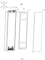
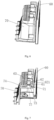
FIG. 1 is an exploded view of a refrigerator door with a replaceable door panel according to an embodiment of the present invention as viewed from a first angle of view. -
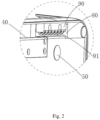
FIG. 2 is an enlarged view of a dashed region inFIG. 1 . -
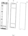
FIG. 3 is an exploded view of the refrigerator door with a replaceable door panel inFIG. 1 as viewed from a second angle of view. -
FIG. 4 is an enlarged view of a dashed region inFIG. 3 . -
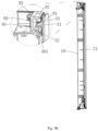
FIG. 5A through FIG. 5C are cross-sectional views of the refrigerator door with a replaceable door panel inFIG. 1 during the assembling. -
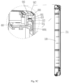
FIG. 6 is a view after the assembling of a front handle and a rear handle in a foam door body in the present invention. -
FIG. 7 is a cross-sectional view of after the front handle and the rear handle are assembled inFIG. 6 . -
FIG. 8 is an exploded view of a hook in another embodiment of the present invention. -
FIG. 9 is an exploded view of a side of the foam door body in a further embodiment of the present invention. - The present invention will be described in detail below in combination with embodiments shown in the figures. However, these embodiments do not limit the present invention, and structural or functional changes made by those having ordinary skill in the art according to these embodiments are all included in the protection scope of the present invention.
- As shown in
FIG. 1 through FIG. 5C , the present invention provides arefrigerator door 100 with a replaceable door panel, comprising: afoam door body 10, and afront panel 20 detachably connected to thefoam door body 10, wherein a first limiting member and a second limiting member are disposed on a front side of thefoam door body 10; aframe 21 is disposed on a rear side of thefront panel 20, theframe 21 is attached to a rear side of thefront panel 20, ahook 30 is disposed on theframe 21, and thehook 30 has aninsertion plate portion 33; when thefront panel 20 is assembled on the front side of thefoam door body 10, the first limiting member, in cooperation with theinsertion plate portion 33, limits a displacement of the front panel in a first direction; the second limiting member, in cooperation of theframe 21, limits a displacement of thefront panel 20 in a second direction. - In the present embodiment, the first direction and the second direction are perpendicular to each other. Specifically, the first limiting member is a
stopper 90 which is disposed in a receivinggroove 80 on a front side of thefoam door body 10, wherein theinsertion plate portion 33 of thehook 30 is horizontally inserted into thereceiving groove 80, and is elastically resisted by thestopper 90 in an up-down direction; the second limiting member is amagnetic member 50 which is embedded in thefoam door body 10. Themagnetic member 50 and theframe 21 magnetically attract each other in a front-rear direction perpendicular to thefront panel 20. - The
insertion plate portion 33 of thehook 30 is limited by thestopper 90 in the up-down direction, so that the displacement of thefront panel 20 in the up-down direction is limited; themagnetic member 50 and theframe 21 magnetically attract each other in the front-rear direction perpendicular to thefront panel 20, so that the displacement of thefront panel 20 in the front-rear direction is limited. Therefore, after thefront panel 20 is assembled to the front side of thefoam door body 10, thefront panel 20 will not move in the up-down direction and the front-rear direction. - The "front-rear direction" refers to a direction perpendicular to the
front panel 20; the "up-down" direction refers to a direction consistent with a length direction of thefront panel 20. - In a preferred embodiment, the
magnetic member 50 is for example a magnet, and theframe 21 is for example a metal frame, which magnetically attracts with the magnet. - As shown in
FIG. 2 , thestopper 90 comprises anelastic portion 91 and abody portion 92. An upper side of thebody portion 92 engages a top wall of thestopping groove 80, theelastic portion 91 is disposed below thebody portion 92, theelastic portion 91 extends from an opening on a front side of thestopping groove 80 towards rearward thestopping groove 80, and theelastic portion 91 elastically pushes and resists against theinsertion plate portion 33 downward in the up-down direction (as shown inFIG. 5C ). - In other embodiments of the invention, a lower side of the stopper engages a bottom wall of the stopping groove, the elastic portion is disposed on an upper side of the body portion, the elastic portion extends from the opening on the front side of the stopping groove towards rearward the stopping groove, and the elastic portion elastically pushes and resists against the insertion plate portion upwards in the up-down direction.
- That is to say, the displacement of the front panel in the up-down direction may be achieved in a way that the elastic portion of the stopper pushes and resists against the insertion plate portion of the hook upwards or downwards in the up-down direction.
- The
stopper 90 may be formed in the stoppinggroove 80 by being integrally formed with thefoam door body 10, and may also be fixed in the stoppinggroove 80 by being fastened with a screw. - As shown in
FIG. 2 andFIG. 5A throughFIG. 5C , a front end of theelastic portion 91 of thestopper 90 is connected to a front end of thebody portion 92, and a rear end of theelastic portion 91 is suspended on a side of thebody portion 92 and spaced apart agap 93 from thebody portion 92. In the present embodiment, theelastic portion 91 extends obliquely downward along the front end of thebody portion 92 toward the rear end of thebody portion 92. But the extension manner of theelastic portion 91 is not limited to this here. In other embodiments of the present invention, when the elastic portion is disposed on the upper side of the body portion, the elastic portion may extend obliquely upward from the front end of the body portion toward the rear end of the body portion. - The
gap 93 may provide a deformation space for theelastic portion 91. For example, when therefrigerator door 100 with a replaceable door panel is impacted by an external force, theelastic portion 91 is deformed to overcome the impact of the external force on the door body, thereby achieving the buffering and shock-absorbing effect without affecting theelastic portion 91 in elastically pushing and resisting against theinsertion plate portion 33; alternatively, when thefront panel 20 is detached from thefoam door body 10, theinsertion plate portion 30 squeezes theelastic portion 91. After theelastic portion 91 is deformed, it makes partial space so that theinsertion plate portion 30 can be more easily disengaged from thestopping groove 80, thereby making the detachment of thefront panel 20 easier. - As shown in
FIG. 3 andFIG. 4 , thehook 30 and theframe 21 are an integrally-formed sheet metal member which protrudes from theframe 21 towards thefoam door body 10; thehook 30 comprises a connectingportion 31, abent portion 32 and theinsertion plate portion 33; opposite ends of the connectingportion 31 are respectively connected with thebent portion 32 and theframe 21; theinsertion plate portion 33 protrudes from a lateral side of the connectingportion 31. - In the present embodiment, a pair of
insertion plate portions 33 protrude from two opposite lateral sides of the connectingportion 31, and a side of theinsertion plate portion 33 is connected to theframe 21. The pair ofinsertion plate portions 33 are respectively inserted into a pair of stoppinggrooves 80 on the front side of thefoam door body 10. - Corresponding to the connecting
portion 31 and thebent portion 32 of thehook 30, ahook groove 40 is disposed on the front side of thefoam door body 10, and the stoppinggroove 80 is disposed on left and right groove walls of thehook 40, wherein the stoppinggrooves 80 and thehook groove 40 are communicated with each other. When thefront panel 20 is assembled on the front side of thefoam door body 10, thebent portion 32 and the connectingportion 31 of thehook 30 enter thehook groove 40. - A front side of the
hook groove 40 is an open structure which comprises a step portion, ashielding block 401 is disposed on the step portion, a notch is formed between the shieldingblock 401 and the open structure, and thebent portion 32 and connectingportion 31 of thehook 30 enter through the notch into thehook groove 40. - As shown in
FIG. 8 and FIG. 9 , in another embodiment of the present invention, the bent portion 33' of the hook 30' further comprises apositioning notch 34; corresponding to thepositioning notch 34, apositioning block 42 is disposed on the rear groove wall 41 of the hook groove 40'; when thefront panel 20 is assembled on the front side of thefoam door body 10, thepositioning notch 34 and thepositioning block 42 snap-fit each other to limit the hook 30' from a displacement of the hook groove 40' in a left-right direction and thereby limit the displacement of thefront panel 20 relative to thefoam door body 10 in the left-right direction, so that thefront panel 20 is engaged on the foam door body more stably. The "left-right direction" refers to a direction consistent with a width direction of thefront panel 20. - As shown in
FIG. 1 ,FIG. 6 and FIG. 7 , the refrigerator door further comprises a handle portion comprising afront handle 60 and arear handle 70, wherein thefront handle 60 and therear handle 70, after being assembled together, are mounted in the receiving groove in thefoam door body 10. - A snap-fitting
groove 61 on thefront handle 60 and aboss 71 of therear handle 70 snap-fit each other. Theboss 71 comprises acavity 72, and a top end of theboss 71 is provided with a throughhole 73; acap body 62 is disposed on a side of the snap-fittinggroove 61 away from theboss 71, and thecap body 62 has acavity 621; the throughhole 73 communicates thecavity 72 with thecavity 621. A bolt passes through thecavity 72 and the throughhole 73 in turn and enter thecavity 621, locking theboss 71 and thecap body 62 to each other, so that thefront handle 60 and therear handle 70 are locked in an up-down direction. The "up-down" direction is parallel to a height direction of therefrigerator door 100 with the replaceable door panel. The snap-fittinggroove 61 snap-fits with theboss 71 to limit a displacement of thefront handle 60 and therear handle 70 in a horizontal direction, and the bolt passes through thecavity 72 and the throughhole 73 of theboss 71 to lock with thecap body 62 of the snap-fittinggroove 61 to limit the displacement of thefront handle 60 and therear handle 70 in the up-down direction. - The
boss 71 is formed on afirst plate 74 of therear handle 70, and the snap-fittinggroove 61 is formed on asecond plate 63 of thefront handle 60. Thefirst plate 74 and thesecond plate 63 extend opposite to each other. After thefront handle 60 and therear handle 70 are assembled, thefirst plate 74 is superimposed under thesecond plate 63. - As shown in
FIG. 5A through FIG. 5C , the assembling process offront panel 20 andfoam door body 10 is roughly as follows: - First, the
hook 30 on theframe 21 at the rear side of thefront panel 20 is inserted into thehook groove 40, thebent portion 32 falls to the bottom of thehook groove 40, theinsertion plate portion 33 of thehook 30 is flush with the lower portion of the stoppinggroove 80; then, thefront panel 20 is pushed close to thefoam door body 10, theinsertion plate portion 33 is horizontally inserted into the stoppinggroove 80 and is elastically and downwardly pushed and resisted by theelastic portion 91 of thestopper 90; then, theframe 21 and themagnetic member 50 on thefoam door body 10 magnetically attract each other in the front-rear direction, and thefront panel 20 is closely attached to the front side of thefoam door body 10. - The
insertion plate portion 33 of thehook 30 and thestopper 90 may limit thefront panel 20 in the up-down direction, and themagnetic member 50 and theframe 21 may limit thefront panel 20 in the front-rear direction. Since the limitation of thefront panel 20 in a plurality of directions significantly improves the strength of therefrigerator door 100 with a replaceable door panel, the influence exerted by the transportation and the drop condition on the refrigerator door may be effectively avoided even in the transportation process of the refrigerator door. - In addition, the upper end and lower end of the
frame 21 are respectively provided with thehook 30 having theinsertion plate portion 33, and the upper end and lower end of thefoam door body 10 are respectively provided with the stoppinggroove 90 and thestopper 80. Themagnetic members 50 are disposed at four corners of thefoam door body 10. In addition, themagnetic element 50 may be additionally provided below the stoppinggroove 80 to improve the magnetic stability. - To conclude, the present invention provides a refrigerator door with a replaceable door, wherein the hook on the rear side of the front panel and the first limiting member on the foam door body engage each other to limit the front panel in the first direction, and the frame on the rear side of the front panel and the second limiting member of the foam door body engage each other to limit the front panel in the second direction, thereby achieving the limitation of the front panel in a plurality of different directions, and thereby significantly improving the strength of the refrigerator door with the replaceable door panel, and thereby adapting to the influence exerted by the transportation and the drop condition on the refrigerator door with the replaceable door panel. In addition, the first limiting member elastically pushes and resists against the insertion plate portion of the hook so that the mounting and detachment of the front panel is made more convenient.
- It should be understood that although the description is described according to the embodiments, not every embodiment only comprises one independent technical solution, that such a description manner is only for the sake of clarity, that those skilled in the art should take the description as an integral part, and that the technical solutions in the embodiments may be suitably combined to form other embodiments understandable by those skilled in the art.
- The detailed descriptions set forth above are merely specific illustrations of feasible embodiments of the present invention, and are not intended to limit the scope of protection of the present invention. All equivalent embodiments or modifications that do not depart from the art spirit of the present invention should fall within the scope of protection of the present invention.
Claims (10)
- A refrigerator door with a replaceable door panel, wherein the refrigerator door comprises:a foam door body, and a front panel detachably connected to the foam door body;a first limiting member and a second limiting member are disposed on a front side of the foam door body;a frame is sandwiched between the front panel and the foam door body, the frame is attached to a rear side of the front panel, a hook is disposed on the frame, and the hook has an insertion plate portion;wherein when the front panel is assembled on the front side of the foam door body, the first limiting member, in cooperation with the insertion plate portion, limits a displacement of the front panel in a first direction; the second limiting member, in cooperation of the frame, limits a displacement of the front panel in a second direction.
- The refrigerator door with a replaceable door panel according to claim 1, wherein the first limiting member is a stopper which is disposed in a receiving groove of the foam door body, the insertion plate portion is inserted in the receiving groove, and the stopper elastically pushes and resists against the insertion plate portion in an up-down direction; the second limiting member is a magnetic member, and the magnetic member and the frame magnetically attract each other in a front-rear direction perpendicular to the front panel.
- The refrigerator door with a replaceable door panel according to claim 2, wherein the magnetic member is a magnet, the frame is a metal frame, and the metal frame and the magnetic member magnetically attract each other in the front-rear direction perpendicular to the front panel.
- The refrigerator door with a replaceable door panel according to claim 2, wherein the stopper comprises a body portion and an elastic portion, the elastic portion is disposed below the body portion, the elastic portion extends from an opening of the stopping groove towards rearward the stopping groove, and the elastic portion elastically pushes and resists against the insertion plate portion in the first direction.
- The refrigerator door with a replaceable door panel according to claim 4, wherein a front end of the elastic portion is connected to a front end of the body portion, and a rear end of the elastic portion is suspended below the body portion and spaced apart a gap from the body portion.
- The refrigerator door with a replaceable door panel according to claim 5, wherein the elastic portion extends obliquely downward along the front end of the body portion toward the rear end of the body portion.
- The refrigerator door with a replaceable door panel according to claim 1, wherein a positioning block is disposed in the hook groove, the hook comprises a bent portion, a positioning notch is disposed on the bent portion, wherein when the front panel is assembled on the front side of the foam door body, the bent portion is inserted in the hook groove, and the positioning notch and the positioning block snap-fit each other.
- The refrigerator door with a replaceable door panel according to claim 7, wherein the hook further comprises a connecting portion, both ends of the connecting portion are respectively connected with the bent portion and the frame, and the insertion plate portion is located on a lateral side of the connecting portion and protrudes in a direction away from the lateral side.
- The refrigerator door with a replaceable door panel according to claim 1, wherein the refrigerator door further comprises a handle portion comprising a front handle and a rear handle, the front handle and the rear handle are respectively assembled in the receiving groove of the foam door body, and wherein a snap-fitting groove on the front handle and a boss of the rear handle snap-fit each other.
- The refrigerator door with a replaceable door panel according to claim 9, wherein the boss comprises a cavity, and a top end of the boss is provided with a through hole; a cap body is disposed on a side of the snap-fitting groove away from the boss, and the cap body has another cavity, the through hole communicates the cavity of the boss with the another cavity of the cap body, wherein a bolt passes through the cavity and the through hole of the boss in turn and enter the another cavity of the cap body, thereby locking the boss and the cap body to each other.
Applications Claiming Priority (2)
| Application Number | Priority Date | Filing Date | Title |
|---|---|---|---|
| CN202010623440.8A CN113865236B (en) | 2020-06-30 | 2020-06-30 | Refrigerator doors with replaceable fronts |
| PCT/CN2021/100878 WO2022001696A1 (en) | 2020-06-30 | 2021-06-18 | Refrigerator door having replaceable door surface |
Publications (3)
| Publication Number | Publication Date |
|---|---|
| EP4174416A1 true EP4174416A1 (en) | 2023-05-03 |
| EP4174416A4 EP4174416A4 (en) | 2023-11-22 |
| EP4174416B1 EP4174416B1 (en) | 2025-11-19 |
Family
ID=78980981
Family Applications (1)
| Application Number | Title | Priority Date | Filing Date |
|---|---|---|---|
| EP21832151.1A Active EP4174416B1 (en) | 2020-06-30 | 2021-06-18 | Refrigerator door with a replaceable door panel |
Country Status (4)
| Country | Link |
|---|---|
| US (1) | US12292227B2 (en) |
| EP (1) | EP4174416B1 (en) |
| CN (1) | CN113865236B (en) |
| WO (1) | WO2022001696A1 (en) |
Families Citing this family (4)
| Publication number | Priority date | Publication date | Assignee | Title |
|---|---|---|---|---|
| CN113865235B (en) * | 2020-06-30 | 2023-02-17 | 青岛海尔电冰箱有限公司 | Refrigerator doors with replaceable fronts |
| CN114076479A (en) * | 2020-08-10 | 2022-02-22 | 青岛海尔特种电冰箱有限公司 | Refrigerator door with replaceable door face |
| US12133033B2 (en) | 2022-10-12 | 2024-10-29 | Concierge Audio LLC | Customizable speaker system |
| US20250198693A1 (en) * | 2023-12-18 | 2025-06-19 | Whirlpool Corporation | Vacuum port pressure sensor cover |
Family Cites Families (41)
| Publication number | Priority date | Publication date | Assignee | Title |
|---|---|---|---|---|
| US4383519A (en) * | 1981-06-10 | 1983-05-17 | Mills Products, Inc. | Door frame and handle combination |
| DE4239961C2 (en) * | 1992-11-27 | 1998-07-02 | Bosch Siemens Hausgeraete | Furniture door, in particular door of a refrigerator |
| DE4334761A1 (en) * | 1993-10-12 | 1995-04-13 | Bosch Siemens Hausgeraete | Household appliance for installation in a furniture niche in a kitchenette or the like |
| CN2499768Y (en) * | 2000-09-30 | 2002-07-10 | 伊莱克斯中意(长沙)电冰箱有限公司 | Refrigerator door capable of changing face plate |
| US6840773B2 (en) * | 2002-03-07 | 2005-01-11 | Jan Anderson | Decorative magnetic sheet and method for decorating an appliance |
| FI6003U1 (en) | 2003-05-28 | 2003-11-18 | Helkama Forste Oy | Surface structure for household appliances and refrigeration |
| DE202004014374U1 (en) | 2004-09-16 | 2004-12-30 | O + F A-Line GmbH Hausgeräte Vertrieb | fridge |
| KR100577373B1 (en) * | 2004-10-25 | 2006-05-10 | 위니아만도 주식회사 | Decorative panel fastening structure of Kimchi storage |
| KR20060068754A (en) * | 2004-12-17 | 2006-06-21 | 주식회사 대우일렉트로닉스 | Door open pressure increase prevention structure of refrigerator |
| BRPI0613196B1 (en) * | 2005-07-20 | 2020-11-10 | Lg Electronics Inc. | refrigerator door |
| US7770985B2 (en) * | 2006-02-15 | 2010-08-10 | Maytag Corporation | Kitchen appliance having floating glass panel |
| JP2008057899A (en) | 2006-09-01 | 2008-03-13 | Hitachi Appliances Inc | refrigerator |
| KR100781602B1 (en) * | 2006-12-01 | 2007-12-05 | 주식회사 대우일렉트로닉스 | Decorative panel support structure of refrigerator |
| DE102008019416A1 (en) * | 2008-04-17 | 2009-10-22 | BSH Bosch und Siemens Hausgeräte GmbH | Fitting structure and method for the correct installation of a decorative plate on a door of a household appliance |
| IT1399435B1 (en) * | 2010-04-13 | 2013-04-19 | Gatto S P A | DOOR FOR FURNITURE WITH REMOVABLE PANEL - INTERCHANGEABLE. |
| CN103201230B (en) * | 2010-09-14 | 2016-07-13 | 康宁股份有限公司 | Electric pallet and its installation |
| CN102384627B (en) * | 2011-12-22 | 2014-01-15 | 合肥美的电冰箱有限公司 | Door body used for refrigerator and refrigerator with door body |
| JP5488747B2 (en) * | 2012-08-06 | 2014-05-14 | パナソニック株式会社 | refrigerator |
| DE102013211471A1 (en) * | 2013-06-19 | 2014-12-24 | BSH Bosch und Siemens Hausgeräte GmbH | Door for a household appliance with a cover shell and household appliance with such a door |
| CN104422237B (en) * | 2013-08-29 | 2018-11-23 | 博西华电器(江苏)有限公司 | Door and refrigerator for refrigerator |
| WO2015033754A1 (en) * | 2013-09-05 | 2015-03-12 | ハイアールアジアインターナショナル株式会社 | Refrigerator door |
| JP6187333B2 (en) * | 2014-03-11 | 2017-08-30 | 三菱電機株式会社 | Storage and refrigerator |
| CN105333680B (en) * | 2014-07-18 | 2019-02-26 | 博西华电器(江苏)有限公司 | refrigerator |
| CN204478663U (en) | 2014-12-25 | 2015-07-15 | 合肥美的电冰箱有限公司 | The door body of refrigeration plant and there is its refrigeration plant |
| JP6460832B2 (en) * | 2015-02-24 | 2019-01-30 | シャープ株式会社 | Cooling room door |
| CN105333668A (en) * | 2015-11-24 | 2016-02-17 | 青岛海尔股份有限公司 | Refrigerator |
| KR102828393B1 (en) * | 2016-12-15 | 2025-07-02 | 삼성전자주식회사 | Refrigerator |
| US10317128B2 (en) * | 2017-01-03 | 2019-06-11 | Samsung Electronics Co., Ltd. | Refrigerator |
| US10470641B2 (en) * | 2017-08-21 | 2019-11-12 | Whirlpool Corporation | Dishwasher having a decorative panel |
| CN107700988B (en) * | 2017-09-18 | 2019-05-31 | 青岛海尔股份有限公司 | Door locking device and refrigerator having the same |
| CN207299701U (en) | 2017-09-20 | 2018-05-01 | 宁波韩电电器有限公司 | A kind of refrigerator of exchangeable panel |
| CN107702418B (en) | 2017-09-30 | 2021-09-21 | 合肥华凌股份有限公司 | Door body assembly of refrigerator and refrigerator with door body assembly |
| CN208765356U (en) | 2018-09-06 | 2019-04-19 | 合肥美的电冰箱有限公司 | Refrigerator door and refrigerator |
| CN210220367U (en) * | 2018-12-26 | 2020-03-31 | 青岛海高设计制造有限公司 | Refrigerator door and refrigerator |
| KR102633905B1 (en) * | 2019-01-31 | 2024-02-05 | 엘지전자 주식회사 | Refrigerator Capable of Sound Input |
| WO2020213861A1 (en) * | 2019-04-15 | 2020-10-22 | Samsung Electronics Co., Ltd. | Refrigerator |
| KR102312667B1 (en) * | 2019-04-15 | 2021-10-15 | 삼성전자주식회사 | Refrigerator |
| CN210119057U (en) * | 2019-05-30 | 2020-02-28 | 青岛海信电子技术服务有限公司 | A kind of refrigerator |
| CN112944776B (en) * | 2019-08-20 | 2022-10-28 | 三星电子株式会社 | Refrigerator and household appliance |
| CN113865232B (en) * | 2020-06-30 | 2022-07-26 | 青岛海尔电冰箱有限公司 | Refrigerator door with replaceable door face |
| CN113865233A (en) * | 2020-06-30 | 2021-12-31 | 青岛海尔电冰箱有限公司 | Refrigerator door with replaceable door face |
-
2020
- 2020-06-30 CN CN202010623440.8A patent/CN113865236B/en active Active
-
2021
- 2021-06-18 WO PCT/CN2021/100878 patent/WO2022001696A1/en not_active Ceased
- 2021-06-18 US US18/013,208 patent/US12292227B2/en active Active
- 2021-06-18 EP EP21832151.1A patent/EP4174416B1/en active Active
Also Published As
| Publication number | Publication date |
|---|---|
| CN113865236B (en) | 2023-02-17 |
| US12292227B2 (en) | 2025-05-06 |
| EP4174416B1 (en) | 2025-11-19 |
| US20230251023A1 (en) | 2023-08-10 |
| WO2022001696A1 (en) | 2022-01-06 |
| EP4174416A4 (en) | 2023-11-22 |
| CN113865236A (en) | 2021-12-31 |
Similar Documents
| Publication | Publication Date | Title |
|---|---|---|
| US12292227B2 (en) | Refrigerator door with replaceable door panel | |
| EP4174418B1 (en) | Refrigerator door with a replaceable door panel | |
| US20230251024A1 (en) | Refrigerator door with replaceable door panel | |
| CN102084139B (en) | Two-part assembly structure | |
| US11988438B2 (en) | Refrigerator door with replaceable door panel | |
| EP4174420B1 (en) | Refrigerator door with a replaceable door panel | |
| EP4174421B1 (en) | Refrigerator door with a replaceable door panel | |
| US10772422B1 (en) | Connecting device | |
| CN214307818U (en) | A refrigerator door assembly and refrigerator | |
| US20190088572A1 (en) | Heast sink fastening seat for use with electrical connector | |
| EP4427633A1 (en) | Furniture system and furniture assembly thereof | |
| JP3202075U (en) | Trolley | |
| CN202524675U (en) | Screen and screen combination with quick release structure | |
| CN112050546B (en) | Display components and refrigerators | |
| KR20180068628A (en) | Display Part Assembly Structure of refrigerator | |
| KR200315701Y1 (en) | Structure for coupling sectional table | |
| KR102090128B1 (en) | Box mounting apparatus for vehicles | |
| US12324516B2 (en) | Furniture system and furniture assembly thereof | |
| KR19990011183U (en) | Top plate coupling structure of washing machine | |
| CN212055383U (en) | Furniture L-shaped connecting piece and storage cabinet | |
| KR200446839Y1 (en) | Combination structure of elevator switch | |
| CN209971889U (en) | Thermal printer with paper bin reinforcing ribs | |
| JP2019190060A (en) | magnet catch | |
| KR101568931B1 (en) | Structure of the combined glasses frame | |
| CN213993348U (en) | Handle assembly and container lid |
Legal Events
| Date | Code | Title | Description |
|---|---|---|---|
| STAA | Information on the status of an ep patent application or granted ep patent |
Free format text: STATUS: THE INTERNATIONAL PUBLICATION HAS BEEN MADE |
|
| PUAI | Public reference made under article 153(3) epc to a published international application that has entered the european phase |
Free format text: ORIGINAL CODE: 0009012 |
|
| STAA | Information on the status of an ep patent application or granted ep patent |
Free format text: STATUS: REQUEST FOR EXAMINATION WAS MADE |
|
| 17P | Request for examination filed |
Effective date: 20221223 |
|
| AK | Designated contracting states |
Kind code of ref document: A1 Designated state(s): AL AT BE BG CH CY CZ DE DK EE ES FI FR GB GR HR HU IE IS IT LI LT LU LV MC MK MT NL NO PL PT RO RS SE SI SK SM TR |
|
| DAV | Request for validation of the european patent (deleted) | ||
| DAX | Request for extension of the european patent (deleted) | ||
| A4 | Supplementary search report drawn up and despatched |
Effective date: 20231024 |
|
| RIC1 | Information provided on ipc code assigned before grant |
Ipc: F25D 23/02 20060101AFI20231018BHEP |
|
| GRAP | Despatch of communication of intention to grant a patent |
Free format text: ORIGINAL CODE: EPIDOSNIGR1 |
|
| STAA | Information on the status of an ep patent application or granted ep patent |
Free format text: STATUS: GRANT OF PATENT IS INTENDED |
|
| INTG | Intention to grant announced |
Effective date: 20250618 |
|
| GRAS | Grant fee paid |
Free format text: ORIGINAL CODE: EPIDOSNIGR3 |
|
| GRAA | (expected) grant |
Free format text: ORIGINAL CODE: 0009210 |
|
| STAA | Information on the status of an ep patent application or granted ep patent |
Free format text: STATUS: THE PATENT HAS BEEN GRANTED |
|
| AK | Designated contracting states |
Kind code of ref document: B1 Designated state(s): AL AT BE BG CH CY CZ DE DK EE ES FI FR GB GR HR HU IE IS IT LI LT LU LV MC MK MT NL NO PL PT RO RS SE SI SK SM TR |
|
| RAP3 | Party data changed (applicant data changed or rights of an application transferred) |
Owner name: CHONGQING HAIER REFRIGERATION ELECTRIC APPLIANCECO., LTD. Owner name: QINGDAO HAIER REFRIGERATOR CO., LTD Owner name: HAIER SMART HOME CO., LTD. |
|
| REG | Reference to a national code |
Ref country code: CH Ref legal event code: F10 Free format text: ST27 STATUS EVENT CODE: U-0-0-F10-F00 (AS PROVIDED BY THE NATIONAL OFFICE) Effective date: 20251119 Ref country code: GB Ref legal event code: FG4D |
|
| REG | Reference to a national code |
Ref country code: DE Ref legal event code: R096 Ref document number: 602021042764 Country of ref document: DE |
|
| REG | Reference to a national code |
Ref country code: IE Ref legal event code: FG4D |
|
| REG | Reference to a national code |
Ref country code: NL Ref legal event code: MP Effective date: 20251119 |
|
| PG25 | Lapsed in a contracting state [announced via postgrant information from national office to epo] |
Ref country code: ES Free format text: LAPSE BECAUSE OF FAILURE TO SUBMIT A TRANSLATION OF THE DESCRIPTION OR TO PAY THE FEE WITHIN THE PRESCRIBED TIME-LIMIT Effective date: 20251119 |
|
| REG | Reference to a national code |
Ref country code: LT Ref legal event code: MG9D |
|
| PG25 | Lapsed in a contracting state [announced via postgrant information from national office to epo] |
Ref country code: NO Free format text: LAPSE BECAUSE OF FAILURE TO SUBMIT A TRANSLATION OF THE DESCRIPTION OR TO PAY THE FEE WITHIN THE PRESCRIBED TIME-LIMIT Effective date: 20260219 |
|
| PG25 | Lapsed in a contracting state [announced via postgrant information from national office to epo] |
Ref country code: HR Free format text: LAPSE BECAUSE OF FAILURE TO SUBMIT A TRANSLATION OF THE DESCRIPTION OR TO PAY THE FEE WITHIN THE PRESCRIBED TIME-LIMIT Effective date: 20251119 Ref country code: AT Free format text: LAPSE BECAUSE OF FAILURE TO SUBMIT A TRANSLATION OF THE DESCRIPTION OR TO PAY THE FEE WITHIN THE PRESCRIBED TIME-LIMIT Effective date: 20251119 Ref country code: FI Free format text: LAPSE BECAUSE OF FAILURE TO SUBMIT A TRANSLATION OF THE DESCRIPTION OR TO PAY THE FEE WITHIN THE PRESCRIBED TIME-LIMIT Effective date: 20251119 |
|
| REG | Reference to a national code |
Ref country code: AT Ref legal event code: MK05 Ref document number: 1859141 Country of ref document: AT Kind code of ref document: T Effective date: 20251119 |
|
| PG25 | Lapsed in a contracting state [announced via postgrant information from national office to epo] |
Ref country code: NL Free format text: LAPSE BECAUSE OF FAILURE TO SUBMIT A TRANSLATION OF THE DESCRIPTION OR TO PAY THE FEE WITHIN THE PRESCRIBED TIME-LIMIT Effective date: 20251119 |
|
| PG25 | Lapsed in a contracting state [announced via postgrant information from national office to epo] |
Ref country code: RS Free format text: LAPSE BECAUSE OF FAILURE TO SUBMIT A TRANSLATION OF THE DESCRIPTION OR TO PAY THE FEE WITHIN THE PRESCRIBED TIME-LIMIT Effective date: 20260219 |
|
| PG25 | Lapsed in a contracting state [announced via postgrant information from national office to epo] |
Ref country code: IS Free format text: LAPSE BECAUSE OF FAILURE TO SUBMIT A TRANSLATION OF THE DESCRIPTION OR TO PAY THE FEE WITHIN THE PRESCRIBED TIME-LIMIT Effective date: 20260319 |
|
| PG25 | Lapsed in a contracting state [announced via postgrant information from national office to epo] |
Ref country code: PT Free format text: LAPSE BECAUSE OF FAILURE TO SUBMIT A TRANSLATION OF THE DESCRIPTION OR TO PAY THE FEE WITHIN THE PRESCRIBED TIME-LIMIT Effective date: 20260319 |
|
| PG25 | Lapsed in a contracting state [announced via postgrant information from national office to epo] |
Ref country code: PL Free format text: LAPSE BECAUSE OF FAILURE TO SUBMIT A TRANSLATION OF THE DESCRIPTION OR TO PAY THE FEE WITHIN THE PRESCRIBED TIME-LIMIT Effective date: 20251119 |
|
| PG25 | Lapsed in a contracting state [announced via postgrant information from national office to epo] |
Ref country code: LV Free format text: LAPSE BECAUSE OF FAILURE TO SUBMIT A TRANSLATION OF THE DESCRIPTION OR TO PAY THE FEE WITHIN THE PRESCRIBED TIME-LIMIT Effective date: 20251119 |
|
| PG25 | Lapsed in a contracting state [announced via postgrant information from national office to epo] |
Ref country code: BG Free format text: LAPSE BECAUSE OF FAILURE TO SUBMIT A TRANSLATION OF THE DESCRIPTION OR TO PAY THE FEE WITHIN THE PRESCRIBED TIME-LIMIT Effective date: 20251119 |
|
| PG25 | Lapsed in a contracting state [announced via postgrant information from national office to epo] |
Ref country code: LT Free format text: LAPSE BECAUSE OF FAILURE TO SUBMIT A TRANSLATION OF THE DESCRIPTION OR TO PAY THE FEE WITHIN THE PRESCRIBED TIME-LIMIT Effective date: 20251119 |
|
| PG25 | Lapsed in a contracting state [announced via postgrant information from national office to epo] |
Ref country code: SM Free format text: LAPSE BECAUSE OF FAILURE TO SUBMIT A TRANSLATION OF THE DESCRIPTION OR TO PAY THE FEE WITHIN THE PRESCRIBED TIME-LIMIT Effective date: 20251119 |
|
| PG25 | Lapsed in a contracting state [announced via postgrant information from national office to epo] |
Ref country code: DK Free format text: LAPSE BECAUSE OF FAILURE TO SUBMIT A TRANSLATION OF THE DESCRIPTION OR TO PAY THE FEE WITHIN THE PRESCRIBED TIME-LIMIT Effective date: 20251119 |
|
| PG25 | Lapsed in a contracting state [announced via postgrant information from national office to epo] |
Ref country code: IT Free format text: LAPSE BECAUSE OF FAILURE TO SUBMIT A TRANSLATION OF THE DESCRIPTION OR TO PAY THE FEE WITHIN THE PRESCRIBED TIME-LIMIT Effective date: 20251119 |
|
| PGFP | Annual fee paid to national office [announced via postgrant information from national office to epo] |
Ref country code: DE Payment date: 20260612 Year of fee payment: 6 |
|
| PG25 | Lapsed in a contracting state [announced via postgrant information from national office to epo] |
Ref country code: EE Free format text: LAPSE BECAUSE OF FAILURE TO SUBMIT A TRANSLATION OF THE DESCRIPTION OR TO PAY THE FEE WITHIN THE PRESCRIBED TIME-LIMIT Effective date: 20251119 |
|
| PG25 | Lapsed in a contracting state [announced via postgrant information from national office to epo] |
Ref country code: CZ Free format text: LAPSE BECAUSE OF FAILURE TO SUBMIT A TRANSLATION OF THE DESCRIPTION OR TO PAY THE FEE WITHIN THE PRESCRIBED TIME-LIMIT Effective date: 20251119 |
|
| PG25 | Lapsed in a contracting state [announced via postgrant information from national office to epo] |
Ref country code: SK Free format text: LAPSE BECAUSE OF FAILURE TO SUBMIT A TRANSLATION OF THE DESCRIPTION OR TO PAY THE FEE WITHIN THE PRESCRIBED TIME-LIMIT Effective date: 20251119 |
|
| PG25 | Lapsed in a contracting state [announced via postgrant information from national office to epo] |
Ref country code: SE Free format text: LAPSE BECAUSE OF FAILURE TO SUBMIT A TRANSLATION OF THE DESCRIPTION OR TO PAY THE FEE WITHIN THE PRESCRIBED TIME-LIMIT Effective date: 20251119 |