EP4174361A1 - Double-shell tank and vessel - Google Patents
Double-shell tank and vessel Download PDFInfo
- Publication number
- EP4174361A1 EP4174361A1 EP20942157.7A EP20942157A EP4174361A1 EP 4174361 A1 EP4174361 A1 EP 4174361A1 EP 20942157 A EP20942157 A EP 20942157A EP 4174361 A1 EP4174361 A1 EP 4174361A1
- Authority
- EP
- European Patent Office
- Prior art keywords
- shell
- double
- tank
- inner shell
- outer shell
- Prior art date
- Legal status (The legal status is an assumption and is not a legal conclusion. Google has not performed a legal analysis and makes no representation as to the accuracy of the status listed.)
- Withdrawn
Links
Images


Classifications
-
- B—PERFORMING OPERATIONS; TRANSPORTING
- B63—SHIPS OR OTHER WATERBORNE VESSELS; RELATED EQUIPMENT
- B63B—SHIPS OR OTHER WATERBORNE VESSELS; EQUIPMENT FOR SHIPPING
- B63B25/00—Load-accommodating arrangements, e.g. stowing, trimming; Vessels characterised thereby
- B63B25/02—Load-accommodating arrangements, e.g. stowing, trimming; Vessels characterised thereby for bulk goods
- B63B25/08—Load-accommodating arrangements, e.g. stowing, trimming; Vessels characterised thereby for bulk goods fluid
- B63B25/12—Load-accommodating arrangements, e.g. stowing, trimming; Vessels characterised thereby for bulk goods fluid closed
- B63B25/16—Load-accommodating arrangements, e.g. stowing, trimming; Vessels characterised thereby for bulk goods fluid closed heat-insulated
-
- B—PERFORMING OPERATIONS; TRANSPORTING
- B63—SHIPS OR OTHER WATERBORNE VESSELS; RELATED EQUIPMENT
- B63B—SHIPS OR OTHER WATERBORNE VESSELS; EQUIPMENT FOR SHIPPING
- B63B25/00—Load-accommodating arrangements, e.g. stowing, trimming; Vessels characterised thereby
- B63B25/02—Load-accommodating arrangements, e.g. stowing, trimming; Vessels characterised thereby for bulk goods
- B63B25/08—Load-accommodating arrangements, e.g. stowing, trimming; Vessels characterised thereby for bulk goods fluid
- B63B25/082—Arrangements for minimizing pollution by accidents
-
- F—MECHANICAL ENGINEERING; LIGHTING; HEATING; WEAPONS; BLASTING
- F17—STORING OR DISTRIBUTING GASES OR LIQUIDS
- F17C—VESSELS FOR CONTAINING OR STORING COMPRESSED, LIQUEFIED OR SOLIDIFIED GASES; FIXED-CAPACITY GAS-HOLDERS; FILLING VESSELS WITH, OR DISCHARGING FROM VESSELS, COMPRESSED, LIQUEFIED, OR SOLIDIFIED GASES
- F17C3/00—Vessels not under pressure
- F17C3/02—Vessels not under pressure with provision for thermal insulation
- F17C3/025—Bulk storage in barges or on ships
-
- F—MECHANICAL ENGINEERING; LIGHTING; HEATING; WEAPONS; BLASTING
- F17—STORING OR DISTRIBUTING GASES OR LIQUIDS
- F17C—VESSELS FOR CONTAINING OR STORING COMPRESSED, LIQUEFIED OR SOLIDIFIED GASES; FIXED-CAPACITY GAS-HOLDERS; FILLING VESSELS WITH, OR DISCHARGING FROM VESSELS, COMPRESSED, LIQUEFIED, OR SOLIDIFIED GASES
- F17C3/00—Vessels not under pressure
- F17C3/02—Vessels not under pressure with provision for thermal insulation
- F17C3/04—Vessels not under pressure with provision for thermal insulation by insulating layers
-
- F—MECHANICAL ENGINEERING; LIGHTING; HEATING; WEAPONS; BLASTING
- F17—STORING OR DISTRIBUTING GASES OR LIQUIDS
- F17C—VESSELS FOR CONTAINING OR STORING COMPRESSED, LIQUEFIED OR SOLIDIFIED GASES; FIXED-CAPACITY GAS-HOLDERS; FILLING VESSELS WITH, OR DISCHARGING FROM VESSELS, COMPRESSED, LIQUEFIED, OR SOLIDIFIED GASES
- F17C3/00—Vessels not under pressure
- F17C3/02—Vessels not under pressure with provision for thermal insulation
- F17C3/08—Vessels not under pressure with provision for thermal insulation by vacuum spaces, e.g. Dewar flask
-
- B—PERFORMING OPERATIONS; TRANSPORTING
- B63—SHIPS OR OTHER WATERBORNE VESSELS; RELATED EQUIPMENT
- B63B—SHIPS OR OTHER WATERBORNE VESSELS; EQUIPMENT FOR SHIPPING
- B63B25/00—Load-accommodating arrangements, e.g. stowing, trimming; Vessels characterised thereby
- B63B25/02—Load-accommodating arrangements, e.g. stowing, trimming; Vessels characterised thereby for bulk goods
- B63B25/08—Load-accommodating arrangements, e.g. stowing, trimming; Vessels characterised thereby for bulk goods fluid
- B63B2025/087—Load-accommodating arrangements, e.g. stowing, trimming; Vessels characterised thereby for bulk goods fluid comprising self-contained tanks installed in the ship structure as separate units
-
- F—MECHANICAL ENGINEERING; LIGHTING; HEATING; WEAPONS; BLASTING
- F17—STORING OR DISTRIBUTING GASES OR LIQUIDS
- F17C—VESSELS FOR CONTAINING OR STORING COMPRESSED, LIQUEFIED OR SOLIDIFIED GASES; FIXED-CAPACITY GAS-HOLDERS; FILLING VESSELS WITH, OR DISCHARGING FROM VESSELS, COMPRESSED, LIQUEFIED, OR SOLIDIFIED GASES
- F17C2201/00—Vessel construction, in particular geometry, arrangement or size
- F17C2201/01—Shape
- F17C2201/0104—Shape cylindrical
-
- F—MECHANICAL ENGINEERING; LIGHTING; HEATING; WEAPONS; BLASTING
- F17—STORING OR DISTRIBUTING GASES OR LIQUIDS
- F17C—VESSELS FOR CONTAINING OR STORING COMPRESSED, LIQUEFIED OR SOLIDIFIED GASES; FIXED-CAPACITY GAS-HOLDERS; FILLING VESSELS WITH, OR DISCHARGING FROM VESSELS, COMPRESSED, LIQUEFIED, OR SOLIDIFIED GASES
- F17C2201/00—Vessel construction, in particular geometry, arrangement or size
- F17C2201/01—Shape
- F17C2201/0147—Shape complex
-
- F—MECHANICAL ENGINEERING; LIGHTING; HEATING; WEAPONS; BLASTING
- F17—STORING OR DISTRIBUTING GASES OR LIQUIDS
- F17C—VESSELS FOR CONTAINING OR STORING COMPRESSED, LIQUEFIED OR SOLIDIFIED GASES; FIXED-CAPACITY GAS-HOLDERS; FILLING VESSELS WITH, OR DISCHARGING FROM VESSELS, COMPRESSED, LIQUEFIED, OR SOLIDIFIED GASES
- F17C2201/00—Vessel construction, in particular geometry, arrangement or size
- F17C2201/03—Orientation
- F17C2201/035—Orientation with substantially horizontal main axis
-
- F—MECHANICAL ENGINEERING; LIGHTING; HEATING; WEAPONS; BLASTING
- F17—STORING OR DISTRIBUTING GASES OR LIQUIDS
- F17C—VESSELS FOR CONTAINING OR STORING COMPRESSED, LIQUEFIED OR SOLIDIFIED GASES; FIXED-CAPACITY GAS-HOLDERS; FILLING VESSELS WITH, OR DISCHARGING FROM VESSELS, COMPRESSED, LIQUEFIED, OR SOLIDIFIED GASES
- F17C2201/00—Vessel construction, in particular geometry, arrangement or size
- F17C2201/05—Size
- F17C2201/052—Size large (>1000 m3)
-
- F—MECHANICAL ENGINEERING; LIGHTING; HEATING; WEAPONS; BLASTING
- F17—STORING OR DISTRIBUTING GASES OR LIQUIDS
- F17C—VESSELS FOR CONTAINING OR STORING COMPRESSED, LIQUEFIED OR SOLIDIFIED GASES; FIXED-CAPACITY GAS-HOLDERS; FILLING VESSELS WITH, OR DISCHARGING FROM VESSELS, COMPRESSED, LIQUEFIED, OR SOLIDIFIED GASES
- F17C2203/00—Vessel construction, in particular walls or details thereof
- F17C2203/03—Thermal insulations
- F17C2203/0304—Thermal insulations by solid means
- F17C2203/0337—Granular
-
- F—MECHANICAL ENGINEERING; LIGHTING; HEATING; WEAPONS; BLASTING
- F17—STORING OR DISTRIBUTING GASES OR LIQUIDS
- F17C—VESSELS FOR CONTAINING OR STORING COMPRESSED, LIQUEFIED OR SOLIDIFIED GASES; FIXED-CAPACITY GAS-HOLDERS; FILLING VESSELS WITH, OR DISCHARGING FROM VESSELS, COMPRESSED, LIQUEFIED, OR SOLIDIFIED GASES
- F17C2203/00—Vessel construction, in particular walls or details thereof
- F17C2203/03—Thermal insulations
- F17C2203/0391—Thermal insulations by vacuum
-
- F—MECHANICAL ENGINEERING; LIGHTING; HEATING; WEAPONS; BLASTING
- F17—STORING OR DISTRIBUTING GASES OR LIQUIDS
- F17C—VESSELS FOR CONTAINING OR STORING COMPRESSED, LIQUEFIED OR SOLIDIFIED GASES; FIXED-CAPACITY GAS-HOLDERS; FILLING VESSELS WITH, OR DISCHARGING FROM VESSELS, COMPRESSED, LIQUEFIED, OR SOLIDIFIED GASES
- F17C2203/00—Vessel construction, in particular walls or details thereof
- F17C2203/06—Materials for walls or layers thereof; Properties or structures of walls or their materials
- F17C2203/0602—Wall structures; Special features thereof
- F17C2203/0612—Wall structures
- F17C2203/0626—Multiple walls
- F17C2203/0629—Two walls
-
- F—MECHANICAL ENGINEERING; LIGHTING; HEATING; WEAPONS; BLASTING
- F17—STORING OR DISTRIBUTING GASES OR LIQUIDS
- F17C—VESSELS FOR CONTAINING OR STORING COMPRESSED, LIQUEFIED OR SOLIDIFIED GASES; FIXED-CAPACITY GAS-HOLDERS; FILLING VESSELS WITH, OR DISCHARGING FROM VESSELS, COMPRESSED, LIQUEFIED, OR SOLIDIFIED GASES
- F17C2221/00—Handled fluid, in particular type of fluid
- F17C2221/01—Pure fluids
- F17C2221/012—Hydrogen
-
- F—MECHANICAL ENGINEERING; LIGHTING; HEATING; WEAPONS; BLASTING
- F17—STORING OR DISTRIBUTING GASES OR LIQUIDS
- F17C—VESSELS FOR CONTAINING OR STORING COMPRESSED, LIQUEFIED OR SOLIDIFIED GASES; FIXED-CAPACITY GAS-HOLDERS; FILLING VESSELS WITH, OR DISCHARGING FROM VESSELS, COMPRESSED, LIQUEFIED, OR SOLIDIFIED GASES
- F17C2221/00—Handled fluid, in particular type of fluid
- F17C2221/01—Pure fluids
- F17C2221/014—Nitrogen
-
- F—MECHANICAL ENGINEERING; LIGHTING; HEATING; WEAPONS; BLASTING
- F17—STORING OR DISTRIBUTING GASES OR LIQUIDS
- F17C—VESSELS FOR CONTAINING OR STORING COMPRESSED, LIQUEFIED OR SOLIDIFIED GASES; FIXED-CAPACITY GAS-HOLDERS; FILLING VESSELS WITH, OR DISCHARGING FROM VESSELS, COMPRESSED, LIQUEFIED, OR SOLIDIFIED GASES
- F17C2221/00—Handled fluid, in particular type of fluid
- F17C2221/03—Mixtures
- F17C2221/032—Hydrocarbons
- F17C2221/033—Methane, e.g. natural gas, CNG, LNG, GNL, GNC, PLNG
-
- F—MECHANICAL ENGINEERING; LIGHTING; HEATING; WEAPONS; BLASTING
- F17—STORING OR DISTRIBUTING GASES OR LIQUIDS
- F17C—VESSELS FOR CONTAINING OR STORING COMPRESSED, LIQUEFIED OR SOLIDIFIED GASES; FIXED-CAPACITY GAS-HOLDERS; FILLING VESSELS WITH, OR DISCHARGING FROM VESSELS, COMPRESSED, LIQUEFIED, OR SOLIDIFIED GASES
- F17C2223/00—Handled fluid before transfer, i.e. state of fluid when stored in the vessel or before transfer from the vessel
- F17C2223/01—Handled fluid before transfer, i.e. state of fluid when stored in the vessel or before transfer from the vessel characterised by the phase
- F17C2223/0146—Two-phase
- F17C2223/0153—Liquefied gas, e.g. LPG, GPL
- F17C2223/0161—Liquefied gas, e.g. LPG, GPL cryogenic, e.g. LNG, GNL, PLNG
-
- F—MECHANICAL ENGINEERING; LIGHTING; HEATING; WEAPONS; BLASTING
- F17—STORING OR DISTRIBUTING GASES OR LIQUIDS
- F17C—VESSELS FOR CONTAINING OR STORING COMPRESSED, LIQUEFIED OR SOLIDIFIED GASES; FIXED-CAPACITY GAS-HOLDERS; FILLING VESSELS WITH, OR DISCHARGING FROM VESSELS, COMPRESSED, LIQUEFIED, OR SOLIDIFIED GASES
- F17C2223/00—Handled fluid before transfer, i.e. state of fluid when stored in the vessel or before transfer from the vessel
- F17C2223/03—Handled fluid before transfer, i.e. state of fluid when stored in the vessel or before transfer from the vessel characterised by the pressure level
- F17C2223/033—Small pressure, e.g. for liquefied gas
-
- F—MECHANICAL ENGINEERING; LIGHTING; HEATING; WEAPONS; BLASTING
- F17—STORING OR DISTRIBUTING GASES OR LIQUIDS
- F17C—VESSELS FOR CONTAINING OR STORING COMPRESSED, LIQUEFIED OR SOLIDIFIED GASES; FIXED-CAPACITY GAS-HOLDERS; FILLING VESSELS WITH, OR DISCHARGING FROM VESSELS, COMPRESSED, LIQUEFIED, OR SOLIDIFIED GASES
- F17C2260/00—Purposes of gas storage and gas handling
- F17C2260/03—Dealing with losses
- F17C2260/031—Dealing with losses due to heat transfer
- F17C2260/033—Dealing with losses due to heat transfer by enhancing insulation
-
- F—MECHANICAL ENGINEERING; LIGHTING; HEATING; WEAPONS; BLASTING
- F17—STORING OR DISTRIBUTING GASES OR LIQUIDS
- F17C—VESSELS FOR CONTAINING OR STORING COMPRESSED, LIQUEFIED OR SOLIDIFIED GASES; FIXED-CAPACITY GAS-HOLDERS; FILLING VESSELS WITH, OR DISCHARGING FROM VESSELS, COMPRESSED, LIQUEFIED, OR SOLIDIFIED GASES
- F17C2270/00—Applications
- F17C2270/01—Applications for fluid transport or storage
- F17C2270/0102—Applications for fluid transport or storage on or in the water
- F17C2270/0105—Ships
-
- Y—GENERAL TAGGING OF NEW TECHNOLOGICAL DEVELOPMENTS; GENERAL TAGGING OF CROSS-SECTIONAL TECHNOLOGIES SPANNING OVER SEVERAL SECTIONS OF THE IPC; TECHNICAL SUBJECTS COVERED BY FORMER USPC CROSS-REFERENCE ART COLLECTIONS [XRACs] AND DIGESTS
- Y02—TECHNOLOGIES OR APPLICATIONS FOR MITIGATION OR ADAPTATION AGAINST CLIMATE CHANGE
- Y02E—REDUCTION OF GREENHOUSE GAS [GHG] EMISSIONS, RELATED TO ENERGY GENERATION, TRANSMISSION OR DISTRIBUTION
- Y02E60/00—Enabling technologies; Technologies with a potential or indirect contribution to GHG emissions mitigation
- Y02E60/30—Hydrogen technology
- Y02E60/32—Hydrogen storage
Definitions
- the present disclosure relates to a double-shell tank including an outer shell and an inner shell, and a ship including the double-shell tank.
- Double-shell tanks have been known as tanks that store low temperature liquids.
- the double-shell tank includes: an inner shell that stores a low temperature liquid; an outer shell that covers the inner shell from an outside and is located away from the inner shell by a predetermined distance; and a heat insulating layer between the inner shell and the outer shell.
- the heat insulating layer is made of powdered thermal insulation filled in between the inner shell and the outer shell. Pearlite is used as the powdered thermal insulation.
- the inner shell and the outer shell are completed, and then, the powdered thermal insulation is filled in between the inner shell in an empty state and the outer shell. Therefore, when the low temperature liquid is supplied to the inner shell, and this causes thermal contraction of the inner shell, the gap between the inner shell and the outer shell may increase, and the powdered thermal insulation filled in between the inner shell and the outer shell may move downward. When the powdered thermal insulation moves downward, a space in which the powdered thermal insulation does not exist is generated at a tank top portion of the double-shell tank, and the thickness of the heat insulating layer at the tank top portion decreases.
- the "tank top portion” denotes a portion corresponding to a top portion of the double-shell tank in a space that is located outside the inner shell and inside the outer shell.
- the heat insulating property of this portion deteriorates.
- cold heat of the inner shell may be transferred to the outer shell, and this may generate frost on the outer shell.
- frost on the outer shell.
- the corrosion of the outer shell may be caused.
- the amount of heat input to the inner shell increases by the deterioration of the heat insulating property, the amount of boil off gas of the low temperature liquid may increase, and the pressure of the inner shell may become excessive.
- the double-shell tank of PTL 1 includes the heat insulating layer including two layers, i.e., inner and outer layers that are an inside heat insulating layer made of a stretchable material (glass wool) that is stretchable in a radial direction of the inner shell and an outside heat insulating layer made of filler (pearlite).
- a space generated in the heat insulating layer by the thermal contraction of the inner shell is filled with the expanded stretchable material, and this suppresses the downward movement of the filler.
- an object of the present invention is to provide a double-shell tank that can maintain a heat insulating layer having an appropriate thickness at a tank top portion even after powdered thermal insulation moves downward by contraction deformation of an inner shell, which is an approach different from an approach of the double-shell tank of PTL 1, and a ship including the double-shell tank.
- a double-shell tank includes: an inner shell having a non-spherical hollow shell shape and including therein a storing portion; an outer shell that covers the inner shell; and powdered thermal insulation that is filled in a space surrounded by an outer wall of the inner shell and an inner wall of the outer shell to become a heat insulating layer.
- a size of a top portion gap between the inner shell in an empty state and the outer shell is larger than a size of a bottom portion gap between the inner shell and the outer shell.
- a thickness of the powdered thermal insulation of the top portion gap in the empty state is larger than the size of the bottom portion gap.
- the size of the top portion gap in the empty state be equal to or more than a value obtained by adding a height to the size of the bottom portion gap, the height being a height that is from a top portion of the outer shell and corresponds to a volume of a void generated when the powdered thermal insulation moves downward by contraction deformation of the inner shell.
- a ship according to one aspect of the present disclosure includes the double-shell tank configured as above.
- the size of the top portion gap of the double-shell tank is larger than the size of the bottom portion gap of the double-shell tank. Therefore, the heat insulating layer thicker than the heat insulating layer located at the tank bottom portion can be formed at the tank top portion in the empty state. Then, the thickness of the powdered thermal insulation of the top portion gap of the double-shell tank in the empty state is larger than the size of the bottom portion gap. Therefore, when the low temperature liquid is supplied to the inner shell, and this contracts the inner shell, the gap between the inner shell and the outer shell increases, and the powdered thermal insulation filled in between the inner shell and the outer shell moves downward. However, even when the powdered thermal insulation moves downward, the heat insulating layer having an adequate thickness is maintained at the tank top portion.
- the present disclosure can provide the double-shell tank that can maintain the heat insulating layer having an appropriate thickness at the tank top portion even after the powdered thermal insulation moves downward by the contraction deformation of the inner shell, and a ship including the double-shell tank.
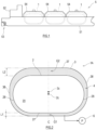
- FIG. 1 is a diagram showing a ship 5 including a double-shell tank 1 according to one embodiment of the present disclosure.
- the ship 5 shown in FIG. 1 is, for example, a liquefied gas carrier.
- the double-shell tank 1 is utilized to store a low temperature liquid, such as liquid hydrogen, liquid nitrogen, or liquefied natural gas.
- a bridge 52 is located at an upper-rear portion of a hull 51 of the ship 5, and a propulsor 53 is located at a lower-rear portion of the hull 51 of the ship 5.
- the hull 51 includes a plurality of (in the present embodiment, three) double-shell tanks 1 lined up in a ship longitudinal direction.
- the double-shell tanks 1 are located so as to project upward from an upper deck of the hull 51, and upper portions of the double-shell tanks 1 are covered with tank covers 54.
- Each double-shell tank 1A is supported by the hull 51 through a skirt or a post (not shown).
- Embodiments 1 to 5 of the double-shell tank 1 (double-shell tanks 1A to 1E) will be described.
- FIG. 2 is a sectional view showing the entire configuration of the double-shell tank 1A in an empty state according to Embodiment 1 of the present disclosure.
- FIG. 3 is a sectional view showing that the double-shell tank 1A shown in FIG. 2 is in a full state.
- the double-shell tank 1A shown in FIGS. 2 and 3 includes: an inner shell 2; an outer shell 3 that covers the inner shell 2; powdered thermal insulation 4 filled in between the inner shell 2 and the outer shell 3 to become a heat insulating layer; and a vacuum pump 6 that performs vacuum drawing with respect to a space between the inner shell 2 and the outer shell 3.
- the inner shell 2 has a non-spherical hollow shell shape and includes, for example, a large number of SUS panels welded to each other.
- a storing portion 20 that stores a low temperature liquid 7 in a sealed sate is inside the inner shell 2.
- the inner shell 2 allows contraction deformation and deformation recovery which are caused by a temperature difference between normal temperature at the time of tank construction and low temperature at the time when the low temperature liquid 7 is in the inner shell 2.
- the outer shell 3 has a non-spherical hollow shell shape larger than the inner shell 2 by one size and includes, for example, a large number of steel plates welded to each other.
- the inner shell 2 is supported by the outer shell 3 through, for example, a rod (not shown) that connects an outer wall of the inner shell 2 and an inner wall of the outer shell 3.
- the inner shell 2 has a hollow spherical shell shape extending in a horizontal direction.
- the inner shell 2 includes: a cylindrical body portion 27 extending in the horizontal direction; and hemispherical side portions 28 which close both ends of the body portion.
- a section of the inner shell 2 which is parallel to the ship longitudinal direction has an oval shape (also called a rounded rectangular shape) whose longitudinal direction corresponds to the horizontal direction.
- a section of the inner shell 2 which is parallel to a ship width direction has a circular shape.
- the section of the inner shell 2 which is parallel to the ship width direction may have an oval shape whose longitudinal direction corresponds to the horizontal direction
- the section of the inner shell 2 which is parallel to the ship longitudinal direction may have a circular shape.
- the outer shell 3 has a hollow spherical shell shape extending in the horizontal direction.
- the outer shell 3 includes: a substantially cylindrical body portion 37 whose center axis direction corresponds to the horizontal direction; and substantially hemispherical side portions 38 which close both ends of the body portion.
- a section of the outer shell 3 which is parallel to the ship longitudinal direction has a substantially oval shape whose longitudinal direction corresponds to the horizontal direction, and a section of the outer shell 3 which is parallel to the ship width direction has an oval shape whose longitudinal direction corresponds to an upper-lower direction.
- the section of the outer shell 3 which is parallel to the ship width direction may have a substantially oval shape whose longitudinal direction corresponds to the horizontal direction
- the section of the outer shell 3 which is parallel to the ship longitudinal direction may have an oval shape whose longitudinal direction corresponds to the upper-lower direction.
- the diameter of the body portion 37 of the outer shell 3 is larger than the diameter of the body portion 27 of the inner shell 2.
- a center 3c of the outer shell 3 is located higher than a center 2c of the inner shell 2.
- the powdered thermal insulation 4 is filled in a pressure sealed state in a space surrounded by an outer wall of the inner shell 2 and an inner wall of the outer shell 3.
- the powdered thermal insulation 4 is, for example, granular pearlite.
- the powdered thermal insulation 4 may be a known powdered thermal insulation other than pearlite.
- a fibrous heat insulating material such as glass wool, may be partially located in the space surrounded by the outer wall of the inner shell 2 and the inner wall of the outer shell 3.
- the space between the inner shell 2 and the outer shell 3 is subjected to forced air exhaustion by the vacuum pump 6, and therefore, is in a substantially vacuum state. Since the space filled with the powdered thermal insulation 4 is in a substantially vacuum state, the heat insulating effect is further improved. However, the space between the inner shell 2 and the outer shell 3 does not necessarily have to be in a vacuum state and may be filled with gas in accordance with the characteristics of the low temperature liquid 7 stored in the storing portion 20.
- a gap between the inner wall of the outer shell 3 and the outer wall of the inner shell 2 on the tank center line C at a tank bottom portion is referred to as a "bottom portion gap G1".
- a gap between the inner wall of the outer shell 3 and the outer wall of the inner shell 2 on the tank center line C at a tank top portion is referred to as a "top portion gap G2".
- the "tank top portion” denotes a portion corresponding to the top portion of the double-shell tank 1A in the space which is located outside the inner shell 2 and inside the outer shell 3.
- the "tank bottom portion” denotes a portion corresponding to the bottom portion of the double-shell tank 1A in the space which is outside the inner shell 2 and inside the outer shell 3.
- the inner shell 2 and the outer shell 3 are located such that the top portion gap G2 is larger than the bottom portion gap G1.
- the void volume ⁇ V can be obtained by calculation or simulation.
- the empty state denotes that the storing portion 20 of the inner shell 2 is in an empty state ( FIG.
- the full state denotes that the storing portion 20 of the inner shell 2 stores the low temperature liquid 7 to a predetermined full liquid level ( FIG. 3 ).
- a height which is from the tank top portion and corresponds to the void volume ⁇ V is represented by ⁇ L.
- the height ⁇ L can be obtained by calculation utilizing information, such as the shape of the outer shell 3.
- a size L2 of the top portion gap G2 in the empty state is equal to or more than a value obtained by adding the height ⁇ L to a size L1 of the bottom portion gap G1, the height ⁇ L being a height that is from the tank top portion and corresponds to the void volume ⁇ V.
- the size L2 of the top portion gap G2 in the empty state, the size L1 of the bottom portion gap G1, and the height ⁇ L satisfies Formula 1 below.
- the size L2 of the top portion gap G2 in the empty state be a small one of values that satisfy Formula 1.
- the thickness of the powdered thermal insulation 4 of the top portion gap G2 in the empty state is larger than the size L1 of the bottom portion gap G1.
- the thickness of the powdered thermal insulation 4 of the top portion gap G2 in the full state is equal to or more than the thickness of the powdered thermal insulation 4 of the bottom portion gap G1.
- the top portion gap G2 in the empty state may be filled with the powdered thermal insulation 4.
- the double-shell tank 1A includes: the inner shell 2 having a hollow shell shape and including therein the storing portion 20; the outer shell 3 that covers the inner shell 2; and the heat insulating material (in the present embodiment, the powdered thermal insulation 4) that is filled in the space surrounded by the outer wall of the inner shell 2 and the inner wall of the outer shell 3 to become the heat insulating layer. Then, the size of the top portion gap G2 between the inner shell 2 in the empty state and the outer shell 3 is larger than the size of the bottom portion gap G1 between the inner shell 2 and the outer shell 3.
- the thickness of the powdered thermal insulation 4 of the top portion gap G2 in the empty state be larger than the size L1 of the bottom portion gap G1.
- the size L2 of the top portion gap G2 in the empty state be equal to or more than a value obtained by adding the height ⁇ L to the size L1 of the bottom portion gap G1, the height ⁇ L being a height that is from the top portion of the outer shell 3 and corresponds to the volume (void volume ⁇ V) of the void generated when the powdered thermal insulation 4 moves downward by the contraction deformation of the inner shell 2.
- the heat insulating layer thicker than the heat insulating layer at the tank bottom portion is located at the tank top portion (see FIG. 2 ). Then, when the low temperature liquid 7 is supplied to the inner shell 2, and this contracts the inner shell 2, the gap between the inner shell 2 and the outer shell 3 increases, and the powdered thermal insulation 4 filled in between the inner shell 2 and the outer shell 3 moves downward. However, even after the powdered thermal insulation 4 moves downward, the heat insulating layer having an adequate thickness L2' is maintained at the tank top portion (see FIG. 3 ).
- the heat insulating layer having the appropriate thickness L2' can be maintained at the tank top portion.
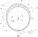
- FIG. 4 is a sectional view showing the entire configuration of the double-shell tank 1B in the empty state according to Embodiment 2 of the present disclosure.
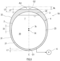
- FIG. 5 is a sectional view showing that the double-shell tank 1B shown in FIG. 4 is in the full state.
- the same reference signs are used for the same or similar components as or to those in Embodiment 1, and the repetition of the same explanation is avoided.
- the double-shell tank 1B includes: the inner shell 2 having a non-spherical shape and including therein the storing portion 20; the outer shell 3 that covers the inner shell 2; and the powdered thermal insulation 4 that is filled in the space surrounded by the outer wall of the inner shell 2 and the inner wall of the outer shell 3 to become the heat insulating layer.
- the inner shell 2 has a hollow spherical shell shape extending in the upper-lower direction.
- the inner shell 2 includes a lower hemispherical shell portion 21, an upper hemispherical shell portion 22, and a tubular body portion 23 connecting the lower hemispherical shell portion 21 and the upper hemispherical shell portion 22.
- the diameter of the lower hemispherical shell portion 21, the diameter of the upper hemispherical shell portion 22, and the diameter of the body portion 23 are equal to each other.
- the outer shell 3 has a hollow spherical shell shape extending in the upper-lower direction.
- the outer shell 3 includes a lower hemispherical shell portion 31, an upper hemispherical shell portion 32, and a tubular body portion 33 connecting the lower hemispherical shell portion 31 and the upper hemispherical shell portion 32 in the upper-lower direction.
- the diameter of the lower hemispherical shell portion 31, the diameter of the upper hemispherical shell portion 32, and the diameter of the body portion 33 are equal to each other, and this diameter is larger than the diameter of the inner shell 2.
- the height of the body portion 33 of the outer shell 3 is larger than the height of the body portion 23 of the inner shell 2.
- the inner shell 2 and the outer shell 3 are located such that a center 21c of the lower hemispherical shell portion 21 of the inner shell 2 and a center 31c of the lower hemispherical shell portion 31 of the outer shell 3 coincide with each other.
- the size L2 of the top portion gap G2 between the inner shell 2 and the outer shell 3 is larger than the size L1 of the bottom portion gap G1 between the inner shell 2 and the outer shell 3.
- the thickness of the powdered thermal insulation 4 of the top portion gap G2 in the empty state is larger than the size L1 of the bottom portion gap G1.
- the outer shell 3 includes the lower hemispherical shell portion 31, the upper hemispherical shell portion 32, and the tubular body portion 33 connecting the lower hemispherical shell portion 31 and the upper hemispherical shell portion 32
- the inner shell 2 includes the lower hemispherical shell portion 21, the upper hemispherical shell portion 22, and the tubular body portion 23 connecting the lower hemispherical shell portion 21 and the upper hemispherical shell portion 22, and the height of the body portion 33 of the outer shell 3 is larger than the height of the body portion 23 of the inner shell 2.
- the inner shell 2 has a spherical shell shape extending in the upper-lower direction. Therefore, in addition to the operational advantage of the double-shell tank 1A according to Embodiment 1, the double-shell tank 1B can obtain an operational advantage in which the capacity of the storing portion 20 relative to an occupied floor area can be made larger than when each of the inner shell 2 and the outer shell 3 has a perfectly spherical shell shape.
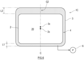
- FIG. 6 is a sectional view showing the entire configuration of the double-shell tank 1C in the empty state according to Embodiment 3 of the present disclosure.
- FIG. 7 is a sectional view showing that the double-shell tank 1C shown in FIG. 6 is in the full state.
- the same reference signs are used for the same or similar components as or to those in Embodiment 1, and the repetition of the same explanation is avoided.
- the double-shell tank 1C includes: the inner shell 2 having a non-spherical shape and including therein the storing portion 20; the outer shell 3 that covers the inner shell 2; and the powdered thermal insulation 4 that is filled in the space surrounded by the outer wall of the inner shell 2 and the inner wall of the outer shell 3 to become the heat insulating layer.
- each of the outer shell 3 and the inner shell 2 has a rectangular solid hollow shell shape.
- each of the outer shell 3 and the inner shell 2 is a rectangular tank. Then, the center 3c of the outer shell 3 is located higher than the center 2c of the inner shell 2.
- the size L2 of the top portion gap G2 between the inner shell 2 and the outer shell 3 is larger than the size L1 of the bottom portion gap G1 between the inner shell 2 and the outer shell 3.
- the thickness of the powdered thermal insulation 4 of the top portion gap G2 in the empty state is larger than the size L1 of the bottom portion gap G1.
- the double-shell tank 1C according to the present embodiment can obtain an operational advantage in which the capacity of the storing portion 20 relative to an occupied floor area can be made larger than when each of the inner shell 2 and the outer shell 3 has a perfectly spherical shell shape.
- FIG. 8 is a sectional view showing the entire configuration of the double-shell tank 1D in the empty state according to Embodiment 4 of the present disclosure.
- the same reference signs are used for the same or similar components as or to those in Embodiment 1, and the repetition of the same explanation is avoided.
- the double-shell tank 1D includes: the inner shell 2 having a non-spherical shape and including therein the storing portion 20; the outer shell 3 that covers the inner shell 2; and the powdered thermal insulation 4 that is filled in the space surrounded by the outer wall of the inner shell 2 and the inner wall of the outer shell 3 to become the heat insulating layer.
- each of the outer shell 3 and the inner shell 2 has a flat-bottom cylindrical hollow shell shape.
- the inner shell 2 includes: a circular flat bottom portion; a cylindrical body portion standing from a periphery of the bottom; and a top portion connected to an upper portion of the body portion and having a hemispherical shell shape.
- the outer shell 3 includes: a circular flat bottom portion; a cylindrical body portion standing from a periphery of the bottom; and a top portion connected to an upper portion of the body portion and having a hemispherical shell shape.
- the body portion of the outer shell 3 is larger in diameter and height than the body portion of the inner shell 2. Then, the center 3c of the outer shell 3 is located higher than the center 2c of the inner shell 2.
- the size L2 of the top portion gap G2 between the inner shell 2 and the outer shell 3 is larger than the size L1 of the bottom portion gap G1 between the inner shell 2 and the outer shell 3.
- the thickness of the powdered thermal insulation 4 of the top portion gap G2 in the empty state is larger than the size L1 of the bottom portion gap G1.
- the double-shell tank 1D according to the present embodiment can obtain an operational advantage in which the capacity of the storing portion 20 relative to an occupied floor area can be made larger than when each of the inner shell 2 and the outer shell 3 has a perfectly spherical shell shape.
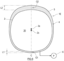
- FIG. 9 is a sectional view showing the entire configuration of the double-shell tank 1E in the empty state according to Embodiment 5 of the present disclosure.
- the same reference signs are used for the same or similar components as or to those in Embodiment 1, and the repetition of the same explanation is avoided.
- the double-shell tank 1E includes: the inner shell 2 having a non-spherical shape and including therein the storing portion 20; the outer shell 3 that covers the inner shell 2; and the powdered thermal insulation 4 that is filled in the space surrounded by the outer wall of the inner shell 2 and the inner wall of the outer shell 3 to become the heat insulating layer.
- the inner shell 2 includes: a top portion and a bottom portion, each of which has a shape of a part of a perfect sphere; and a body portion which has a shape of a part of a non-perfect sphere.
- the top portion and the body portion are smoothly continuous with each other, and the bottom portion and the body portion are smoothly continuous with each other.
- a curvature center of the top portion is located lower than the center 2c of the inner shell 2, and a curvature center of the bottom portion is located higher than the center 2c of the inner shell 2.
- the diameter of an equator portion of the body portion is substantially equal to the diameter of a virtual perfect sphere a part of which is formed by each of the top portion and the body portion.
- a connection portion between the body portion and the top portion and a connection portion between the body portion and the bottom portion expand outward beyond the virtual perfect sphere a part of which is formed by each of the top portion and the body portion.
- the outer shell 3 includes: a top portion and a bottom portion, each of which has a shape of a part of a perfect sphere; and a body portion which has a shape of a part of a non-perfect sphere.
- a curvature radius of the top portion of the outer shell 3 and a curvature radius of the bottom portion of the outer shell 3 are larger than a curvature radius of the top portion of the inner shell 2 and a curvature radius of the bottom portion of the inner shell 2.
- a height of the body portion of the outer shell 3 is larger than a height of the body portion of the inner shell 2. Then, the center 3c of the outer shell 3 is located higher than the center 2c of the inner shell 2.
- the size L2 of the top portion gap G2 between the inner shell 2 and the outer shell 3 is larger than the size L1 of the bottom portion gap G1 between the inner shell 2 and the outer shell 3.
- the thickness of the powdered thermal insulation 4 of the top portion gap G2 in the empty state is larger than the size L1 of the bottom portion gap G1.
- the double-shell tank 1E according to the present embodiment can obtain an operational advantage in which the capacity of the storing portion 20 relative to an occupied floor area can be made large.
- each of the double-shell tanks 1 and 1A to 1E according to the above embodiments is supported by the hull 51
- the double-shell tanks 1 and 1A to 1E may be located on the ground.
- the heat insulating layer having an adequate thickness is maintained at the tank top portion even when the powdered thermal insulation 4 moves downward by rolling, pitching, or vibrating of the hull 51.
Landscapes
- Engineering & Computer Science (AREA)
- Mechanical Engineering (AREA)
- Physics & Mathematics (AREA)
- Thermal Sciences (AREA)
- General Engineering & Computer Science (AREA)
- Chemical & Material Sciences (AREA)
- Combustion & Propulsion (AREA)
- Ocean & Marine Engineering (AREA)
- Health & Medical Sciences (AREA)
- Environmental & Geological Engineering (AREA)
- Public Health (AREA)
- Filling Or Discharging Of Gas Storage Vessels (AREA)
Abstract
Description
- The present disclosure relates to a double-shell tank including an outer shell and an inner shell, and a ship including the double-shell tank.
- Double-shell tanks have been known as tanks that store low temperature liquids. Generally, the double-shell tank includes: an inner shell that stores a low temperature liquid; an outer shell that covers the inner shell from an outside and is located away from the inner shell by a predetermined distance; and a heat insulating layer between the inner shell and the outer shell. For example, the heat insulating layer is made of powdered thermal insulation filled in between the inner shell and the outer shell. Pearlite is used as the powdered thermal insulation.
- When constructing the double-shell tank, the inner shell and the outer shell are completed, and then, the powdered thermal insulation is filled in between the inner shell in an empty state and the outer shell. Therefore, when the low temperature liquid is supplied to the inner shell, and this causes thermal contraction of the inner shell, the gap between the inner shell and the outer shell may increase, and the powdered thermal insulation filled in between the inner shell and the outer shell may move downward. When the powdered thermal insulation moves downward, a space in which the powdered thermal insulation does not exist is generated at a tank top portion of the double-shell tank, and the thickness of the heat insulating layer at the tank top portion decreases. Herein, the "tank top portion" denotes a portion corresponding to a top portion of the double-shell tank in a space that is located outside the inner shell and inside the outer shell. When a portion where the thickness of the heat insulating layer is inadequate is generated in the double-shell tank, the heat insulating property of this portion deteriorates. By the deterioration of the heat insulating property, cold heat of the inner shell may be transferred to the outer shell, and this may generate frost on the outer shell. Thus, the corrosion of the outer shell may be caused. Moreover, when the amount of heat input to the inner shell increases by the deterioration of the heat insulating property, the amount of boil off gas of the low temperature liquid may increase, and the pressure of the inner shell may become excessive.
- Therefore, the double-shell tank of
PTL 1 includes the heat insulating layer including two layers, i.e., inner and outer layers that are an inside heat insulating layer made of a stretchable material (glass wool) that is stretchable in a radial direction of the inner shell and an outside heat insulating layer made of filler (pearlite). According to this double-shell tank, a space generated in the heat insulating layer by the thermal contraction of the inner shell is filled with the expanded stretchable material, and this suppresses the downward movement of the filler. - PTL 1:
Japanese Laid-Open Patent Application Publication No. 2013-238285 - The present disclosure was made under these circumstances, and an object of the present invention is to provide a double-shell tank that can maintain a heat insulating layer having an appropriate thickness at a tank top portion even after powdered thermal insulation moves downward by contraction deformation of an inner shell, which is an approach different from an approach of the double-shell tank of
PTL 1, and a ship including the double-shell tank. - A double-shell tank according to one aspect of the present disclosure includes: an inner shell having a non-spherical hollow shell shape and including therein a storing portion; an outer shell that covers the inner shell; and powdered thermal insulation that is filled in a space surrounded by an outer wall of the inner shell and an inner wall of the outer shell to become a heat insulating layer. A size of a top portion gap between the inner shell in an empty state and the outer shell is larger than a size of a bottom portion gap between the inner shell and the outer shell. A thickness of the powdered thermal insulation of the top portion gap in the empty state is larger than the size of the bottom portion gap.
- In the above double-shell tank, it is desirable that the size of the top portion gap in the empty state be equal to or more than a value obtained by adding a height to the size of the bottom portion gap, the height being a height that is from a top portion of the outer shell and corresponds to a volume of a void generated when the powdered thermal insulation moves downward by contraction deformation of the inner shell.
- Moreover, a ship according to one aspect of the present disclosure includes the double-shell tank configured as above.
- In the double-shell tank and the ship including the double-shell tank, the size of the top portion gap of the double-shell tank is larger than the size of the bottom portion gap of the double-shell tank. Therefore, the heat insulating layer thicker than the heat insulating layer located at the tank bottom portion can be formed at the tank top portion in the empty state. Then, the thickness of the powdered thermal insulation of the top portion gap of the double-shell tank in the empty state is larger than the size of the bottom portion gap. Therefore, when the low temperature liquid is supplied to the inner shell, and this contracts the inner shell, the gap between the inner shell and the outer shell increases, and the powdered thermal insulation filled in between the inner shell and the outer shell moves downward. However, even when the powdered thermal insulation moves downward, the heat insulating layer having an adequate thickness is maintained at the tank top portion.
- The present disclosure can provide the double-shell tank that can maintain the heat insulating layer having an appropriate thickness at the tank top portion even after the powdered thermal insulation moves downward by the contraction deformation of the inner shell, and a ship including the double-shell tank.
-
-
FIG. 1 is a diagram showing a ship including a double-shell tank according to one embodiment of the present disclosure. -
FIG. 2 is a sectional view showing the entire configuration of the double-shell tank in an empty state according toEmbodiment 1 of the present disclosure. -
FIG. 3 is a sectional view showing that the double-shell tank shown inFIG. 2 is in a full state. -
FIG. 4 is a sectional view showing the entire configuration of the double-shell tank in the empty state according toEmbodiment 2 of the present disclosure. -
FIG. 5 is a sectional view showing that the double-shell tank shown inFIG. 4 is in the full state. -
FIG. 6 is a sectional view showing the entire configuration of the double-shell tank in the empty state according toEmbodiment 3 of the present disclosure. -
FIG. 7 is a sectional view showing that the double-shell tank shown inFIG. 6 is in the full state. -
FIG. 8 is a sectional view showing the entire configuration of the double-shell tank in the empty state according toEmbodiment 4 of the present disclosure. -
FIG. 9 is a sectional view showing the entire configuration of the double-shell tank in the empty state according toEmbodiment 5 of the present disclosure. -
FIG. 1 is a diagram showing aship 5 including a double-shell tank 1 according to one embodiment of the present disclosure. Theship 5 shown inFIG. 1 is, for example, a liquefied gas carrier. The double-shell tank 1 is utilized to store a low temperature liquid, such as liquid hydrogen, liquid nitrogen, or liquefied natural gas. Abridge 52 is located at an upper-rear portion of ahull 51 of theship 5, and apropulsor 53 is located at a lower-rear portion of thehull 51 of theship 5. Thehull 51 includes a plurality of (in the present embodiment, three) double-shell tanks 1 lined up in a ship longitudinal direction. The double-shell tanks 1 are located so as to project upward from an upper deck of thehull 51, and upper portions of the double-shell tanks 1 are covered withtank covers 54. Each double-shell tank 1A is supported by thehull 51 through a skirt or a post (not shown). Hereinafter,Embodiments 1 to 5 of the double-shell tank 1 (double-shell tanks 1A to 1E) will be described. - Next, the double-
shell tank 1A according toEmbodiment 1 of the present disclosure will be described with reference to the drawings.FIG. 2 is a sectional view showing the entire configuration of the double-shell tank 1A in an empty state according toEmbodiment 1 of the present disclosure.FIG. 3 is a sectional view showing that the double-shell tank 1A shown inFIG. 2 is in a full state. - The double-
shell tank 1A shown inFIGS. 2 and3 includes: aninner shell 2; anouter shell 3 that covers theinner shell 2; powderedthermal insulation 4 filled in between theinner shell 2 and theouter shell 3 to become a heat insulating layer; and avacuum pump 6 that performs vacuum drawing with respect to a space between theinner shell 2 and theouter shell 3. - The
inner shell 2 has a non-spherical hollow shell shape and includes, for example, a large number of SUS panels welded to each other. A storingportion 20 that stores alow temperature liquid 7 in a sealed sate is inside theinner shell 2. Theinner shell 2 allows contraction deformation and deformation recovery which are caused by a temperature difference between normal temperature at the time of tank construction and low temperature at the time when thelow temperature liquid 7 is in theinner shell 2. - The
outer shell 3 has a non-spherical hollow shell shape larger than theinner shell 2 by one size and includes, for example, a large number of steel plates welded to each other. Theinner shell 2 is supported by theouter shell 3 through, for example, a rod (not shown) that connects an outer wall of theinner shell 2 and an inner wall of theouter shell 3. - In the double-
shell tank 1A shown inFIG. 2 , theinner shell 2 has a hollow spherical shell shape extending in a horizontal direction. Theinner shell 2 includes: acylindrical body portion 27 extending in the horizontal direction; andhemispherical side portions 28 which close both ends of the body portion. A section of theinner shell 2 which is parallel to the ship longitudinal direction has an oval shape (also called a rounded rectangular shape) whose longitudinal direction corresponds to the horizontal direction. A section of theinner shell 2 which is parallel to a ship width direction has a circular shape. However, the section of theinner shell 2 which is parallel to the ship width direction may have an oval shape whose longitudinal direction corresponds to the horizontal direction, and the section of theinner shell 2 which is parallel to the ship longitudinal direction may have a circular shape. - As with the
inner shell 2, theouter shell 3 has a hollow spherical shell shape extending in the horizontal direction. Theouter shell 3 includes: a substantiallycylindrical body portion 37 whose center axis direction corresponds to the horizontal direction; and substantiallyhemispherical side portions 38 which close both ends of the body portion. A section of theouter shell 3 which is parallel to the ship longitudinal direction has a substantially oval shape whose longitudinal direction corresponds to the horizontal direction, and a section of theouter shell 3 which is parallel to the ship width direction has an oval shape whose longitudinal direction corresponds to an upper-lower direction. However, the section of theouter shell 3 which is parallel to the ship width direction may have a substantially oval shape whose longitudinal direction corresponds to the horizontal direction, and the section of theouter shell 3 which is parallel to the ship longitudinal direction may have an oval shape whose longitudinal direction corresponds to the upper-lower direction. The diameter of thebody portion 37 of theouter shell 3 is larger than the diameter of thebody portion 27 of theinner shell 2. Acenter 3c of theouter shell 3 is located higher than acenter 2c of theinner shell 2. - The powdered
thermal insulation 4 is filled in a pressure sealed state in a space surrounded by an outer wall of theinner shell 2 and an inner wall of theouter shell 3. The powderedthermal insulation 4 is, for example, granular pearlite. The powderedthermal insulation 4 may be a known powdered thermal insulation other than pearlite. Moreover, a fibrous heat insulating material, such as glass wool, may be partially located in the space surrounded by the outer wall of theinner shell 2 and the inner wall of theouter shell 3. - The space between the
inner shell 2 and theouter shell 3 is subjected to forced air exhaustion by thevacuum pump 6, and therefore, is in a substantially vacuum state. Since the space filled with the powderedthermal insulation 4 is in a substantially vacuum state, the heat insulating effect is further improved. However, the space between theinner shell 2 and theouter shell 3 does not necessarily have to be in a vacuum state and may be filled with gas in accordance with the characteristics of thelow temperature liquid 7 stored in the storingportion 20. - A vertical line passing through the
center 3c of theouter shell 3 and a vertical line passing through thecenter 2c of theinner shell 2 coincide with a tank center line C of the double-shell tank 1A. A gap between the inner wall of theouter shell 3 and the outer wall of theinner shell 2 on the tank center line C at a tank bottom portion is referred to as a "bottom portion gap G1". Moreover, a gap between the inner wall of theouter shell 3 and the outer wall of theinner shell 2 on the tank center line C at a tank top portion is referred to as a "top portion gap G2". In the present description, the "tank top portion" denotes a portion corresponding to the top portion of the double-shell tank 1A in the space which is located outside theinner shell 2 and inside theouter shell 3. Moreover, in the present description, the "tank bottom portion" denotes a portion corresponding to the bottom portion of the double-shell tank 1A in the space which is outside theinner shell 2 and inside theouter shell 3. - In the double-
shell tank 1A according to the present embodiment, theinner shell 2 and theouter shell 3 are located such that the top portion gap G2 is larger than the bottom portion gap G1. - When the
low temperature liquid 7 is stored in theinner shell 2, the contraction deformation of theinner shell 2 occurs. With this, the powderedthermal insulation 4 moves downward, and this generates a void at the tank top portion. A difference between the volume of the void of the tank top portion in the empty state (FIG. 2 ) and the volume of the void of the tank top portion in the full state (FIG. 3 ) is referred to as a void volume ΔV. The void volume ΔV can be obtained by calculation or simulation. The empty state denotes that the storingportion 20 of theinner shell 2 is in an empty state (FIG. 2 ), and is, for example, a state where there is no load (or a liquid level can be regarded as empty) or a state where theinner shell 2 has been produced. Moreover, the full state denotes that the storingportion 20 of theinner shell 2 stores thelow temperature liquid 7 to a predetermined full liquid level (FIG. 3 ). A height which is from the tank top portion and corresponds to the void volume ΔV is represented by ΔL. The height ΔL can be obtained by calculation utilizing information, such as the shape of theouter shell 3. A size L2 of the top portion gap G2 in the empty state is equal to or more than a value obtained by adding the height ΔL to a size L1 of the bottom portion gap G1, the height ΔL being a height that is from the tank top portion and corresponds to the void volume ΔV. The size L2 of the top portion gap G2 in the empty state, the size L1 of the bottom portion gap G1, and the height ΔL satisfiesFormula 1 below.
- Since the excessive size L2 of the top portion gap G2 in the empty state is not economical, it is desirable that the size L2 of the top portion gap G2 in the empty state be a small one of values that satisfy
Formula 1. - Then, the thickness of the powdered
thermal insulation 4 of the top portion gap G2 in the empty state is larger than the size L1 of the bottom portion gap G1. Desirably, the thickness of the powderedthermal insulation 4 of the top portion gap G2 in the full state is equal to or more than the thickness of the powderedthermal insulation 4 of the bottom portion gap G1. The top portion gap G2 in the empty state may be filled with the powderedthermal insulation 4. - As described above, the double-
shell tank 1A according to the present embodiment includes: theinner shell 2 having a hollow shell shape and including therein the storingportion 20; theouter shell 3 that covers theinner shell 2; and the heat insulating material (in the present embodiment, the powdered thermal insulation 4) that is filled in the space surrounded by the outer wall of theinner shell 2 and the inner wall of theouter shell 3 to become the heat insulating layer. Then, the size of the top portion gap G2 between theinner shell 2 in the empty state and theouter shell 3 is larger than the size of the bottom portion gap G1 between theinner shell 2 and theouter shell 3. - It is desirable that the thickness of the powdered
thermal insulation 4 of the top portion gap G2 in the empty state be larger than the size L1 of the bottom portion gap G1. Moreover, it is desirable that the size L2 of the top portion gap G2 in the empty state be equal to or more than a value obtained by adding the height ΔL to the size L1 of the bottom portion gap G1, the height ΔL being a height that is from the top portion of theouter shell 3 and corresponds to the volume (void volume ΔV) of the void generated when the powderedthermal insulation 4 moves downward by the contraction deformation of theinner shell 2. - In the double-
shell tank 1A configured as above, in the empty state, the heat insulating layer thicker than the heat insulating layer at the tank bottom portion is located at the tank top portion (seeFIG. 2 ). Then, when thelow temperature liquid 7 is supplied to theinner shell 2, and this contracts theinner shell 2, the gap between theinner shell 2 and theouter shell 3 increases, and the powderedthermal insulation 4 filled in between theinner shell 2 and theouter shell 3 moves downward. However, even after the powderedthermal insulation 4 moves downward, the heat insulating layer having an adequate thickness L2' is maintained at the tank top portion (seeFIG. 3 ). - As above, in the double-
shell tank 1A according to the present embodiment, even after the powderedthermal insulation 4 moves downward by the contraction deformation of theinner shell 2, the heat insulating layer having the appropriate thickness L2' can be maintained at the tank top portion. - Next, the double-
shell tank 1B according toEmbodiment 2 of the present disclosure will be described.FIG. 4 is a sectional view showing the entire configuration of the double-shell tank 1B in the empty state according toEmbodiment 2 of the present disclosure.FIG. 5 is a sectional view showing that the double-shell tank 1B shown inFIG. 4 is in the full state. In the explanation of the present embodiment, the same reference signs are used for the same or similar components as or to those inEmbodiment 1, and the repetition of the same explanation is avoided. - As shown in
FIGS. 4 and5 , the double-shell tank 1B according to the present embodiment includes: theinner shell 2 having a non-spherical shape and including therein the storingportion 20; theouter shell 3 that covers theinner shell 2; and the powderedthermal insulation 4 that is filled in the space surrounded by the outer wall of theinner shell 2 and the inner wall of theouter shell 3 to become the heat insulating layer. - In the double-
shell tank 1B according to the present embodiment, theinner shell 2 has a hollow spherical shell shape extending in the upper-lower direction. Theinner shell 2 includes a lowerhemispherical shell portion 21, an upperhemispherical shell portion 22, and atubular body portion 23 connecting the lowerhemispherical shell portion 21 and the upperhemispherical shell portion 22. The diameter of the lowerhemispherical shell portion 21, the diameter of the upperhemispherical shell portion 22, and the diameter of thebody portion 23 are equal to each other. - Moreover, in the double-
shell tank 1B, theouter shell 3 has a hollow spherical shell shape extending in the upper-lower direction. Theouter shell 3 includes a lowerhemispherical shell portion 31, an upperhemispherical shell portion 32, and atubular body portion 33 connecting the lowerhemispherical shell portion 31 and the upperhemispherical shell portion 32 in the upper-lower direction. The diameter of the lowerhemispherical shell portion 31, the diameter of the upperhemispherical shell portion 32, and the diameter of thebody portion 33 are equal to each other, and this diameter is larger than the diameter of theinner shell 2. Then, the height of thebody portion 33 of theouter shell 3 is larger than the height of thebody portion 23 of theinner shell 2. Theinner shell 2 and theouter shell 3 are located such that acenter 21c of the lowerhemispherical shell portion 21 of theinner shell 2 and acenter 31c of the lowerhemispherical shell portion 31 of theouter shell 3 coincide with each other. - In the double-
shell tank 1B, as with the double-shell tank 1A, the size L2 of the top portion gap G2 between theinner shell 2 and theouter shell 3 is larger than the size L1 of the bottom portion gap G1 between theinner shell 2 and theouter shell 3. Moreover, the thickness of the powderedthermal insulation 4 of the top portion gap G2 in the empty state is larger than the size L1 of the bottom portion gap G1. - In the double-
shell tank 1B according to the present embodiment, theouter shell 3 includes the lowerhemispherical shell portion 31, the upperhemispherical shell portion 32, and thetubular body portion 33 connecting the lowerhemispherical shell portion 31 and the upperhemispherical shell portion 32, theinner shell 2 includes the lowerhemispherical shell portion 21, the upperhemispherical shell portion 22, and thetubular body portion 23 connecting the lowerhemispherical shell portion 21 and the upperhemispherical shell portion 22, and the height of thebody portion 33 of theouter shell 3 is larger than the height of thebody portion 23 of theinner shell 2. As above, in the double-shell tank 1B, theinner shell 2 has a spherical shell shape extending in the upper-lower direction. Therefore, in addition to the operational advantage of the double-shell tank 1A according toEmbodiment 1, the double-shell tank 1B can obtain an operational advantage in which the capacity of the storingportion 20 relative to an occupied floor area can be made larger than when each of theinner shell 2 and theouter shell 3 has a perfectly spherical shell shape. - Next, the double-
shell tank 1C according toEmbodiment 3 of the present disclosure will be described.FIG. 6 is a sectional view showing the entire configuration of the double-shell tank 1C in the empty state according toEmbodiment 3 of the present disclosure.FIG. 7 is a sectional view showing that the double-shell tank 1C shown inFIG. 6 is in the full state. In the explanation of the present embodiment, the same reference signs are used for the same or similar components as or to those inEmbodiment 1, and the repetition of the same explanation is avoided. - As shown in
FIGS. 6 and7 , the double-shell tank 1C according to the present embodiment includes: theinner shell 2 having a non-spherical shape and including therein the storingportion 20; theouter shell 3 that covers theinner shell 2; and the powderedthermal insulation 4 that is filled in the space surrounded by the outer wall of theinner shell 2 and the inner wall of theouter shell 3 to become the heat insulating layer. - In the double-
shell tank 1C according to the present embodiment, each of theouter shell 3 and theinner shell 2 has a rectangular solid hollow shell shape. To be specific, each of theouter shell 3 and theinner shell 2 is a rectangular tank. Then, thecenter 3c of theouter shell 3 is located higher than thecenter 2c of theinner shell 2. - In the double-
shell tank 1C, as with the double-shell tank 1A, the size L2 of the top portion gap G2 between theinner shell 2 and theouter shell 3 is larger than the size L1 of the bottom portion gap G1 between theinner shell 2 and theouter shell 3. Moreover, the thickness of the powderedthermal insulation 4 of the top portion gap G2 in the empty state is larger than the size L1 of the bottom portion gap G1. - In addition to the operational advantage of the double-
shell tank 1A according toEmbodiment 1, the double-shell tank 1C according to the present embodiment can obtain an operational advantage in which the capacity of the storingportion 20 relative to an occupied floor area can be made larger than when each of theinner shell 2 and theouter shell 3 has a perfectly spherical shell shape. - Next, the double-
shell tank 1D according toEmbodiment 4 of the present disclosure will be described.FIG. 8 is a sectional view showing the entire configuration of the double-shell tank 1D in the empty state according toEmbodiment 4 of the present disclosure. In the explanation of the present embodiment, the same reference signs are used for the same or similar components as or to those inEmbodiment 1, and the repetition of the same explanation is avoided. - As shown in
FIG. 8 , the double-shell tank 1D according to the present embodiment includes: theinner shell 2 having a non-spherical shape and including therein the storingportion 20; theouter shell 3 that covers theinner shell 2; and the powderedthermal insulation 4 that is filled in the space surrounded by the outer wall of theinner shell 2 and the inner wall of theouter shell 3 to become the heat insulating layer. - In the double-
shell tank 1D according to the present embodiment, each of theouter shell 3 and theinner shell 2 has a flat-bottom cylindrical hollow shell shape. Theinner shell 2 includes: a circular flat bottom portion; a cylindrical body portion standing from a periphery of the bottom; and a top portion connected to an upper portion of the body portion and having a hemispherical shell shape. As with theinner shell 2, theouter shell 3 includes: a circular flat bottom portion; a cylindrical body portion standing from a periphery of the bottom; and a top portion connected to an upper portion of the body portion and having a hemispherical shell shape. The body portion of theouter shell 3 is larger in diameter and height than the body portion of theinner shell 2. Then, thecenter 3c of theouter shell 3 is located higher than thecenter 2c of theinner shell 2. - In the double-
shell tank 1D according to the present embodiment, as with the double-shell tank 1A, the size L2 of the top portion gap G2 between theinner shell 2 and theouter shell 3 is larger than the size L1 of the bottom portion gap G1 between theinner shell 2 and theouter shell 3. Moreover, the thickness of the powderedthermal insulation 4 of the top portion gap G2 in the empty state is larger than the size L1 of the bottom portion gap G1. - Since the bottom portion of the
inner shell 2 is the flat bottom, in addition to the operational advantage of the double-shell tank 1A according toEmbodiment 1, the double-shell tank 1D according to the present embodiment can obtain an operational advantage in which the capacity of the storingportion 20 relative to an occupied floor area can be made larger than when each of theinner shell 2 and theouter shell 3 has a perfectly spherical shell shape. - Next, the double-
shell tank 1E according toEmbodiment 5 of the present disclosure will be described.FIG. 9 is a sectional view showing the entire configuration of the double-shell tank 1E in the empty state according toEmbodiment 5 of the present disclosure. In the explanation of the present embodiment, the same reference signs are used for the same or similar components as or to those inEmbodiment 1, and the repetition of the same explanation is avoided. - As shown in
FIG. 9 , the double-shell tank 1E according to the present embodiment includes: theinner shell 2 having a non-spherical shape and including therein the storingportion 20; theouter shell 3 that covers theinner shell 2; and the powderedthermal insulation 4 that is filled in the space surrounded by the outer wall of theinner shell 2 and the inner wall of theouter shell 3 to become the heat insulating layer. - In the double-
shell tank 1E according to the present embodiment, theinner shell 2 includes: a top portion and a bottom portion, each of which has a shape of a part of a perfect sphere; and a body portion which has a shape of a part of a non-perfect sphere. The top portion and the body portion are smoothly continuous with each other, and the bottom portion and the body portion are smoothly continuous with each other. A curvature center of the top portion is located lower than thecenter 2c of theinner shell 2, and a curvature center of the bottom portion is located higher than thecenter 2c of theinner shell 2. The diameter of an equator portion of the body portion is substantially equal to the diameter of a virtual perfect sphere a part of which is formed by each of the top portion and the body portion. A connection portion between the body portion and the top portion and a connection portion between the body portion and the bottom portion expand outward beyond the virtual perfect sphere a part of which is formed by each of the top portion and the body portion. - In the double-
shell tank 1E, as with theinner shell 2, theouter shell 3 includes: a top portion and a bottom portion, each of which has a shape of a part of a perfect sphere; and a body portion which has a shape of a part of a non-perfect sphere. A curvature radius of the top portion of theouter shell 3 and a curvature radius of the bottom portion of theouter shell 3 are larger than a curvature radius of the top portion of theinner shell 2 and a curvature radius of the bottom portion of theinner shell 2. A height of the body portion of theouter shell 3 is larger than a height of the body portion of theinner shell 2. Then, thecenter 3c of theouter shell 3 is located higher than thecenter 2c of theinner shell 2. - In the double-
shell tank 1E according to the present embodiment, as with the double-shell tank 1A, the size L2 of the top portion gap G2 between theinner shell 2 and theouter shell 3 is larger than the size L1 of the bottom portion gap G1 between theinner shell 2 and theouter shell 3. Moreover, the thickness of the powderedthermal insulation 4 of the top portion gap G2 in the empty state is larger than the size L1 of the bottom portion gap G1. - Since the
inner shell 2 has a spherical shell shape that partially expands beyond the perfect sphere, in addition to the operational advantage of the double-shell tank 1A according toEmbodiment 1, the double-shell tank 1E according to the present embodiment can obtain an operational advantage in which the capacity of the storingportion 20 relative to an occupied floor area can be made large. - The foregoing has described preferred embodiments of the present disclosure. Modifications of specific structures and/or functional details of the above embodiments may be included in the present disclosure as long as they are within the scope of the present disclosure. The above configuration may be modified as below, for example.
- For example, although each of the double-
shell tanks hull 51, the double-shell tanks shell tanks hull 51, the heat insulating layer having an adequate thickness is maintained at the tank top portion even when the powderedthermal insulation 4 moves downward by rolling, pitching, or vibrating of thehull 51. -
- 1, 1A, 1B, 1C, 1D, 1E
- double-shell tank
- 2
- inner shell
- 2c
- center of inner shell
- 3
- outer shell
- 3c
- center of outer shell
- 4
- powdered thermal insulation
- 5
- ship
- 51
- hull
- 6
- vacuum pump
- 7
- low temperature liquid
- 20
- storing portion
- 21, 31
- lower hemispherical shell portion
- 31c
- center of lower hemispherical shell portion
- 22, 32
- upper hemispherical shell portion
- 23, 33
- body portion
- C
- tank center line
- G1
- bottom portion gap
- G2
- top portion gap
Claims (5)
- A double-shell tank comprising:an inner shell having a non-spherical hollow shell shape and including therein a storing portion;an outer shell that covers the inner shell; andpowdered thermal insulation that is filled in a space surrounded by an outer wall of the inner shell and an inner wall of the outer shell to become a heat insulating layer, wherein:a size of a top portion gap between the inner shell in an empty state and the outer shell is larger than a size of a bottom portion gap between the inner shell and the outer shell; anda thickness of the powdered thermal insulation of the top portion gap in the empty state is larger than the size of the bottom portion gap.
- The double-shell tank according to claim 1, wherein the size of the top portion gap in the empty state is equal to or more than a value obtained by adding a height to the size of the bottom portion gap, the height being a height that is from a top portion of the outer shell and corresponds to a volume of a void generated when the powdered thermal insulation moves downward by contraction deformation of the inner shell.
- The double-shell tank according to claim 1 or 2, wherein a center of the outer shell is located higher than a center of the inner shell.
- The double-shell tank according to claim 1 or 2, wherein:the outer shell includes a lower hemispherical shell portion, an upper hemispherical shell portion, and a tubular body portion connecting the lower hemispherical shell portion and the upper hemispherical shell portion;the inner shell includes a lower hemispherical shell portion, an upper hemispherical shell portion, and a tubular body portion connecting the lower hemispherical shell portion and the upper hemispherical shell portion; anda height of the body portion of the outer shell is larger than a height of the body portion of the inner shell.
- A ship comprising the double-shell tank according to any one of claims 1 to 4.
Applications Claiming Priority (1)
| Application Number | Priority Date | Filing Date | Title |
|---|---|---|---|
| PCT/JP2020/025367 WO2021260947A1 (en) | 2020-06-26 | 2020-06-26 | Double-shell tank and vessel |
Publications (2)
| Publication Number | Publication Date |
|---|---|
| EP4174361A1 true EP4174361A1 (en) | 2023-05-03 |
| EP4174361A4 EP4174361A4 (en) | 2024-03-06 |
Family
ID=79282157
Family Applications (1)
| Application Number | Title | Priority Date | Filing Date |
|---|---|---|---|
| EP20942157.7A Withdrawn EP4174361A4 (en) | 2020-06-26 | 2020-06-26 | Double-shell tank and vessel |
Country Status (5)
| Country | Link |
|---|---|
| EP (1) | EP4174361A4 (en) |
| JP (1) | JP7345657B2 (en) |
| KR (1) | KR20230021749A (en) |
| CN (1) | CN115720616A (en) |
| WO (1) | WO2021260947A1 (en) |
Family Cites Families (16)
| Publication number | Priority date | Publication date | Assignee | Title |
|---|---|---|---|---|
| US2386958A (en) * | 1942-01-08 | 1945-10-16 | Pittsburgh Des Moines Company | Spherical type insulated container for liquefied gases |
| US3101862A (en) * | 1958-01-15 | 1963-08-27 | Union Carbide Corp | Container construction using load carrying insulation |
| US3134237A (en) * | 1960-12-21 | 1964-05-26 | Union Carbide Corp | Container for low-boiling liquefied gases |
| GB991384A (en) * | 1963-04-27 | 1965-05-05 | British Oxygen Co Ltd | Method and apparatus for storing ozone/oxygen mixtures |
| JPS50111018U (en) * | 1974-02-21 | 1975-09-10 | ||
| JP2563923B2 (en) * | 1987-04-17 | 1996-12-18 | 川崎重工業株式会社 | Granular insulation filling method for vacuum insulated double shell tank |
| JPH0625194U (en) * | 1992-07-17 | 1994-04-05 | 株式会社アイ・エイチ・アイ プランテック | Double shell spherical tank support structure |
| JPH07243590A (en) * | 1994-03-03 | 1995-09-19 | Teisan Kk | Insulated double container |
| JPH116600A (en) * | 1997-06-19 | 1999-01-12 | Ishikawajima Harima Heavy Ind Co Ltd | Cryogenic tank |
| US20030029877A1 (en) * | 2001-07-30 | 2003-02-13 | Mathur Virendra K. | Insulated vessel for storing cold fluids and insulation method |
| EP2154416A1 (en) * | 2008-08-07 | 2010-02-17 | MIZU Vertriebs-GmbH | Safety equipment for gas container |
| JP2013238285A (en) | 2012-05-16 | 2013-11-28 | Sasebo Heavy Industries Co Ltd | Liquid storage tank |
| JP6364694B2 (en) * | 2014-07-10 | 2018-08-01 | 三菱造船株式会社 | Carrier ship |
| CN104565803A (en) * | 2014-12-19 | 2015-04-29 | 西安轨道交通装备有限责任公司 | Perlite filling device |
| KR20180029170A (en) * | 2016-09-09 | 2018-03-20 | 삼성중공업 주식회사 | Cargo for liquefied gas |
| KR101985214B1 (en) * | 2017-09-22 | 2019-06-03 | 삼성중공업 주식회사 | Cargo tank structure and setting up method of the same |
-
2020
- 2020-06-26 JP JP2022532229A patent/JP7345657B2/en active Active
- 2020-06-26 CN CN202080102369.7A patent/CN115720616A/en active Pending
- 2020-06-26 WO PCT/JP2020/025367 patent/WO2021260947A1/en not_active Ceased
- 2020-06-26 EP EP20942157.7A patent/EP4174361A4/en not_active Withdrawn
- 2020-06-26 KR KR1020237001208A patent/KR20230021749A/en not_active Ceased
Also Published As
| Publication number | Publication date |
|---|---|
| CN115720616A (en) | 2023-02-28 |
| KR20230021749A (en) | 2023-02-14 |
| WO2021260947A1 (en) | 2021-12-30 |
| EP4174361A4 (en) | 2024-03-06 |
| JP7345657B2 (en) | 2023-09-15 |
| JPWO2021260947A1 (en) | 2021-12-30 |
Similar Documents
| Publication | Publication Date | Title |
|---|---|---|
| JP5269778B2 (en) | Tank structure | |
| CN103608258B (en) | Manufacturing method of liquefied natural gas carrier | |
| US8079321B2 (en) | Long tank FSRU/FLSV/LNGC | |
| JP5785118B2 (en) | Ship, offshore floating facility, and liquefied natural gas storage method | |
| US8671863B2 (en) | Hull conversion of existing vessels for tank integration | |
| KR101606306B1 (en) | Liquefied gas carrying ship | |
| JP2002527303A (en) | Liquefied gas storage tank | |
| KR20180060238A (en) | Liquified gas storage tank having corrugated baffle | |
| EP3090963B1 (en) | Fluid storage tank | |
| EP4269864A1 (en) | Triple-wall tank | |
| JP2021092316A (en) | Double shell spherical shape liquid hydrogen tank | |
| GB2089014A (en) | Liquefied gas storage tanks | |
| EP4174360A1 (en) | Double-shell tank | |
| FI64095C (en) | ANORDNING VID FARTYG GOER TRANSPORT AV NEDKYLD GAS I FLYTANDE FORM | |
| CN115626261A (en) | B-type cabin expansion scheme applied to container ship to LNG transport ship | |
| KR20160061096A (en) | A tank for storing liquid | |
| KR101164084B1 (en) | Floating structure having storage tanks arranged in two rows | |
| JP7345657B2 (en) | Double shell tanks and ships | |
| KR20240115749A (en) | liquefied gas storage tank and ship having the same | |
| JP7261007B2 (en) | double shell tank | |
| WO2009054726A1 (en) | Tank for transport and storage of liquid gas, with provisions for absorbing deformations due to temperature variations or internal loads | |
| US3115984A (en) | Ship's tank with multiple compartments | |
| RU2783573C2 (en) | Sealed and heat-insulating tank equipped with loading/unloading tower | |
| KR101599292B1 (en) | Loading and unloading apparatus for storage tanks and floating structure having the apparatus | |
| GB2121945A (en) | Land storage tank arrangement for liquefied gases |
Legal Events
| Date | Code | Title | Description |
|---|---|---|---|
| STAA | Information on the status of an ep patent application or granted ep patent |
Free format text: STATUS: THE INTERNATIONAL PUBLICATION HAS BEEN MADE |
|
| PUAI | Public reference made under article 153(3) epc to a published international application that has entered the european phase |
Free format text: ORIGINAL CODE: 0009012 |
|
| STAA | Information on the status of an ep patent application or granted ep patent |
Free format text: STATUS: REQUEST FOR EXAMINATION WAS MADE |
|
| 17P | Request for examination filed |
Effective date: 20230109 |
|
| AK | Designated contracting states |
Kind code of ref document: A1 Designated state(s): AL AT BE BG CH CY CZ DE DK EE ES FI FR GB GR HR HU IE IS IT LI LT LU LV MC MK MT NL NO PL PT RO RS SE SI SK SM TR |
|
| DAV | Request for validation of the european patent (deleted) | ||
| DAX | Request for extension of the european patent (deleted) | ||
| A4 | Supplementary search report drawn up and despatched |
Effective date: 20240202 |
|
| RIC1 | Information provided on ipc code assigned before grant |
Ipc: B63B 25/16 20060101ALI20240129BHEP Ipc: B63B 25/08 20060101ALI20240129BHEP Ipc: B65D 88/12 20060101ALI20240129BHEP Ipc: F17C 3/04 20060101AFI20240129BHEP |
|
| STAA | Information on the status of an ep patent application or granted ep patent |
Free format text: STATUS: THE APPLICATION IS DEEMED TO BE WITHDRAWN |
|
| 18D | Application deemed to be withdrawn |
Effective date: 20240821 |